1
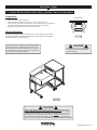
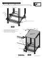
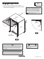
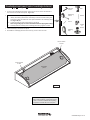
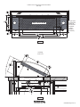
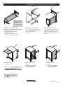
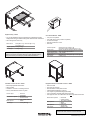
Owner’s Manual
Freedom One eLift Lectern™
55357
Important
Before using this product:
• Read this manual
• Comply with all safety and operating instructions
• Ensure all parts and correct quantities are included
Any parts damaged during shipment must be reported
within 15 days of receipt. To report information regarding missing parts or damage, to purchase parts or
accessories, or if you have any questions, please
contact us.
Thank you for purchasing Spectrum products!
Spectrum Industries, Inc
925 First Avenue, Chippewa Falls, WI 54729 USA
800 235 1262
715 723 6750
www.spectrumfurniture.com
0118408R2 Page 1 of 16
Important Safety and Care Instructions
•
•
•
•
•
•
•
•
•
Read this owner’s manual before assembly or operation.
Do not allow children to move the lectern.
Proceed slowly and carefully when moving the lectern.
For indoor use only. Do not install or store the lectern where it will be exposed
to moisture.
Do not block the ventilation openings.
Avoid uneven loading of the equipment into the lectern. Uneven weight
distribution could cause the lectern to tip when the lectern is moving.
Do not allow anyone to sit, stand, or climb on the lectern.
Use a damp, soft-cloth, or sponge, with mild soap or detergent solution to clean
dirty surfaces. Do not use harsh solvents or abrasives.
This lectern is intended for institutional use. It does not have any userserviceable parts or user-maintenance requirements. If servicing is necessary,
please contact Spectrum Industries for assistance.
Electrical Safety:
• Do not plug the power cord into an extension cord.
• Inspect power cords for damage before each use. Do not use power cords
that are damaged.
• Unplug power cord from electrical outlet by gripping the cord. Do not unplug
the power cord by pulling only on the cord.
• Do not step on, drive over, drag, or place objects on the power cord.
• For added safety, plug the lectern into a grounded outlet controlled by a GFI
(Ground Fault Interrupter) circuit breaker.
• Electrical devices are not toys. Children are often unaware of the hazards
associated with electrical devices. This lectern must always be used by
adults or with adult supervision.
Warning - Relocating audio and/or video equipment to furniture not specifically
designed to support audio and/or video equipment may result in death or
serious injury due to the furnishing collapsing or over turning onto a child.
Warning - Death or serious injury may occur when children climb on audio
and/or video equipment furniture. A remote control or toys placed on the
furnishing may encourage a child to climb on the furnishing and as a result the
furnishing may tip over on to the child.
Hardware
Equipment Rack
(included with select configurations)
(2) 0105965
3” Swivel Stem Casters with brake
(1/2-13 thread)
(4) 055194
Glide (1/2-13 x 1” thread)
(only included with units
configured with glides)
(2) 0105966
3” Swivel Stem Casters
(1/2-13 thread)
Unit-to-Unit Brackets
(included with select configurations)
(2) 0118062
Unit-to-Unit Connectors
(4) 052605
1/4-20 x 15mm
JC bolts
(4) 053310
1/4-20 x 40mm
JC bolts
(1) 025039
4mm Hex wrench
Flip-Up Shelf
(included with select configurations)
(1) 0118086
Flip-up shelf
assembly
(4) 0100167
8-32 x 1/2” PH
Thread-cutting
screw
0118408R2 Page 2 of 16
Assembly / Setup
1. Lectern lift mechanism initial setup, operation, and reset procedure
Preparation:
Control buttons
• Read all instructions before operation.
• Make sure lectern is plugged-in using the 15-foot, 15-amp power cord.
• Locate the “Up” and “Down” control buttons. Control pad is located on the instructorside under the worksurface front edge on opposite side from rack cabinet.
• Keep clear of pinch points during worksurface movement.
Normal Operation:
Up
To raise or lower the lectern, press and hold the “up” or “down” arrow keys on the control
pad until the worksurface reaches the desired height. The worksurface can be adjusted
from 28.5”H (minimum) to 42”H (maximum).
Down
Figure 1A
CAUTION
Note: The lectern has a load-sensing, anti-collision feature
programmed into the controller that actively locks out the
lift mechanisms when unbalanced loads are encountered;
i.e. an obstruction under the worksurface, or weight from a
person sitting on one side of the lectern.
Keep clear of pinch points during worksurface movement. Note: The lift actuators
provide 540 lb of lift.
Figure 1B
CAUTION
Always unplug the lectern before working under the worksurface. Do not place
anything under the worksurface when operating lift. Although this lectern utilizes an
anti-collision feature that briefly stops and reverses the worksurface motion in the event
of an obstruction, use caution when raising or lowering. Do not sit at, under, or on the
worksurface when operating the lift mechanism and be sure lectern movement does not
interfere with objects or people. Use caution when raising or lowering the worksurface!
0118408R2 Page 3 of 16
1.
2.
3.
On a non-abrasive surface, carefully tip the equipment rack onto its back (audience side). Figure 2.
Install the included stem casters or glides and tighten securely.
Note: 2 locking casters should be installed on the instructor-side for easy-access.
Tip the equipment rack back upright.
Tools
Required
2. Attach equipment rack casters / glides
17mm
open end
wrench
Locking stem
caster
tru
s
In
or
ct
si
de
Stem caster
e
nc
ie
ud
A
de
si
Glide
Figure 2
0118408R2 Page 4 of 16
1.
2.
Determine which side of the lectern the equipment rack is to be installed (left or right side). (Right-side installation shown.)
Attach the unit-to-unit brackets to the equipment rack side panel mounting holes with (4) 1/4-20 x 15mm JC bolts. Figure 3A.
Tools
Required
3. Connect lectern and equipment rack
4mm hex
wrench
Equipment Rack
(2) 1/4-20 x
15mm JC bolts
Unit-t
o-Unit
Unit-t
o-Unit
brack
et
brack
et
(2) 1/4-20 x 15mm JC bolts
Figure 3A
3.
4.
Bring the equipment rack to the lectern and align the unit-to-unit
brackets with the mounting holes in the lectern leg.
Install (4) 1/4-20 x 40mm JC bolts through the top of the
lectern leg and tighten securely. Figure 3B.
Lectern
Equipment Rack with
installed unit-to-unit
brackets
(4) 1/4-20 x 40mm
JC bolts
Lectern leg
Figure 3B
0118408R2 Page 5 of 16
1. Determine which side of the equipment rack the shelf is to be installed.
2. Extend and lock the folding shelf brackets into the horizontal position. Figure 4A.
3. Align and attach each bracket to the side of the lectern with (2) 8-32 x 3/8” PHM
screws and tighten securely. Figure 4B.
Tools
Required
Installing flip-up shelf (select units)
Phillips
screwdriver
Note: The flip-up shelf option may not be included with
all configurations. The shelf is designed for use on
Freedom One eLift equipment racks that are attached to
the lectern with unit-to-unit connectors. It is not recommended for use on stand-alone equipment racks.
The shelf is to be installed on the equipment rack side
opposite the Freedom One Lectern.
Folding shelf
brackets
Release lever
(press here)
Folding shelf
bracket
Equipment
Rack
Figure 4A
8-32 x 1/2” PH
thread-cutting screw
(2 required per bracket)
Figure 4B
Operation
The shelf will automatically lock into place when lifted into the horizontal
position with the levers released. Figure 4A. To lower or flip-up the shelf,
press and hold the levers under each folding shelf bracket at the same time
while slowly lowering or raising the shelf. Do not exceed a maximum of
50 lb of weight on the shelf. Do not move the unit while the shelf is in the
horizontal position.
CAUTION
Keep clear of pinch points during shelf
movement. Do not exceed 50 lb [22.68 kg]
of weight on shelf.
Note: Power and communication wiring for document cameras, laptop
computers, and / or projectors placed on the flip-up shelf should be routed
on top of the audience-side of the shelf. Use of the shelf grommet hole for
wiring will result in pinching of the cords when the shelf is folded.
0118408R2 Page 6 of 16
Overbridge insert panel (select overbridge lecterns)
4mm hex
wrench
Drill
1. To remove the overbridge insert panel, remove the (2) 1/4-20 x 35mm JC bolts with a
4mm hex wrench and lift out the panel. Figure 5A.
Tools Required
2. To make cutouts in the insert panel [optional]:
1. Identify all location(s) and sizes for controller(s) or electronics while making sure
all devices fit within the maximum cutout space available in the overbridge panel.
See Figure 5B, 5C.
2. Locate and mark the exact cutout area(s) on the panel.
Note: Using masking tape on cut lines will minimize laminate chipping while cutting.
3. Carefully make the cutout(s) in the overbridge panel using a jigsaw or router.
3. Install controller(s) / electronics into panel.
4. Re-install the overbridge panel and secure with (2) 1/4-20 x 35mm JC bolts.
Measuring
device
Drill bit
Pencil
Jigsaw
or
Router
Masking
tape
1/4-20 x 35mm
JC bolt
1/4-20 x 35mm
JC bolt
Overbridge
panel
Figure 5A
Note: Blank overbridge panels require the customer to make necessary cutouts with a jigsaw
or router. This has a moderate difficulty rating,
so experience and skill with tools is required.
0118408R2 Page 7 of 16
Freedom One eLift Overbridge Insert Panel Blank
(flat view)
2” grommet
2” grommet
Max cutout area
Cutouts should
be avoided here
if device will
descend below
worksurface
(Actuator
plug below
worksurface)
Worksurface opening below
Figure 5B
Overbridge
section view
Worksurface opening below
Figure 5C
0118408R2 Page 8 of 16
Wiring Diagram
Up / Down
buttons
Actuator
Actuator
Wire Loom
To wall outlet
Control Box
Figure 6
Note: The shroud panel can
be removed with 2 screws and
the worksurface extended to
access internal wiring.
0118408R2 Page 9 of 16
Tools
Required
Removing equipment rack audience-side panel
The audience-side panel can be removed to access the rear portion of the equipment rack.
1.
2.
3.
To remove the panel, remove the (2) 1/4-20 x 5/8” PHM screws under the worksurface edge. Figure 7.
Let the panel drop slightly from the 4 installed frame screws, then remove the panel.
To reattach, align the 4 keyhole slots with the installed frame screws, and push the panel up to the worksurface. Make sure the panel fully contacts the vertical equipment rack frames.
Re-install the (2) 1/4-20 x 5/8” PHM screws and tighten securely.
E
q
A u ip
ud m
ie e n
nc t
e - Ra
si c
de k
4.
Phillips
screwdriver
/8”
x5 s
0
2
ew
1/4 scr
M
PH
Pre-installed
frame screws
s
ce-
en
udi
l
ane
p
ide
A
Figure 7
Keyhole slot
X4
Moving and parking the lectern
•
•
•
•
•
•
•
•
•
•
•
•
Before moving, unplug and secure all power cords.
Close and lock doors.
Remove any items from the top of the worksurface.
Unlock the casters.
Push slowly and carefully. Do not move over uneven or irregular surfaces.
Do not allow children to move.
Lock the casters after moving.
Do not park unit in areas of heavy traffic.
Do not run power cords across hallways, classrooms, or other areas where they will be walked on.
Do not leave unit unattended in areas where children have access.
Keep doors closed and locked whenever unit is unattended or parked.
Keep casters locked whenever the lectern is unattended.
0118408R2 Page 10 of 16
Accessories
(Available separately after initial configured purchased)
UR
YO
The 96507 Insert Panel
is available to customers
needing a replacement
panel or different cutouts
for technology upgrades.
Overbridge Insert Panel Blank - 96507
Overbridge Insert Panel with cutouts - 96507mod
• For overbridge version only
• Contact Spectrum to specify cutout
size(s) and location(s)
• Overbridge not available separately
• Includes two 2” grommets with covers
E
ER
OH
G
LO
Unit-to-Unit Connector Kit - 55359
Customized Logo Panel - 55380
• For connecting equipment rack to lectern
• Simple installation-lectern and equipment
rack can remain right-side up
• 9 lb [4.1 kg]
• To get a customized logo panel, contact
Spectrum to specify all logo details
• New logos require a first time logo charge
• 26”W [66 cm] x .625”D [1.6 cm] 19.09”H
[48.5 cm]
Flip-up Shelf - 55378
Clear Acrylic Door - 68153
Solid Door - 68152
• Includes 2” grommet
• Locking
• For instructor-side installation
• Can be installed to be hinged
from the left or right side
• Locking
• For instructor-side installation
• Can be installed to be hinged
from the left or right side
Dimensions:
21.1875”W [53.8 cm] x 30”D
[76.2 cm] x 1”H [2.54 cm]
Weight capacity: 50 lb [22.7 kg]
Unit weight:
N/A
Note: Not recommended for use
on stand-alone equipment racks.
0118408R2 Page 11 of 16
Keyboard Tray - 55379
Cove Power Module - 99044
• Tray can be installed and used as a keyboard tray or flipped and used as a
storage drawer using pre-drilled mounting holes under the lectern worksurface.
• Wire management slots in tray
•
•
•
•
•
Dimensions:
22”W [55.9 cm] x 13.815”D [35.1 cm]
x 4”H [10.2 cm]
Weight capacity: 25 lb [11.4 kg]
Unit weight:
14 lb [5.4 kg]
Two power receptacles
Two USB charge ports (not data-compatible)
Thumbscrew clamps
Requires worksurface cutout
ETL listed
Cutout required:
5.25”W [13.3 cm] x 2”D [5.1 cm]
(mounts to surface thicknesses up to 1.5”)
Power cord:
9’ [274 cm] with 90° flat plug with 45° rotation
Power receptacles: 12A, 120 VAC spill-resistant
USB charging ports: 2.1A (10.5W)
Dimensions:
6”W [15.2 cm] x 2.5”D [6.35 cm] x 3.18”H [8.1 cm]
Unit weight:
2.29 lb [1 kg]
Note: The keyboard tray protrudes 3.4375” [8.73 cm] below the worksurface. If the lectern is used for ADA use, a higher adjusted worksurface (around 32”H) is necessary to provide wheelchair clearance.
Freedom One eLift Lectern - 55357
Equipment Rack for Freedom One eLift - 55358
•
•
•
•
•
•
•
•
•
•
•
Electrically-adjustable worksurface
ADA-compliant
Available in surround or overbridge versions
Factory-assembled with casters or glides
Lectern Style:
Worksurface options:
Base options:
Unit weight:
•
•
•
•
•
•
Surround
Overbridge
No Cutouts
Custom Cutouts
Twin Wheel Casters
Glides
151 lb [68.6 kg]
Rack rail: 18RU
Front and rear rack rails
Standard audience-side panel included
Casters/glides assembled by customer
39.11”H [99.3 cm] worksurface height (with casters)
Two 2” grommets in each side panel provide cord access
One equipment rack can be attached to the left and right sides of the lectern
Worksurface options:
Base options:
Door options:
Unit weight:
•
•
•
•
•
•
No Cutouts
Custom Cutouts
Twin Wheel Casters
Glides
Solid door
Acrylic door
83 lb [37.7 kg]
See spectrumfurniture.com for the latest available flat
panel monitor arms, and rack-mount accessories.
0118408R2 Page 12 of 16
Electric leg information
Warning!
Only for EU markets
Failure to comply with these instructions may result in accidents involving serious personal injury.
Failing to follow these instructions can result in the product being damaged or being destroyed.
Safety Information
General
Safe use of the system is possible only when the operating instructions are read
completely and the instructions contained are strictly observed. Failure to comply with
instructions marked with the ”NOTE” symbol may result in serious damage to the system
or one of its components.
• It is important for everyone who is to connect, install, or use the systems to have the
necessary information and access to the Owners Manual. Follow the instructions for
mounting – risk of injury if these instructions are not followed.
• The appliance is not intended for use by young children or infirm persons without supervision.
• If there is visible damage on the product it must not be installed.
• Note that during construction of applications, in which the actuator is to be fitted, there
must be no possibility of personal injury, for example the squeezing of fingers or arms.
Assure free space for movement of application in both directions
to avoid blockade.
• This appliance can be used by children aged from 8 years and above and persons
with reduced physical, sensory or mental capabilities or lack of experience and
knowledge if they have given supervision or instruction concerning use of the
appliance in a safe way and understand the hazards involved.
• Children shall not play with the appliance. Cleaning and user maintenance shall not
be made by children without supervision.
Only for Non-EU markets
• Persons who do not have the necessary experience or knowledge of the product/
products must not use the product/products. Besides, persons with reduced physical,
sensory or mental abilities must not use the product/products, unless they are under
surveillance or they have been thoroughly instructed in the use of the apparatus by a
person who is responsible for the safety of these persons.
• Moreover, children must be under surveillance to ensure that they do not play with
the product.
• It is the operator’s responsibility to ensure that there is free space for the application to
move without risk for the operator or bystanders before operating the application.
Misuse
• Do not overload the actuators – this can cause danger of personal injury and
damage to the system.
• Do not use the actuator system for lifting persons. Do not sit or stand on a table
while operating – risk of personal injury.
• Do not use the system in environments other than the intended indoor use.
Before installation, re-installation, or troubleshooting:
Repairs
• Stop the DL5/DL6
• Pull out the mains plug.
• Relieve the DL5/DL6 of any loads, which may be released during the work.
In order to avoid the risk of malfunction, all DESKLINE® repairs must only be carried
out by authorised LINAK workshops or repairers, as special tools must be used and
special gaskets must be fitted. Lifting units under warranty must also be returned to
authorised LINAK workshops.
Before start-up:
• Make sure that the system has been installed as instructed in this User Manual.
• Make sure that the voltage of the control box is correct before the system is connected
to the mains.
• System connection. The individual parts must be connected before the control box is
connected to the mains. See the User Manual for LINAK actuators, if necessary.
Warning! If any of the DESKLINE® products are opened, there will be a risk of
subsequent malfunction.
Warning! The DESKLINE® systems do not withstand cutting oil.
During operation
•
•
•
•
If the control box makes unusual noise or smells, switch off the mains voltage immediately.
Take care that the cables are not damaged.
Unplug the mains cable on mobile equipment before it is moved.
The products must only be used in an environment, that corresponds to their IP protection.
Misc.
The actuator system has a sound level below 55dB(A) in typical applications.
Updated manuals and declarations can always be found here:
www.linak.com/deskline
CBD4
DL6
0118408R2 Page 13 of 16
Misc. on the DESKLINE® DL5/DL6 system
Electrical connection of the DL5/DL6 system
This system is a DESKLINE system developed for desks and for indoor use in offices. Do not
use it in industrial kitchens or in other enviroments that have to be cleaned with aggressive
detergents. Do not bolt the legs to the floor so that free movement is prevented. This could
cause serious damage to the legs in fault situations.
The DESKLINE® DL5/DL6 system is to be connected as shown on figure 4. Each DL5/
DL6 is to be connected to the sockets on the control box by means of the motor cables,
which have an 6-pin plug in each end. Finally, the mains cable is to be mounted and
power switched on.
Warranty
There is a 36 months’ warranty on the DESKLINE products against manufacturing faults
from the production date of the individual products (see label).
LINAK A/S’ warranty is only valid in so far as the equipment has been used and maintained correctly and has not been tampered with. Furthermore, the system must not be
exposed to violent treatment. In the event of this,
the warranty will be ineffective/invalid. For further details, please see LINAK A/S ordinary
conditions of sale.
Maintenance
Clean dust and dirt on the outside of the system at appropriate intervals and inspect them
for damage and breaks. Inspect the connections, cables, and plugs and check for correct
functioning as well as fixing points.
Service of double-insulated products:
Please note that the control box must only be connected to the voltage stated on the
label.
CBD4/CBD5/CBD6 with earth
The CBD4/CBD5/CBD6 earth cable to be mounted on the desk construction (typically the top
frame) in a way that ensures good electrical contact. The function of the earth cable is to earth
the desk and ground static electricity. The earth connection does not protect other electrical
products.
CBD4/CBD5 with mains cut-off (non ZERO models)
If the power cable is damaged it has to be replaced by an authorized LINAK
service centre to avoid any danger.
Class II
A Class II or double insulated electrical appliance is one which has been designed in
such a way that it does not require a safety connection to electrical earth (US: ground).
DL5/DL6 cable
hook for cable relief
The basic requirement is that no single failure can result in dangerous voltage becoming
exposed so that it might cause an electric shock and that this is achieved without relying
on an earthed metal casing. This is usually achieved at least in part by having two layers of
insulating material surrounding live parts or by using reinforced insulation.
There is no earthing/grounding means provided on the product, and no earthing/grounding means is to be added to the product.
In Europe, a double insulated appliance must be labelled “Class II”, “double insulated” or
bear the double insulation symbol (a square inside another square).
Servicing a double-insulated product requires extreme care and knowledge of the system,
and is to be done only by qualified service personnel. Replacement parts for a double-insulated product must be identical to the parts they replace.
main
cable
DL5/DL6
DP/WDPL
DL5/DL6
The cleaners and disinfectants must not be highly alkaline or
acidic (pH value 6-8).
Anti-Collision™
Description of the DESKLINE® DL5/DL6 system
Each DESKLINE® DL5/DL6 lifting units is equipped with a motor and parallel/memory
drive is ensured by means of software in the CBD4/CBD5/CBD6 that also takes account
of oblique load on the desk. Soft start and stop are also part of this software, which
ensures a soft start and stop when adjusting the desk.
Application of the DESKLINE® DL5/DL6 system:
Irrespective of the load the duty cycle 10% ~ 6 min./ hour or max. 2 min. at
continuous use stated in the data sheets, must NOT be exceeded as this will result
in a superheating of the motor, the brake and the spindle nut. Exceeding the duty cycle
will result in a dramatic reduction of the life of the system.
The DESKLINE® DL5/DL6 system range contains the following products:
• 1 control box CBD4/CBD5/CBD6
• 1 single DL5/DL6 or 2, 3, or 4 parallel
• 1 exchangeable mains cable
• 1, 2, 3, or 4 motor cables
• 1 DP1U/DPF1M (if memory function is required) DP1C/WDPL/DPT/DPF1C (if
memory function and display is required) or 1 DPA/DPB/DP1K/DP1V/DPF1K (if only
up/down is required.)
The function (anti-collision) is an option for the standard CBD4/CBD5/CBD6 advanced/
control box software 0077432 version 1.66 and later. A system with anti-collision can limit
material damages on a desk if a collision with a solid object should occur
Method of operation
When the DL/DB’s are running the CBD4/CBD5/CBD6 monitors the current
consumption on each channel using a special algorithm. If the current consumption
on one channel is increased more than a predefined slope, a collision is assumed and
all channels are stopped immediately and all DL/DB’s will start to run in the opposite
direction (approx. 50 mm). This return drive is done automatically and continues with
or without any control key pressed (for max. 2.5 sec.).
The anti-collision sensitivity is different in upward and downward direction. Upwards
the force is approx. 20 kg. Downwards the load will be approx. 40 kg + the load on the
DL/DB (the desk + what is on top of the desk). The 40 kg are needed to activate the
anti-collision function.
Situations where the anti-collision does not work
There are situations where the anti-collision will not be activated. These situations are:
• If the collision happens during the initialisation phase
• If the collision happens within the first 1000 msec or after the control button has
been released
• If the collision happens between the floor and the table and the load on the desk +
the weight of the legs are lower than 40 kg
• If the collision happens over too long time, e.g. if the collision is with a soft object.
0118408R2 Page 14 of 16
Freedom One eLift Lectern Troubleshooting Guide
Symptom
Problem
Solution
Loss of power
Be sure control box is plugged into a live circuit.
Loose electrical connections
Make sure all electrical connections are securely plugged into the control box.
See wiring diagram on p.9 for reference.
Object encountered under
the lectern worksurface
1. Raise the worksurface by pressing the “up” button.
2. Remove any items under the lectern worksurface.
3. Reset the lift mechanism (see below for procedure.)
Solution #1
1. Unplug, then re-plug the power cord into a wall outlet.
2. Make sure all lift mechanism wire connections are in place and secure.
3. Remove anything located under the lectern worksurface.
Worksurface will
not operate
4. Press and hold the “Down” button to lower the worksurface to the lowest position
until it stops moving.
Misaligned actuators due to
unbalanced loads
5. Release the “Down” button.
Note: If the worksurface does not lower when doing this step, release the
“Down” button, and retry steps 1-5.
6. Release the “Down” button. The lift mechanism has now been reset and the
worksurface can be adjusted normally.
Solution #2
1. Detach one of the actuators from the worksurface.
2. Lower the lectern all the way down.
3. Re-attach the actuator to the worksurface.
WARNING
Be sure the lectern movement does not interfere with objects or
people. Do not place any items under the lectern worksurface.
Note: For mobile use only-not designed
to be permanently anchored to floors
0118408R2 Page 15 of 16
Warranty
WE WILL MAKE IT RIGHT FOR YOU!
Spectrum is committed to provide complete customer satisfaction. Each of our products is manufactured from the best materials available and each
product is stringently monitored throughout the production process through our P.A.C.E. program (Product Assurance to meet Customer Expectations).
We expressly warrant that Spectrum products will be of good quality and workmanship and free from defect for the period set out in the warranty table below
from the date of delivery. This warranty shall not apply to defects or damage resulting from misuse, abuse, neglect, improper care, modification or repair not
authorized by Spectrum, or any other cause outside the control of Spectrum. Spectrum will, at its sole option, either repair or replace the defective product.
This warranty is exclusive; no other warranty, written or oral, is expressed or implied. This warranty is given by Spectrum to Buyer and to no other person or legal entity. No Spectrum dealer, distributor, agent or employee is authorized to make any modification or addition to this warranty.
NOTWITHSTANDING ANYTHING TO THE CONTRARY, SPECTRUM WILL NOT UNDER ANY CIRCUMSTANCES BE LIABLE FOR INDIRECT OR LIQUIDATED DAMAGES, INCLUDING CONSEQUENTIAL, INCIDENTAL AND SPECIAL DAMAGES. IN NO EVENT SHALL SPECTRUM’S LIABILITY, WHETHER
UNDER CONTRACT OR WARRANTY, IN TORT OR OTHERWISE, EXCEED THE PURCHASE PRICE RECEIVED BY SPECTRUM FOR THE PRODUCT AT
ISSUE AND “RECALL ACTION” EXPENSES. SPECTRUM SHALL NOT BE SUBJECT TO ANY OTHER OBLIGATIONS OR LIABILITIES, WHETHER ARISING OUT OF BREACH OF CONTRACT, WARRANTY, TORT (INCLUDING NEGLIGENCE AND STRICT LIABILITY) OR OTHER THEORIES OF LAW, WITH
RESPECT TO PRODUCTS SOLD OR SERVICES RENDERED BY SPECTRUM, OR ANY UNDERTAKINGS, ACTS OR OMISSIONS RELATING THERETO.
Our Customer Service Department is ready to provide immediate attention to any questions, comments or concerns. They are available to answer your calls
Monday through Friday from 7 am to 5 pm CST. In addition your product comments or concerns are welcome via e-mail at: [email protected].
Warranty Table
Item
Adjustable Crank / Electric Desk Legs
Flat Panel Desk Gas Cylinders
Chairs
• Adjustable Height Chair Parts – including frames, gas
cylinders, wood and plastic parts, control handles, casters
• Adjustable Height Chair Upholstery
• In-Stock Upholstery
• Graded-In Fabrics and Customer Owned Material
Height Adjustable Columns and Lifts
General Use Casters
effective 1/1/2015
Warranty Period
• 1 Year
• 7 Years
• 2 Years
• 2 Years
• No Warranty
• 1 Year
Electrical (including timers and LINAK actuators)
• 2 Years
Keyboard / Mouse Trays
• 1 Year
Flat Panel Monitor Arms
• Flat Panel Monitor Arm – General Parts
• Flat Panel Monitor Arm – Gas Cylinders
• 5 Years
• 2 Years
Desks and Lecterns
• Computer Desk Chassis
• Cart Chassis
• Lectern Chassis
• 10 Years
8
925 FIRST AVENUE, CHIPPEWA FALLS, WI 54729 / 800-235-1262 / 715-723-6750 / WWW.SPECTRUMFURNITURE.COM
0118408R2 Page 16 of 16


![取扱説明書[PDF:3.6MB]](http://vs1.manualzilla.com/store/data/006628547_3-e54ea06345f6aab36157749c619a5a32-150x150.png)