1
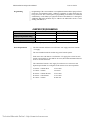
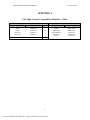
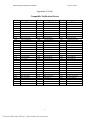
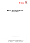
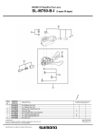
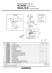
ZNS
MICROPROCESSOR BASED
CONVENTIONAL FIRE ALARM CONTROL
PANEL
Installation & Operation Manual
The Gamewell Company
60 Pleasant Street
Ashland, MA 01721
Part No. 71774
Issue 4 12/4/98
PROPRIETARY MATERIAL
Technical Manuals Online! - http://www.tech-man.com
ZNS Installation and Operation Manual
Issue 4 12/4/98
The information contained in this manual is proprietary to The Gamewell Company. Such
information and technical drawings may not be copied or reproduced in any manner, or disclosed to
organizations that might be competitive to Gamewell, without the express prior written consent of
The Gamewell Company.
Technical Manuals Online! - http://www.tech-man.com
ZNS Installation and Operation Manual
Issue 4 12/4/98
GENERAL INFORMATION
The Gamewell Company thanks you for choosing the ZNS Microprocessor based fire alarm control panel.
As with all our products we have taken great care to insure that we have provided a quality product. To
receive maximum benefit and many years of reliable service we would like to make the following
recommendations:
1.
Read this manual carefully and in it's entirety before proceeding with the installation of the
ZNS panel.
2.
Never make any connections with the power connected.
3.
Gamewell spends many hours testing devices that are supplied by Gamewell to be used with
it's control panels to verify compatibility. To maximize system performance, and minimize
risk of damage to the equipment, we suggest using all Gamewell Components.
4.
There is no substitute for proper maintenance and testing of this or any life safety
product. Gamewell recommends testing and maintenance of your ZNS in accordance with the
guidelines set forth by the National Fire Protection Association, to be done on a regular basis,
as a minimum.
5.
This manual should be stored with the ZNS panel for future reference, and should not be
removed, providing reference to the operation and programming of the installed ZNS
Thank you again for choosing Gamewell. If you have any comments regarding your ZNS panel or other
Gamewell products, please feel free to contact us at:
The Gamewell Company
Product Marketing Department
60 Pleasant Street
Ashland, MA 01721
Technical Manuals Online! - http://www.tech-man.com
ZNS Installation and Operation Manual
Issue 4 12/4/98
TABLE OF CONTENTS
Overview
Description
1
1
INSTALLATION AND WIRING
Mechanical
Wiring
1
1
1
Common Card
Indicators
Default Operation
Auxiliary Power
Programming
2
2
2
2
2
Zone Card
Indicators
Alarm Disconnect
Low /High Current Operation
Addressing
Zone Programming
Programming
Power Requirements
2
2
2
2
2
2
3
3
Appendix A
ZNS High Current Compatibility Identifier - 31016
Compatible Notification Devices
4
4
5
Appendix B
Drawings
6
6
Technical Manuals Online! - http://www.tech-man.com
ZNS Installation and Operation Manual
Issue 4 12/4/98
GAMEWELL ZNS
This manual covers the installation, programming and service of the ZNS and its related modules. It
is a supplement to the INS-2 Installation and Programming manuals (P/N’s 70708-05 and 70709-04).
OVERVIEW
Description
The ZNS is a microprocessor based conventional Fire Alarm Control Panel. It is
designed to monitor 2 to 32 conventional initiation zones and also allows 2 circuits of
addressable detection or control devices. The main control panel consists of an
addressable INS-2 system. Addition of an ZNS Common Module provides
connection to the conventional zone modules.
INSTALLATION AND WIRING
Mechanical
Two cabinet sizes are available for the ZNS the smaller is used to house a 2 to 16
zone system and the larger is used on 2 to 32 zone systems.
21”W x 25.5”H x 4”D (1 to 16 zones)
21”W x 31.5”H x 4”D (2 to 32 zones)
The ZNS Common Module (p/n 31014) mounts in place of the INS-2 expander
module and plugs into the J5 connector. It is connected to the p/n 31015 Zone Mother
Board modules. Each mother board accepts two p/n 31016 two zone Conventional
Input Module. Refer to drawings A-M1104, D-M780 and D-M781 for mechanical
layout.
Wiring
Both high or low current zone should be wired in accordance with NFPA 70, article
760. Maximum loop resistance should not excede 25 ohms. Refer to wiring diagram
A-W544 for terminations.
1
Technical Manuals Online! - http://www.tech-man.com
ZNS Installation and Operation Manual
Issue 4 12/4/98
COMMON CARD
Indicators
The ZNS common card module has one LED. When first powered it flashes the
version number of the firmware on the ZNS module. Thereafter it will flash
whenever it is responding with zone information to an INS-2 poll.
Default Operation
Default operation is a mode that allows alarms to be sensed and automatically routed
to the Signaling Circuits, if for some reason the ZNS controller fails.
Auxiliary Power
Auxiliary power is available on the Common Card from terminals A+, A-. Resetable
smoke detector power is available from terminals S+, S-. This power is removed for
four seconds when the system is reset. Combined total current available from both
A+,A- and S+,S- is 0.5 amps.
Programming
The ZNS Common Card is enabled by accessing level 4 programming area of the
INS-2 main board. Press the F1 key until the LED above the F1 key is illuminated.
Output controller location C220 must also be enabled and cannot be used by any
other devices. This output controller location allows the ZNS common card to reset
the S+, S- output.
ZONE CARD
Indicators
Each 2 zone module has two LED’s per zone, one to indicate alarm and the other to
indicate trouble. The standard zone module has a red and yellow, the supervisory
zone has two yellow LED’s.
Alarm Disconnect
Each zone of the 31016 2 zone card has a disconnect switch located next to the
LEDs. When this switch is activated, the zone will not report an Alarm, but it will
show that it is in Trouble
Each zone of the 31016 2 zone card can be programmed for two modes of operation,
low current and high current. The module is factory set as a high current zone. Low
current mode is selected by removing the following resistors.
Low /High Current
Operation
Resistors to remove for low current operation.
Odd Zone
R1,R2,R3
Even Zone
R21,R22,R23
The EOL resistor high current value is 4.7K ohms and the low current value is 15K
ohms.
NOTE: Low Current zones will not function with 2-wire Smoke Detectors, and
should be used with contact closure devices only.
Addressing
The 31016 zone modules must be mounted from left to right. If a slot is empty the
system will not detect modules beyond the first open slot.
Zone Programming
Each 31016 2 zone card has jumpers to distinguish between Class A or Class B
initiating circuits. There are also jumpers to program latching and non-latching
zones. All 31016 modules are factory set for Class B latching alarm operation. See
the chart below for programming options. Refer to drawing A-M1105 For resistor
locations.
2
Technical Manuals Online! - http://www.tech-man.com
ZNS Installation and Operation Manual
Programming
Issue 4 12/4/98
Programming of the 31016 modules is accomplished with the INS-2 laptop software.
Each zone card installed requires 2 addresses regardless of wether both zones are
being used or not. The 31016 requires no programming of its address. It is addressed
automatically, via the ZNS, by its physical location to the addresses of 1 through 32.
Additional addressable modules may be added to the addressable circuits 1 and 2
starting with address 33.
JUMPER PROGRAMMING
Odd Zone
Even Zone
Alarms Latched
W1L Installed
W2L Installed
Alarms Not Latched
W1L Removed
W2L Removed
(Supervisory Alarms Only)
Class B
W1A Installed
W2A Installed
Class A
W1A Removed
W2A Removed
Zone cards are shipped with all jumpers installed (Class B, Alarms Latched).
Power Requirements
The ZNS common card draws 2 mA from the +24V supply and 5 mA from the
+5V supply.
The 31015 mother boards do not draw any power from the system.
Each 31016 zone card draws 0.5 mA from the +5V supply plus 6.5 mA for each
trouble or alarm LED on. Note that for one zone, the trouble and alarm LEDs will
never be on at the same time.
The current draw from the +24V supply for each zone on a 31016 zone card
depends upon whether it is configured for hi-current or low current operation.
lo-current -- without detect
lo-current -- in alarm
2.5 mA max
6 mA max
hi-current -- without detectors
hi-current -- with detectors
hi-current -- in alarm
6.5 mA max
9.1 mA max
60 mA max
3
Technical Manuals Online! - http://www.tech-man.com
ZNS Installation and Operation Manual
Issue 4 12/4/98
APPENDIX A
ZNS High Current Compatibility Identifier - 31016
Gamewell Model No.
71033
71034
71035
71035-160
71035-210
71443
Detectors
Apollo Part No.
55000-350
55000-250
55000-150
55000-151
55000-152
55000-380
Qty.
20
10
4
Technical Manuals Online! - http://www.tech-man.com
Bases
Gamewell Model No.
Apollo Part No.
71036
45681-200
71086
45681-220
71086-LOW
45681-232
71086-GREEN
45681-231
71086-RED
45681-230
71393
45681-227
ZNS Installation and Operation Manual
Issue 4 12/4/98
Appendix A (Cont)
Compatible Notification Devices
Part #
Catalog #
Part #
Catalog #
Part #
Catalog #
70871
70873
71138
71140
71287
71288
71289
71290
71292
71293
71294
71295
71426
71427
71543
71544
71545
71546
71547
71548
71549
71550
71551
71552
71553
71554
71555
71556
71557
71558
71559
71560
71561
MIZ-24-R
MIZ-24-W
MT-12/24-R
MT-24-WM-VFR
MIZ-24-LS-VFR
MIZ-24-LSM-VFR
MIZ-24-MS-VFR
MIZ-24-IS-VFR
MT-24 -LS-VFR
MT-24-LSM-VFR
MT-24-MS-VFR
MT-24-IS-VFR
MT-24 -SL-VFR
MT-24-SLM-VFR
AS-2415-VFR
AS-241575-VFR
AS-2430-VFR
AS-2475-VFR
AS-24110-HFR
SM-12/24-R
DSM-12/24-R
RS-2415-VFR
SR-2415-VFR
SRP-2415-VFR
RS-241575-VFR
SRP-241575-VFR
SR-241575-VFR
RS-2430-VFR
RSP-2430-VFR
RSP-2475-VFR
RS-2475-VFR
RS-24110-HFR
SRP-24110-HFR
71562
71569
71573
71574
71575
71576
71614
71616
71679
71680
71681
71682
71683
71684
71685
71686
71687
71688
71689
71690
71691
71692
71693
71694
71695
71696
71697
71698
71699
71711
71712
71713
71714
SR-24110-HFR
RSP-241575-VFR
AMT-12/24-R
AMT-24-LS-VFR
AMT-24-IS-VFR
AMT-24-LSM-VFR
MT4-12/24-R
SR-2475-VFR
AS-2415W-FR
AS-241575W-FR
AS-2430W-FR
AS-2475W-FR
AS-24110W-FR
AS-24100C-FW
NH-12/24-R
NS-2415W-FR
NS-241575W-FR
NS-2430W-FR
NS-2475W-FR
NS-24110W-FR
RSS-2415W-FR
RSS-241575W-FR
RSSP-241575W-FR
RSSP-2430W-FR
RSS-2430W-FR
RSSP-2475W-FR
RSS-2475W-FR
RSS-24110W-FR
RSS-24100C-FW
AH-24WP-R
RS-2415W-FR
RS-241575W-FR
W3MT-24-VFR
71717
71727
71728
71729
71730
71731
71732
71733
71736
71737
71738
71739
71740
71741
71742
71743
71744
71745
71746
71747
71748
71749
71750
71751
71752
71758
71759
71760
71761
71762
71763
71764
RSSP-24110W-FR
AS-2415C-FW
AS-2430C-FW
AS-2475C-FW
RSS-2415C-FW
RSS-2430C-FW
RSS-2475C-FW
RSSP-2415W-FR
ET70-2415W-FR
ET70-241575W-FR
ET70-2430W-FR
ET70-2475W-FR
ET90-2415C-FW
ET90-2430C-FW
ET90-2475C-FW
ET90-24100C-FW
E70-2415W-FR
E70-241575W-FR
E70-2430W-FR
E70-2475W-FR
E70-24110W-FR
E90-2415C-FW
E90-2430C-FW
E90-2475C-FW
E90-24100C-FW
CH90-24-W
CH70-24-R
CH70-2415W-FR
CH70-241575W-FR
CH70-2430W-FR
CH70-2475W-FR
CH70-24110W-FR
5
Technical Manuals Online! - http://www.tech-man.com
ZNS Installation and Operation Manual
Issue 4 12/4/98
APPENDIX B
Drawings
D-M781
Ass’y of ZNS 16 Zones
D-M780
Ass’y of ZNS 32 Zones
A-M1104
Mounting Instruction: Card Guide
A-M1105
Configuring of 2 - Zone Card
D-W1171
Wiring ZNS System
A-W544
Wiring ZNS 2 Zone Card
6
Technical Manuals Online! - http://www.tech-man.com