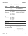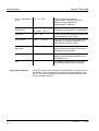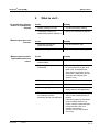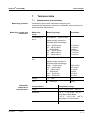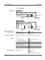
1
Operating manual IQ SENSOR NET TetraCon® 700 IQ (SW) TetraCon 700 IQ TetraCon 700 IQ SW IQ SENSOR NET conductivity sensor ba76018e01 01/2012 TetraCon® 700 IQ (SW) Note For the most recent version of the manual, please visit www.ysi.com. Contact Copyright 2 YSI 1725 Brannum Lane Yellow Springs, OH 45387 USA Tel: +1 937-767-7241 800-765-4974 Email: [email protected] Internet: www.ysi.com © 2012 Xylem Inc. ba76018e01 01/2012 TetraCon® 700 IQ (SW) Contents TetraCon® 700 IQ (SW) - Contents 1 Overview . . . . . . . . . . . . . . . . . . . . . . . . . . . . . . . . . . . . 1-1 1.1 1.2 1.3 2 Safety . . . . . . . . . . . . . . . . . . . . . . . . . . . . . . . . . . . . . . 2-1 2.1 2.2 3 3.4 General maintenance instructions . . . . . . . . . . . . . . . . . 5-1 Cleaning . . . . . . . . . . . . . . . . . . . . . . . . . . . . . . . . . . . . . 5-1 Disposal . . . . . . . . . . . . . . . . . . . . . . . . . . . . . . . . . . . . . 5-2 6 What to do if... . . . . . . . . . . . . . . . . . . . . . . . . . . . . . . . 6-1 7 Technical data . . . . . . . . . . . . . . . . . . . . . . . . . . . . . . . 7-1 7.1 7.2 7.3 7.4 7.5 01/2012 Measuring . . . . . . . . . . . . . . . . . . . . . . . . . . . . . . . . . . . 4-1 Application-dependent settings . . . . . . . . . . . . . . . . . . . 4-2 4.2.1 General information . . . . . . . . . . . . . . . . . . . . . . 4-2 4.2.2 Determining the cell constant in a user-specific measuring environment . . . . . . . . . . . . . . . . . . . 4-3 Maintenance, cleaning, disposal . . . . . . . . . . . . . . . . 5-1 5.1 5.2 5.3 ba76018e01 Scope of delivery . . . . . . . . . . . . . . . . . . . . . . . . . . . . . . 3-1 Installation . . . . . . . . . . . . . . . . . . . . . . . . . . . . . . . . . . . 3-1 Commissioning / Getting the instrument ready for measuring . . . . . . . . . . . . . . . . . . . . . . . . . . . . . . . . . 3-2 ® TetraCon 700 IQ (SW) setting table . . . . . . . . . . . . . . . 3-3 Measuring / Operation . . . . . . . . . . . . . . . . . . . . . . . . . 4-1 4.1 4.2 5 Authorized use . . . . . . . . . . . . . . . . . . . . . . . . . . . . . . . . 2-2 General safety instructions . . . . . . . . . . . . . . . . . . . . . . . 2-2 Commissioning . . . . . . . . . . . . . . . . . . . . . . . . . . . . . . 3-1 3.1 3.2 3.3 4 How to use this component operating manual . . . . . . . . 1-1 Structure of the TetraCon® 700 IQ (SW) . . . . . . . . . . . . 1-2 Recommended fields of application . . . . . . . . . . . . . . . . 1-2 Measurement characteristics . . . . . . . . . . . . . . . . . . . . . 7-1 Application characteristics . . . . . . . . . . . . . . . . . . . . . . . 7-2 General data . . . . . . . . . . . . . . . . . . . . . . . . . . . . . . . . . 7-3 Electrical data . . . . . . . . . . . . . . . . . . . . . . . . . . . . . . . . . 7-4 Characteristic data on delivery . . . . . . . . . . . . . . . . . . . . 7-4 0-1 TetraCon® 700 IQ (SW) Contents 8 Contact Information . . . . . . . . . . . . . . . . . . . . . . . . . . . 8-1 8.1 8.2 9 Indexes . . . . . . . . . . . . . . . . . . . . . . . . . . . . . . . . . . . . . 9-1 9.1 9.2 0-2 Ordering & Technical Support . . . . . . . . . . . . . . . . . . . .8-1 Service Information . . . . . . . . . . . . . . . . . . . . . . . . . . . . .8-1 Explanation of the messages . . . . . . . . . . . . . . . . . . . . .9-1 9.1.1 Error messages . . . . . . . . . . . . . . . . . . . . . . . . .9-1 Status info . . . . . . . . . . . . . . . . . . . . . . . . . . . . . . . . . . . .9-1 ba76018e01 01/2012 TetraCon® 700 IQ (SW) Overview 1 Overview 1.1 How to use this component operating manual Structure of the IQ SENSOR NET operating manual IQ Sensor Net Operating Manual System Operating Manual (Ring Binder) IQ Sensor Operating Manual MIQ Module Operating Manual MIQ Terminal Operating Manual Component Operating Manuals Fig. 1-1 Structure of the IQ SENSOR NET operating manual The IQ SENSOR NET operating manual has a modular structure like the IQ SENSOR NET system itself. It consists of a system operating manual and the operating manuals of all the components used. Please file this component operating manual in the ring binder of the system operating manual. ba76018e01 01/2012 1-1 TetraCon® 700 IQ (SW) Overview 1.2 Structure of the TetraCon® 700 IQ (SW) 1 5 2 4 3 5 Fig. 1-2 Characteristics ® Structure of the conductivity sensor (example: TetraCon 700 IQ) 1 Shaft 2 Plug head connector 3 Voltage electrodes 4 Temperature sensor 5 Current electrodes (ring) The principle of the measurement method makes it possible to avoid influences from primary or secondary polarization effects, which ensures a high degree of measuring accuracy. A modern epoxy sealing technique reduces the chances of breakage of the sensor in the rough industrial environment. 1.3 TetraCon 700 IQ TetraCon 700 IQ SW 1-2 Recommended fields of application Stationary measurements in water/wastewater applications. Stationary measurements in seawater and brackish water, aquaculture. ba76018e01 01/2012 TetraCon® 700 IQ (SW) Safety 2 Safety This component operating manual contains special instructions that must be followed during the operation of the TetraCon® 700 IQ (SW) conductivity sensor. Thus, it is essential to read this component operating manual before carrying out any work using this sensor. In addition to this manual, the SAFETY chapter of the IQ SENSOR NET system operating manual must be followed. Always keep this component operating manual together with the system operating manual and any other component operating manuals in the vicinity of the IQ SENSOR NET system. Special user qualifications The sensor was developed for applications in online measuring technology - essentially in the field of wastewater treatment. Thus, we assume that the operators are familiar with the necessary precautions to take when dealing with chemicals as a result of their professional training and experience. General safety instructions Safety instructions in this operating manual can be recognized by the warning symbol (triangle) in the left column. The signal word (e. g. "Caution") indicates the level of the danger: Warning indicates instructions that must be followed precisely in order to prevent serious dangers to persons. Caution indicates instructions that must be followed precisely in order to avoid slight injuries or damage to the instrument or the environment. Other labels Note indicates notes that draw your attention to special features. Note indicates cross-references to other documents, e.g. operating manuals. ba76018e01 01/2012 2-1 TetraCon® 700 IQ (SW) Safety 2.1 Authorized use The authorized use of the TetraCon® 700 IQ (SW) comprises its use as a conductivity sensor in the IQ SENSOR NET. The technical specifications according to chapter 7 TECHNICAL DATA must be observed. Only operation according to the instructions in this operating manual is authorized. Any other use is considered to be unauthorized. Unauthorized use invalidates any claims with regard to the guarantee. Caution Only connect and operate the sensor together with IQ SENSOR NET accessories. 2.2 General safety instructions The sensor left the factory in a safe and secure technical condition. Function and operational safety The failure-free function and operational safety of the sensor is only guaranteed if the generally applicable safety measures and the special safety instructions in this operating manual are followed during its use. The failure-free function and operational safety of the sensor is only guaranteed under the environmental conditions that are specified in chapter 7 TECHNICAL DATA. The specified temperature range (chapter 7 TECHNICAL DATA) must be maintained during the application and transport of the sensor. Protect the sensor, particularly against frost or overheating. Caution The sensor may only be opened by specialists authorized by YSI. 2-2 ba76018e01 01/2012 TetraCon® 700 IQ (SW) Safe operation Safety If safe operation is no longer possible, the sensor must be taken out of operation and secured against inadvertent operation. Safe operation is no longer possible if the sensor: has been damaged in transport has been stored under adverse conditions for a lengthy period of time is visibly damaged no longer operates as described in this manual. If you are in any doubt, contact the supplier of your sensor. Obligations of the operator The operator of the sensor must ensure that the following rules and regulations are followed when dealing with hazardous substances: EEC directives for protective labor legislation National protective labor legislation Safety regulations Safety data sheets of the chemical manufacturer. ba76018e01 01/2012 2-3 Safety 2-4 TetraCon® 700 IQ (SW) ba76018e01 01/2012 TetraCon® 700 IQ (SW) Commissioning 3 Commissioning 3.1 Scope of delivery TetraCon® 700 IQ (SW) The sensor is fitted with protective caps Operating manual. 3.2 Connection cable Installation A sensor connection cable of the SACIQ or SACIQ SW type is required to connect the sensor. The cable is available in different lengths. Compared to the standard model SACIQ, the SACIQ SW sensor connection cable is optimized regarding its corrosion resistance in seawater and brackish water and adapted for use in conjunction with the TetraCon® 700 IQ SW. Information on this and other IQ SENSOR NET accessories is given in the YSI catalog and on the Internet. Note How to connect the SACIQ (SW) sensor connection cable to the terminal strip of an MIQ module is described in chapter 3 INSTALLATION of the IQ SENSOR NET system operating manual. Are the plug connections dry? Before connecting the sensor and sensor connection cable, please make sure that the plug connections are dry. If moisture gets into the plug connections, first dry the plug connections (dab them dry or blow them dry using compressed air). Note Do not suspend the sensor on the sensor connection cable. Use a sensor holder or armature. Information on this and other IQ SENSOR NET accessories is given in the YSI catalog and on the Internet. ba76018e01 01/2012 3-1 TetraCon® 700 IQ (SW) Commissioning Connecting the sensor to the sensor connection cable 1 Take the protective caps off the plug connections of the sensor and the SACIQ (SW) sensor connection cable and keep them safe. 2 Plug the jack of the SACIQ (SW) sensor connection cable onto the plug head connector of the sensor. At the same time, rotate the socket so that the pin in the plug head connector (1) clicks into one of the two holes in the jack. 3 Then, screw the coupling ring (2) of the sensor connection cable onto the sensor up to the stop. SACIQ 2 1 Fig. 3-1 3.3 3-2 Connecting the sensor Commissioning / Getting the instrument ready for measuring 1 Pull the protective cap off the sensor. 2 If required, assign a user-defined name to the sensor (see relevant IQ SENSOR NET system operating manual). 3 Set the sensor (see section 3.4). ba76018e01 01/2012 TetraCon® 700 IQ (SW) Commissioning 3.4 TetraCon® 700 IQ (SW) setting table Menu item Selection/values Explanations Measuring mode Conductivity /cm Measured parameter in the measured value display (TDS = total dissolved solids) Salinity TDS Conductivity /m Measuring ranges with Measuring mode, Conductivity /cm AutoRange 0 .. 20.00 mS/cm 0 .. 200.0 mS/cm These measuring ranges are available for selection. If the AutoRange menu item is selected, the measurement range selection and switchover is made automatically. 0 .. 2000 mS/cm 0 .. 20.00 mS/cm 0 .. 200.0 mS/cm 0 .. 500.0 mS/cm Measuring ranges with Measuring mode, Conductivity /m AutoRange 0 .. 2.000 mS/m 0 .. 20.00 mS/m 0 .. 200.0 mS/m 0 .. 2000 mS/m 0 .. 20.00 S/m 0 .. 50.00 S/m Measuring range in Measuring mode Salinity 0 .. 70 The measuring range is permanently set. Measuring range in Measuring mode TDS 0 .. 2000 mg/l The measuring range is permanently set. Temperature mode °C Unit of the measured temperature value (Celsius, Fahrenheit). °F Temp. compensation none ba76018e01 01/2012 nonlinear For natural waters (groundwater, surface water, drinking water), salinity (seawater) according to IOT linear with setting Other aqueous measuring solutions 3-3 TetraCon® 700 IQ (SW) Commissioning Temp. compensation 0.5 ... 3.0 %/K linear Reference temperature Tref20 (20 °C) Tref25 (25 °C) TDS factor 0,40 .. 1,00 Factor for automatic calculation of the total dissolved solids by the sensor. Cell constant 0.826 ... 1.008 cm-1 Here you can set the cell constant if this is necessary for a special application, e.g. when using a flow-thru vessel. Temperature adjustment -1.5 ... +1.5 K Here you can balance the temperature sensor in the sensor against a reference temperature measurement. The reference temperature is the basis for calculating the temperature compensation. Save and quit The system confirms the saving of the settings and the display switches to the next higher level. Quit The display switches to the next higher level without saving the new settings. Carrying out settings 3-4 Factor for linear temperature compensation. This menu item only appears if linear temperature compensation is selected. Using s, switch from the measured value display to the main menu of the settings. Then navigate to the setting menu (setting table) of the sensor. The exact procedure is given in the relevant IQ SENSOR NET system operating manual. ba76018e01 01/2012 TetraCon® 700 IQ (SW) Measuring / Operation 4 Measuring / Operation 4.1 Measuring Warning Contact with the sample can lead to danger to the user! Depending on the type of sample, suitable protective measures must be taken (protective clothing, protective goggles, etc.). Note Please make sure that the sensor is surrounded by a gap of at least 5 cm at the base and sides (boundary fields) when measuring at the electrodes. If the gap is less than that, the cell constant changes. This leads to incorrect measurement results. If the gap cannot be maintained, e.g. in narrow pipes, the cell constant can be adjusted to suit the installation conditions (see section 4.2.2). Fig. 4-1 ba76018e01 01/2012 Distance of the sensor from the edge 1 Immerse the sensor in the measuring medium. 2 The measured value is immediately available. 4-1 TetraCon® 700 IQ (SW) Measuring / Operation 4.2 Application-dependent settings 4.2.1 General information The TetraCon® 700 IQ (SW) conductivity sensor is stable over the long term. When being used for the authorized use of the sensor in water/ wastewater applications, it is immediately ready for use. Note Normally, the conductivity measuring cell does not age. Special measuring mediums (e.g. strong acids and bases, organic solvents) or temperatures that are too high may considerably reduce its lifetime or lead to damage. No warranty claims can be made for mechanical damage or any failure caused by these types of measuring mediums. Adapting the cell constant to the installation location In the case of special installation conditions, it may be necessary to adapt the cell constant (due to the influence of the measuring environment, e.g. of boundary fields). Note The cell constant is stored in the controller. It is automatically allocated to the substitute sensor when the sensor is exchanged. Cell constants with YSI installation accessories In chapter 7 TECHNICAL DATA of this operating manual you will find the correct values to set for some products of the YSI accessory program that require a correction of the cell constant (if it is possible to give fixed values at all). If necessary, special installation recommendations for the TetraCon® 700 IQ (SW) can be found in the accessory operating manual. In case of doubt it is necessary to determine the cell constant according to section 4.2.2. Note The setting of the cell constant is made in the setting menu of the sensor according to section 3.4. 4-2 ba76018e01 01/2012 TetraCon® 700 IQ (SW) Measuring / Operation 4.2.2 Determining the cell constant in a user-specific measuring environment 1 Immerse the operable conductivity sensor in the test sample in the measuring environment and wait until the measured value is stable. 2 Read the conductivity on the display and note it down (-> χD). 3 Take a representative sample simultaneously with the conductivity measurement and from the immediate vicinity of the sensor if possible. 4 Determine the conductivity of the sample without the influence of boundary fields (-> χX). The measurement can, for example, be performed as follows: Measuring in the laboratory using a laboratory conductivity measuring cell Measuring using the TetraCon® 700 IQ (SW) while observing the bottom and lateral gaps according to section 4.1 MEASURING. Attention: Set the same procedure for the temperature compensation as for measuring the χD! 5 Read and note down the currently set cell constant in the setting menu of the sensor (see section 3.4) (-> KA). 6 Calculate the new cell constant KN according to: KN=(χX/χD)·KA 7 ba76018e01 01/2012 Set and store the new cell constant KN (see section 3.4). 4-3 Measuring / Operation 4-4 TetraCon® 700 IQ (SW) ba76018e01 01/2012 TetraCon® 700 IQ (SW) Maintenance, cleaning, disposal 5 Maintenance, cleaning, disposal 5.1 General maintenance instructions Warning Contact with the sample can lead to danger to the user! Depending on the type of sample, suitable protective measures must be taken (protective clothing, protective goggles, etc.). Maintenance condition We recommend to switch on the maintenance condition each time before removing the sensor from its measuring position. This avoids unintended reactions of linked outputs. For more detailed information on the maintenance condition please refer to the respective IQ SENSOR NET system operating manual. Maintenance-free operation The TetraCon® 700 IQ (SW) conductivity sensor operates without the need for any maintenance. 5.2 Cleaning If the sensor is heavily contaminated, this can affect the measuring accuracy. Therefore, we recommend to clean the sensor regularly according to visual checks. Thorough cleaning of the sensor is particularly recommended before measuring lower values of conductivity, as well as before adjusting the measured value. Note We do not recommend to unscrew the sensor from the sensor connection cable in order to clean it. Otherwise, moisture and/or dirt can get into the plug connection where they can cause contact problems. If you would like to disconnect the sensor from the sensor connection cable, please note the following points: Before disconnecting the sensor from the SACIQ (SW) sensor connection cable, remove any larger pieces of contamination from the sensor, particularly in the area of the plug connection (brush it off in a bucket of tapwater, wash it off with a hose or wipe it off with a cloth). Unscrew the sensor from the SACIQ (SW) sensor connection cable. Always place a protective cap on the plug head of the sensor and on the SACIQ (SW) sensor connection cable so that no moisture or dirt can get into the contacting surfaces. In corrosive environments close the dry socket of the sensor connection cable with the SACIQ-Plug protective screw cap in order ba76018e01 01/2012 5-1 TetraCon® 700 IQ (SW) Maintenance, cleaning, disposal to protect the electrical contacts from corrosion. The protective cap is available as an accessory under the order number 480 065. It is included in the standard scope of delivery of the SACIQ SW sensor connection cable. Cleaning Contamination Cleaning agents Reaction time at room temperature Water-soluble substances Tap water Any Fats and oils – Warm water and household detergent; – Any – In the case of heavy contamination: Methylated spirits – Maximum of 5 minutes Acetic acid (10 %) max. 5 minutes Lime and hydroxide deposits 5.3 Disposal We recommend to dispose of the sensor as electronic refuse. 5-2 ba76018e01 01/2012 TetraCon® 700 IQ (SW) What to do if... 6 No temperature display and/or no conductivity display Measurement does not function Measurement provides implausible measured values What to do if... Cause Remedy – System setting incorrect – Correct the system setting – Temperature sensor or conductivity sensor defective – Return the conductivity sensor Cause Remedy – Protective cap still on conductivity sensor – Pull off protective cap – System setting incorrect – Correct the system setting Cause Remedy – Conductivity sensor heavily contaminated – Clean conductivity sensor – Boundary field not maintained – The conductivity sensor must be surrounded by a gap of at least 5 cm at the base and sides when measuring at the electrodes. Otherwise, the cell constant can change (see section 4.2.2) – Electrodes damaged – Return the sensor – System setting incorrect – Correct the system setting – Measuring range exceeded – Make sure the correct sensor is being used for the application – The sensor was installed in an armature and the boundary field is not sufficient – Set the cell constant to the value of the installed state (if known) – If the cell constant of the sensor in the installed state is not known, set the measured value to the nominal value of a sample (see section 4.2 APPLICATION-DEPENDENT SETTINGS) ba76018e01 01/2012 6-1 What to do if... 6-2 TetraCon® 700 IQ (SW) ba76018e01 01/2012 TetraCon® 700 IQ (SW) Measuring principle Measuring ranges and resolutions Technical data 7 Technical data 7.1 Measurement characteristics Conductivity sensor with 4-electrode measuring cell; Integrated microprocessor electronics, shielded 2-wire connection for power and data transmission. Measuring mode Measuring range Conductivity in S/cm 10.00 μS/cm ... 500.0 mS/cm Resolution Display ranges (manual or automatic with AutoRange): 0.00 ... 20.00 μS/cm 0.0 ... 200.0 μS/cm 0 ... 2000 μS/cm 0.00 ... 20.00 mS/cm 0.0 ... 200.0 mS/cm 0.0 ... 500.0 mS/cm Conductivity in S/m 0.01 μS/cm 0.1 μS/cm 1 μS/cm 0.01 mS/cm 0.1 mS/cm 0.1 mS/cm 1.000 mS/m ... 50.00 S/m Display ranges (manual or automatic with AutoRange): Adjustable temperature compensation 0.000 ... 2.000 mS/m 0.00 ... 20.00 mS/m 0.0 ... 200.0 mS/m 0 ... 2000 mS/m 0.00 ... 20.00 S/m 0.00 ... 50.00 S/m 0.001 mS/m 0.01 mS/m 0.1 mS/m 1 mS/m 0.01 S/m 0.01 S/m Salinity 0.0 ... 70.0 0.1 TDS 0 ... 2000 mg/l 1 mg/l Compensation Temperature range Linear 0 °C ... + 60 °C (32 ... 140 °F) Nonlinear + 5 °C ... + 35 °C (41 ... 95 °F) according to DIN 38404 + 35 °C ... + 60 °C (95 ... 140 °F) according to YSI procedure None ba76018e01 01/2012 7-1 TetraCon® 700 IQ (SW) Technical data Temperature measurement Temperature sensor integrated NTC Measuring range - 5 °C ... + 60 °C (23 ... 140 °F) Accuracy ± 0.5 K Resolution 0.1 K Response time t90 < 60 s Response time t95 < 120 s 7.2 Allowed temperature range Allowed pH range of the test sample Pressure resistance Application characteristics Measuring medium - 5 °C ... + 60 °C (23 ... 140 °F) Storage/transport - 5 °C ... + 65 °C (23 ... 149 °F) 4 ... 12 Sensor with connected SACIQ (SW) sensor connection cable: Max. allowed overpressure 106 Pa (10 bar) The sensor meets all requirements according to article 3(3) of 97/23/ EC ("pressure equipment directive"). Type of protection Sensor with connected SACIQ (SW) sensor connection cable: IP 68, 10 bar (106 Pa) Immersion depth Operating position Approach flow Fields of application 7-2 min. 10 cm; max. 100 m depth Any No minimum approach flow required TetraCon 700 IQ Stationary measurements in water/wastewater applications TetraCon 700 IQ SW Stationary measurements in seawater and brackish water, aquaculture ba76018e01 01/2012 TetraCon® 700 IQ (SW) Technical data 7.3 General data Dimensions Weight (without sensor connection cable) Connection technique Material Instrument safety TetraCon 700 IQ approx. 660 g TetraCon 700 IQ SW approx. 1170 g Connection via the SACIQ or SACIQ SW sensor connection cable Shaft: – TetraCon 700 IQ V4A stainless steel 1.4571 – TetraCon 700 IQ SW POM Sensor head PVC, epoxy (filler) Electrodes, housing of the temperature sensor Graphite Plug head connector housing POM Plug, 3-pole ETFE (blue) Tefzel® Applicable norms – EN 61010-1 – UL 3111-1 – CAN/CSA C22.2 No. 1010.1 ba76018e01 01/2012 7-3 TetraCon® 700 IQ (SW) Technical data 7.4 Nominal voltage Max. 24VDC via the IQ SENSOR NET (for more details, see chapter TECHNICAL DATA of the IQ SENSOR NET system operating manual) Power consumption 0.2 W Protective class III 7.5 Cell constant 7-4 Electrical data Characteristic data on delivery In free solution, i.e. bottom and side gap > 5 cm K = 0.917 cm-1 ± 1.5 % In a flow-thru system, e.g. EBST 700-DU/N K = 0.933 cm-1 ± 1.5 % ba76018e01 01/2012 TetraCon® 700 IQ (SW) Contact Information 8 Contact Information 8.1 Ordering & Technical Support Telephone: (800) 897-4151 (937) 767-7241 Monday through Friday, 8:00 AM to 5:00 PM ET Fax: (937) 767-1058 Email: [email protected] Mail: YSI Incorporated 1725 Brannum Lane Yellow Springs, OH 45387 USA Internet: www.ysi.com When placing an order please have the following information available: YSI account number (if available) Model number or brief description Quantity 8.2 Name and Phone Number Billing and shipping address Purchase Order or Credit Card Service Information YSI has authorized service centers throughout the United States and Internationally. For the nearest service center information, please visit www.ysi.com and click ‘Support’ or contact YSI Technical Support directly at 800-897-4151. When returning a product for service, include the Product Return form with cleaning certification. The form must be completely filled out for an YSI Service Center to accept the instrument for service. The Product Return form may be downloaded at www.ysi.com and clicking on the ‘Support‘ tab. ba76018e01 01/2012 8-1 Contact Information 8-2 TetraCon® 700 IQ (SW) ba76018e01 01/2012 TetraCon® 700 IQ (SW) Indexes 9 Indexes 9.1 Explanation of the messages This chapter contains a list of all the message codes and related message texts that can occur in the log book of the IQ SENSOR NET system for the TetraCon® 700 IQ (SW) sensor. Note Information on the contents and structure of the log book, and how to call it up, is given in the LOG BOOK chapter of the IQ SENSOR NET system operating manual. 9.1.1 Error messages Message code Message text EA13xx Meas. range exceeded or undercut * Check process * Select other meas. range EA23xx Sensor temperature too high! * Check process and application EA33xx Sensor temperature too low! * Check process and application ES13xx Component hardware defective * Contact service 9.2 Status info The status info is a coded piece of information on the current status of a sensor. Each sensor sends this status info to the controller. The status info of sensors consists of 32 bits, each of which can have the value 0 or 1. Status info, general structure 0 1 2 3 4 5 6 7 8 9 10 11 12 13 14 15 1 0 0 0 0 0 0 0 0 0 0 0 0 0 0 0 (general) 0 0 0 0 0 0 0 0 0 0 0 0 0 0 0 0 (internal) 16 17 18 19 20 21 22 23 24 25 26 27 28 29 30 31 The bits 0 - 15 are reserved for general information. The bits 16 - 21 are reserved for internal service information. ba76018e01 01/2012 9-1 TetraCon® 700 IQ (SW) Indexes You obtain the status info: via a manual query in the Einstellungen/Settings/Service/List of all components menu (see system operating manual) via an automated query – from a superordinate process control (e. g. when connected to the Profibus) – from the IQ Data Server (see IQ SENSOR NET Software Pack operating manual) Note The evaluation of the status info, e.g. in the case of an automated query, has to be made individually for each bit. Status info TetraCon 700 IQ (SW) Status bit Explanation Bit 0 Component hardware defective Bit 1-31 - ® 9-2 ba76018e01 01/2012 1725 Brannum Lane Yellow Springs, Ohio 45387 USA +1 937-767-7241 800-765-4974 (US) FAX (937) 767-1058 Email: [email protected] Internet: www.ysi.com