1
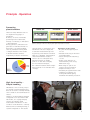
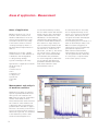
FAG Detector III –
The solution for monitoring and balancing
Principle · Operation
Preventing
plant downtime
There are many different reasons
for unplanned stoppage of
machinery.
However, a not inconsiderable
percentage can be attributed,
directly or indirectly, to imbalance
or misalignment.
During operation, imbalance can
generate considerable vibrations
that lead to secondary damage
such as premature bearing wear
or fatigue fractures. This results
in machine failure and thus
unplanned production shutdowns.
Reasons for unplanned downtime
Value OK
Prealarm
Main alarm
Symbols (smileys) in the device display allow rapid interpretation of results
rapid inspection of machinery and
assemblies. The user simply has
to start the measurement process
by pressing a few buttons and wait
until it is completed. Interpretation
of the measurement results is
carried out in a self-explanatory
manner by means of simple
symbols on the device display.
For more detailed analysis,
the software Trendline with comprehensive functions is available free
of charge.
Advantages of the system
– No prior knowledge required
for use
– Parallel monitoring of vibration
and temperature
– Static and dynamic balancing
on site
– Rapid, clear detection of
measurement points using
RFID technology
– Wide range of options for
analysis and presentation
– Simple and easy to use
– Excellent price/performance ratio
– Limitless possibilities for
development while giving
maximum investment protection.
High functionality –
Simple handling
FAG Detector III is a handy, easy to
use vibration measurement device
that can be used to reliably identify
such conditions and eliminate their
causes.
Thanks to its preinstalled standard
configurations in accordance with
ISO 10816, it is a plug-and-play
solution and allows initial
authoritative information on the
condition of the machine – entirely
without time-consuming training or
system configuration. This allows
1
Areas of application · Measurement
Areas of application
Machine vibrations are a good
indicator of the condition of a
machine. FAG Detector III can be
used to monitor vibrations, such
as machine vibrations according
to ISO 10816 and the condition
of rolling bearings by means of
the demodulated signal detection
method.
FAG Detector III is thus a highly
suitable device for the detection of
• imbalance and misalignment
• rolling bearing damage
• gearbox damage (tooth sets).
Typical areas of application include
the monitoring of
• pumps
• electric motors
• fans
• machine tools
• compressors
• gearboxes
• spindles
• etc.
For the measurement procedure,
the user either selects this measure ment location in the configuration
system of FAG Detector III or the
FAG Detector III automatically
identifies the measurement point
by means of RFID. Measurement is
then started. To begin with, the
speed is measured, which should
be constant during measurement
(at least 120 or, in the case of
ISO 10816, 600 min –1 ). The device
records the sensor signals according to the selected bandwidths
and calculates the parameters.
For each configuration, FAG Detector III compares the measured
parameters with the main alarm
limit values defined for this
measurement location.
If a threshold value is exceeded,
this is displayed directly on the
device. For conspicuous characteristic values, the causes can be
recognised from the demodulated
and raw signal spectrum.
Trend analysis gives an indication of
when an alarm will probably occur.
When an alarm is triggered, an
alarm report can be automatically
generated and printed out.
After reference measurement,
measurements should be carried
out at regular intervals. After this,
it is very easy to compare values
for the same speed, load etc.
Measurement and analysis
of machine condition
FAG Detector III picks up vibration
signals at predetermined measurement points and calculates the
RMS values for velocity, acceleration
and the demodulation curve.
These characteristic values describe
the condition of the machine and
components and are presented in
greater detail in the table on page 6.
The sensor should be positioned as
close as possible to the point to be
measured. In general, it is attached
to the machine by means of the
screw-mounted magnetic foot.
Presentation of measurement data in the Trendline software
2
Route planning · Bearing database
Route planning
The user can model the plant
structure on a PC using the
Trendline software. Within these
configurations, routes can be
defined, for example for individual
days of the week or by machine
type. Before measurement,
the selected route is transferred
to FAG Detector III. After a measurement round, all the recorded data
are transferred to the Trendline
software for evaluation, analysis
and presentation by means of
diagrams and tables.
Trendline –
Bearing database
The integrated bearing database
(approx. 20 000 bearings from
various manufacturers) allows
considerably simplified and
shortened analysis of the measured
data. In tandem with the Viewer,
the bearing database offers a
perfect combination for assessing
machine condition.
Significant features can be
recognised and allocated to the
appropriate components at first
sight. A separate bearing list can
be filed for each measurement
point. This offers the option of
checking several bearing overrolling
frequencies efficiently at one
measurement point. Each user can
expand the database by further
entries.
Bearing database
3
RFID · Run-up/coast-down · Report
Automatic detection of
measurement points – RFID
With the optional functionality
of automatic measurement point
detection*, recording of measurement values using FAG Detector III
is faster, more easier and userfriendly. With the aid of RFID
technology, the device automatically
detects the measurement points
if these are equipped with RFID
tags and jumps to the corresponding
point in the configuration.
Measurement of the wrong assembly
and erroneous allocation of
measurement points are thus
a thing of the past. The employee
only needs to start and store
measurement using FAG Detector III
– no other action is required.
Nothing could be simpler!
The RFID technology can be
easily retrofitted to existing
FAG Detector III devices.
Run-up/coast-down
Configurable report
Run-up/coast-down is used to
determine resonance points.
In a diagram (Bode plot), both the
amplitude and the phase during
run-up or coast-down are laid off
over speed and presented in
diagrammatic form in the Viewer.
The resonance ranges determined
can then be marked diagrammatically and allocated to any balancing
configuration. In the worst case,
balancing in the resonance range
can lead to machine damage.
A very useful feature of the
Trendline software is the report
generator. This offers maintenance
personnel in the company as well
as external service providers using
FAG Detector III the possibility of
achieving seamless documentation
of measurement results. The report
generator facilitates the preparation
of individual reports and allows,
for example, the incorporation of
customer logos. All the information
present in the system can be used
for the report, including time
signals, trend curves and alarm
data.
* This functionality is not available
worldwide. Please direct enquiries
to: [email protected]
Report generation
4
Features · Ordering designation and scope of delivery
Overview of advantages
• Complete package
• Static and dynamic balancing
(1 and 2 planes)
• Monitoring functions:
– ISO 10816
– temperature
– general vibration condition
– rolling bearing condition
– data collector for up to
1 600 measurement points
– storage of up to 300 time
signals
• Portable, handy, easy to use
diagnostic device
• Integrated database with
approx. 20 000 entries
• Operation with one hand using
21 keys
• Headset jack for acoustic noise
assessment
• Storage and display of up to
4 measurement values per
measurement point for straight forward condition assessment
• Automatic detection of measurement points (retrofittable)
• E-mail service
• PC software free of charge
DETECT3.BALANCE-KIT
Ordering designation and
scope of delivery
Detector III is available without and
with automatic measurement point
detection (RFID) (see footnote on
page 4). The Balancing Kit and
accessories are equally suitable
for both devices.
Ordering designation
DETECT3-KIT*
Scope of delivery:
• Basic device with rechargeable
battery
• Acceleration sensor with
magnetic foot
• Temperature sensor
• Charger
• PC data cable (serial/USB)
• User manual
• Protective bag with holder
for temperature sensor
• PC software Trendline
• Case
Ordering designation
DETECT3-KIT-RFID**
Scope of delivery:
• As DETECT3-KIT
• RFID Reader
(integrated in basic device)
• 5 RFID tags
Ordering designation
DETECT3.BALANCE-KIT***
Scope of delivery:
• Acceleration sensor with
magnetic foot and sensor cable
• Trigger sensor
(optical and inductive)
• Balance
• Magnetic holder for trigger sensor
• Extension for magnetic holder
• Cable for trigger sensor
(length 10 m)
• Reflex mark for trigger sensor
• Dongle for activation of balancing
function
• Case
Accessories
• Sensor extension cables for
lengths of 5 m and 15 m are
available on request
• Further RFID tags are available
on request
• Charging station
In some countries, different
ordering designations are still
in use:
* FIS.DETECTORIII.KIT
** FIS.DETECTORIII.KIT.RFID
*** FIS.DETECTORIII.BALANCING.KIT
DETECT3-KIT
5
Selection of parameters
Selection of parameters
Possible characteristic values and signal curves
for each measurement point
Measurement range/resolution Frequency range
Display
Characteristic value: vibration velocity to ISO 10816
(VDI 2056)
(broadband RMS value for velocity)
for general assessment of machine condition
to ISO 10816
ISO 10816
0 to 5,52 m/s3) at 10 Hz
0 to 55,2 mm/s3) at 1 kHz
10 Hz to 1 kHz
Detector and PC
Characteristic value: velocity (freely selectable)
(RMS value for velocity,
e.g. for detection of imbalance and misalignment)
Vsel
0 to 5,52 m/s3) at 10 Hz
0 to 55,2 mm/s3) at 1 kHz
Freely selectable
up to set TP1)
(max. 20 kHz)
Detector and PC
Characteristic value: acceleration
(broadband RMS value for acceleration,
e.g. for monitoring of gearboxes)
Aeff
0 to 37 g3)
2 kHz –
up to set TP1)
(max. 20 kHz)
Detector and PC
Characteristic value: acceleration (freely selectable)
(e.g. for selective gear tooth monitoring)
Asel
0 to 37 g3)
Freely selectable
up to set TP1)
(max. 20 kHz)
Detector and PC
Characteristic value: demodulated signal
(RMS value of demodulated signal up to 100/1000 Hz,
e.g. for monitoring of rolling bearing condition)
Deff
0 to 37 g3)
Freely selectable
up to set TP1)
(max. 20 kHz)
Detector and PC
Characteristic value: demodulated signal (freely selectable) Dsel
0 to 37 g3)
(e.g. for selective monitoring of rolling bearing condition)
Freely selectable
up to set TP1)
(max. 20 kHz)
Detector and PC
Time signal of acceleration up to
set low-pass cut-off frequency, 4 096 or 8 192 values
±50 g3)
0,1 Hz to 20 kHz2)
PC
Demodulated time signal up to set
low-pass cut-off frequency, 4 096 or 8 192 values
±50 g3)
0,1 Hz to 20 kHz2)
PC
Frequency spectrum (Fourier transform)
of velocity up to set low-pass cut-off frequency
±5,52 m/s3), resolution:
TP · 2,56 / number of values4)
(0,0625 Hz to 12,5 Hz)
0,3 Hz to 20 kHz2)
PC
Frequency spectrum (Fourier transform)
of velocity up to set low-pass cut-off frequency
±50 g3), resolution:
TP · 2,56 / number of values4)
(0,0625 Hz to 12,5 Hz)
0,1 Hz to 20 kHz2)
PC
Frequency spectrum (Fourier transform)
of demodulated frequency alternatively up to set
low-pass cut-off frequency
±25 g3), resolution:
TP · 2,56/ number of values4)
(0,0625 Hz to 12,5 Hz)
0,1 Hz to 20 kHz2)
PC
Measurement point temperature
Temp = –20 °C to +550 °C
–
Detector and PC
Crest factor
–
Calculation from time Detector and PC
signal for acceleration
(up to TP)
Speed
120 to 10 000 min–1
2 Hz to 166Hz
Detector and PC
1)
TP = low-pass cut-off frequency (200, 500 Hz, 1, 2, 5, 10, 20 kHz)
Lower limit frequency as a function of set low-pass cut-off frequency (lower limit frequency = TP/number of lines · 2,56)
3) 100 mV/g – sensor
4) Number of values: 4 096 (at 1600 FFT lines) or 8 192 (at 3 200 FFT lines)
2)
On the PC, the user can specify for each measurement point whether and under what conditions certain time signals are to be stored.
Three different time signals can be measured:
– 2 ~ acceleration (0,1 Hz to TP; scan rate = 2,56 · TP; 0,1 Hz to TP; scan rate = 2,56 · TP). One is used for calculating the velocity
spectrum.
– Demodulated signal (0 Hz to TP; scan rate = 2,56 · TP).
6
Technical data
Data collection
Measurement ranges
Acceleration/velocity 0,1 Hz to TP 1)
0,1 Hz to 200 Hz; 0,1 Hz to 500 Hz; …
Demodulated signal 0 Hz to TP 1)
Low-pass cut-off frequencies 200, 500 Hz, 1, 2, 5, 10, 20 kHz
High-pass (demodulated signal branch) 750 Hz
Temperature –20 °C to +550 °C (temperature range as a function of sensor
used, freely configurable input)
Characteristic values
A eff
(2 kHz to TP 1) ), RMS value for acceleration
A sel
RMS value for acceleration in freely definable frequency range
ISO 10816 (10 kHz to 1 kHz), RMS value for velocity
V sel
RMS value for velocity in freely definable frequency range
(frequency band as a function of TP 1) )
D eff
RMS value for demodulated signal
D sel
RMS value for demodulated signal in freely definable
frequency range
Crest factor, speed, temperature, universal characteristic value
Window function
Hanning
Averaging in frequency range
1–9 (FFT, characteristic values per channel)
Linear
Sampling rate
max. 51,2 kHz, as a function of the set TP 1)
A/D converter
16 Bit (autoranging), dynamic range >90 db
Frequency resolution
1 600, 3 200 lines (0,0625 Hz to 12,5 Hz as a function of the set TP 1) )
Automatic
measurement point detection
RFID 13,56 MHz, ISO 15693, compatible with RFID tags of stated
specification
Ramp-up/Coast-down
Configurable (1024, 2048 and 4096 measurement points)
Automatic start/stop function
Inputs
2 ~ BNC jacks (multiplexer)
ICP (4,7 mA), steplessly adjustable sensitivity, sensor tester
AC/DC ±5 V, impedance >100 kT
1 ~ AUX
Tachometer input 5 to 24V, &λτ;10 000 min –1
(rising or falling flank selectable)
IR temperature sensor ±5 V, impedance >100 kT
(freely configurable)
Battery charger
Outputs
Headset (demodulated signal)
RS 232 for data transmission (38,4 kps, 57,6 kps)
AUX: supply for trigger sensor (5 V max. 200 mA, 12 V max. 50 mA)
1)
TP = low-pass cut-off frequency
7
Technical data
Balancing
1 or 2 plane balancing
Up to 4 sensor positions
Weight positions: Continuous (0 to 359°) or discrete (4 to 99 positions)
Removal of weights: yes/no
Balancing measurement type
Acceleration, velocity, travel
Measurement
peak, peak-to-peak, RMS
Balance units
g, mm/s, inch/s, μm, mil
Weight units
gr., oz. (up to 9 999,99 gr. or oz.)
General
8
Separate measurements
Temperature, speed, headset (demodulated signal)
Keyboard
Soft keyboard with 21 keys
Display
Illuminated graphic display (LCD) 128 ~ 64 pixels, 55 mm ~ 33 mm
Memory
1 600 measurement points plus 270 time signals (maximum 300 time signals)
Power supply
NiMh 2 100 mAh (low discharge), voltage 6 V
Dimensions and mass
230 ~ 70(53) ~ 45(53) mm (L ~ B ~ H), approx. 500 g
(including rechargeable battery)
Temperature range
0 °C to 50 °C (working temperature)
Operating life
approx. 6 to 8 hours continuous operation
Housing
ABS, IP 40
Protective bag
Two compartments, black nylon, carry strap
EMC standards
ETSI EN 301 489, ETSI EN 300 330, EN61000-6-2, EN61000-6-4, EN60950-1,
FCC Part 15
Firmware
Free of charge firmware updates on the Internet
Available languages:
German, English, Finnish, French, Italian, Dutch, Portuguese, Swedish,
Slovenian, Spanish and Turkish
Software
Trendline (updates on the Internet)
Compatible with Windows XP, Windows 7 64-Bit
Available in: German, English, French, Portuguese and Spanish
– Configuration of FAG Detector III via RS 232 interface
– Bearing database of approx. 20 000 bearings
– Graphic presentation of measurement values and curve
– Trend analysis
– Presentation of time signals and FFT
– Display of balancing in tabular and diagrammatic format
– Configurable report generator
Everything from a single source –
Customised monitoring solutions for everyone
Everything from a
single source –
Customised monitoring
solutions for everyone
The Service Sector of Schaeffler
Group Industrial is a full service
supplier in the field of conditionbased maintenance. With the
sourcing of high quality FAG
products, the customer thus gains
access to a range of productrelated services (see diagram).
Based on many years’ experience,
the Schaeffler Group knows that
customers wishing to change to
the concept of condition monitoring
have differing needs and
requirements. It therefore offers,
in relation to the product and
service range, both standard
training and customer-specific
solutions.
The service portfolio in the field
of regular condition monitoring
encompasses solutions that introduce the customer step by step to
the overall subject. This makes it
possible even for beginners to carry
out measurements for themselves
and gain information about the
condition of machinery. At the same
time, the solutions also offer the
maximum potential for development,
right up to the level of vibration
expert.
It is of course the customer who
decides which of the available
services he wishes to use. In this
way, he can for example decide
how far into the subject of vibration
monitoring he wishes to progress.
Whichever service is selected,
the Schaeffler team of experts is
available to assist the customer at
any time. If you have any further
questions on our services, please
contact us direct or visit our
website www.FAG-DetectorIII.com
Services for FAG Detector III
9
Schaeffler Technologies
TPI WL 80-64 / 2011031.5 / Printed in Germany by tümmels
GmbH & Co. KG
Postfach 1260
Every care has been taken to ensure the
97419 Schweinfurt
correctness of the information contained
Germany
in this publication but no liability can be
Georg-Schäfer-Straße 30
97421 Schweinfurt
accepted for any errors or omissions.
We reserve the right to make technical
changes.
Germany
© Schaeffler Technologies GmbH & Co. KG
Phone
+49 2407 9149-66
Fax
+49 2407 9149-59
E-Mail
[email protected]
Internet www.schaeffler-iam.com
Issued: 2011, March
This publication or parts thereof may not
be reproduced without our permission.
TPI WL 80-64/4 EA