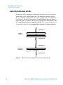
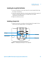
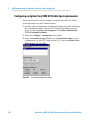
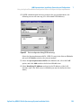
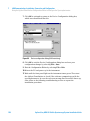
1
Agilent Cary 8454 UV-Visible Spectroscopy System Installation Guide Notices © Agilent Technologies, Inc. 2002, 2003-2008, 2011, 2013, 2014 No part of this manual may be reproduced in any form or by any means (including electronic storage and retrieval or translation into a foreign language) without prior agreement and written consent from Agilent Technologies, Inc. as governed by United States and international copyright laws. Manual Part Number G1115-90053 Edition 08/14 Agilent Technologies, Australia (M) Pty Ltd 679 Springvale Road Mulgrave, Victoria, Australia 3170 Research Use Only This product may be used as a component of an in vitro diagnostic system if the system is registered with the appropriate authorities and complies with the relevant regulations. Otherwise, it is intended only for general laboratory use. Software Revision This handbook is for B.05.xx revisions of the Agilent ChemStation software, where xx is a number from 00 through 99 and refers to minor revisions of the software that do not affect the technical accuracy of this handbook. Microsoft ® is a U.S. registered trademark of Microsoft Corporation. Warranty The material contained in this document is provided “as is,” and is subject to being changed, without notice, in future editions. Further, to the maximum extent permitted by applicable law, Agilent disclaims all warranties, either express or implied, with regard to this manual and any information contained herein, including but not limited to the implied warranties of merchantability and fitness for a particular purpose. Agilent shall not be liable for errors or for incidental or consequential damages in connection with the furnishing, use, or performance of this document or of any information contained herein. Should Agilent and the user have a separate written agreement with warranty terms covering the material in this document that conflict with these terms, the warranty terms in the separate agreement shall control. defined in FAR 52.227-19(c)(1-2) (June 1987). U.S. Government users will receive no greater than Limited Rights as defined in FAR 52.227-14 (June 1987) or DFAR 252.227-7015 (b)(2) (November 1995), as applicable in any technical data. Safety Notices CAUTION A CAUTION notice denotes a hazard. It calls attention to an operating procedure, practice, or the like that, if not correctly performed or adhered to, could result in damage to the product or loss of important data. Do not proceed beyond a CAUTION notice until the indicated conditions are fully understood and met. Technology Licenses The hardware and/or software described in this document are furnished under a license and may be used or copied only in accordance with the terms of such license. Restricted Rights Legend If software is for use in the performance of a U.S. Government prime contract or subcontract, Software is delivered and licensed as “Commercial computer software” as defined in DFAR 252.227-7014 (June 1995), or as a “commercial item” as defined in FAR 2.101(a) or as “Restricted computer software” as defined in FAR 52.227-19 (June 1987) or any equivalent agency regulation or contract clause. Use, duplication or disclosure of Software is subject to Agilent Technologies’ standard commercial license terms, and non-DOD Departments and Agencies of the U.S. Government will receive no greater than Restricted Rights as WA R N I N G A WARNING notice denotes a hazard. It calls attention to an operating procedure, practice, or the like that, if not correctly performed or adhered to, could result in personal injury or death. Do not proceed beyond a WARNING notice until the indicated conditions are fully understood and met. Agilent Cary 8454 UV-Visible Spectroscopy System Installation Guide In This Guide… This handbook describes what you have to do to install your UV-Visible spectroscopy system. Most of the handbook deals with installing a complete system, that is, the spectrophotometer, computer and printer. However, in the second half of this handbook you will find additional information about installing accessories, accessory boards, GPIB connections and configuration, and software installation. 1 Fast Installation Use this chapter as an overview of the different actions you must perform to install your UV-Visible spectroscopy system. If you are an experienced user of analytical equipment from Agilent Technologies, this may be all you need. If you need more information, this chapter guides you to other relevant areas in this or another handbooks. 2 Installation and Start Up Use this chapter if you need more detailed information about the installation process. 3 Good Measurement Practices Use this chapter if you require information about general operating conditions to perform accurate and reliable measurements, for example, handling samples, solvents and cells. 4 Installing Accessories This chapter describes how to install the simple mechanical and optical accessories that are available to expand the capabilities of your UV-Visible spectrophotometer. 5 Installing the UV-Visible Software This chapter describes what your computer requires, and what you must do to install the software. Agilent Cary 8454 UV-Visible Spectroscopy System Installation Guide 3 6 GPIB Communication, Connections and Configuration This chapter describes how to set the select code, how to install an GPIB card in your computer and how to change the GPIB address of your spectrophotometer. 7 LAN Communication, Installation, Connection and Configuration This chapter describes how to set up LAN communication between your Agilent ChemStation and your UV-Visible spectrophotometer. A Safety Information This chapter contains relevant safety information. 4 Agilent Cary 8454 UV-Visible Spectroscopy System Installation Guide Contents 1 Fast Installation 11 Installing Preconfigured Agilent Cary 8454 UV-Visible Systems 12 Installing Non-Preconfigured Agilent Cary 8454 UV-Visible Spectrophotometer Systems 13 Installing Software Only 2 15 Installation and Start Up 17 Site Requirements for Your Spectrophotometer Power considerations 19 Power cords 20 Space 20 Environment 21 Unpacking Your Spectrophotometer 19 22 Installing your UV-Visible Spectrophotometer Instrument overview 23 Setting up the Spectrophotometer 27 23 Installing Your Computer 29 Setting up the computer 29 Starting the Spectrophotometer Turning On 30 Instrument Warm-up 32 30 Starting the Agilent ChemStation Software Operational Checkout 33 33 Agilent Cary 8454 UV-Visible Spectroscopy System Installation Guide 5 Contents 3 Good Measurement Practices 35 General Considerations 36 Spectrophotometer Design 36 Making Measurements 36 Sample Cell or Cuvette Material 37 Optical Specifications of Cells 38 Apertured Cells or Cuvettes 39 Flow Cells 40 Handling and Maintaining Cells or Cuvettes Solvents 43 Sample Preparation 44 Photosensitive Samples 45 Stirring and Temperature Control 45 Checklist for Best Results 46 Inserting a Cell 4 41 48 Installing Accessories 49 Thermostattable Cell Holder 50 Installing a Thermostattable Cell Holder 51 Cell Stirring Module 52 Installing the Cell Stirring Module 53 Tubing Connections and Operation 54 Long Path Cell Holder 56 Installing the Long Path Cell Holder Installing a Sample Cell 57 Optical Filter Wheel 59 Installing the Filter Wheel Assembly Removing the Filter Wheel Assembly 5 Installing the UV-Visible Software 61 62 63 Agilent ChemStation Computer Details 6 57 64 Agilent Cary 8454 UV-Visible Spectroscopy System Installation Guide Contents Minimum PC Requirements for Agilent ChemStation 64 Installing the Agilent ChemStation Using the DVD 67 Overview 67 Uninstalling Pre-existing Agilent UV-Visible ChemStation Software Installation Procedure 68 Monitor Configuration 72 Configuring Your System 73 6 GPIB Communication, Connections and Configuration GPIB Communication 78 Operating System-Instrument Compatibility Installing an GPIB Interface 79 GPIB Cabling 80 77 78 Installation of the Agilent GPIB Communication Library Installing New IO Libraries 82 Configuring the Agilent 82350 GPIB Interface 67 82 86 Configuring the Agilent 82357 USB - GPIB Interface 92 Upgrading Existing IO Libraries 101 Upgrading IO Libraries 101 Working with your Agilent IO Libraries 102 Troubleshooting 103 Missing files during installation 103 Problems with Plug and Play option GPIB cards 105 Changing the GPIB Address of the Spectrophotometer GPIB Address Settings 109 7 107 LAN Communication, Installation, Connection and Configuration Installing and Configuring TCP/IP on the PC Installation of the TCP/IP protocol 112 Agilent Cary 8454 UV-Visible Spectroscopy System Installation Guide 111 112 7 Contents Installing the LAN Interface in your UV-Visible Spectrophotometer Connecting the Spectrophotometer to the PC 116 Single Instrument Installation 116 Multiple Instrument Installation 116 Setting the IP Address of the Spectrophotometer 115 117 Using the Agilent BootP Service 118 What is the Agilent BootP Service? 118 Addresses 119 Using the Agilent BootP Service Program 120 Configure the Agilent BootP Service Program 121 Configure the Agilent BootP Service 123 Configuring the G1369C LAN Card Using BootP 125 Using the Agilent ChemStation Configuration Editor to Configure the Spectrophotometer 127 What is the Agilent ChemStation Configuration Editor? 127 Configuring an Agilent Cary 8454 UV-Visible Spectrophotometer 128 Troubleshooting LAN Communication 131 Power failure reported on the Agilent ChemStation 131 Frequent buffer overrun in Agilent Cary 8454 logbook 132 A Safety Information 133 Safety Information 134 Warning Symbols 134 Precautions 136 Solvent Information 137 Flow Cells 137 Solvents 137 Other Precautions 139 Protective Earth 139 Disconnecting Device 139 8 Agilent Cary 8454 UV-Visible Spectroscopy System Installation Guide Contents Allowing Hot Instrument to Cool 140 Environmental Conditions and Power Requirements Installation category 142 Pollution level 142 Electrical Power 142 Regulatory Information 143 CE Compliance 143 Electromagnetic Compatibility Agilent Technologies on the Internet Index 141 143 145 147 Agilent Cary 8454 UV-Visible Spectroscopy System Installation Guide 9 Contents 10 Agilent Cary 8454 UV-Visible Spectroscopy System Installation Guide Agilent Cary 8454 UV-Visible Spectroscopy System Installation Guide 1 Fast Installation Installing Preconfigured Agilent Cary 8454 UV-Visible Systems 12 Installing Non-Preconfigured Agilent Cary 8454 UV-Visible Spectrophotometer Systems 13 Installing Software Only 15 Installation is straightforward, but if you have difficulties, or need more information, references to detailed installation information are given. Use this chapter if you are: • installing a preconfigured UV-Visible spectroscopy system from Agilent (including spectrophotometer, computer and software), • installing a UV-Visible spectroscopy system not purchased as a preconfigured system, or • installing software only. Agilent Technologies 11 1 Fast Installation Installing Preconfigured Agilent Cary 8454 UV-Visible Systems Installing Preconfigured Agilent Cary 8454 UV-Visible Systems If you have purchased one of these systems, the software is pre-installed and preconfigured. You need only install and switch on the hardware. ✔ Ensure you have space and an appropriate power supply. For more information, see “Site Requirements for Your Spectrophotometer” on page 19. ✔ Unpack the system—check for damage and contents against packing list. For more information, see “Unpacking Your Spectrophotometer” on page 22. ✔ Install your UV-Visible spectrophotometer. • Connect line power to the rear. • Connect the waste tubing underneath the sample pan. For more information, see “Installing your UV-Visible Spectrophotometer” on page 23. ✔ Install your computer and printer. • Connect the keyboard and mouse. • Connect the monitor to line power and to the computer. • Connect the printer to line power and to the computer. • Connect the computer to the spectrophotometer with the GPIB or LAN cable. For more information, see “Installing Your Computer” on page 29 and Chapter 7, “LAN Communication, Installation, Connection and Configuration”. ✔ Switch on the spectrophotometer (make sure the sample area is clear), wait 2 minutes for the lamps to ignite. When you are ready to operate your spectrophotometer, switch on the computer and printer. For more information, see “Starting the Spectrophotometer” on page 30. 12 Agilent Cary 8454 UV-Visible Spectroscopy System Installation Guide Fast Installation Installing Non-Preconfigured Agilent Cary 8454 UV-Visible Spectrophotometer Systems 1 Installing Non-Preconfigured Agilent Cary 8454 UV-Visible Spectrophotometer Systems You must install and configure the software. In addition, you may need to install and configure an instrument communication interface such as the GPIB PCI interface card. ✔ Ensure you have space and an appropriate power supply. For more information, see “Site Requirements for Your Spectrophotometer” on page 19. ✔ Unpack the system - check for damage and contents against packing list. For more information, see “Unpacking Your Spectrophotometer” on page 22. ✔ Install your UV-Visible spectrophotometer. • Connect the line power to the rear. • Connect the waste tubing underneath the sample pan. For more information, see “Installing your UV-Visible Spectrophotometer” on page 23. ✔ If your computer and printer are not supplied by Agilent, ensure that the requirements for proper operation of the software are met. For more information, see “Minimum PC Requirements for Agilent ChemStation” on page 64. ✔ Install the GPIB interface board in your computer. For more information, see “Installing an GPIB Interface” on page 79. ✔ Install your computer and printer. • Connect the keyboard and mouse. • Connect the monitor to the power supply and to the computer. • Connect the printer to the power supply and to the computer. • Connect the computer to the spectrophotometer with the GPIB cable. Agilent Cary 8454 UV-Visible Spectroscopy System Installation Guide 13 1 Fast Installation Installing Non-Preconfigured Agilent Cary 8454 UV-Visible Spectrophotometer Systems For more information, see “Installing Your Computer” on page 29. ✔ Switch on the spectrophotometer (make sure sample area is clear) and wait two minutes for the lamps to ignite. When you are ready to operate your spectrophotometer, switch on the computer and printer. For more information, see “Starting the Spectrophotometer” on page 30. ✔ Install the Agilent ChemStation software. For more information, see “Installing the Agilent ChemStation Using the DVD” on page 67. ✔ From the Windows Start menu, start the Agilent ChemStation software. For more information, see “Starting the Agilent ChemStation Software” on page 33. ✔ Ensure that your software and spectrophotometer operate properly by taking a blank measurement or performing the automatic self-test in the diagnostic section of your software. For more information, see “Operational Checkout” on page 33. ✔ If you need information about solvents, sample preparation, blank measurements, cuvette handling or how to insert a cuvette, see Chapter 3, “Good Measurement Practices”. ✔ Install any accessories. For simple accessories see Chapter 4, “Installing Accessories”; for complex accessories, see the instructions supplied with the accessory or the Installation and Maintenance section of the Agilent ChemStation online help. 14 Agilent Cary 8454 UV-Visible Spectroscopy System Installation Guide Fast Installation Installing Software Only 1 Installing Software Only ✔ Unpack the software—check for damage and check the contents against the packing list. ✔ Ensure that your computer and printer meet the requirements for proper operation of the software. For more information, see “Minimum PC Requirements for Agilent ChemStation” on page 64. ✔ Switch on the spectrophotometer (make sure the sample area is clear) and wait two minutes for the lamps to ignite. When you are ready to operate your spectrophotometer switch on the computer and printer. ✔ From the Windows menu install the Agilent ChemStation software. For more information, see “Installing the Agilent ChemStation Using the DVD” on page 67. ✔ From the Windows Start menu start the Agilent ChemStation software. For more information, see “Starting the Agilent ChemStation Software” on page 33. ✔ Ensure that your software and spectrophotometer operate properly, by taking a blank measurement or by performing the automatic self-test in the diagnostic section of your software. For more information, see “Operational Checkout” on page 33. Agilent Cary 8454 UV-Visible Spectroscopy System Installation Guide 15 1 16 Fast Installation Installing Software Only Agilent Cary 8454 UV-Visible Spectroscopy System Installation Guide Agilent Cary 8454 UV-Visible Spectroscopy System Installation Guide 2 Installation and Start Up Site Requirements for Your Spectrophotometer 19 Unpacking Your Spectrophotometer 22 Installing your UV-Visible Spectrophotometer 23 Installing Your Computer 29 Starting the Spectrophotometer 30 Starting the Agilent ChemStation Software 33 Operational Checkout 33 The following topics are covered in this section: • “Site Requirements for Your Spectrophotometer” on page 19 contains information about electrical requirements such as power lines, power cords, etc. It also gives recommendation for minimum available bench space and environmental conditions in the laboratory. • “Unpacking Your Spectrophotometer” on page 22 contains information about what to do when the packing material is damaged or the shipment is incomplete. It includes a list of the items which are supplied with the instrument and computer. • “Installing your UV-Visible Spectrophotometer” on page 23 gives an overview of the instrument and explains buttons, indicators and the line power switch. It explains where and how to connect line power, communications and waste drain tubing. • “Installing Your Computer” on page 29 describes how to install the computer and peripherals, e.g. monitor, mouse, keyboard and printer. Because the UV-Visible operating software comes already installed when the system has been ordered as a bundle, this topic is covered in Chapter 6, “GPIB Communication, Connections and Configuration”. Agilent Technologies 17 2 Installation and Start Up • “Starting the Spectrophotometer” on page 30 describes the turn-on procedure for the spectrophotometer and the warm up time required to fulfill all specifications. • “Starting the Agilent ChemStation Software” on page 33 describes how you start Windows from the MS-DOS operating system and how you start your Agilent ChemStation software. • “Operational Checkout” on page 33—use this section to ensure that your spectrophotometer, computer and the UV-Visible operating software is in proper operating condition. There is an optional automated self-test which can be used for a quick check of the spectrophotometer. This self-test can only be executed after the instrument has warmed up for at least one hour. 18 Agilent Cary 8454 UV-Visible Spectroscopy System Installation Guide Installation and Start Up Site Requirements for Your Spectrophotometer 2 Site Requirements for Your Spectrophotometer Power considerations Your spectrophotometer can operate on a line voltage of 100–240 V AC with a line frequency of 50 or 60 Hz. Maximum power consumption is 220 VA. The instrument power supply accepts any line voltage supplied in the above mentioned range. Consequently there is no voltage selector in the rear of the spectrophotometer. There are no externally accessible fuses, because automatic electronic fuses are implemented in the power supply. WA R N I N G To disconnect the instrument from line power, disconnect the power cord from the supply. The power supply still uses some power, even if the power switch on the front panel is turned off. The computer and InkJet or LaserJet printers accept a nominal line voltage of 110 or 220 V AC with a line frequency of 50 or 60 Hz. For more information, see the documentation that comes with your computer and/or printer. WA R N I N G Connecting your instrument to a line voltage that is higher than specified causes a shock hazard, and damage may occur to your instrument. Agilent Cary 8454 UV-Visible Spectroscopy System Installation Guide 19 2 Installation and Start Up Site Requirements for Your Spectrophotometer Power cords Different power cords are offered as options with the spectrophotometer. The female end of each of the power cords is identical. This connects to the power-input socket at the rear of the spectrophotometer. The male end of each of the power cords is different and designed to match the wall socket of a particular country or region. NOTE WA R N I N G Do not replace the mains power cord with one that is inadequately rated. When replacing the mains power cord, use only a mains power cord with a rating equivalent to the one supplied with the instrument. See the instrument installation guide for detailed mains power cord rating information. Always operate your instrument from a power outlet which has a ground connection. Always use the power cord designed for your region. Do not position the equipment so that it is difficult to operate the disconnecting device. Space The spectrophotometer is 34.4 cm (13.5 inches) wide, 56.0 cm (22.0 inches) deep and 18.5 cm (7.3 inches) high (see Figure 1 on page 24). It weighs 14 kg (30.86 lbs) and will fit on almost any desk or laboratory bench. It needs an additional 2.5 cm (1.0 inches) of space on either side to allow for the circulation of air for cooling, and approximately 8 cm (3.1 inches) in the rear for electrical connections. The computer, including the keyboard, is approximately 50 cm (19.7 inches) wide and 60 cm (23.6 inches) deep. Additional space is required for accessories like pumps and autosamplers. 20 Agilent Cary 8454 UV-Visible Spectroscopy System Installation Guide Installation and Start Up Site Requirements for Your Spectrophotometer 2 Environment Your spectrophotometer will operate within specifications at ambient temperatures of 0 to 40°C (32 to 104°F). WA R N I N G If you use the instrument at environmental temperatures higher than 50°C (122°F), the rear of the instrument may get hot. The spectrophotometer can be shipped or stored where the ambient temperature is between -40 and 70°C (-4 and 158°F). WA R N I N G Do not store, ship or use your instrument under conditions where temperature fluctuations could cause condensation within the instrument. Condensation will damage the electronics. If your instrument was shipped in cold weather, leave it in its box and allow it to warm up slowly to room temperature to avoid condensation. You can operate your spectrophotometer in environments with relative humidity up to 95 % (non-condensing) provided the temperature is between 25 and 40°C (77 to 104°F). Avoid air circulation of varying temperatures (like from refrigerators or air conditioners) and exposure to direct sun light to ensure the instrument operates within performance specifications. Your spectrophotometer can be stored at altitudes up to 4,600 m (14,950 ft.) and operated at altitudes up to 2,000 m (6,500 ft.). Agilent Cary 8454 UV-Visible Spectroscopy System Installation Guide 21 2 Installation and Start Up Unpacking Your Spectrophotometer Unpacking Your Spectrophotometer Upon receipt of your spectrophotometer, computer and printer, inspect the shipping containers for any signs of damage. If the containers or cushioning material are damaged, save them until the contents have been checked for completeness and the spectrophotometer, computer or printer have been mechanically and electrically checked. If the shipping container or cushioning material is damaged, notify the carrier as well as Agilent Technologies. Save the shipping material for the carrier’s inspection. Check the contents of the shipping container against the list below. If any items are missing or obviously damaged, call Agilent Technologies. ✔ Unpack the spectrophotometer. You should have the following components: • Power cord to connect the spectrophotometer to line power. • LAN Interface, if you connect the spectrophotometer through a LAN • Waste tubing to connect the sample pan of your spectrophotometer to a waste container. • Checkout sample (caffeine solution). ✔ Unpack the computer and its accessories. You should have the following components: • Computer and power cable • Keyboard • Mouse • Display unit, connecting cable and power cable • USB to GPIB Interface, if you connect the spectrophotometer through GPIB • Printer, connecting cable and power cable • Printer accessories, for example, ink cartridge in case of a DeskJet printer 22 Agilent Cary 8454 UV-Visible Spectroscopy System Installation Guide Installation and Start Up Installing your UV-Visible Spectrophotometer 2 Installing your UV-Visible Spectrophotometer Your spectrophotometer is very easy to install. This section provides an overview of the instrument and a checklist of the main installation procedure. If you have accessories for the spectrophotometer which are not covered in this section, see Chapter 4, “Installing Accessories” or refer to the documentation that was delivered with your accessories for detailed information. Instrument overview The front view of the spectrophotometer is shown in Figure 1 which shows the sample compartment open. Unlike conventional instruments the UV-Visible spectrophotometer does not suffer from ambient stray light. The open sample area makes it easier to access it generally and to connect tubing to a flow cell or thermostattable cell holder. The spectrophotometer is shipped with the standard single-cell cell holder already in place. Standard and accessory cell holders can be removed and replaced in seconds with few or no tools. Agilent Cary 8454 UV-Visible Spectroscopy System Installation Guide 23 2 Installation and Start Up Installing your UV-Visible Spectrophotometer Pushbuttons Line power switch with green light Indicator Figure 1 Front view of the Agilent Cary 8454 UV-Visible spectrophotometer The line power switch is located at the lower left part of the instrument. Pressing it in turns on the instrument. It stays pressed in and shows a green light when the instrument is turned on. When the line power switch stands out and the green light is off, the instrument is turned off. On the front panel of the spectrophotometer is an indicator which will display different colors depending of the actual condition of the instrument. • Green: the instrument is ready to measure. • Green, blinking: the instrument is measuring. • Yellow: the instrument is in busy state, for example, turning one of the lamps on or if both lamps are switched off. • Red: Error condition, that is, the spectrophotometer does not pass one of the self tests which are run when the spectrophotometer is turned on or an error occurred during operation. In this case the UV-Visible operating software gives a detailed error message and possible explanations are in the online help system. Additionally the Reference Manual gives information about troubleshooting. 24 Agilent Cary 8454 UV-Visible Spectroscopy System Installation Guide Installation and Start Up Installing your UV-Visible Spectrophotometer 2 • Red, blinking: Error condition of the spectrophotometer processor system. Because in this case there is no communication with the computer there will be no error message. The online help system and the Reference Manual gives more information about troubleshooting. The four pushbuttons on the front panel cause the following actions to be performed and the resulting data being sent to the computer. • blank: the instrument takes a blank measurement, that is, a reference measurement of solvent without the analyte. This is used in all subsequent sample measurements until a new blank measurement is taken. A baseline spectrum is displayed on the computer. • sample: the instrument takes a sample measurement or starts a series of measurements. This depends on the parameters set in your software. • standard: the instrument takes a measurement of a standard. Additional information, such as concentration and so on, have to be entered in the operating software. • stop: the instrument and/or software aborts any ongoing activity and returns to a to measure state. All connections are made at the rear of the spectrophotometer, see Figure 2. GPIB connector and switches Remote connector MIO slot for LAN interface Multicell transport connector GP-IO connector Line connector RS 232 connector Figure 2 Rear view of the Agilent Cary 8454 UV-Visible spectrophotometer Agilent Cary 8454 UV-Visible Spectroscopy System Installation Guide 25 2 Installation and Start Up Installing your UV-Visible Spectrophotometer • The multi-cell connector allows you to connect the cable which comes from the multicell transport. • The GPIO (general purpose input/output) connector allow you to connect your sipper and autosampler or other accessories. • The remote connector may be used in combination with other analytical instruments from Agilent Technologies if you want to use features such as common shut down, prepare etc. • The RS 232 connector may be used to control the spectrophotometer from a computer through RS 232 connection, using appropriate software (for future use). This connector needs to be activated by the configuration switch module next to the GPIB connector. The software needs the appropriate drivers to support this communication. See your software documentation for further information. • The GPIB connector is used to connect the spectrophotometer with a computer. The 8-bit configuration switch module next to the GPIB connector determines the GPIB address of your spectrophotometer. The switches are preset to a default address recognized by the operating software from Agilent Technologies. • The MIO slot for the Lan interface. • The accessory board slot is reserved for future use. • The power input socket accepts a line voltage of 100–240 V AC with a line frequency of 50 or 60 Hz. Maximum power consumption is 220 VA. There is no voltage selector on your spectrophotometer because the power supply has wide ranging capability. There are no externally accessible fuses, because automatic electronic fuses are implemented in the power supply. The security lever at the power input socket prevents that the spectrophotometer cover is taken off when line power is still connected. On the right side of the instrument there is a door for exchanging the lamps. Behind this plastic door there is another sheet metal door. Two independent safety light switches are implemented. They automatically turn off the lamps when the sheet metal door is opened. 26 Agilent Cary 8454 UV-Visible Spectroscopy System Installation Guide Installation and Start Up Installing your UV-Visible Spectrophotometer 2 Setting up the Spectrophotometer Connecting Your Spectrophotometer via GPIB to the Computer 1 Identify the spectrophotometer’s configuration switch module, see Figure 3. For GPIB operation the default address is 25, that is, all switches are in the down position except for the switches 4, 5 and 8 which are in up the position, resulting in a pattern 00011001 (where 0 means down and 1 means up). No two instruments or accessories may share the same GPIB address. For alternate switch settings, see Chapter 6, “GPIB Communication, Connections and Configuration”. 1 2 3 Figure 3 4 5 6 7 8 Configuration switch module 2 Connect the GPIB cable to the GPIB connector at the rear of the spectrophotometer. Connecting your Spectrophotometer via LAN to the Computer see Chapter 7, “LAN Communication, Installation, Connection and Configuration” Connecting Power to Your Spectrophotometer See Figure 2 on page 25. 1 Your line voltage must be between 100–240 V AC with a line frequency of 50 or 60 Hz. There is no voltage selector on your spectrophotometer because the power supply has automatic wide ranging capability. 2 Make sure the power switch of the spectrophotometer is in the off position, that is, the pushbutton stands out and the LED inside the switch is off, see Agilent Cary 8454 UV-Visible Spectroscopy System Installation Guide 27 2 Installation and Start Up Installing your UV-Visible Spectrophotometer Figure 1. 3 Plug the female end of the power cord into the power input socket at the rear of the spectrophotometer. Plug the male end of the power cord into your electrical outlet. Installing the Waste Tubing There is a waste outlet for the sample area. It is used to drain any liquids which may come from the sample area in case of a leak or a spill to a waste container. To connect your waste tubing to the spectrophotometer: 1 Lift the front part of the spectrophotometer up so that you can locate the waste outlet underneath the sample pan. Figure 4 Connecting the waste tubing 2 Connect the waste tubing which comes with your spectrophotometer to the waste outlet underneath the sample pan. 3 Put the other end of the waste tubing into the waste container. 4 Make sure that the waste tubing has a constant down slope from the spectrophotometer to the waste container. 28 Agilent Cary 8454 UV-Visible Spectroscopy System Installation Guide Installation and Start Up Installing Your Computer 2 Installing Your Computer Detailed instructions for installing your computer are specific to the type and configuration of the computer and are provided with it. This section gives a checklist of the main installation procedures; refer to the documentation that was delivered with your computer for detailed information. Setting up the computer ✔ If you have any additional accessories, install them before you set up your computer: • Additional memory, refer to your computer documentation. • Additional mass storage devices (hard disk drive, tape drive, DVD), refer to your computer documentation. • Accessory boards excluding USB to GPIB interface, refer to your computer documentation. • USB to GPIB interface, see “Installing an GPIB Interface” on page 79. ✔ Connect the keyboard and mouse to the sockets at the back of the computer. ✔ Connect the display unit to the video socket at the back of the computer. ✔ Connect the printer cable to the socket on the printer and to the correct printer interface socket on the back of the computer. ✔ Connect the GPIB connector of the USB to GPIB interface to the spectrophotometer’s GPIB connector and the USB connector to the computer or connect your LAN cable from the spectrophotometer to the LAN connector on the computer. If you have more GPIB instruments connected to your computer, see Chapter 6, “Installing an GPIB Interface” for correct GPIB cabling, because you must observe some basic rules. For correct setup, see Chapter 7, “LAN Communication, Installation, Connection and Configuration”. ✔ Connect the power sockets to the computer, display and printer, and switch them on. Follow the instructions for setting up the computer in your computer documentation. Agilent Cary 8454 UV-Visible Spectroscopy System Installation Guide 29 2 Installation and Start Up Starting the Spectrophotometer Starting the Spectrophotometer Before you turn on your spectrophotometer, make sure the light path through the sample compartment is clear. All filters should be removed from the light path. Anything blocking or absorbing part of the light beam could cause an error indication when you turn on the spectrophotometer. The power switch is located at the left front of the spectrophotometer. When starting UV-Visible application software wait until the completion of the self-test procedures for the spectrophotometer. Otherwise the application software may not recognize the spectrophotometer. Turning On 1 turn on your spectrophotometer with the pushbutton at the lower left part of the instrument. The pushbutton will stay pressed in and light green if power is present. Indicator Line power switch with green light Figure 5 30 Turning on the Agilent Cary 8454 UV-Visible spectrophotometer Agilent Cary 8454 UV-Visible Spectroscopy System Installation Guide Installation and Start Up Starting the Spectrophotometer 2 2 The fan will start turning. 3 The indicator at the upper left corner of the front panel will light in three different colors. The yellow color which means busy will stay on during the start up and self test routines, until at least one of the lamps are ignited and the spectrophotometer is ready to operate. 4 The turn on procedure, including electronic self tests, lasts about 20 seconds before the lamps start turning on. Under cold ambient conditions the lamp may not ignite and the instrument will repeat the ignition cycle automatically. The entire turn-on and self-test process will take about 1–2 minutes. Optical self tests are performed which last a few seconds. 5 When the green indicator at the upper left corner of the front panel comes on, the instrument is ready to measure and you can turn on your computer and printer. If the software is set to leave both lamps off at turn on of the spectrophotometer, the front panel indicator remains yellow. If the indicator shows a red color, there is an error condition. Try turning on the spectrophotometer again. • red: error condition, that is, the spectrophotometer does not pass one of the self-tests. In this case turn on your computer and start the UV-Visible operating software. The software will give a detailed error message and possible explanations are in the online help system. Additionally the Operator’s Manual gives information about troubleshooting. • red, blinking: error condition of the spectrophotometer processor system. Because in this case there is no communication with the computer there will be no error message. The online help system and the Operator’s Manual gives more information about troubleshooting. Agilent Cary 8454 UV-Visible Spectroscopy System Installation Guide 31 2 Installation and Start Up Starting the Spectrophotometer Instrument Warm-up Technically, once your spectrophotometer has passed the self-tests it is ready to run samples. For best results you may want to let the spectrophotometer warm up for at least 1 hour. This time allows the optical system to stabilize and should result in better measurements. If the instrument was not stored at room temperature before it was turned on, allow more time for the instrument to stabilize. In general, the life of your spectrophotometer will be increased by leaving it on all the time but switching off the lamps when the instrument is not in use. lamp intensity of the deuterium lamp and lifetime of lamps decrease with use. 32 Agilent Cary 8454 UV-Visible Spectroscopy System Installation Guide Installation and Start Up Starting the Agilent ChemStation Software 2 Starting the Agilent ChemStation Software If the Agilent UV-Visible ChemStations icon is not visible on the Windows Desktop, open the Start menu and select Agilent UV-Visible ChemStations from the list of programs. A maximum of two sessions of an instrument can be started in parallel; the online session must be always the first launched session. Two instrument icons are displayed for the Agilent UV-Visible ChemStations: • Instrument Online starts the software in online mode (online means Agilent ChemStation is connecting to the configured spectrophotometer). • Instrument Offline starts the software in offline mode (offline means Agilent ChemStation is not connecting to the configured spectrophotometer). To start the software, click the Instrument Online or Instrument Offline icon in the Agilent ChemStations section. Operational Checkout Operational checkout is used to determine if the instrument is in proper operating condition in combination with your UV-Visible operating software. 1 Be sure to verify the successful completion of the turn-on self test of the spectrophotometer, that is, the indicator light on the front panel of the spectrophotometer is lit and is green. 2 In your UV-Visible operating software, take a blank measurement and observe the baseline noise. With an empty sample area, this should be in the low mAU range. Excessive noise or spikes may indicate a problem. 3 For the spectrophotometer an additional (optional) qualification can be automatically performed using your software. After warm-up of the spectrophotometer for one hour, the instrument is ready for the automated self-test which is located in the diagnostic portion of the software. The successful completion of these tests complete the operational qualification of your spectrophotometer. For reference purposes, you may want to print a copy of the results. Agilent Cary 8454 UV-Visible Spectroscopy System Installation Guide 33 2 34 Installation and Start Up Operational Checkout Agilent Cary 8454 UV-Visible Spectroscopy System Installation Guide Agilent Cary 8454 UV-Visible Spectroscopy System Installation Guide 3 Good Measurement Practices General Considerations 36 Inserting a Cell 48 This chapter describes: • making measurements • selecting material, optical specification and type of cell • handling and maintaining cells • checklist for good results • solvents selection, • sample preparation, • use of filters, • stirring and temperature control of sample, • how to insert cuvettes into the cell holder. Agilent Technologies 35 3 Good Measurement Practices General Considerations General Considerations There are many factors that can affect the results of your measurements. This section provides brief discussions of some of the more important ones. Spectrophotometer Design The sample compartment of the spectrophotometer is open. Unlike conventional instruments, the Agilent Cary 8454 UV-Visible spectrophotometer does not suffer from ambient false light. The open sample area is easier to access, and it is easier to connect tubing to a flow cell or thermostattable cell holder. Making Measurements Blank (Reference) and Sample Measurement Your spectrophotometer is a single beam instrument so you must measure a blank before you measure a sample. For high accuracy measurements, the blank and the sample measurement should closely follow each other. In general, a blank measurement should be repeated as often as is practical. Even in a thermally stable environment, a blank measurement should be taken every half hour to ensure accurate results. Chemically, the only difference between the blank and the sample should be the presence of the analyte(s). For measurements with liquid samples, the blank should be a sample cell filled with the solvent you plan to use. 36 Agilent Cary 8454 UV-Visible Spectroscopy System Installation Guide Good Measurement Practices General Considerations 3 Sample Cell or Cuvette Material Quartz sample cells (cuvettes) or sample cells with quartz face plates are required if you want to use the full 190 to 1100 nm wavelength range of your spectrophotometer. If you plan on working only in the visible and/or short-wave near-infrared range of 350 to 1100 nm, you can use good quality glass cells. Disposable plastic sample cells, for measurements in the range 400 - 1100 nm, are also available. The quality of these cells varies and they are generally not recommended. Agilent Cary 8454 UV-Visible Spectroscopy System Installation Guide 37 3 Good Measurement Practices General Considerations Optical Specifications of Cells The accuracy of the readings of a diode array instrument is very sensitive to spatial shifts of the analysis light beam. Cells having non parallel opposite faces, or so called wedge shaped cells, lead to a spatial shift of the light beam (see Figure 6). Therefore, the opposite cell walls illuminated by the analysis light beam have to be parallel. The degree of parallelism is measured in terms of the angle between the two opposite cell walls. We recommend that you use 10 mm path length cells with an angle which is below 0.1 degrees of an arc. Light Beam in Parallel Cell Walls Light Beam out Light Beam in Non-parallel Cell Walls Light Beam out Figure 6 38 Shift of the instrument light beam due to non parallel cell walls Agilent Cary 8454 UV-Visible Spectroscopy System Installation Guide Good Measurement Practices General Considerations 3 Apertured Cells or Cuvettes In applications where sample volume is limited, apertured or microcells are used. The width of these cells is reduced to reduce the volume and the blank part of the cell must be blackened to avoid unwanted transmission and reflection through the side walls. If the side walls are not blackened the result will be poor photometric accuracy and, if different concentrations are measured, poor linearity. The disadvantage of apertured and microcells is that part of the light beam is blocked. Not all the light passes through the sample and there can be some loss in sensitivity. See Figure 7 for recommended cells and Figure 8 for cells you should not use with the instrument. Quartz cells Figure 7 CAUTION Quartz cells with black apertures* Recommended cells * Quartz cells with black apertures smaller than 2 mm, when used with a multicell transport, can lead to measurements of poor reproducibility. Agilent Cary 8454 UV-Visible Spectroscopy System Installation Guide 39 3 Good Measurement Practices General Considerations Quartz cells with transparent apertures, Fluorescence cells, Plastic cells Figure 8 Cells you should not use with the instrument Flow Cells We recommend a sipper system with a flow cell for obtaining high precision measurements. Using a flow cell eliminates the necessity of moving the cell between blank measurement and sample measurement. Also, the cell can be rinsed thoroughly with the solution to be measured. The design of the flow cell should minimize entrapment of bubbles and flow channeling to provide the most reliable results. 40 Agilent Cary 8454 UV-Visible Spectroscopy System Installation Guide Good Measurement Practices General Considerations 3 Handling and Maintaining Cells or Cuvettes Passivating New Cells When filling a non-passivated new cell with your sample, you will observe that air bubbles stick on the windows of your cell. To prevent the formation of sticky bubbles, rinse the cell with cleaning and passivating fluid (part number 5062-8529). The cleaning procedure is described on the label of the cleaning fluid container. Cleaning Cells The fats in fingerprints are significant absorbers in the UV region and, if left on optical surfaces, can cause erroneous results. Wipe off all fingerprints and contaminants before using a sample cell. Use only high quality lens tissues (part number 9300-0761) and never dry the inside of a cell with lens tissues. Dry the inside of the cell with pressurized, oil free air, that prevents the cell from contamination by tissue particles, or rinse the cell with blank or sample solution. Floating particles in the cell will deflect the light beam and so lead to a very poor quality of the measured spectrum. floating particles will deflect and scatter the light beam Figure 9 Floating particles in a cell Agilent Cary 8454 UV-Visible Spectroscopy System Installation Guide 41 3 Good Measurement Practices General Considerations 0.01 Absorbance 0.00 -0.01 -0.02 -0.03 -0.04 -0.05 400 200 600 800 1000 Wavelength [nm] Figure 10 Spectrum taken with floating particles in the light path Lens tissues for glasses or other uses often contain detergents or lubricants which can affect your measurements. If possible avoid cleaning the faces of your cell between blank and sample measurements. Handling Cells Always install a cell so that it faces the same direction to minimize problems with cell non-uniformity. For best results with microcuvettes, leave your sample cell clamped in position throughout the measurement sequence. Solutions should be removed and replaced by pipette or use flow cells. CAUTION 42 If glass pasteur pipettes are used, make sure that the optical windows of the cell are not touched or scratched by the pipette. Agilent Cary 8454 UV-Visible Spectroscopy System Installation Guide Good Measurement Practices General Considerations 3 Solvents Your choice of solvents should be based primarily on the solvent’s absorbance characteristics over the wavelengths of interest, its suitability as a solvent for the analyte, and on experimental conditions. Table 1 lists common solvents and the lower limit of their useful wavelength range. Table 1 Lower limit of UV transmission for some common solvents Lower Limit Solvent 180–195 nm Sulfuric acid (96%) Water Acetonitrile 200–210 nm Cyclopentane n-Hexane Glycerol 2,2,4-Trimethylpentane Methanol 210–220 nm n-Butyl alcohol Isopropyl alcohol Cyclohexane Ethyl ether 245–260 nm Chloroform Ethyl acetate Methyl formate 265–275 nm Carbon tetrachloride Dimethyl sulfoxide Dimethyl formamide Acetic acid 280–290 nm Benzene Toluene m-Xylene Above 300 nm Pyridine Acetone Carbon disulfide Agilent Cary 8454 UV-Visible Spectroscopy System Installation Guide 43 3 Good Measurement Practices General Considerations WA R N I N G Many of the solvents in Table 1 are hazardous. Be sure you fully understand their properties before using them. When using volatile solvents such as acetone or methylene chloride, make sure that the sample cell is stoppered. Evaporation of a solvent can change the solute concentration or cause solution noise due to solute convection currents. Both of these will affect the accuracy of your measurements. We also recommend stirring and temperature control when you use volatile solvents. When using water as solvent we recommend using UV grade or HPLC grade water to reduce unwanted absorbance from the water. If you are using the sipper/sampler system the water should be degassed to avoid bubble formation in the flow cell, especially if the water comes from a pressurized water supply. Sample Preparation The sample cell should be rinsed three to five times with your intended solvent before you fill it with the pure solvent that will be used in the measurement. Turning the cell upside down on a small stack of absorbent tissues will help remove any residual solvent. This treatment will minimize contamination from previous experiments. Samples which contain colloidal dispersions, dust or other particulate matter should be filtered, centrifuged or allowed to settle. If not, the overall attenuation-of-transmittance spectrum due to light scattering and/or reflection will hide the spectral information from the analyte. 44 Agilent Cary 8454 UV-Visible Spectroscopy System Installation Guide Good Measurement Practices General Considerations 3 Photosensitive Samples A few substances are very photosensitive. They degrade or undergo photochemical reactions if exposed to light. This can be easily seen by a decrease of sample absorbance over time. Use of Filters The shorter wavelength, higher-energy UV light is most likely to degrade photosensitive samples. If you have a problem, you can selectively block portions of the UV spectrum with a UV cut-off filter. An optical filter wheel assembly with three cut-off filters is available for the spectrophotometer. The cut-off wavelength of the filter you choose should be low enough that it does not eliminate important spectral information but high enough that it blocks the light that could degrade your sample. If you use a filter with your samples, you must use the same filter when you make your blank measurement. Turning the D2-Lamp off The short wavelength radiation leading to photodegradation comes from the light of the D2-Lamp. For application where readings are taken at wavelengths above 400 nm, the D2-Lamp can be turned off. The light intensity supplied by the Tungsten lamp is sufficient for a good signal to noise ratio over the wavelength range 400 nm - 1100 nm.When using cells with small apertures, check the signal to noise ratio by making sample measurements under conditions of your application. Stirring and Temperature Control Solution homogeneity can be a problem, especially for viscous solutions. There are cases where, due to convection induced gradients, rapid absorbance changes may give irreproducible data. These changes can be observed spectroscopically by taking measurements with short integration times. To minimize convection effects keep the temperature of your sample the same as the cell holder or environmental temperature. Problems like these can also be minimized by using a thermostattable cell holder and/or a stirring module. A similar effect can occur in cases of incomplete mixing. This is especially true where the specific gravities or miscibilities of the solvent and analyte are quite different. Again, stirring is a way to prevent this kind of problem. Agilent Cary 8454 UV-Visible Spectroscopy System Installation Guide 45 3 Good Measurement Practices General Considerations In an unstirred cell, it is sometimes possible to observe local photodegradation of sensitive analytes. Because the actual volume of the sample in the light path is very small, stirring the sample will reduce the time any given analyte molecule is in the light path. This minimizes the photodegradation and increases homogeneity. Using a flow cell with continuous flow can yield similar results. Checklist for Best Results Cell: ✔ Cell is made of quartz or glass ✔ Apertured cells have black sides ✔ Apertured cells have an aperture greater than or equal to 3 mm ✔ Cell windows are free of fingerprints and other contamination ✔ Flow cell used instead of an apertured standard cell Measurements: ✔ Solution in cell is free of floating particles ✔ Both solution in cell, and cell walls are free of bubbles ✔ Solution in cell is mixed homogeneously ✔ Blank measured on same solvent as sample ✔ Blank measurement shows a flat baseline (Figure 11 and Figure 12 show a good and a poor baseline) ✔ Cell orientation of blank and sample measurements is the same ✔ Ideally, the cell is not removed between the measurement, which means the cell is filled/rinsed using a pipette or a flow cell is used ✔ Time between blank and sample measurement should be short 46 Agilent Cary 8454 UV-Visible Spectroscopy System Installation Guide Good Measurement Practices General Considerations 200 400 600 800 1000 200 400 600 800 1000 3 0.0015 Absorbance 0.0010 0.0005 0.0000 -0.0005 -0.0010 Wavelength [nm] Figure 11 Example of a blank on water showing a good baseline 0.01 Absorbance 0.00 -0.01 -0.02 -0.03 -0.04 -0.05 200 400 600 800 1000 Wavelength [nm] Figure 12 NOTE Example of a blank on water with bubbles causing a poor baseline If your blank or spectra show artifacts similar to the one in Figure 12, see “Solvents” on page 43 to optimize the measurement procedure. Agilent Cary 8454 UV-Visible Spectroscopy System Installation Guide 47 3 Good Measurement Practices Inserting a Cell Inserting a Cell Your spectrophotometer is shipped with the standard single-cell cell holder you must first install in the sample compartment. This cell holder accommodates standard cells or flow cells. To insert a sample cell (cuvette) in the cell holder: 1 Move the locking lever to its up position. 3 Lock the sample cell in place by pushing the locking lever back down. 48 2 Insert the sample cell, making sure you orient it correctly. The frosted (non-clear) sides of the sample cell should not be in the path of the light beam. Small volume flow cells and particularly any cells with less than a 2 mm aperture may require use of the optional adjustable cell holder. The adjustable cell holder helps you ensure the cells are properly centered in the light path. Agilent Cary 8454 UV-Visible Spectroscopy System Installation Guide Agilent Cary 8454 UV-Visible Spectroscopy System Installation Guide 4 Installing Accessories Thermostattable Cell Holder 50 Cell Stirring Module 52 Long Path Cell Holder 56 Optical Filter Wheel 59 Many simple, mechanical/optical accessories are available to expand the capabilities of your UV-Visible spectrophotometer. This section briefly describes these accessories and outlines how to install them. The following more complex accessories with electronic components are available to enhance the functionality and capabilities of your spectrophotometer. Information about these are included with the accessories in separate handbooks. • Sipper system • Autosampler • Multicell transport • Peltier temperature control accessory Agilent Technologies 49 4 Installing Accessories Thermostattable Cell Holder Thermostattable Cell Holder The Agilent 89054A thermostattable cell holder (see Figure 13) is a single-cell cell holder with a manifold around the cell. Water from a thermostatted water bath can be circulated through the manifold to hold the sample cell at a uniform temperature. Up to 1 cm open-topped cells and flow cells can be used in a thermostattable cell holder. Tubing connector Tubing restraint tab Figure 13 50 Thermostattable cell holder Agilent Cary 8454 UV-Visible Spectroscopy System Installation Guide Installing Accessories Thermostattable Cell Holder 4 Installing a Thermostattable Cell Holder 1 Loosen the hold-down screws and remove the current sample holder from the sample compartment. 2 Orient the thermostattable cell holder the same way the standard cell holder was oriented and lower it onto the sample compartment mounting guides. 3 Tighten the hold-down screws. 4 Connect tubing (silicon, 3/16 inch i.d.) to the inlet and outlet of the manifold. It does not matter which side is used as the inlet and which side is used as the outlet. If necessary, route the tubing under the tubing restraint tab to keep it from interfering with the light beam. Make sure the tubing is securely attached; it expands when heated and if it is not secure, a leak will result. 5 Insert the sample cell and lower the lever down to lock the cell in place. 6 Begin pumping thermostatted water through the manifold. Wait for the sample cell and sample to reach thermal equilibrium before you make any measurements. The time required to reach thermal equilibrium will vary depending on the water temperature and the sample but generally should take about five minutes. When the thermostattable cell holder is not in use, it is best to disconnect the tubing and drain the manifold. Agilent Cary 8454 UV-Visible Spectroscopy System Installation Guide 51 4 Installing Accessories Cell Stirring Module Cell Stirring Module The Agilent 89055A cell stirring module shown in Figure 14, mounts inside the base of the thermostattable cell holder. It enables magnetic induction stirring inside a standard 1 cm sample cell. The cell stirring module contains a plastic-encased magnetic impeller that can be driven by water or pressurized air. When you put a magnetic stirring bar (9301-1161) into the filled sample cell, the stirring bar rotates in tandem with the impeller magnet, thus stirring the sample. Figure 14 52 Cell stirring module Agilent Cary 8454 UV-Visible Spectroscopy System Installation Guide Installing Accessories Cell Stirring Module 4 Installing the Cell Stirring Module 1 Remove the thermostattable cell holder from the sample compartment. 2 Remove the three screws that hold the thermostattable cell holder to its base. Remove the cell holder and turn it upside-down. 3 Insert the cell stirring module into the cavity in the base of the thermostattable cell holder, see Figure 15. Figure 15 Installing the cell stirring module 4 Tighten the four screws (flathead, M3×6 mm) that hold the cell stirring module in place. 5 Attach the thermostattable cell holder to its base. 6 Mount the thermostattable cell holder back in the sample compartment. Agilent Cary 8454 UV-Visible Spectroscopy System Installation Guide 53 4 Installing Accessories Cell Stirring Module Tubing Connections and Operation The cell stirring module can be driven by either water or air. Water is preferable because it is more easily controlled. Water temperature can be up to 100 °C (212 °F) with a maximum allowable back pressure of 4 bar (approximately 60 psi). If air is used to drive the cell stirring module, the pressure should be less than 0.3 bar (approximately 5 psi) when the stirrer is started. Again, the maximum pressure is 4 bar (approximately 60 psi). There are several ways you can connect a water or air supply to the cell stirring module, see Figure 16. In all cases we recommend using 3/16 inch i.d. silicon tubing between the water supply and the stirring module. • The stirring module can be used alone, without the thermostattable functions of the cell holder. • The same water supply can be used to regulate sample cell temperature and to power the cell stirring module. 54 Agilent Cary 8454 UV-Visible Spectroscopy System Installation Guide Installing Accessories Cell Stirring Module 4 If you need a faster stirring speed than can be obtained by connecting the manifold and cell stirring module in series, you can connect separate supplies to the manifold and stirring module. B A D C Figure 16 Table 2 Tubing connections for a cell stirring module Tubing connections for a cell stirring module Connection Comment A (in), B (out) Without stirring C (in), D (out) Without cell thermostatting A (in), B to D, C (out) In series with cell thermostatting A and C (in), B and D (out) In parallel with cell thermostatting Agilent Cary 8454 UV-Visible Spectroscopy System Installation Guide 55 4 Installing Accessories Long Path Cell Holder Long Path Cell Holder The Agilent 89076A long path cell holder is a sample cell holder which can be adjusted to hold most cylindrical and rectangular sample cells with path lengths of up to ten centimeters. It uses the same mounting system as the other sample cell holders. Cell stops Figure 17 Long path cell holder The long path cell holder includes built-in cell stops for accurate positioning of 1, 2, 5, and 10-cm sample cells. The optical filter wheel (08451-60302) can be mounted on the long path cell holder in the same way it is mounted on other cell holders, see “Optical Filter Wheel” on page 59 for details. However, instead of a screwdriver, a 2.5-mm hex wrench is required to install the optical filter wheel on the long path cell holder. 56 Agilent Cary 8454 UV-Visible Spectroscopy System Installation Guide Installing Accessories Long Path Cell Holder 4 Installing the Long Path Cell Holder 1 Loosen the hold-down screws and remove the current sample holder from the sample compartment. 2 Orient the long path cell holder so that the clamps that hold the sample cell in place are on the right. Lower the cell holder onto the sample compartment mounting guides. 3 Tighten the hold-down screws. Installing a Sample Cell 1 Position the cell stops according to the path length of the sample cell you will be using. This example shows a 1-cm sample cell: Cell stops Cell clamps Position cell here Clamp screws Figure 18 Positioning the cell stops for a 1-cm sample cell Agilent Cary 8454 UV-Visible Spectroscopy System Installation Guide 57 4 Installing Accessories Long Path Cell Holder 2 If your sample cell is not one of the standard lengths, position the cell stops as for a long path sample cell, i.e. move all cell stops in Figure 18 to the left. 3 Because the light beam is collimated, absolute positioning of the sample cell is not important; however, consistent cell positioning gives more consistent results. The cell stops make it easier to consistently position your sample cells. 4 Install the sample cell between the clamps. Slide it against the cell stop. If your sample cell is not one of the standard lengths, position it so the clamps are gripping the mid-point of the cell. 5 Allow the clamps to close against the sample cell, see Figure 19. Tighten the four screws that hold the sample cell in place. Figure 19 58 Installed 10-cm cylindrical cell in the long path cell holder Agilent Cary 8454 UV-Visible Spectroscopy System Installation Guide Installing Accessories Optical Filter Wheel 4 Optical Filter Wheel To achieve optimum measurement conditions, optical filters may be necessary for spectral measurements of photosensitive samples. Agilent Technologies offers an optical filter wheel assembly (08451-60302), see Figure 20, which can be mounted on the standard cell holder, the adjustable cell holder or the thermostattable cell holder. An optical filter wheel with the same filters but with a different mounting can be used with the multicell transport, see the multicell transport User’s Guide. Notches indicate filter number Figure 20 Optical filter wheel assembly The filter wheel rotates to four different positions. Position zero is empty and permits 100% transmittance at all light wavelengths. Positions one, two and three have filters which absorb varying amounts of the UV spectrum. Figure 21 shows the transmission characteristics of each filter. Agilent Cary 8454 UV-Visible Spectroscopy System Installation Guide 59 4 Installing Accessories Optical Filter Wheel 100 80 0 1 60 40 20 2 3 0 190 200 Figure 21 Table 3 300 400 500 600 700 800 820 Transmission characteristics of filter wheel filters Filter wheel positions Position Filter 0 None 1 UV roll-off 2 265 nm UV cut-off (at 50%T) 3 295 nm UV cut-off (at 50%T) The choice of when to use a filter and which filter to use should be made only after considering all the factors that affect your measurements. If you decide that a filter is needed, you should choose a filter that transmits the wavelengths needed for analytical information and that blocks the wavelengths that contribute to sample degradation. Often, your final choice will be a compromise since sometimes even the light at the wavelengths of analytical interest can affect your sample. If you do not need a filter for a group of measurements, you can move the filter wheel to position zero. This permits full light transmission. When you will not be using the filter wheel for an extended period of time you should remove the filter wheel assembly from the cell holder and store it in a clean plastic bag. The optical filters of the filter wheel must be kept clean. Dirty filters interfere with light transmission and lower the spectrophotometer performance. These filters may be cleaned with isopropanol and photographic lens tissues. 60 Agilent Cary 8454 UV-Visible Spectroscopy System Installation Guide Installing Accessories Optical Filter Wheel 4 Installing the Filter Wheel Assembly Installing the filter wheel assembly is fairly simple. The procedure is the same for all three cell holders. You will need a Phillips screwdriver to install the filter wheel assembly. However, if you install the filter wheel on the long path cell holder, instead of a screwdriver, a 2.5-mm hex wrench is required. 1 Remove the cell holder from the sample compartment. 2 Remove the two screws shown in Figure 22. 3 Position the filter wheel assembly clamp as shown in Figure 22. Replace the two screws but do not tighten them. Screw Clamp Figure 22 Installing the optical filter wheel assembly 4 Tilt the outer edge of the clamp up slightly. 5 Bring the filter wheel assembly against the cell holder so that the clamp fits in the slot of the filter wheel assembly. The mounting ridges on the filter wheel assembly should fit into the holes in the clamp. The base of the filter wheel assembly should be against the base of the cell holder. 6 Tighten the screws that hold the clamp. Agilent Cary 8454 UV-Visible Spectroscopy System Installation Guide 61 4 Installing Accessories Optical Filter Wheel Removing the Filter Wheel Assembly 1 Loosen but do not remove the two screws that hold the clamp. 2 Separate the filter wheel assembly from the cell holder. 3 The filter wheel clamp may be left in place or removed. In either case, retighten the two screws. 4 Store the filter wheel in a clean plastic bag. 62 Agilent Cary 8454 UV-Visible Spectroscopy System Installation Guide Agilent Cary 8454 UV-Visible Spectroscopy System Installation Guide 5 Installing the UV-Visible Software Agilent ChemStation Computer Details 64 Installing the Agilent ChemStation Using the DVD 67 This chapter describes the minimum hardware and software requirements and describes the installation process for the UV-Visible software. It is assumed that a supported Microsoft Windows operating system is already installed. Agilent Technologies 63 5 Installing the UV-Visible Software Agilent ChemStation Computer Details Agilent ChemStation Computer Details This section describes the PC hardware and operating system requirements that must be met for successful installation and operation of Agilent UV-Visible ChemStation. Agilent UV-Visible ChemStation is supported on personal computers with a 3 GHz 32-bit (x86) processor or better. All PC hardware and peripherals must be listed in the Microsoft Windows Marketplace Tested Products List Hardware section. The hardware testing status is available from the Microsoft home page on the world wide web: (http://winqual.microsoft.com/HCL/Default.aspx). If your PC hardware is not tested, we cannot guarantee that the system will work with the supported operating system. NOTE The software will run with the minimum amount of RAM installed, but system performance will depend on what other processes are running. Minimum PC Requirements for Agilent ChemStation Table 4 64 Minimum PC Requirements PC configuration Windows 7 Professional 32-bit (SP 1) Graphics resolution The recommended graphics resolutions for video graphics adapter are: 1024 x 768 with large fonts or 1280 x 1024 with large fonts Processor 3 GHz Screen resolution Super VGA (1280 × 1024) Agilent Cary 8454 UV-Visible Spectroscopy System Installation Guide Installing the UV-Visible Software Agilent ChemStation Computer Details Table 4 5 Minimum PC Requirements (continued) Mass storage 40 GB Hard-Disk and CD-ROM Memory Minimum of 2 GB of RAM for UV-Visible ChemStation software and a single instrument. The minimum recommended amount of memory for a single- bath dissolution system (G1118AA) and kinetic measurements (G1117AA) is 3 GB of RAM. Add 256 MB of RAM for each additional bath in a multi-bath dissolution system (G1118AA). In all cases, an appropriate amount of virtual memory should be configured. NOTE A maximum of four instruments may be interfaced to each Agilent ChemStation. NOTE If you are upgrading from a previous version of Agilent ChemStation, you must uninstall the old version of ChemStation first. Scheduled Processes Some scheduled processes, like virus checking or defragmenting, may cause instrument communication problems. Due to these problems, any automated measurement will be aborted. To prevent problems of this kind please disable any scheduled event. Number Format To avoid wrong values displayed or printed, the International settings must include the correct number format. Set the Number Format Decimal Separator to "." (decimal point) in Control Panel > Region and Settings. Printer Please make sure that a default printer is configured in your Microsoft Windows operating system. This is done via the Control Panel application. Agilent Cary 8454 UV-Visible Spectroscopy System Installation Guide 65 5 Installing the UV-Visible Software Agilent ChemStation Computer Details If no default printer is configured, you may encounter the following problems: • the 'Copy To Clipboard' menu may have an error • in the 'Custom Report View' there may be problems with new templates • the 'Print Preview' will not work 66 Agilent Cary 8454 UV-Visible Spectroscopy System Installation Guide Installing the UV-Visible Software Installing the Agilent ChemStation Using the DVD 5 Installing the Agilent ChemStation Using the DVD Overview This section explains how to use the Agilent Technologies UV-Visible ChemStation Software Products DVD to: • install the Agilent ChemStation for the first time • upgrade/repair an existing Agilent ChemStation software • install an additional Agilent ChemStation module NOTE Agilent UV-Vis ChemStation B.05.02 and later versions are only supported on Microsoft Windows 7 Professional and Enterprise 32-Bit and 64-Bit (SP1), Microsoft Server 2003, and Microsoft Server 2008 32-bit (SP1) NOTE Local Administrator rights on the target PC are required to perform the installation. Uninstalling Pre-existing Agilent UV-Visible ChemStation Software To remove all analytical ChemStation software from your hard disk: 1 Insert your Agilent Technologies UV-Visible ChemStation Software Products DVD into the drive. 2 Run the setup program on the DVD. 3 Select Remove and then click Next. Note that the removal of ChemStation software can also be done from within the Control Panel. NOTE Only files installed by the product DVD are removed. All additional files such as method and data files are not automatically removed. By default they are located in the respective instrument directory C:\Chem32\1. Agilent Cary 8454 UV-Visible Spectroscopy System Installation Guide 67 5 Installing the UV-Visible Software Installing the Agilent ChemStation Using the DVD NOTE If the Security Pack had been installed, please see your manual Agilent ChemStation Security Pack for UV-Visible Spectroscopy - User's Guide for details. During the installation some of your configuration files will be changed. If you don't intend to use any ChemStation software you can remove the ChemStation.ini file located in the operating system folder, C:\Windows by default. Installation Procedure Use the following procedure if you are using the DVD to install or upgrade the Agilent ChemStation. Before installing the software: • Set up the computer hardware. • If GPIB communication will be used, connect as described in “Installing an GPIB Interface” on page 79 (not required for LAN communication). • Make sure an operating system, supported by your revision of the Agilent UV-Visible ChemStation software, is available on the target PC. 1 Insert the Agilent UV-Visible ChemStation Products DVD into the DVD drive. 2 From the Start menu in the taskbar, select Start > Run. 3 At the command line, type diskdrive:\Setup.exe (for example, D:\Setup.exe), then click OK. 68 Agilent Cary 8454 UV-Visible Spectroscopy System Installation Guide Installing the UV-Visible Software Installing the Agilent ChemStation Using the DVD NOTE 5 Using Windows 7 you may get the warning dialog below several times during the installation. Click Run to continue. 4 Read the licence agreement and click Yes to accept. Agilent Cary 8454 UV-Visible Spectroscopy System Installation Guide 69 5 Installing the UV-Visible Software Installing the Agilent ChemStation Using the DVD 5 Accept the default installation path C:\Chem32, or choose a different install location, then click Next. 6 Select the additional modules you want to install and click Next. Note that the Security-Pack Add-On and the ECM Add-On are mutually exclusive. One or the other can be installed, but not both. 7 Enter the License Registration Number for each selected module in the entry line and click Add License. When all required licenses are added, 70 Agilent Cary 8454 UV-Visible Spectroscopy System Installation Guide Installing the UV-Visible Software Installing the Agilent ChemStation Using the DVD 5 press NEXT. The applicable product and license numbers are printed on your Software Certificate and Registration Packet (see the example license registration label). SOFTWARE REGISTRATION LABEL FOR PRODUCT NUMBER S LE P AM Figure 23 G1115AA REVISION CODE A.08.01 REGISTRATION NUMBER DU08E7777A Example license registration label Agilent Cary 8454 UV-Visible Spectroscopy System Installation Guide 71 5 Installing the UV-Visible Software Installing the Agilent ChemStation Using the DVD 8 The configuration editor will open automatically as part of setup. Adjust the configuration if desired - the default is for GPIB communication from the PC to the spectrophotometer. Save the configuration and exit the configuration editor. Setup will then continue. 9 Click Finish to complete the setup and reboot your system. NOTE If you selected the G3770AA or G5182AA ECM access module, establish your ECM access using Internet Explorer before you first launch UV-Visible ChemStation. Monitor Configuration If you have a monitor with a 800×600 pixel resolution, use small fonts, whereas for a monitor with a 1024×768 or higher resolution, you may select a larger font. The font size is available with the control panels’s Display settings. In the Display properties dialog box use the Appearance tab for the adjustment. 72 Agilent Cary 8454 UV-Visible Spectroscopy System Installation Guide Installing the UV-Visible Software Installing the Agilent ChemStation Using the DVD 5 Configuring Your System The setup program configures the system automatically for your UV-Visible spectrophotometer as Instrument 1, with an GPIB address of 25. If you wish to use LAN communication, a different GPIB address, set up an additional spectrophotometer, or set up an temperature control accessory you must configure the system. To configure your system: 1 In the Agilent ChemStation group start the Agilent UV-Visible Configuration Editor. 2 Choose Instruments from the Configure menu. • The Instrument Type box lists the instrument types available on your Agilent ChemStation. Select one to begin your configuration. • Enter the name you want to call the instrument in the Instrument Name box. The Agilent ChemStation will use this name to identify the instrument. • Select Normal under Initial Screen Window Size to have your instrument session window appear as a full screen but with an open area across the bottom for icons. If you select Icon or Full Screen, the instrument session window will start as an icon or as a full screen. • Click OK to enter your selections and to display the Instrument Name Device Configuration. • To modify settings in an existing instrument configuration, you must select the module first in the Selected Modules frame and press the Delete button. • Select the module in the Modules frame and chose the type of interfacing. • In case of GPIB connection, select the GPIB option. The GPIB address is adjusted using the scrollbar. The available GPIB addresses are displayed in the box. The spectrophotometer and accessories are shipped with the following default GPIB addresses: GPIB Address Instrument/Accessory Name 25 Spectrophotometer, or 20 Temperature control accessory Agilent Cary 8454 UV-Visible Spectroscopy System Installation Guide 73 5 Installing the UV-Visible Software Installing the Agilent ChemStation Using the DVD Press Add to add the module to the list of Selected Modules. • In case of a LAN connection, select the LAN option and press Add. In the upcoming dialog select Identify by Host Name or Identify by IP Address and enter the selected information - Host Name: or IP Address: - in the entry field. Press OK to add the module to the list of Selected Modules. • Click OK to complete the instrument configuration. If you configure more than one instrument, you must ensure that each instrument has a unique GPIB or LAN address. You can configure up to four spectrophotometers. 3 Click OK to enter your selections and to return to the main menu. 4 If you want to change the color of a screen element: Choose Colors from the Configuration menu, select that element under Screen Elements, then select a color from those shown below in the Standard Colors or Custom Colors list box. Your changes will appear in the Screen Elements list box. You can create custom colors and add these, use the Add Custom Colors... button and follow the instructions available with the Help. 5 Select and configure the GPIB interface. For GPIB communication, in the configuration dialog for the GPIB Card: field hp82341 must be selected. Click OK to save changes and return to the Configuration Editor display. 6 If you want to add new instruments: Choose Add New Instrument from the Add/Delete menu to add a new instrument window to the Configuration Editor screen. Follow the above procedure to configure the instrument. Choose Delete Instrument from the Add/Delete menu to remove an instrument from the configuration. 74 Agilent Cary 8454 UV-Visible Spectroscopy System Installation Guide Installing the UV-Visible Software Installing the Agilent ChemStation Using the DVD 5 7 Choose Save from the File menu to save your configuration. 8 Choose Exit from the File menu to close the Configuration Editor. 9 To set parameters for the accessories you have installed and configured, refer to the Help in the UV-Visible ChemStation software. Autosamplers If you have an Agilent XY autosampler, your Agilent ChemStation software requires a special driver and a cable. See the readme.txt for further information. Agilent Cary 8454 UV-Visible Spectroscopy System Installation Guide 75 5 76 Installing the UV-Visible Software Installing the Agilent ChemStation Using the DVD Agilent Cary 8454 UV-Visible Spectroscopy System Installation Guide Agilent Cary 8454 UV-Visible Spectroscopy System Installation Guide 6 GPIB Communication, Connections and Configuration GPIB Communication 78 Installing an GPIB Interface 79 Installation of the Agilent GPIB Communication Library 82 Configuring the Agilent 82350 GPIB Interface 86 Configuring the Agilent 82357 USB - GPIB Interface 92 Upgrading Existing IO Libraries 101 Working with your Agilent IO Libraries 102 Troubleshooting 103 This chapter describes how to install the GPIB communication library and configure the GPIB interface of your computer, and how to change the GPIB address of your spectrophotometer. Additional information about the installed I/O library, the use of the tools and hints for troubleshooting are provided. • Changing of the GPIB address might be required when you run more than one module connected to your GPIB interface. The GPIB address of the connected modules must be unique. Agilent Technologies 77 6 GPIB Communication, Connections and Configuration GPIB Communication GPIB Communication IEEE-488 is a short-range, digital communications bus specification. Originally created for use with automated test equipment, the standard is still in wide use for that purpose. IEEE-488 is also commonly known as HP-IB (Hewlett-Packard Instrument Bus) and GPIB (General Purpose Interface Bus). GPIB communication can be used to control Analytical instruments by means of a controller. The Agilent Cary 8454 UV-Visible spectrophotometer and the optional Peltier Temperature Station 89090A have build-in GPIB interfaces. PCs are the common controllers today. Most PCs do not offer a GPIB interface by default. However, such interfaces can be added. Two different types of interfaces are supported by the UV-Visible ChemStation software: the PCI interface board Agilent 82350A/B and the USB to GPIB converter interface 82357A/B. To configure the GPIB interface on the PC and provide the interface driver for the PC’s operating system, the Agilent IO Libraries Suite 16.1 is required. The following steps are required to setup GPIB communication: 1 Installing an GPIB Interface 79 2 Connecting the intrument(s) with the controller: GPIB Cabling 3 Installation of the Agilent GPIB Communication Library 4 Configuration of the GPIB interface: Configuring the Agilent 82350 GPIB Interface 86 Configuring the Agilent 82357 USB - GPIB Interface 80 82 92 5 Configuring an Agilent Cary 8454 UV-Visible Spectrophotometer 128 Operating System-Instrument Compatibility The Agilent 82350A/B GPIB interface PCI card and the Agilent 82357A/B USB to GPIB interface are supported on Windows 7. The Agilent 82350 is a PCI GPIB interface card; no additional settings on the interface card such as changing the I/O base address are required. 78 Agilent Cary 8454 UV-Visible Spectroscopy System Installation Guide GPIB Communication, Connections and Configuration GPIB Communication 6 The Agilent 82357A/B USB to GPIB interface is connected to and powered by one of your PC’s USB connectors. NOTE The Agilent 82341C ISA GPIB interface is not supported by Agilent ChemStations, revision B.04.xx or higher. Installing an GPIB Interface NOTE The Agilent 82357A/B USB to GPIB interface is connected to one of your PC’s USB connectors. This does not require opening your PC. Since Peripheral Component Interconnect (PCI) interface boards can be installed in several different computers, the following instructions are general. If you have difficulties during the installation, consult your computer manual or dealer. WA R N I N G Turn off and unplug your computer and all attached electrical devices before removing any covers. 1 Turn off and unplug your computer, then remove the computer’s cover(s). 2 Select the appropriate empty slot for your GPIB card. The 82350A/B plugs into any PCI slot. It is best not to place the GPIB board next to a graphics interface. As the Agilent Cary 8454 UV-Visible Spectroscopy System Installation Guide 79 6 GPIB Communication, Connections and Configuration GPIB Communication GPIB connector is wider than a typical PC slot, you may have to leave the slot(s) adjacent to the GPIB interface empty. 3 Loosen the mounting screw and remove the selected empty slot’s rear plate. 4 Holding the board by its edges, insert the board into its slot. Make certain that the board’s edge connector is fully seated. Lock the board into place with the mounting screw. 5 Replace the computer's cover(s). Plug in, and restart the computer. GPIB Cabling When connecting GPIB devices together, there are several basic rules that should be observed. 1 Whenever possible, turn off and unplug the computer and all attached devices before the GPIB cables are installed. 2 Before connecting any analytical instrument to an GPIB cable, consult the documentation supplied with each device and determine its GPIB address. No two devices, including the PC connected to a GPIB interface, may have the same address. Alter their addresses as necessary to avoid any duplication. Write down each GPIB address. This information will be needed later. 3 Try to use short GPIB cables that are two meters long or less. 4 GPIB cable (0.5 m) (10833D) GPIB cable (1.0 m) (10833A) GPIB cable (2.0 m) (10833B) GPIB cable (4.0 m) (10833C) 5 Connect one end of an GPIB cable to the computer’s GPIB connector or use the USB GPIB converter interface to connect to the first instrument. 6 Be certain that you properly tighten all GPIB connectors. A poor connection causes errors which are difficult to diagnose. 7 Connect GPIB devices in a chain. A chain occurs when an GPIB device is connected to the next GPIB device, and it is, in turn, connected to the next, and so on. Avoid star configurations (connecting all of the devices to a central point). 80 Agilent Cary 8454 UV-Visible Spectroscopy System Installation Guide GPIB Communication, Connections and Configuration GPIB Communication NOTE WA R N I N G 6 The Agilent 82357A/B USB to GPIB interface has an integrated 2.5 m cable and an GPIB connector. In a single instrument configuration no additional GPIB cable is required. According to the IEEE 488 specification for the General Purpose Instrument Bus (GPIB), the bus is not designed for dynamic configuration. Cycling power on an GPIB instrument that is connected to the bus while other GPIB instruments are actively communicating to the GPIB controller can induce electrical spikes that may potentially corrupt the GPIB protocol. In extreme cases. this may require cycling power on all instruments, including the GPIB controller (that is, typically the Agilent ChemStation). Agilent Cary 8454 UV-Visible Spectroscopy System Installation Guide 81 6 GPIB Communication, Connections and Configuration Installation of the Agilent GPIB Communication Library Installation of the Agilent GPIB Communication Library Installing New IO Libraries 1 Turn the Computer on and log on. NOTE NOTE Local administrator rights are required to perform the setup and configuration of the Agilent GPIB I/O Library. 2 Run Setup.exe in the \GPIB directory of your UV-Visible ChemStation CD-ROM. Follow the instructions in the installation Wizard. This will install the Agilent IO Libraries Suite on your computer, update the registry and add a new Program Group called “Agilent IO Libraries Suite” . Windows 7 may request your permission to continue. Press the Run button to continue. Figure 24 82 Windows security warning Agilent Cary 8454 UV-Visible Spectroscopy System Installation Guide GPIB Communication, Connections and Configuration Installation of the Agilent GPIB Communication Library 6 The InstallShield Wizard prepares for the installation and displays its Welcome dialog. Figure 25 Agilent IO Libraries Suite installation Welcome screen 3 Click Next to continue and select I accept the terms of the license agreement. Figure 26 Agilent IO Libraries Suite license agreement Agilent Cary 8454 UV-Visible Spectroscopy System Installation Guide 83 6 GPIB Communication, Connections and Configuration Installation of the Agilent GPIB Communication Library 4 Click Next to continue and select Typical for the Setup Type. Figure 27 Agilent IO Libraries Suite setup type selection 5 Click Next to continue and press the Install button on the summary screen. Figure 28 84 Agilent IO Libraries Suite installation summary Agilent Cary 8454 UV-Visible Spectroscopy System Installation Guide GPIB Communication, Connections and Configuration Installation of the Agilent GPIB Communication Library 6 6 A window with feature explanations and the progress window below will be displayed. Figure 29 Agilent IO Libraries Suite installation progress 7 Click Finish to complete the setup. Figure 30 Agilent IO Libraries Suite completion dialog As a result of your installation you should see the IO library icon on the Windows task bar. Figure 31 Agilent IO Libraries Suite quick launch icon Agilent Cary 8454 UV-Visible Spectroscopy System Installation Guide 85 6 GPIB Communication, Connections and Configuration Configuring the Agilent 82350 GPIB Interface Configuring the Agilent 82350 GPIB Interface • To configure your 82350 GPIB Interface, the Agilent IO Libraries Suite must be installed. See “Installation of the Agilent GPIB Communication Library” on page 82 for details. • The 82350 PCI GPIB interface must be installed in your PC. See “Installing an GPIB Interface” on page 79 for hints. 86 NOTE If the Found New Hardware Wizard appears and the Agilent IO Libraries Suite is not installed, press the Cancel button. NOTE Local administrator rights are required to configure your interface. Agilent Cary 8454 UV-Visible Spectroscopy System Installation Guide GPIB Communication, Connections and Configuration Configuring the Agilent 82350 GPIB Interface 6 1 Boot your PC, a tool tip will notify you about new hardware and the Found New Hardware Wizard will start. Select Option 2 and click Next (see Figure 32) Figure 32 Found New Hardware Wizard Agilent Cary 8454 UV-Visible Spectroscopy System Installation Guide 87 6 GPIB Communication, Connections and Configuration Configuring the Agilent 82350 GPIB Interface 2 Select Option 2 and click Next (see Figure 33). Figure 33 Install hardware device drivers 3 Select 82350 PCI and click Next (see Figure 34). The installation of the device driver will start. . Figure 34 88 Select a device driver Agilent Cary 8454 UV-Visible Spectroscopy System Installation Guide GPIB Communication, Connections and Configuration Configuring the Agilent 82350 GPIB Interface 6 4 Click Finish. (see Figure 35) You are notified when the process is complete. Figure 35 Finish installation of the GPIB card 5 Start the IO Config Utility by clicking in the IO Icon choose Agilent Connection Expert. and 6 Uncheck Show this window at startup and press Close Welcome Screen. The Agilent Connection Expert Main Window is displayed (see Figure 36). Figure 36 IO Libraries Configuration Agilent Cary 8454 UV-Visible Spectroscopy System Installation Guide 89 6 GPIB Communication, Connections and Configuration Configuring the Agilent 82350 GPIB Interface 7 In the Agilent Connection Expert main window select GPIB0 (see Figure 37). Figure 37 Agilent 82350 default settings. 8 Click Change Properties.... In the Agilent 82350 PCI GPIB Interface GPIB0 dialog window select or enter the following properties: VISA interface ID: to GPIB0, GPIB address: to 30, check System controller (recommended), SICL Interface ID: to hp82341 (note that this is case sensitive), Logical unit: to 7 or 9 and uncheck Auto-discover instruments connected to this interface (see Figure 38). Figure 38 NOTE 90 Agilent 82350 interface configuration. The appearance of the dialog slightly differs depending on the type of GPIB board installed. Agilent Cary 8454 UV-Visible Spectroscopy System Installation Guide GPIB Communication, Connections and Configuration Configuring the Agilent 82350 GPIB Interface . 6 9 Select OK. The configured GPIB board should now appear as GPIB0 in the list of Instrument I/O on this PC with a yellow warning symbol with an exclamation mark. Use the File menu’s Exit command and in the upcoming dialog click Reboot Now. After the reboot your GPIB library installation is complete. Agilent Cary 8454 UV-Visible Spectroscopy System Installation Guide 91 6 GPIB Communication, Connections and Configuration Configuring the Agilent 82357 USB - GPIB Interface Configuring the Agilent 82357 USB - GPIB Interface • To configure your 82357 USB-GPIB Interface, the Agilent IO Libraries Suite must be installed. See “Installation of the Agilent GPIB Communication Library” on page 82 for details. NOTE • A USB 1.0 or 2.0 connection on your PC must be available. Local administrator rights are required to configure your interface. 1 Plug the 82357A/B USB-GPIB Interface into the GPIB connector of the instrument’s GPIB connector. NOTE If a GPIB cable is used to interconnect multiple modules (e.g. 89090A Peltier Temperature controller) the USB Interface device must also be plugged into the GPIB connector (see Figure 39). Figure 39 92 82357 USB-GPIB interface on a spectrophotometer Agilent Cary 8454 UV-Visible Spectroscopy System Installation Guide GPIB Communication, Connections and Configuration Configuring the Agilent 82357 USB - GPIB Interface 6 2 Connect the USB connector of the 82357 USB-GPIB interface into a USB port of your Computer. The hardware wizard detects a USB device and the Found New Hardware Wizard will start (see Figure 40). 3 Select Option 1 and click Next and the installation will start (see Figure 40). Figure 40 Found New Hardware Wizard, first detection Agilent Cary 8454 UV-Visible Spectroscopy System Installation Guide 93 6 GPIB Communication, Connections and Configuration Configuring the Agilent 82357 USB - GPIB Interface 4 To initialize the interface select Option 1 and click Next and the initialization will start (see Figure 41). Figure 41 Found New Hardware Wizard, first detection 5 The system will initialize the USB device. This might take some seconds (see Figure 42). Figure 42 94 Initializing the 82357A USB-GPIB interface, first detection Agilent Cary 8454 UV-Visible Spectroscopy System Installation Guide GPIB Communication, Connections and Configuration Configuring the Agilent 82357 USB - GPIB Interface 6 6 Click Finish to close the wizard after the initialization Hardware driver (see Figure 43). The initialization of the USB device is finished, the installation still needs to be done. Figure 43 Finish Device Driver Installation 7 The hardware wizard now detects the USB-GPIB device for a second time and the Found New Hardware Wizard starts again (see Figure 44). 8 Select Option 1 and click Next (see Figure 44). Figure 44 Found New Hardware Wizard, second detection Agilent Cary 8454 UV-Visible Spectroscopy System Installation Guide 95 6 GPIB Communication, Connections and Configuration Configuring the Agilent 82357 USB - GPIB Interface 9 Select Option 1 and click Next to start the installation (see Figure 45)). Figure 45 Found New Hardware Wizard, second detection 10 The system initializes the 82357A USB-GPIB Interface device. This might take some seconds (see Figure 46)). Wait until the configuration screen appears, see step 14. Figure 46 96 Installing the 82357A USB-GPIB interface, second detection Agilent Cary 8454 UV-Visible Spectroscopy System Installation Guide GPIB Communication, Connections and Configuration Configuring the Agilent 82357 USB - GPIB Interface NOTE 6 The hardware installation warning may appear. If so, click Continue Anyway. Hardware Installation warning. 11 Click Finish to complete the hardware setup. Figure 47 HardwareWizard completion. Agilent Cary 8454 UV-Visible Spectroscopy System Installation Guide 97 6 GPIB Communication, Connections and Configuration Configuring the Agilent 82357 USB - GPIB Interface 12 Start the IO Config Utility by clicking in the IO Icon choose Agilent Connection Expert. and 13 Uncheck Show this window at startup and click Close Welcome Screen. The Agilent Connection Expert Main Window is displayed (see Figure 48). Figure 48 98 Agilent Connection Expert main window 82357 USB-GPIB interface Agilent Cary 8454 UV-Visible Spectroscopy System Installation Guide GPIB Communication, Connections and Configuration Configuring the Agilent 82357 USB - GPIB Interface 6 14 In the Agilent Connection Expert main window select USB/GPIB (GPIB0) Figure 49 Agilent 82357 default settings 15 Click Change Properties.... In the Agilent 82357 Interface Converter USB/GPIB dialog window select or enter the following properties: VISA interface ID: to GPIB0, GPIB address: to 30, SICL Interface ID: to hp82341 (note that this is case sensitive), uncheck Auto-discover instruments connected to this interface (see Figure 50) Figure 50 Agilent 82357 interface configuration Agilent Cary 8454 UV-Visible Spectroscopy System Installation Guide 99 6 GPIB Communication, Connections and Configuration Configuring the Agilent 82357 USB - GPIB Interface NOTE The appearance of the dialog slightly differs depending on the type of USB-GPIB converter interface. 16 Click OK to close the interface configuration dialog and use the File menu’s Exit command to quit the Agilent Connection Expert. Your GPIB library installation and 82357 interface configuration is complete. 100 Agilent Cary 8454 UV-Visible Spectroscopy System Installation Guide GPIB Communication, Connections and Configuration Upgrading Existing IO Libraries 6 Upgrading Existing IO Libraries Upgrading IO Libraries Follow the installation procedure described “Installing New IO Libraries” on page 82. The existing library will be automatically removed. Agilent Cary 8454 UV-Visible Spectroscopy System Installation Guide 101 6 GPIB Communication, Connections and Configuration Working with your Agilent IO Libraries Working with your Agilent IO Libraries For details about the Agilent IO Libraries Suite please refer to the additional documentation provided. To access the documentation, click on the IO Icon in the notification area of the Taskbar, choose Documentation and select the type of information you need (see Figure 51). Figure 51 102 Agilent IO Libraries Suite documentation access. Agilent Cary 8454 UV-Visible Spectroscopy System Installation Guide GPIB Communication, Connections and Configuration Troubleshooting 6 Troubleshooting Missing files during installation It may happen that some IO installation files are not copied during the installation process. In this case, use the repair option of the Agilent IO Libraries Suite as follows: 1 Start the Control Panel’s Add or Remove Programs dialog. 2 In the Add or Remove Programs dialog select Agilent IO Libraries Suite and click Change/Remove. After a few seconds of preparation the Agilent IO Libraries Suite - InstallShield Wizard is displayed (see Figure 52). Figure 52 Agilent IO Libraries Suite InstallShield Wizard Agilent Cary 8454 UV-Visible Spectroscopy System Installation Guide 103 6 GPIB Communication, Connections and Configuration Troubleshooting 3 Select the Repair option and click Next. Wait until the repair process is finished. 4 Click Finish to complete the repair (see Figure 53). Figure 53 104 Agilent IO Libraries Suite maintenance complete. Agilent Cary 8454 UV-Visible Spectroscopy System Installation Guide GPIB Communication, Connections and Configuration Troubleshooting 6 Problems with Plug and Play option GPIB cards Operation systems using Plug and Play may show problems during the installation of the appropriate drivers for the GPIB (PCI) cards. In order to overcome plug and play related problems please follow the steps to install the card successfully. 1 If already installed, un-install the Agilent IO Libraries from Control Panel, Add/Remove Programs. 2 Remove the GBIB Interfaces (if installed) listed under the Device Manager and shut down the computer. Control Panel, double-click System, Hardware Tab, Device Manager, GPIB Interfaces 3 Physically remove the GPIB card from the computers PCI Interface. 4 Restart the computer and log on to the system. Install the Agilent IO Libraries Suite. Do not configure the card at this time and shut down the computer. 5 Install the GPBI card again and turn on the computer - the new hardware found wizard will indicate that a PCI card is found. Select the second choice to search from a list of known devices and there select the option for Agilent Technologies, since the IO Libraries are already installed. 6 If the new hardware wizard does not run, check the device manager to verify that the GPIB interface is listed and installed correctly. Figure 54 Device Manager GPIB interfaces Agilent Cary 8454 UV-Visible Spectroscopy System Installation Guide 105 6 GPIB Communication, Connections and Configuration Troubleshooting 7 To configure the GPIB card please follow the instructions in “Configuring the Agilent 82350 GPIB Interface” on page 86 or “Configuring the Agilent 82357 USB - GPIB Interface” on page 92. 106 Agilent Cary 8454 UV-Visible Spectroscopy System Installation Guide GPIB Communication, Connections and Configuration Changing the GPIB Address of the Spectrophotometer 6 Changing the GPIB Address of the Spectrophotometer This section describes how to set/change the GPIB address of the spectrophotometer. NOTE GPIB addresses are only applied in configurations using a GPIB connection to the spectrophotometer. In a LAN connection the GPIB address is not used. The connector for the interface is located on the rear panel of the spectrophotometer. Next to the connector is an address and control switch module. This module is shown in Figure 55. The address switches are set at the factory to a default GPIB address of 25 (in fact, the binary equivalent of 25). NOTE The GPIB address 25 is also used as the default in the installation of the UV-Visible ChemStation software. To change the GPIB address of your spectrophotometer: 1 Turn-off your spectrophotometer. 2 On the spectrophotometer’s configuration switch module, make sure switches 1 and 2 are in the down position for GPIB address definition and set the switches 3 through 8 for the appropriate address, see Table 5. 1 2 3 Figure 55 4 5 6 7 8 Configuration switch module Agilent Cary 8454 UV-Visible Spectroscopy System Installation Guide 107 6 GPIB Communication, Connections and Configuration Changing the GPIB Address of the Spectrophotometer 3 Remove any objects (for example, cuvettes, flow cells) from the light path and turn on the line power to the spectrophotometer. This action stores the GPIB address in the non-volatile memory. The address will remain unchanged in the non-volatile memory until a new address is set on the DIP switches and the instrument is power-cycled again. CAUTION 108 Make sure that the GPIB address does not conflict with other instruments connected to the same GPIB controller and the GPIB address of the controller itself. In our configuration the GPIB address 30 is used for the controller. Agilent Cary 8454 UV-Visible Spectroscopy System Installation Guide GPIB Communication, Connections and Configuration Changing the GPIB Address of the Spectrophotometer 6 GPIB Address Settings Use Table 5 and Table 6 to find the switch settings for the GPIB address of your spectrophotometer. Table 5 WA R N I N G GPIB address switch settings (addresses 0 through 15) Address 1 2 3 4 5 6 7 8 0 0 0 0 0 0 0 0 0 1 0 0 0 0 0 0 0 1 2 0 0 0 0 0 0 1 0 3 0 0 0 0 0 0 1 1 4 0 0 0 0 0 1 0 0 5 0 0 0 0 0 1 0 1 6 0 0 0 0 0 1 1 0 7 0 0 0 0 0 1 1 1 8 0 0 0 0 1 0 0 0 9 0 0 0 0 1 0 0 1 10 0 0 0 0 1 0 1 0 11 0 0 0 0 1 0 1 1 12 0 0 0 0 1 1 0 0 13 0 0 0 0 1 1 0 1 14 0 0 0 0 1 1 1 0 15 0 0 0 0 1 1 1 1 Switches 1 and 2 are used for factory firmware settings. Do not change these switches. Any changes could result in instrument failure. To recover, set switches 1 and 2 to position 0 and power-cycle the instrument. For more detailed information, see the Service Manual. Agilent Cary 8454 UV-Visible Spectroscopy System Installation Guide 109 6 GPIB Communication, Connections and Configuration Changing the GPIB Address of the Spectrophotometer Table 6 110 GPIB address switch settings (addresses 16 through 31) Address 1 2 3 4 5 6 7 8 16 0 0 0 1 0 0 0 0 17 0 0 0 1 0 0 0 1 18 0 0 0 1 0 0 1 0 19 0 0 0 1 0 0 1 1 20 0 0 0 1 0 1 0 0 21 0 0 0 1 0 1 0 1 22 0 0 0 1 0 1 1 0 23 0 0 0 1 0 1 1 1 24 0 0 0 1 1 0 0 0 25 0 0 0 1 1 0 0 1 26 0 0 0 1 1 0 1 0 27 0 0 0 1 1 0 1 1 28 0 0 0 1 1 1 0 0 29 0 0 0 1 1 1 0 1 30 0 0 0 1 1 1 1 0 31 0 0 0 1 1 1 1 1 Agilent Cary 8454 UV-Visible Spectroscopy System Installation Guide Agilent Cary 8454 UV-Visible Spectroscopy System Installation Guide 7 LAN Communication, Installation, Connection and Configuration Installing and Configuring TCP/IP on the PC 112 Installing the LAN Interface in your UV-Visible Spectrophotometer 115 Connecting the Spectrophotometer to the PC 116 Using the Agilent BootP Service 118 Using the Agilent ChemStation Configuration Editor to Configure the Spectrophotometer 127 Troubleshooting LAN Communication 131 The first five sections of this chapter describe all necessary installations, connections and configurations of the LAN communication. The last section of this chapter helps you if the LAN communication does not work properly. Agilent Technologies 111 7 LAN Communication, Installation, Connection and Configuration Installing and Configuring TCP/IP on the PC Installing and Configuring TCP/IP on the PC Installation of the TCP/IP protocol 1 Select Start > Control Panel> Network and Sharing Center. In the Tasks list click on Manage network connections. In the LAN or High-Speed Internet list right click on your LAN adapter icon and select Properties. Figure 56 Local Area Connection Properties 2 In the ‘Local Area Connection Properties’ dialog (see Figure 56) click Configure... to make sure the device is working properly. NOTE 112 If the device is not working properly or no network interface card is configured, please refer to the hardware manual of your network card and the PC for how to install and configure a network interface card. Agilent Cary 8454 UV-Visible Spectroscopy System Installation Guide LAN Communication, Installation, Connection and Configuration Installing and Configuring TCP/IP on the PC 7 3 In the ‘This connection uses the following items:’ section of this dialog make sure the ‘Internet Protocol Version 4(TCP/IPv4)’ is available and checked. NOTE If the TCP/IP protocol is not installed, use the Install button, select Protocol from the list of network components to install and press Add. From the ‘Manufacturers:’ select ‘Microsoft’ and from the ‘Network Protocol:’ select the ‘Internet Protocol Version 4(TCP/IPv4)’ and press ‘OK’. If required, reboot your computer. 4 Select the ‘Internet Protocol Version 4(TCP/IPv4)’ and click Properties. NOTE If the PC is connected to your companies LAN, do not change any setting. Note down the ‘Subnet Mask’ if available. Ask your responsible IT consultant for this mask if not available and request a fixed IP address for your instrument, if you want to use the existing LAN for the instrument connection. For further details please see“Connecting the Spectrophotometer to the PC”. Figure 57 Internet Protocol Version 4(TCP/IPv4) Properties Agilent Cary 8454 UV-Visible Spectroscopy System Installation Guide 113 7 LAN Communication, Installation, Connection and Configuration Installing and Configuring TCP/IP on the PC 5 In the ‘Internet Protocol Version 4 (TCP/IPv4) Properties’ dialog (see Figure 57) select the option Use the following IP address and enter your computer’s IP Address and Subnet Mask. a If the system is on an isolated LAN, the following defaults can be used: 192.168.254.10 for the PC IP address, and 255.255.255.0 for the subnet mask. (note: to use these defaults, DIP switches 5 and 6 on the LAN card must be "ON"). NOTE Gateway, DNS and WINS IP addresses do not need to be configured if you do not connect to any other part of a network. 6 Turn off the Microsoft Windows Firewall and reboot the computer. 114 Agilent Cary 8454 UV-Visible Spectroscopy System Installation Guide LAN Communication, Installation, Connection and Configuration Installing the LAN Interface in your UV-Visible Spectrophotometer 7 Installing the LAN Interface in your UV-Visible Spectrophotometer The JetDirect card (G1846A) and the TalkToLab card (G1369C) are the LAN interfaces used to physically connect the spectrophotometer to the PC via a LAN cable. To install the LAN interface card: 1 Switch off the spectrophotometer. 2 Remove the metal cover at the upper right of the rear panel. 3 If the system is on an isolated LAN, the following defaults can be used: 192.168.254.10 for the PC IP address, 255.255.255.0 for the subnet mask, and 192.168.254.11 for the spectrophotometer. (note: to use these defaults, DIP switches 5 and 6 on the LAN card must be "ON"). 4 Plug the LAN interface card into the slot and screw down the two mounting screws. Agilent Cary 8454 UV-Visible Spectroscopy System Installation Guide 115 7 LAN Communication, Installation, Connection and Configuration Connecting the Spectrophotometer to the PC Connecting the Spectrophotometer to the PC This section describes how to setup the connection between your instrument(s), and the PC. If you are going to connect to an existing LAN, please contact your system administrator for further assistance. Single Instrument Installation In a single instrument installation, only one UV-Visible spectrophotometer is connected to the PC’s LAN interface. In this configuration, only the black 10 ft. long crossover twisted pair cable (part number 5183-4649) can be used. This is supplied with the Agilent UV-Visible ChemStation software. NOTE Do not use the standard (non-crossover) Ethertwist 10BaseT cable supplied with the LAN interface card G1846A for direct single instrument connection. Multiple Instrument Installation If you want to connect more than one spectrophotometer to the Agilent ChemStation PC or if the PC needs to connect to a network using the same network connection, a switch (for example the G2402A 8 port switch) is required. The G2402A switch comes with one standard EtherTwist 10BaseT cable that is used for the connection to the PC. Use the standard EtherTwist 10BaseT cable (part number G1530-61485) provided with the LAN interface cards to connect the switch to the spectrophotometer. NOTE 116 Do not use the black 10 ft. long crossover twisted pair cable (part number 5183-4649) in an installation with multiple instruments. Agilent Cary 8454 UV-Visible Spectroscopy System Installation Guide LAN Communication, Installation, Connection and Configuration Connecting the Spectrophotometer to the PC 7 Use standard twisted pair LAN cables for the connections. Personal computer Network Switch Instruments Figure 58 LAN connection using a switch Setting the IP Address of the Spectrophotometer The IP address of the LAN interface card inserted to the spectrophotometer can be assigned by using the Agilent bootp service. This service assigns the LAN interface card with a configured IP address, each time an IP address is requested. Refer to the next section “Using the Agilent BootP Service” on page 118. NOTE If the system is on an isolated LAN and the default IP address 192.168.254.11 for the spectrophotometer is used, BootP is not necessary. Agilent Cary 8454 UV-Visible Spectroscopy System Installation Guide 117 7 LAN Communication, Installation, Connection and Configuration Using the Agilent BootP Service Using the Agilent BootP Service What is the Agilent BootP Service? NOTE If the system is on an isolated LAN and the default IP address 192.168.254.11 for the spectrophotometer is used, BootP is not necessary. The Agilent Bootstrap Protocol Service, acronym BootP Service, provides central administration of IP addresses for Agilent instruments on a LAN. The service runs on the instrument LAN PC, which must be running TCP/IP network protocol and cannot run a DHCP server/service or another BootP Service. When an instrument is powered on, an Agilent LAN interface card in the instrument broadcasts a request for an IP address or Host Name and provides its hardware address as an identifier. The request may continue for up to 5 minutes. The Agilent BootP Service answers this request and passes a previously defined IP address and Host Name associated with the hardware address to the requesting instrument. In case of the instrument on the LAN, the G1369C LAN card used to connect the spectrophotometer to the LAN does not store any settings, so each time the instrument is powered on the card sends a request to the network for an IP address and setting information. The implementation of the BootP protocol on the G1369C LAN card conforms to RFC 951 and RFC 1048. In order to provide this information to the card, the BootP Service must be operational before the card sends the request and the BootP Service must be configured to know the hardware address (also called Media Access Control, acronym MAC address) of the LAN interface card. Multiple LAN interface cards can be configured by means of a single BootP Service. If your network is already using a BootP Service, please refer to section “Configuring the G1369C LAN Card Using BootP” on page 125. If you do not have a BootP Service, we suggest to use the Agilent BootP Service program supplied on the Agilent UV-Visible ChemStation DVD. 118 Agilent Cary 8454 UV-Visible Spectroscopy System Installation Guide LAN Communication, Installation, Connection and Configuration Using the Agilent BootP Service 7 Addresses Before installing and configuring BootP Service, you must know the IP addresses of the computer and instruments, the subnet mask, and the gateway. Table 7 Example Device Address PC 10.10.10.1 Spectrophotometer 10.10.10.101 Subnet mask 255.255.255.0 Gateway 10.10.10.1 Agilent Cary 8454 UV-Visible Spectroscopy System Installation Guide 119 7 LAN Communication, Installation, Connection and Configuration Using the Agilent BootP Service Using the Agilent BootP Service Program The Agilent BootP Service program allows configuring the LAN interface card. Within the Launch Manager of the program you can easily add a MAC address and IP address pair to the configuration. The Launch Manager is displaying a list of the currently configured MAC address and allows modification of the current configured settings. Figure 59 120 Configured interfaces view of the Agilent BootP Service Agilent Cary 8454 UV-Visible Spectroscopy System Installation Guide LAN Communication, Installation, Connection and Configuration Using the Agilent BootP Service 7 Configure the Agilent BootP Service Program NOTE If the system is on an isolated LAN and the default IP address 192.168.254.11 for the spectrophotometer is used, BootP is not necessary. Before configuring BootP Service, you must know the IP addresses of the computer and instruments, the subnet mask, and the gateway. The MAC or hardware address of a LAN interface is a world wide unique identifier. No other network device will have the same MAC address. The MAC address is printed on the card or can be read out during the configuration procedure: NOTE If the PC has been rebooted after installing the Agilent BootP Service, the Agilent BootP Service is started automatically during the next startup of the system. To change BootP settings, the service must be stopped, the changes made, then restarted. The details are documented within this section. Determine your MAC Address Determine the MAC address of the LAN card installed. The number is engraved in the board. Write down the MAC address before installing the card into the module. To remove the card from the system, turn the module off before removing the LAN card. Read the MAC address from the label. Reinstall the card and turn on the module again. Agilent Cary 8454 UV-Visible Spectroscopy System Installation Guide 121 7 LAN Communication, Installation, Connection and Configuration Using the Agilent BootP Service Using the Launch Manager 1 To add the instrument to the network go to Start > Programs > Agilent BootP Service>Edit BootP Settings. The BootP Settings screen appears. 2 Uncheck Do you want to log BootP requests? 3 Click Launch Manager. The BootP Manager screen appears. Figure 60 Configured interfaces view of the Agilent BootP Service 4 Click Add.... The Add BootP Entry screen appears. 5 Make the following entries for your instrument: • MAC Address • Host Name • IP Address • Comment, if desired • Subnet Mask • Gateway Address 6 Click OK. 7 Exit Launch Manager and power cycle both the PC and the spectrophotometer. 8 Ping the IP address from a command prompt on the PC to verify. 122 Agilent Cary 8454 UV-Visible Spectroscopy System Installation Guide LAN Communication, Installation, Connection and Configuration Using the Agilent BootP Service 7 Configure the Agilent BootP Service BootP Service starts automatically when your PC reboots. In order to add an additional instrument or to change the configuration the service must be stopped. After the changes have been applied, the service must be restarted. 1 To stop the BootP service go to Start > Settings >Control Panel > System and Security and select Administrative Tools > Services. The Services window appears. Figure 61 Services window 2 Right click Agilent BootP Service. 3 Select Stop. 4 Close the Services and Administrative Tools windows. Agilent Cary 8454 UV-Visible Spectroscopy System Installation Guide 123 7 LAN Communication, Installation, Connection and Configuration Using the Agilent BootP Service 5 To edit the BootP Settings go to Start >All Programs > Agilent BootP Service > Edit BootP Settings. The BootP Settings screen appears. When this screen opens the first time, the default settings from installation are displayed. 6 To edit the TabFile, select Maintain bootp tabfile? The default tab file was created at installation and is located at Program Files\Common Files\Agilent Shared\BootP\bin\TabFile. It contains configuration information entered on this screen. If necessary you can • change the BootPtab File Location by using the browse button on the right (a valid BootP tabfile must exist). • create your own template for the tabfile by selecting Create template BootP tabfile? and click Create Template. 7 Select Do you want to log bootp requests? The default log file was created at installation and is located at Program Files\Common Files\Agilent Shared\BootP\bin\LogFile. It contains an entry for every time a device requests configuration information from BootP. If necessary you can change the BootPlog File Location by using the browse button on the right (a valid BootP tabfile must exist). 8 Perform your necessary changes by e.g. creating a log file entry of a new instrument and edit the new instrument using the Launch Manager. 9 Deselect Do you want to log bootp requests? 10 Click OK to save the values or Cancel to discard them. The program ends. 11 To restart the BootP Service go to Start > Settings > Control Panel > System and Security and select Administrative Tools > Services. The Service screen appears. 12 Right click Agilent BootP Service. 13 Select Start. 14 Close the Services and Administrative Tools screen. 15 This completes the configuration. 124 Agilent Cary 8454 UV-Visible Spectroscopy System Installation Guide LAN Communication, Installation, Connection and Configuration Using the Agilent BootP Service 7 Configuring the G1369C LAN Card Using BootP In order for an internal G1369C LAN card to use BootP, the default setting: bootp=YES must be set. For more details please see the user manual of your G1369C LAN interface card. To change the setting, the card must be reset; this is done each time the instrument with the G1369C LAN card inserted is power cycled. The Agilent BootP Service uses a file called bootptab were all the configuration information is stored. The BootP Service program on the Agilent ChemStation CD-ROM allows easy editing of the bootptab file. If a BootP Service is already installed, the following information must be supplied to the system administrator to be able to correctly set up the bootptab file. # CAG Bootptab file # global defaults global.defaults:\ sm=255.255.255.0:\ gw=<gateway address - ask your system administrator> #8454 lab UV-Vis:\ ht=1:\ ha=0030D30D3277:\ ip=<ip address - ask your system administrator> sm=255.255.255.0:\ gw=<gateway address - ask your system administrator> vm=auto:\ hn:\ bs=auto:\ T145=64:T146=01:T147=01 Agilent Cary 8454 UV-Visible Spectroscopy System Installation Guide 125 7 LAN Communication, Installation, Connection and Configuration Using the Agilent BootP Service The entries are described below • #8454 lab Comment line starting the configuration set for an Agilent Cary 8454 UV-Visible spectrophotometer. A comment is preceded with #; all characters after the # on the same line are ignored by the BootP Service. • UV-Vis:\ Host name of the instrument. The host name communication can only be used if a DNS server (Domain name server) is correctly set up for the name or a corresponding entry in the HOSTS file exists (windows\system32\ drivers\etc\hosts). • ha=0030D30D3277:\ This is the hardware or MAC address of the G1369C LAN card. It is usually printed on a label attached to the card. If not, see section “Determine your MAC Address” on page 121. • ip=<IP address - ask your system administrator> This is the IP address that will be assigned to the card after the BootP request. This IP address must be configured using the Agilent ChemStation Configuration Editor. • sm=255.255.255.0:\ This is the subnetmask assigned by the BootP request. • gw=<gateway address - ask your system administrator> This is the gateway address assigned by the BootP request. • T145=64:T146=01:T147=01 These parameters configure the buffer handling of the G1369C LAN card. These are required for the instrument on the LAN to work properly and must not be changed. Different entries for the subnet mask and default gateway might be required, depending on your network setup. These values need to be set by your network administrator. 126 Agilent Cary 8454 UV-Visible Spectroscopy System Installation Guide LAN Communication, Installation, Connection and Configuration Using the Agilent ChemStation Configuration Editor to Configure the Spectrophotometer 7 Using the Agilent ChemStation Configuration Editor to Configure the Spectrophotometer What is the Agilent ChemStation Configuration Editor? The Agilent ChemStation Configuration Editor is a program that allows the easy configuration of your Agilent UV-Visible ChemStation software. This includes • Detecting the GPIB interface in your PC • Selecting communication using LAN or GPIB • Configuring the analytical hardware connected to the PC. • Configuring the paths used for data storage. • Configuring color display of the Agilent ChemStation. Since the Configuration Editor modifies the internal communication module database, the Agilent UV-Visible ChemStation must be closed beforehand. NOTE If LAN connection is used, Microsoft TCP/IP protocol must be installed and configured, the LAN interface Card must be installed, the spectrophotometer must be connected to the PC, and a bootp server must be installed and configured before the spectrophotometer(s) can be used. See “Installing and Configuring TCP/IP on the PC” on page 112 for details. Agilent Cary 8454 UV-Visible Spectroscopy System Installation Guide 127 7 LAN Communication, Installation, Connection and Configuration Using the Agilent ChemStation Configuration Editor to Configure the Spectrophotometer Configuring an Agilent Cary 8454 UV-Visible Spectrophotometer This section describes how to configure an Agilent Cary 8454 UV-Visible spectrophotometer for LAN communication. 1 Start the Agilent ChemStation Configuration Editor by double-clicking on the Configuration Editor icon in the UV-Visible ChemStation start-up group, by choosing Start > All Programs > UV-Visible ChemStations > UV-Vis Configuration Editor. 2 Select the Configure > Instruments menu option. 3 Select the Instrument Type UVVis, enter an Instrument Name for your configuration (e.g. 8454 UV-Visible System [1]), choose an Initial Screen Window Size, and click OK. Figure 62 128 Instrument configuration dialog. Agilent Cary 8454 UV-Visible Spectroscopy System Installation Guide LAN Communication, Installation, Connection and Configuration Using the Agilent ChemStation Configuration Editor to Configure the Spectrophotometer 7 4 If GPIB communication has been setup for the spectrophotometer, the following screen will come up (25 is the default GPIB address). Figure 63 Device configuration dialog (GPIB interfacing) Select the Spectrophotometer 8454 - GPIB 25 entry in the Selected Modules tab and click Delete to delete the selected module. 5 Select the Spectrophotometer 8454 in the Modules tab, select the LAN option, and click Add to add to the Selected Modules box. 6 Select Identify by IP Address and type in the IP address of the LAN interface card. (If a DNS server is installed you can also define the host name.) Agilent Cary 8454 UV-Visible Spectroscopy System Installation Guide 129 7 LAN Communication, Installation, Connection and Configuration Using the Agilent ChemStation Configuration Editor to Configure the Spectrophotometer 7 Click OK to exit and to return to the Device Configuration dialog box, which now should look like this: Figure 64 Device configuration dialog (LAN interfacing) 8 Click OK to exit the Device Configuration dialog box and save your configuration changes by selecting File > Save. 9 Exit the Configuration Editor by selecting File > Exit. 10 Reboot the PC and power cycle the instrument. 11 Wait until the front panel light on the instrument turns green. Then start the Agilent ChemStation to check if the software communicates with the spectrophotometer. In case the red error message line Power Fail shows up, refer either to the following troubleshooting section or repeat the installation procedure. 130 Agilent Cary 8454 UV-Visible Spectroscopy System Installation Guide LAN Communication, Installation, Connection and Configuration Troubleshooting LAN Communication 7 Troubleshooting LAN Communication Power failure reported on the Agilent ChemStation If your Agilent ChemStation can not connect to the spectrophotometer using LAN communication, please perform the following troubleshooting steps. Verify that basic communication is possible Use the ping command, to verify that the IP address is operational. 1 From the Start menu in the taskbar, select Start > Run.... In the Open: field type cmd.exe and press Enter. 2 Type ping <IP-number> and press Enter to verify communication of the LAN Interface Card and the LAN interface in your PC. <IP-number> needs to be replaced by the appropriate IP address (e.g. 10.10.10.101) or host name. 3 The command ping will send a request for reply to the IP address, bypassing part of the Windows TCP/IP settings. A successful ping would look like this: Reply from 10.10.10.101: bytes=32 time<10ms TTL=128 If the message request timed out is displayed, the IP address can not be reached by the ping command. 4 If the ping request was answered successfully by the instrument, you need to verify that your Windows TCP/IP settings are correct for the selected network, especially the subnet mask and gateway settings should be checked. Identify by host name If you identify the UV-Visible system by host name, ensure that the used host name and IP address are correctly setup in the DNS server. Try using the IP address in the Configuration Editor. Agilent Cary 8454 UV-Visible Spectroscopy System Installation Guide 131 7 LAN Communication, Installation, Connection and Configuration Troubleshooting LAN Communication Verify that the LAN Interface card is correctly configured To ensure that all parameters of the LAN interface card are set correctly, use the Agilent BootP Service program from the Agilent UV-Visible ChemStation CD-ROM and disable any other means that configure the LAN interface card of the instrument. Install the bootp service as described in section “Using the Agilent BootP Service” on page 118 and configure it for the MAC address of the LAN interface card. DHCP server Make sure that no DHCP server runs in the same subnet as the instrument(s), as these servers also may respond to a bootp request and do not set the buffer handling of the LAN interface card correctly, i.e. T145=64:T146=01:T147=01. They also may assign a different IP address to the instrument each time it is started. NOTE If a DHCP server is running in the same subnet, make sure that fixed IP addresses are reserved for your instruments. Ask you IT consultant to make sure that no IP address conflict may occur. Frequent buffer overrun in Agilent Cary 8454 logbook Please contact your system administrator, to check if the network is not capable of the network traffic induced due to the data acquisition of the instrument(s). This can also be caused by an incorrectly configured buffer handling of the LAN interface card (correct settings: T145=64:T146=01:T147=01). 132 Agilent Cary 8454 UV-Visible Spectroscopy System Installation Guide Agilent Cary 8454 UV-Visible Spectroscopy System Operator’s Manual A Safety Information Safety Information 134 Warning Symbols 134 Precautions 136 Solvent Information 137 Other Precautions 139 Environmental Conditions and Power Requirements 141 Regulatory Information 143 Agilent Technologies on the Internet 145 Agilent Technologies 133 A Safety Information Safety Information Safety Information Agilent products must only be used in the manner described in the Agilent product user guides. Any other use may result in damage to the product or personal injury. Agilent is not responsible for any damages caused, in whole or in part, by improper use of the products, unauthorized alterations, adjustments or modifications to the products, failure to comply with procedures in Agilent product user guides, or use of the products in violation of applicable laws, rules or regulations. Warning Symbols To avoid personal injury, death, or damage to the instrument, the operator must refer to an explanation in the manual. This symbol is placed on the product where it is necessary for you to refer to the manual in order to understand a hazard. 134 Agilent Cary 8454 UV-Visible Spectroscopy System Installation Guide Safety Information Safety Information A The following symbols appear on the instrument for your information. The hazard they describe is also shown. Single phase alternating current. When attached to the rear of the instrument, indicates that the product complies with the requirements of one or more EU directives. Indicates a protective ground terminal. Eye damage may result from directly viewing light produced by deuterium lamps used in detectors and spectrophotometers. Always turn off the deuterium lamp before opening the lamp door on the instrument. Agilent Cary 8454 UV-Visible Spectroscopy System Installation Guide 135 A Safety Information Precautions Precautions Before applying power, comply with the installation section. Additionally the following must be observed. Do not remove instrument covers when operating. Before the instrument is switched on, all protective earth terminals, extension cords, auto-transformers, and devices connected to it must be connected to a protective earth via a ground socket. Any interruption of the protective earth grounding will cause a potential shock hazard that could result in serious personal injury. Whenever it is likely that the protection has been impaired, the instrument must be made inoperative and be secured against any intended operation. Make sure that only fuses with the required rated current and of the specified type (normal blow, time delay, and so on) are used for replacement. The use of repaired fuses and the short-circuiting of fuseholders must be avoided. Some adjustments described in the manual, are made with power supplied to the instrument, and protective covers removed. Energy available at many points may, if contacted, result in personal injury. Any adjustment, maintenance, and repair of the opened instrument under voltage should be avoided as much as possible. When inevitable, this should be carried out by a skilled person who is aware of the hazard involved. Do not attempt internal service or adjustment unless another person, capable of rendering first aid and resuscitation, is present. Do not replace components with power cable connected. Do not operate the instrument in the presence of flammable gases or fumes. Operation of any electrical instrument in such an environment constitutes a definite safety hazard. Do not install substitute parts or make any unauthorized modification to the instrument. Capacitors inside the instrument may still be charged, even though the instrument has been disconnected from its source of supply. Dangerous voltages, capable of causing serious personal injury, are present in this instrument. Use extreme caution when handling, testing and adjusting. 136 Agilent Cary 8454 UV-Visible Spectroscopy System Installation Guide Safety Information Solvent Information A Solvent Information CAUTION Organic and aqueous solvents can be hazardous if handled improperly. Always follow the precautions listed below to protect both operator and instrument. Flow Cells Avoid the use of alkaline solutions (pH > 9.5) which can attack quartz and thus impair the optical properties of flow cells. Solvents Always filter solvents, small particles can permanently block capillaries. Avoid the use of the following steel-corrosive solvents: • Solutions of alkali halides and their respective acids (for example, lithium iodide, potassium chloride, and so on). • High concentrations of inorganic acids like nitric acid, sulfuric acid especially at higher temperatures (replace, if your analysis method allows, by phosphoric acid or phosphate buffer which are less corrosive against stainless steel). • Halogenated solvents or mixtures which form radicals and/or acids, for example: 2CHCl3 + O2 → 2COCl2 + 2HCl This reaction, in which stainless steel probably acts as a catalyst, occurs quickly with dried chloroform if the drying process removes the stabilizing alcohol. • Analysis-grade ethers, which can contain peroxides (for example, THF, dioxane, di-isopropylether) such ethers should be filtered through dry aluminium oxide which adsorbs the peroxides. Agilent Cary 8454 UV-Visible Spectroscopy System Installation Guide 137 A Safety Information Solvent Information • Solutions of organic acids (acetic acid, formic acid, and so on) in organic solvents. For example, a 1-% solution of acetic acid in methanol will attack steel. • Solutions containing strong complexing agents (for example, EDTA, ethylene diamine tetra-acetic acid). • Mixtures of carbon tetrachloride with 2-propanol or THF. 138 Agilent Cary 8454 UV-Visible Spectroscopy System Installation Guide Safety Information Other Precautions A Other Precautions Use of the spectrometer system and accessories may involve materials, solvents and solutions which are flammable, corrosive, toxic or otherwise hazardous. Careless, improper or unskilled use of such materials, solvents and solutions can create explosion hazards, chemical burn hazards, fire hazards, toxicity and other hazards that can result in death, serious personal injury or damage to equipment. Apply all necessary precautions including use of lab coats, safety goggles and other appropriate forms of personal protection. All wastes should be disposed of in accordance with local regulatory requirements. Protective Earth WA R N I N G Shock Hazard Connecting the Agilent Cary 8454 UV-Vis to a power source that is not equipped with a protective earth contact creates s shock hazard for the operator and can damage the instrument. Always operate your instrument from a power outlet which has a ground connection. Disconnecting Device WA R N I N G Shock Hazard To disconnect the instrument from line power, disconnect the power cord from the supply. The power supply still uses some power and a shock hazard remains inside the instrument, even if the power switch on the front panel is turned off. For safety reason do not position the equipment so that it is difficult to operate the disconnecting device. Agilent Cary 8454 UV-Visible Spectroscopy System Installation Guide 139 A Safety Information Other Precautions Allowing Hot Instrument to Cool WA R N I N G Hot Surface The lamps and its surroundings remain hot for up to five minutes after the lamp is turned off. To avoid burns, allow the lamp compartment to cool before carrying our any work in this area. UV Light Source WA R N I N G Eye Hazard Eye damage may result from directly viewing light produced by deuterium lamps. Always turn off the deuterium lamps before opening the lamp door on the instrument. When operating the instrument, always wear safety glasses prescribed for viewing ultraviolet rays. Direct viewing of ultraviolet rays without protection causes permanent blindness or vision impairment. Power Cord NOTE Do not replace the mains power cord with one that is inadequately rated. When replacing the mains power cord, use only a mains power cord with a rating equivalent to the one supplied with the instrument. Lithium Batteries Information WA R N I N G Explosion Hazard The Lithium battery can be found on the Spectrometer Processor Main Board (SPM). Danger of explosion if battery is incorrectly replaced. Replace only with the same or equivalent type recommended by the equipment manufacturer. Do not dispose of lithium batteries in domestic waste. 140 Agilent Cary 8454 UV-Visible Spectroscopy System Installation Guide Safety Information Environmental Conditions and Power Requirements A Environmental Conditions and Power Requirements Your spectrophotometer will operate within specifications at ambient temperatures of 0 to 40 °C (32 to 104 °F). WA R N I N G Hot Surface If you use the instrument at environmental temperatures higher than 50 °C (122 F), the rear of the instrument may get hot. The spectrophotometer can be shipped or stored where the ambient temperature is between - 40 and 70 °C (- 4 and 158 °F). CAUTION Do not store, ship or use your instrument under conditions where temperature fluctuations could cause condensation within the instrument. Condensation will damage the electronics. If your instrument was shipped in cold weather, leave it in its box and allow it to warm up slowly to room temperature to avoid condensation. You can operate your spectrophotometer in environments with relative humidity up to 95% (non- condensing) provided the temperature is between 25-40 °C (77 to 104 °F). Avoid air circulation of varying temperatures (like from refrigerators or air conditioners) and exposure to direct sun light to ensure the instrument operates within performance specifications. Your spectrophotometer can be stored at altitudes up to 4,600 m (14,950 ft.) and operated at altitudes up to 2,000 m (6,500 ft.). The Agilent Cary 8454 UV-Vis instrument is suitable for indoor use only and is classified suitable under Equipment class I category. Agilent Cary 8454 UV-Visible Spectroscopy System Installation Guide 141 A Safety Information Environmental Conditions and Power Requirements Installation category The installation category is II, based on IEC61010-1. The installation category implies the regulation for impulse withstand voltage. It is also called the 'Over voltage category'. 'II' applies to electrical equipment with a nominal supply voltage up to 300 V. Pollution level The pollution level is 2, based on IEC61010-1. Pollution level describes the degree to which a solid, liquid or gas that deteriorates dielectric strength is adhering. '2' applies to a normal indoor atmosphere, where only non-conductive pollution occurs. Electrical Power Your spectrophotometer can operate on a line voltage of 100-240 VAC with a line frequency of 50 or 60 Hz. Maximum power consumption is 220 VA. The instrument power supply accepts any line voltage supplied in the above mentioned range. Consequently there is no voltage selector in the rear of the spectrophotometer. There are no externally accessible fuses, because automatic electronic fuses are implemented in the power supply. 142 Agilent Cary 8454 UV-Visible Spectroscopy System Installation Guide Safety Information Regulatory Information A Regulatory Information CE Compliance Your Agilent instrument has been designed to comply with the requirements of the Electromagnetic Compatibility (EMC) Directive and the Low Voltage (electrical safety) Directive (commonly referred to as the LVD) of the European Union. Agilent has confirmed that each product complies with the relevant Directives by testing a prototype against the prescribed EN (European Norm) standards. Proof that a product complies with these directives is indicated by: • the CE Marking appearing on the rear of the product, and the documentation package that accompanies the product containing a copy of the Declaration of Conformity. The Declaration of Conformity is the legal declaration by Agilent that the product complies with the directives listed above, and shows the EN standards to which the product was tested to demonstrate compliance. Electromagnetic Compatibility EN55011/CISPR11 Group 1 ISM equipment: group 1 contains all Industrial, Scientific and Medical (ISM) equipment in which there is intentionally generated and/or used conductively coupled radio- frequency energy which is necessary for the internal functioning of the equipment itself. Class A equipment is equipment suitable for use in all establishments other than domestic and those directly connected to a low voltage power supply network which supplies buildings used for domestic purposes. This device complies with the requirements of CISPR11, Group 1, Class A as radiation professional equipment. Therefore, there may be potential difficulties in ensuring electromagnetic compatibility in other environments due to conducted as well as radiated disturbances. Agilent Cary 8454 UV-Visible Spectroscopy System Installation Guide 143 A Safety Information Regulatory Information Operation is subject to the following two conditions: 1 This device may not cause harmful interference. 2 This device must accept any interference received, including interference that may cause undesired operation. If this equipment does cause harmful interference to radio or television reception, which can be determined by turning the equipment off and on, the user is encouraged to try one or more of the following measures: 1 Relocate the radio or antenna. 2 Move the device away from the radio or television. 3 Plug the device into a different electrical outlet, so that the device and the radio or television are on different electrical circuits. 4 Make sure that all peripheral devices are also certified. 5 Make sure that appropriate cables are used to connect the device to peripheral equipment. 6 Consult your equipment dealer, Agilent Technologies, or an experienced technician for assistance. Changes or modifications not expressly approved by Agilent Technologies could void the user’s authority to operate the equipment. ICES/NMB-001 This ISM device complies with Canadian ICES-001. Cet appareil ISM est conforme à la norme NMB-001 du Canada. South Korean Class A EMC declaration A 급 기기 ( 업무용 방송통신기자재 ) This equipment is Class A suitable for professional use and is for use in electromagnetic environments outside of the home. 이 기기는 업무용 (A 급 ) 전자파적합기기로서 판 매자 또는 사용자는 이 점을 주 의하시기 바라 며 , 가정외의 지역에서 사용하는 것을 목적으 로 합니다 . 144 Agilent Cary 8454 UV-Visible Spectroscopy System Installation Guide Safety Information Agilent Technologies on the Internet A Agilent Technologies on the Internet For the latest information on products and services visit our website at: http://www.agilent.com Agilent Cary 8454 UV-Visible Spectroscopy System Installation Guide 145 A 146 Safety Information Agilent Technologies on the Internet Agilent Cary 8454 UV-Visible Spectroscopy System Installation Guide Index A accessory boards slot, 26 accurate results, 36 acetic acid, 43 acetone, 43 acetonitrile, 43 adding new instruments, 74 additional qualification, 33 address switch module, 107 Agilent Technologies on the Internet, 145 Agilent UV-Visible ChemStation configuration, 129 air circulation, 21 air for cooling, 20 ambient stray light, 23 ambient temperatures, 21 analytes, 36 apertured cells or cuvettes, 39 apertures, 45 automated self-test, 33 CE compliance, 143 chloroform, 43 cleaning cells, 41 colloidal dispersions, 44 common solvents, 43 computer video socket, 29 configuration editor, 73, 128 configuration switch 8-bit configuration switch, 26 configuration switch module, 27 connecting power to your spectrophotometer, 27 connecting tubing, 51 consumption (line power), 19 contents of shipping container, 22 control switch module, 107 cooling air, 20 cut-off filter, 45 cut-off wavelength, 45 cyclohexane, 43 cyclopentane, 43 B D baseline noise, 33 benzene, 43 blank, 36, 46 blank pushbutton, 25 bootp server, 118 bubble formation, 44 buffer handling, 126 default address, 27 degassed, 44 device configuration, 73 device configuration dialog, 129 dimethyl formamide, 43 dimethyl sulfoxide, 43 DIP switches, 108 dirty filters, 60 display, 29 dust, 44 C cable GPIB, 80 carbon disulfide, 43 carbon tetrachloride, 43 entrapment of bubbles, 40 Environmental Conditions and Power Requirements, 141 error condition, 24, 25 ethyl acetate, 43 ethyl ether, 43 excessive noise, 33 F factory firmware settings, 109 fan, 31 flow cell, 40 flow cells, 48, 137 frequency (line power), 19 front panel indicator, 24 front panel pushbuttons, 25 front view, 23 fuses, 19 G general purpose input/output connector, 26 glass cells, 37 glycerol, 43 GPIB cable, 80 GPIB address, 27 GPIB address definition, 107 GPIB cable, 27 GPIB connector, 26, 27 GPIB switch module, 26 GPIO connector, 26 ground connection, 20 E electronic self tests, 31 Agilent Cary 8454 UV-Visible Spectroscopy System Installation Guide 147 Index H handling cells, 42 hardware installing, 64 hardware address, 118, 121 highest precision measurements, 40 homogeneity, 46 host name, 126, 131 HPLC grade water, 44 humidity, 21 I ICES/NMB-001, 144 indicator, 31 indicator on front panel, 24 Installation of the TCP/IP protocol, 112 installing hardware, 64 installing the waste tubing, 28 instrument icons, 33 instrument types in configuration editor, 119 isopropyl alcohol, 43 J JetDirect card spectrophotometer IP addresses, 117 K keyboard, 29 L lamp intensity, 32 lamps start turning on, 31 LAN, 115 LAN adapter JetDirect card, 115 TakkToLab card, 115 Lan Adapter, 115 lens tissues, 41 license registration number, 70 148 light beam, 38, 41 line frequency, 19 line power consumption, 19 line power input socket, 26 line power supply, 19 line power switch, 24 line voltage, 19 liquid samples, 36 M MAC address, 118, 121, 126 magnetic impeller, 52 magnetic induction stirring, 52 making measurements, 36 methanol, 43 methyl formate, 43 MIO board slot, 26 mouse, 29 multicell connector, 26 m-xylene, 43 photochemical reactions, 45 photodegradation, 45 photographic lens tissues, 60 photosensitive substances, 45 pipette, 42 plastic sample cells, 37 poor linearity, 39 poor photometric accuracy, 39 power consumption, 19 power supply, 19 power switch, 24 Precautions, 136 printer cable, 29 proper operating condition, 33 pushbuttons, 25 pyridine, 43 Q quartz sample cells, 37 R N N55011/CISPR11, 143 n-butyl alcohol, 43 n-hexane, 43 non-volatile memory, 108 O offline mode, 33 online mode, 33 operating conditions, 21 optical filter, 45 optical self tests, 31 optical specifications of cells, 38 optical surfaces, 41 P parallelism, 38 particulate matter, 44 passivating new cells, 41 rapid absorbance changes, 45 ready to measure, 31 recommended cells, 39 red blinking error condition, 25, 31 red error condition, 24, 31 Regulatory Information, 143 relative humidity, 21 remote connector, 26 repeat ignition cycle, 31 RS 232 connector, 26 S safety light switches, 26 sample, 36, 46 sample cell, 36, 44 sample degradation, 60 sample pushbutton, 25 screen element color, 74 selftests, 24 sensitivity, 39 Agilent Cary 8454 UV-Visible Spectroscopy System Installation Guide Index setting up an additional spectrophotometer, 73 shipping container contents, 22 signal to noise ratio, 45 single beam instrument, 36 sipper system, 40 sipper/sampler system, 44 software certificate and registration packet, 71 solute convection, 44 solution, 46 solution noise, 44 solvent, 36 Solvent Information, 137 solvent suitability, 43 Solvents, 137 solvents, 43 spectrophotometer IP addresses, 117 spikes, 33 stabilize, 32 standard cells, 48 standard pushbutton, 25 standard single-cell cell holder, 48 stirring, 44 stirring module, 45 stop pushbutton, 25 stoppered sample cell, 44 stray light, 23 sulfuric acid, 43 supply (line power), 19 switches power, 27 trimethylpentane 2,2,4-trimethylpentane, 43 turn on your spectrophotometer, 30 turn-on self-test, 33 U useful wavelength range of solvents, 43 UV grade water, 44 V video socket on computer, 29 viscous solutions, 45 volatile solvents, 44 voltage (line power), 19 W Warning Symbols, 134 warning symbols, 134 waste container, 28 water, 43 wedge shaped cells, 38 T TalkToLab, 115 temperature control, 44 temperature fluctuations, 21 temperatures, 21 thermal equilibrium, 51 thermostattable cell holder, 45 thermostatted water, 51 thermostatted water bath, 50 toluene, 43 Agilent Cary 8454 UV-Visible Spectroscopy System Installation Guide 149 Index 150 Agilent Cary 8454 UV-Visible Spectroscopy System Installation Guide www.agilent.com In This Book This handbook describes the steps needed to install your new Agilent Cary 8454 UV-Visible spectroscopy system. Most of the handbook deals with installing a complete system, that is, spectrophotometer, computer and printer. However, in the second half of this handbook you will find additional information about installing mechanical and optical accessories, accessory boards, GPIB connections and configuration, and software installation. © Agilent Technologies 2002, 2003-2008, 2011, 2013, 2014 08/14 *G1115-90053* *G1115-90053* G1115-90053 Agilent Technologies