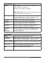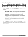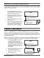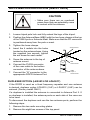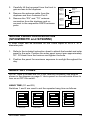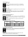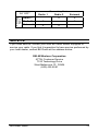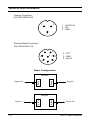
1
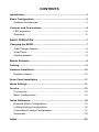
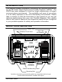
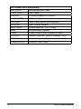
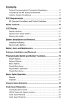
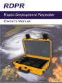
Contents
Introduction.........................................................................................3
Basic Configuration............................................................................3
Optional Accessories......................................................................4
Controls and Connections.................................................................5
LED Indicators.................................................................................6
Switches..........................................................................................6
BASIC OPERATION.............................................................................7
Charging the RDPR............................................................................7
Wall Charger Adaptor......................................................................8
Solar Panel . ...................................................................................8
Vehicle Adaptor...............................................................................8
Mobile Extender..................................................................................9
Linking.................................................................................................9
Antenna Installation.........................................................................10
Duplexer Option............................................................................10
Solar Panel Installation ................................................................... 11
Mode Settings................................................................................... 11
Service...............................................................................................13
Connectors....................................................................................14
Basic Configuration.......................................................................14
Quick Reference...............................................................................14
External Radio Configuration........................................................15
In-Band Linking Configuration......................................................16
Cross-Band Linking Configuration................................................17
Schematic.....................................................................................18
Notes..................................................................................................20
Introduction
This manual contains information concerning the operation procedures
for the BK Radio Rapid Deployment Portable Repeater (RDPR). The
RDPR has been designed to meet the tough requirements of today’s
communications environment. The portability and ease of use allows
it to be easily deployed in the most demanding environments. Please
take a moment to read the information in this manual so you can get
optimum performance from your new Portable Repeater. Also, please
refer to the Owner’s Manual of the respective radios that are configured
in your portable repeater for safety and operation information.
Basic Configuration
Radio Sets*
12V, 7 Ah,
SLA Battery
Weather Proof Case
Mounted
under panel
RADIO 2
RADIO 1
RF 2
INPUT
ER
W
RADIO
PORT 2
BK RADIO
PO
Y
ER
TT
BA
E
G
AR
AT
2
RE
RE
R
RADIO 2 PWR
2 ABC
AT
1
PE
PE
CH
RADIO
PORT 1
KNG
E
AT
PE
VOX / COR
1
Digital
RF 1
INPUT
RE
ER
W
PO
RADIO 2
ON
ON
MOBILE
EXTENDER
OFF
OFF
VOX / COR
RADIO 1 PWR
3 DEF
4 GHI
5 JKL
6 MNO
7PQRS
8 TUV
9WXYZ
*
0
#
BATTERY
1
2
3
4
5
6
7
8
9
ENT
*
0
#
CLR
FCN
PRI
CHARGER
Interface
Connector*
Radio Set Mounting Plate*
Mounting Nut
*Interface connectors, and mounting plates are dependant radio set type.
Contact RELM Wireless for availble radio types.
RELM/BK Radio
3
Optional Accessories
4
MECRDPR
Mobile Extender Cable
LINKCRDPR
Link Cable
VARDPR
Charging Adaptor for Vehicle
SP20WRDPR
20W Solar Panel
SP20WM
Solar Panel Mount and hardware.
WCRDPR
Wall Charger Adaptor
MWV1360S
Mobile Antenna, 136-174MHz
MBS
Antenna Base Adaptor
TAM8
Tripod (Solar Panel & Antenna Mount)
LZA3015
Internal Duplexer, Factory Installed (VHF)
LZA3017
Internal Duplexer, Factory Installed (UHF)
CABANTRDPR
Antenna Coax Cable
RDPR User’s Manual
Controls and Connections
DC/Charge Port
Data Port Radio 2
Data Port Radio 2
LED and Switch Array
See Detail A
RF Inputs
RADIO 2
RADIO 1
RF 2
INPUT
ER
W
PO
RADIO
PORT 2
BK RADIO
Y
ER
TT
BA
E
G
AR
AT
2
RE
AT
1
PE
PE
CH
RE
RADIO
PORT 1
KNG
R
RE
RADIO 2 PWR
2 ABC
E
AT
PE
VOX / COR
1
Digital
RF 1
INPUT
ER
W
PO
RADIO 2
ON
ON
MOBILE
EXTENDER
OFF
OFF
VOX / COR
RADIO 1 PWR
3 DEF
4 GHI
5 JKL
6 MNO
7PQRS
8 TUV
9WXYZ
*
0
#
BATTERY
1
2
3
4
5
6
7
8
9
ENT
*
0
#
CLR
FCN
PRI
CHARGER
Radio 2 Power
Radio 1 Power
SW6 Access
Moblie Extender/Link Port
Fuse Holders
Antenna Port 2/Duplexer Port
W
ER
PO
T
BA
RY
TE
E
RG
C
HA
EP
T
EA
R
2
T
EA
Power On
Battery Charged
Battery being charged
Repeater Function On
Repeater Function On
RELM/BK Radio
DETAIL A
DETAIL A
E
AT
PE
RE
VOX / COR
LED Indicators
LED Indicators
Power
Battery
Charge
Repeat 1
Repeat 2
R
1
EP
R
Antenna Port 1
ER
W
PO
RADIO 2
ON
ON
MOBILE
OFF
OFF
VOX / COR
Toggle Switches
Switches
VOX/COR
Voice or Carrier Activation
Radio 2/Mobile
Enable External Radio
Repeater On/Off Repeater Function
Power On/Off
RDPR Unit Power
5
LED Indicators
Power
With Detect On (Refer to the Mode Settings, page 11)
Solid - Ready for operation.
Blinking - Not ready for operation.
With Detect OFF (Refer to the Mode Settings, page 11)
Solid - Master Power switch is on.
Battery
Indicates battery is near depletion and in need of
charge. Depending on activity, the battery will last
approximately one hour after illumination.
Charge
Indicates the internal battery is charging,
Repeat 1
When lit, Radio 2 (left side) is repeating the
received signal from Radio 1 (right side).
Repeat 2
When lit, Radio 1 (right side) is repeating the
received signal from Radio 2 (left side).
Repeat 1
and
Repeat 2
When lit, Radio 1 and Radio 2 are repeating the
received signal from the radio connected to the
external radio port.
Switches
Power
Master switch to power-up the RDPR.
Repeater
Switches power to the “Radio 1 PWR” and “Radio 2
PWR” ports to enable/disable repeater function.
Radio 2/Mobile
Switches Radio 2 off when using the external radio
port.
VOX/COR
Switches between voice/noise activated (VOX) or
carrier activated (COR) repeat function.
SW6
Refer to the Mode Settings on page 11
6
RDPR User’s Manual
BASIC OPERATION
If needed, program the installed radio sets. The “Power”, “Repeater”,
and “Radio 2” switches should be on to supply power to the radio sets
being programmed.
See the specific radio’s programming manual for programming details.
1. Switch the “Power”, “Repeater”, and “Radio 2” switch to the “ON”
position.
2. Adjust the squelch on receiving radios for desired signal level.
3. Adjust the volume control knob of the receiving radio to the 10 o’clock
– 11 o’clock position. This will set the VOX sensitivity as well the
transmit deviation level. Do not set volume knob past the 12 o’clock
position. Use a service monitor or compatible transmitter and receiver
to test the repeat function.
Charging the RDPR
Warning
• Do not charge the RDPR if it is
exposed to temperatures less than
-20°C (4°F) or temperatures greater
than +50°C (+122°F).
• When the battery is not being
charged, make sure the master power
switch is in the “OFF” position.
NOTE: The Master Power Switch must be on during battery charging.
When the Battery LED is illuminated, the RDPR internal battery is in need
of charging.
When charging the RDPR, the internal charging circuit monitors the
battery voltage and detects a full charged condition. When the battery is
fully charged, the amber Battery LED and red Charge LED will not be lit.
When the battery reaches sufficient operating voltage, approximately 13
Volts, the Battery LED will turn off. The Charge LED remains lit until the
battery is fully charged.
RELM/BK Radio
7
Battery Condition Indicators
Charge
Needed
Battery
Charging
Charged to
Usable Level
Fully
Charged
Battery LED
ON
ON
OFF
OFF
Charge LED
OFF
ON
ON
OFF
The RDPR can be charged by connecting the RDPR to the DC wall
adaptor (WCRDPR), Solar Panel (SP20WRDPR), or Vehicle Adaptor
(VARDPR).
•
Wall Charger Adaptor - Connect the WCRDPR AC plug into the
AC source and connect the DC plug into the DC/Charge Port of
the RDPR. The WCRDPR is intended for indoor use only.
•
Solar Panel – Locate and position the panel so it gets the
maximum exposure to sunlight throughout the day. Connect the
DC plug into the DC/Charge Port of the RDPR.
•
Vehicle Adaptor – Connect the adaptor plug into the vehicle’s
DC accessory jack. Connect the DC plug into the DC/Charge
Port of the RDPR.
NOTE: To prolong the life of the internal battery, it is recommended to
store the RDPR with the battery fully charged. If the RDPR is not in
service and not being charged, make sure the master power switch is in
the “OFF” position.
8
RDPR User’s Manual
Mobile Extender (MECRDPR)
The Mobile Extender Cable (MECRDPR) allows the use a BK Radio
mobile as the transmitting unit to take advantage of the mobile radio’s
higher RF power output.
1. Connect the modular plug of
the MECRDPR into the mobile
radio’s microphone jack.
2. Connect the other end to the
Mobile Extender/Link Port of
the RDPR.
3. Switch the RDPR and mobile
radio power on.
4. If the primary transmitting radio
within the RDPR (Radio 2) is
not needed, set the “Radio 2”
switch to the “OFF” position.
RDPR
Mobile Extender/Link Port
MECRDPR
Radio
Power
Supply
Microphone Jack
Mobile Radio
Linking (LINKCRDPR)
The RDPR can be used for Linking using the LINKCRDPR cable with a BK
mobile or GBH/DBH base station, the RDPR can be used for Linking.
When a valid receive signal is received on the primary receiver (Radio 1),
the primary transmitter (Radio 2) and the mobile/base station will transmit
the received audio.
When a valid receive signal is received on the mobile/base station, the
primary transmitter (Radio 2) will be transmitting the received signal.
1. Connect the DB15 connector
of the MECRDPR into the
accessory port at the rear of
the mobile or base station and
connect the other end to the
Mobile Extender/Link Port of
the RDPR.
2. Switch the RDPR main power
and repeater power on.
3. Switch the mobile or base
station power on.
RDPR
Mobile Extender/Link Port
LINKCRDPR
Accessory Jack
Radio
Power
Supply
Mobile Radio
Refer to the Mode Settings (page 11) for linking options.
RELM/BK Radio
9
Antenna Installation (MWV1360S)
Caution
• Make sure there are no overhead
power lines that can potentially come
in contact with the antenna.
1. Loosen tripod pole lock and fully extend the legs of the tripod.
2. Position the Antenna Base (MBS) with the two hose clamps at the top
of the TAM 8 pole or Antenna Mast. Make sure that the RF connector
is positioned away from the pole or mast.
3. Tighten the hose clamps.
Antenna Mount
4. Insert the 4 radials into the holes
located on the antenna base. Using
the supplied hex wrench, tighten
the set screw for each radial.
5. Screw the antenna to the top of
antenna mount.
MBS
Antenna Base
6. Connect the PL259 connector
of the coax cable to the bottom
connector of the antenna base.
TAM8
Tripod or
Antenna Mast
7. Connect the “N” connector to the
approproate RDPR Antenna Port.
Duplexer Option (LZA3015 or LZA3017)
If the RDPR is used as a fixed frequency repeater and one antenna
is desired, duplexer option LZA3015 (VHF) or LZA3017 (UHF) can be
ordered. (Factory install ONLY.)
If a duplexer is installed the antenna is connected to Antenna Port 2. If
no duplexer is installed, the antenna ports on each side of the case are
to be used.
To disconnect the duplexer and use the two antenna ports, perform the
following steps:
1. Remove the two radio mounting plates.
2. Remove the eight hex screws of the top panel.
10
RDPR User’s Manual
3. Carefully tilt the top panel from the front to
gain access to the duplexer.
4. Remove the antenna cable from the
duplexer and from Antenna Port 2.
RDPR
Antenna
Port 1
Duplexer
Setup
Non-Duplexer
Setup
Radio 1
Antenna
5. Remove the “RX” and “TX” antenna
connection from the duplexer and reconnect to the respective RDPR antenna
ports.
Receiver
RDPR
Antenna
Port 2
Antenna
Transmitter
Radio 2
Antenna
Solar Panel Installation
(SP20WRDPR and SP20WM)
A Solar Panel can be mounted on the TAM8 tripod or on a 2’ to 3”
diameter pole.
1. Refer to the included instruction sheet to attach the bracket and solar
panel to the pole. Position the solar panel mount arm approximately
20°- 30°down from the horizon and tighten the bolts.
2. Position the panel for maximum exposure to sunlight throughout the
day.
Mode Settings
NOTE: Note to access the DIP SW6, remove the plastic cap plug as
shown in the diagram on page 5. Use a pencil or a small screw driver to
turn on or OFF the switch.
Hang Time (S1 and s2)
Switches 1 and 2 are used to set the repeater hang time as follows:
1
OFF
ON
1
OFF
ON
1
OFF
ON
1
2
2
2
2
3
3
3
3
4
4
SW6
0 Seconds
RELM/BK Radio
4
SW6
1 Seconds
OFF
ON
4
SW6
2 Seconds
SW6
3 Seconds
11
Radio Detect (S3)
1
OFF
S3 - “ON”.
ON
If any or all of the radios are turned off or not plugged in
the power LED will flash and the repeater function will be
inoperable.
2
3
4
SW6
1
OFF
S3 - “OFF”.
ON
The repeater function is operable even if one of the radios is
off or unplugged.
2
3
NOTE: This setting is used when only one of the RDPR
internal Radio Sets is being used in conjunction with an
external radio.
4
SW6
Linking Configurations (S4)
In-Band Linked Repeater
OFF ON
When an external radio is attached via the LINKCRDPR link
1
cable it will transmit whenever Radio 1 or Radio 2 receives a
2
signal.
3
Radio 2 transmits whenever a signal is received by the
external radio.
4
SW6
Radio 1 acts as receive only.
Receiving
Radio
S4 “ON”.
Transmitting Radio
Radio 1
Radio 1
Radio 2
External
X
X
Radio 2
External
X
X
Cross-Band Linked Repeater
1
OFF
ON
2
3
When an external radio is attached via the LINKCRDPR link
cable, whenever a signal is received by one radio set, the
other two sets will transmit.
4
SW6
NOTE: When using this option the hang time must be set to zero
seconds. (Refer to Hang Time Settings, page 11)
12
RDPR User’s Manual
Transmitting Radio
Receiving
Radio
S4 “OFF”.
Radio 1
Radio 1
Radio 2
X
External
X
Radio 2
External
X
X
X
X
Service
If you need service, contact your local BK Radio dealer equipped to
service your radio. If you find it impractical to have service performed by
your local dealer, contact BK Radio at the address below:
RELM Wireless Corporation
ATTN: Customer Service
7100 Technology Drive
West Melbourne, FL 32904
(800) 422-6281
RELM/BK Radio
13
Quick Reference
Charger Connector
PN 2105-20035-708
1
3
1 - 18VDC IN
2 - NC
3 - GND
2
External Radio Connector
PN 2105-20035-710
1
7
8
2
3
6
2 - PTT
3 - GND
4 - Mic Hi
5
4
Basic Configuration
Radio 1
Signal In
Radio 1
Signal Out
Radio 2
RDPR
Signal Out
Signal In
14
Radio 2
RDPR
RDPR User’s Manual
External Radio Configuration
With Radio 2 Switch ON
Signal Out
Radio 1
Signal Out
Radio 2
RDPR
External Radio
Signal In
External Radio
Power Supply
Signal Out
Radio 1
Signal In
Radio 2
RDPR
Signal Out
External Radio
Power Supply
External Radio
With Radio 2 Switch OFF
Signal Out
RELM/BK Radio
External Radio
Radio 1
Radio 2
RDPR
Signal In
External Radio
Power Supply
15
In-Band Linking Configuration
S4 On
Signal Out
Radio 1
Signal Out
Radio 2
RDPR
Signal In
External Radio
Power Supply
External Radio
Signal Out
Radio 1
Signal In
Radio 2
RDPR
External Radio
External Radio
Power Supply
Signal In
16
External Radio
Radio 1
Signal Out
Radio 2
RDPR
External Radio
Power Supply
RDPR User’s Manual
Cross-Band Linking Configuration
S4 Off
Signal Out
Radio 1
Signal Out
Radio 2
RDPR
Signal In
External Radio
Power Supply
External Radio
Signal Out
Radio 1
Signal In
Radio 2
RDPR
External Radio
Signal Out
External Radio
Power Supply
Signal In
RELM/BK Radio
External Radio
Radio 1
Signal Out
Radio 2
RDPR
Signal Out
External Radio
Power Supply
17
3333-30965-200ver D.
18
RDPR User’s Manual
RELM/BK Radio
19
Notes
20
RDPR User’s Manual