1
US 20010007140A1
(19) United States
(12) Patent Application Publication (10) Pub. No.: US 2001/0007140 A1
(43) Pub. Date:
Landry et al.
(54) OPERATING SYSTEM-INDEPENDENT
COMPUTING SYSTEM USER FEEDBACK
MECHANISM
(76) Inventors: John A. Landry, Spring, TX (US);
Valiuddin Y. Ali, Houston, TX (US);
Ajay Chaturvedi, Baltimore, MD (US);
Jul. 5, 2001
Related US. Application Data
(63)
Continuation of application No. 09/478,153, ?led on
Jan. 5, 2000.
Publication Classi?cation
(51)
Int. Cl? ................................................... .. G06F 11/00
(52)
US. Cl. .............................................................. .. 714/48
Brooks A. Rorke, Satellite Beach, FL
(US); Stacy L. Wol?', Cypress, TX
(57)
(US); Kevin L. Massaro, Houston, TX
A computing system employs a user feedback mechanism to
ABSTRACT
monitor operating conditions of the computing system and
(Us)
to alert a user to the operating conditions independently of
Correspondence Address:
AKIN, GUMP, STRAUSS, HAUER & FELD
an operating system of the computing system. The user
feedback mechanism includes a display panel to display
operating condition messages to the user and includes a
711 LOUISIANA STREET
SUITE 1900 SOUTH
controller to monitor operating condition signals. Some
examples of operating conditions include a connection state
HOUSTON, TX 77002 (US)
of the computing system to the Internet, a connection state
of a peripheral device to the computing system, a neW e-mail
noti?cation message, a neW Internet message and atomic
(21) Appl. No.:
09/771,866
time from a netWork server coupled to the computing
system. The user feedback mechanism may include a safety
button to signal a poWer supply to poWer off the computing
(22) Filed:
Jan. 29, 2001
system independently of the operating system.
Patent Application Publication
Jul. 5, 2001
Sheet 1 0f 7
US 2001/0007140 A1
/ CS
COMPUTING SYSTEM snETwARE
/ 100
SYSTEM
/ 126
REGISTRY
I
OPERATING SYSTEM
124
120
r
122
INTERNET
TASK
MANAGER
SCHEDULER
BLOCK
/ 110
as INTEREAcE
f 102
:
SYSTEM
BIDS
BIOS
INTEREAcE
706 \
_/ 112
118
"""""""""""""""""""" '
\
ACPI
INTERFACE
LCD INTEREAcE
DRIVER
\
5
\ 114
FIG. 1
Patent Application Publication
Jul. 5, 2001
Sheet 2 0f 7
US 2001/0007140 A1
/ CH
COMPUTING SYSTEM HARDWARE
/ 200
[IS-INDEPENDENT usER FEEDBACK MECHANISM
MIM LCD
/ 204
I
/- 202
INTERFACE
CONTROLLER
/ 208
SAFETY
BUTTON
MESSAGE
INDICATOR
A
f 210
AcPI
LOG";
f 216
AcPI
TIMER
f 220
MONITOR
/2
12
222
/
KEYBOARD
MAIN
PROCESSOR
224
f 214
223
\
MuusE
PnwER
SUPPLY
FIG. 2
f
PERIPHERAL
DEVICE
Patent Application Publication
Jul. 5, 2001
Sheet 3 0f 7
US 2001/0007140 A1
Os-INOEPENOENT
OPERATING
GONOITION FEEDBACK
PROcEss
317
\
_>
APPUBATIUN
SEND
OPERATING
GONOITION
, /302 306\ ,
+f31O
# [314 31a\ ‘
DETECT
GONNEGTION
sTATE
GONNEGTION
STATE
304\ V
OETEGT
OETEGT
LOCUKST UP
308\ ‘
{312
[316
OETEGT
KEDIFQEKED
PERIPHERAL
OETEGT
DETECT
GONNEGTION
STATE
DEV'GE
GONNEGTION
STATE
EMAIL
NOTIFICATION
ATOMIO
TIME
I
l
V
328 \
I
II
J:
v
f 320
US DR
COMMUNICATE
APPLICATION
REAO
0F OPERATING
OPERATING GONOITION
TO MINI LCD
GONOITION
/- 324
DISPLAY OPERATING
CONDITION MESSAGE
,
f 325
GENERATE OPERATING
GONOITION DISPLAY
COMPLETE SIGNAL
l
/ 326
DISPLAY INSTRUCTION
TO cuRE OPERATING
GONOITION
FIG. 3A
Patent Application Publication
Jul. 5, 2001
Sheet 4 0f 7
CLEAR INSTRUCTION
FROM MINI LCD
334
INTERNET
MESSAGE OR
E-MAIL
NOTIFICATION
DETECTED
'7
336
SET MESSAGE
INDICATOR
UPDATE USER
INTERFACE
MECHANISM CLOCK
AND OS CLOCK
OPERATING
CONDITION FEEDBACK
PROCESS COMPLETE
FIG. 38
US 2001/0007140 A1
Patent Application Publication
Jul. 5, 2001
Sheet 5 0f 7
SAFETY BUTTON
PROCESSING
402
START ACPI
TIMER
+
f 404
INITIATE
SHUTDOWN
OF OS
ACPI TIMER
EXP'IIRED
OS
SHUTDOWN
?
/-410
RESET ACPI
LOGIC SIGNALING
POWER SUPPLY
TO TURN OFF
SAFETY BUTTON
PROCESSING
COMPLETE
FIG. 4
US 2001/0007140 A1
Patent Application Publication
Jul. 5, 2001
Sheet 7 0f 7
US 2001/0007140 A1
100
OPERATING SYSTEM
/ 602
/ 604
APPLICATION
APPLICATION
/ 600
LCDCOM-B
INTEARSACE
ED
/ 612
L
I
I
CLIENT
/ 118
LCD INTERFACE
DRIVER
102
SYSTEM BIOS
608
IIO LOGIC
ACPI
.
LOGIC
mm
X 210
214
\ 606
f 202
f 204
MINI LCD
POWER SUPPLY
INTERFACE CONTROLLER
UART
610 '
FIG. 6
Jul. 5, 2001
US 2001/0007140 A1
OPERATING SYSTEM-INDEPENDENT
COMPUTING SYSTEM USER FEEDBACK
MECHANISM
detecting When a computer system is in fact connected to the
Internet. In the case of a user Who frequently moves his or
her desktop computer, such a user may be forced to check
one or more cable connections if the computer does not
CROSS-REFERENCE TO RELATED
APPLICATIONS
[0001] This application is a continuation-in-part of US.
patent application Ser. No. 09/478,153, entitled “DIGITAL
FEEDBACK DISPLAY PANEL AND SUPPORTING
SOFTWARE FOR A COMPUTER USER,” ?led Jan. 5,
2000, Which is incorporated herein by reference in its
entirety for all purposes.
BACKGROUND OF THE INVENTION
[0002]
1. Field of the Invention
[0003] The present invention generally relates to operating
condition user feedback for computing systems, and more
particularly to an operating system-independent user feed
back mechanism of a computing system.
poWer-up after the computer is relocated. Users thus are
typically not Well informed of the operating conditions or
events of computer systems, if at all, and must resort to
contacting the computer manufacturer, contacting the Inter
net service provider, examining the user’s manual or exam
ining the computer itself When a perceived problem devel
ops.
SUMMARY OF THE INVENTION
[0008] Brie?y, a computing system employs a user feed
back mechanism to monitor a plurality of operating condi
tions of the computing system and to alert a user to the
plurality of operating conditions independently of an oper
ating system of the computing system. The user feedback
mechanism includes a display panel to display a plurality of
operating condition messages to the user and includes a
[0004] 2. Description of the Related Art
controller to monitor a plurality of operating condition
signals. Further, the user feedback mechanism is indepen
[0005]
dently poWered and further includes a safety button to signal
User feedback With respect to operating conditions
or states of a computer system has typically been provided
a poWer supply to poWer off the computing system inde
by a monitor, audio alerts, light emitting diodes (LEDs) or
directly by an operating system of the computer system.
pendently of the operating system. Examples of operating
Each of these forms of user feedback in effect depends upon
conditions include a connection state of the computing
system to the Internet and a connection state of a peripheral
operating system control. Where an operating condition
device to the computing system. Other examples of operat
relates to an error With the operating system itself, the
operating system cannot detect such an error. A lock-up of
ing conditions that the user feedback mechanism displays to
the user independently of the operating system include a
the operating system is therefore particularly dif?cult for a
user to detect. One draWback of relying upon the operating
system and the monitor to provide user feedback is that
neither the operating system nor the monitor are available at
neW e-mail noti?cation message, a neW Internet message or
atomic time from a netWork server coupled to the computing
system. An operating condition message is cleared from the
display panel When the operating condition is cured.
all times. Acomputer system is typically con?gured to enter
a loW poWer or sleep mode after a certain period of idle time
Where neither the monitor nor the operating system are
BRIEF DESCRIPTION OF THE DRAWINGS
available. Because of the unavailability of the monitor and
the operating system in a loW poWer mode, certain operating
[0009] Abetter understanding of the present invention can
be obtained When the folloWing detailed description of the
preferred embodiment is considered in conjunction With the
conditions are not communicated to a user. For example, a
user cannot determine When a neW e-mail is available during
a loW poWer mode. Even a feature such as a digital clock has
depended upon the monitor being fully aWake and upon the
operating system.
[0006]
Many computer users tend to be frustrated With
user feedback in the form of audio alerts and LEDs. Audio
alerts are perceived by users as annoying. Many users
therefore loWer the volume of their computer systems,
defeating the purpose of the audio alerts. LEDs (including
the hard disk drive LED of a computer system) are perceived
by users as confusing, particularly Where ?ashing patterns of
the LEDs signify different operating conditions of the com
puter system. Even When users someWhat understand an
operating condition conveyed by the monitor, audio alerts or
LEDs, most users are fearful of touching and inadvertently
“crashing” or depoWering their computer systems, thereby
risking a loss of data.
[0007] The operating system, monitor, audio alerts and
LEDs alike have provided little, if any, feedback to users
during critical times for a computer system such as system
initialiZation or poWer-up, for example. Users tend to ignore
or overlook any system information Which is quickly ?ashed
on the monitor during poWer-up. Users also have dif?culty
folloWing draWings, in Which:
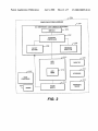
[0010]
FIG. 1 is a block diagram of an exemplary soft
Ware architecture of a computing system With an operating
system-independent user feedback module;
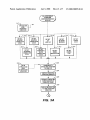
[0011] FIG. 2 is a block diagram of an exemplary hard
Ware architecture of the computing system With an operating
system-independent user feedback mechanism;
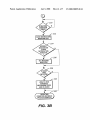
[0012]
FIGS. 3A and 3B shoW a ?oW chart illustrating
exemplary operation of the operating system-independent
user feedback module of FIG. 1 and the operating system
independent user feedback mechanism of FIG. 2;
[0013]
FIG. 4 is a ?oW chart illustrating exemplary pro
cessing of the safety button of the operating system-inde
pendent user feedback mechanism of FIG. 2;
[0014] FIG. 5 is a block diagram of an exemplary archi
tecture of the operating system-independent user feedback
module of FIG. 1; and
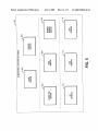
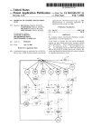
[0015] FIG. 6 is a block diagram illustrating exemplary
application-level interfacing and system-level interfacing
for the operating system-independent user feedback mecha
nism of FIG. 2.
US 2001/0007140 A1
DETAILED DESCRIPTION OF PREFERRED
EMBODIMENT
[0016] The following commonly-assigned patent applica
Jul. 5, 2001
display instructions to a user for the user to cure the
particular operating condition. It should be understood that
the mini display 204 may be implemented With display
technologies other than LCD. The message indicator 208,
tion is incorporated herein by reference in its entirety for all
Which for eXample may be implemented as one or more
purposes:
light-emitting diodes (LEDs), is used to indicate messages to
[0017] US. patent application, Ser. No. 09/557,700,
entitled “OPERATING SYSTEM HANG DETECTION
AND CORRECTION,” ?led Apr. 25, 2000 by Craig L.
Chaiken and Stan Stanart.
a user such as an email message or an Internet message. The
term “Internet message” refers to any non-email message
communicated over the Internet, such as messages unique to
a particular Internet service provider. The safety button 206
is used to signal a poWer supply 214 to poWer off the
[0018]
Turning noW to the drawings, FIG. 1 shoWs eXem
plary computing system softWare CS including an operating
system 100, system BIOS (Basic Input Output System) 102,
computing system if the computing system is not already
poWered off by the operating system 100. Processing of the
an operating system-independent user feedback or interface
safety button 206 is described in more detail beloW in
connection With FIG. 4.
module 106 and an LCD (liquid crystal display) interface
driver 118. The operating system 100 is a typical operating
system including a system registry 126, a clock 120, an
[0020] The interface controller 202 is further coupled to
ACPI logic 210. The ACPI logic 210, Which is shoWn
including an ACPI timer 212, is coupled to the poWer supply
Internet manager 124 and a task scheduler 122. The oper
ating system 100 is coupled to both system BIOS 102 and
the user feedback module 106. The user feedback module
106 includes an operating system interface 110 coupled to
the operating system 100, a BIOS interface 112 coupled to
the system BIOS 102 and an ACPI (Advanced Con?guration
and PoWer Interface) interface 114 to interface With ACPI
logic. The LCD interface driver 118 is also coupled to the
user feedback module 106. The user feedback module 106,
the LCD interface driver 118 and the system BIOS 102 in
combination provide softWare control of an operating sys
tem-independent user feedback or digital dashboard mecha
nism 200 such as shoWn in FIG. 2. The term “computing
system” as used herein refers to any system With a superset
or subset of processing or Internet functions of a computer
214. The use of the ACPI timer 212 is described beloW in
connection With FIG. 4. The arroWed line from the poWer
supply 214 to the user feedback mechanism 200 represents
that the user feedback mechanism 200 is poWered indepen
dently of the rest of the computing system. When the user
feedback mechanism 200 is poWered (i.e., When the user
feedback mechanism poWer cable is plugged in), the mini
LCD 204 is lit. Unlike the computing system itself, the user
feedback mechanism 200 is preferably left on or poWered at
all times. The user feedback mechanism 200 thus operates
even When the computing system is off or asleep. Other
illustrated hardWare of the computing system includes a
main processor 216, a monitor 220, a keyboard 222, a mouse
223 and a peripheral device 224. The main processor 216 is
information appliances.
a typical microprocessor for running an operating system
and other softWare. The monitor 220, the keyboard 222, the
mouse 223 and the peripheral device 224 represent periph
[0019] Referring to FIG. 2, exemplary computing system
eral devices Which may generate operating conditions to be
system, including but not limited to Internet appliances and
hardWare CH including the user feedback mechanism 200 is
shoWn. The user feedback mechanism 200 is employed to
monitor operating conditions (including fault conditions) of
a computing system and to alert a user to the operating
conditions independently of the operating system 100. The
concept of “monitoring” operating conditions should be
construed to encompass detecting data and processing the
data to a more meaningful form to determine an operating
condition. An operating condition generally refers to any
event or condition related to the operation of the computing
system, including but not limited to fault conditions of the
computing system. The term “fault condition” should be
detected and then displayed to a user. For eXample, if the
monitor 220 is disconnected, a message (e.g., teXt and/or
icon) indicating the monitor 220 is disconnected may be
displayed on the mini LCD 204. In a disclosed embodiment,
the user feedback mechanism 200 monitors each level of
connection and removal of peripheral devices of the com
puting system. The monitor 220, the keyboard 222 and the
mouse 223 are treated as primary devices of the computing
system. As such, the states of these devices are checked
during system initialiZation as described in more detail
beloW.
construed to encompass any system condition that may
[0021] Referring to FIGS. 3A-3B, an eXemplary operating
system-independent operating condition feedback process
negatively impact a user’s experience With the computing
system. The operating system-independent user feedback
using the user feedback mechanism 200 is shoWn. The
process begins at any of the steps 302-318 Which represent
mechanism 200 includes a mini display or LCD 204, an
interface controller 202, a message indicator 208, and a
the operating condition is an Internet connection state of the
safety button 206. The interface controller 202 is shoWn
coupled to the mini LCD 204, the message indicator 208,
and the safety button 206. A user is alerted of operating
conditions of the computing system by the mini LCD 204
displaying operating condition messages. The mini LCD
204 receives an operating condition signal from the interface
controller 202 and then displays a corresponding operating
condition message. A variety of operating condition signals
and operating condition messages may be supported by the
detection of a variety of operating conditions. In step 302,
computing system. In step 304, the operating condition is the
keyboard connection state of the computing system. In step
306, the operating condition is the monitor connection state
of the computing system. In step 308, the operating condi
tion is the connection state of a peripheral device in the
computing system. In step 310, the operating condition is a
lock-up of the operating system 100. In step 312, the
operating condition is an email noti?cation. In step 314, the
operating condition is an Internet message. In step 316, the
user feedback mechanism 200. In addition to displaying
operating condition is the atomic time. The computing
operating condition messages, the mini LCD 204 may also
system may detect atomic time from a netWork server during
US 2001/0007140 A1
Jul. 5, 2001
an Internet connection. In a disclosed embodiment, a default
mode of the user feedback mechanism 200 is a clock mode
operating conditions. If an Internet message or an email
in Which atomic time is displayed on the mini LCD 204.
336 Where the message indicator 208 is set. For example, if
tWo email noti?cations Were detected, then the message
indicator 208 is set to periodically blink tWice. If an Internet
message or email noti?cation is not detected in step 334,
Compared to a typical operating system-based clock of a
computer system, the clock mode of the user feedback
mechanism 200 runs independently of the operating system
noti?cation is detected in step 334, control proceeds to step
100 and provides a more accurate clock. Even if a user does
then control proceeds directly to step 338. In step 338, it is
not initiate connection to the Internet every day, the user
feedback mechanism 200 automatically connects to the
Internet each day to ensure the accuracy of its clock. This
determined if atomic time is detected. If not, control pro
automatic Internet connection feature may be con?gured by
a user to force an Internet connection as many times a day
as desired and at Whatever times are desired. Since an
OS-based clock is at times not visible on a monitor, users
have typically relied upon clocks external to their computer
systems. A user, hoWever, can vieW the clock of the user
feedback mechanism 200 at any time. In step 318, the
operating condition is the poWer state (i.e., sleep mode) of
the computing system. It should be understood that the
operating conditions shoWn in steps 302-318 are illustrative
and not exhaustive. As one example, an operating condition
Which may be detected using a Watermark setting is Whether
a hard disk drive of the computing system is almost full. As
another example, it may be detected Whether the hard disk
is about to crash. An operating condition may be detected by
a noti?cation or alert. Alternatively, at a desired time, the
process may poll or query for an operating condition. For
each of steps 302-318, control proceeds next to step 320. In
step 320, the operating condition is communicated to the
mini LCD 204. Communication of an operating condition to
the mini LCD 204 is described beloW in connection With
ceeds to step 342 indicating the operating condition feed
back process is complete. If atomic time is detected in step
338, then control proceeds to step 340 Where the clock 120
of the operating system 100 and a clock of the user feedback
mechanism 200 are both updated With the atomic time. By
updating the clock of the user feedback mechanism 200, the
mini LCD 204 displays atomic time. From step 340, the
process is completed in step 342.
[0024] Referring to FIG. 4, processing of the safety button
206 (FIG. 2) is shoWn. The process begins in step 400 Where
it is determined if a press or actuation of the safety button
206 by a user is detected. If a press or actuation is not
detected, then control remains in step 400. If a press or
actuation is detected, then control proceeds to step 402
Where the ACPI timer 212 is started. Next, in step 404 a
shutdoWn of the operating system 100 is initiated. Control
then proceeds to step 406 Where it is determined if the ACPI
timer 212 has expired. If the ACPI timer 212 has not expired,
then control remains in step 406. If the ACPI timer 212 has
expired, then control proceeds to step 408 Where it is
determined if the operating system 100 is shutdoWn. Detec
tion of a hang up by the operating system 100 is described
in a commonly-assigned US. patent application, entitled
“OPERATING SYSTEM HANG DETECTION AND COR
FIG. 6. As represented by the step 328, a detected operating
RECTION,” previously incorporated herein. If the operating
condition may be read by an application or the operating
system 100 is shutdoWn, then control proceeds to step 412
Where processing of the safety button 206 is complete. If the
operating system 100 is not shutdoWn, then control proceeds
to step 412 Where the ACPI logic 210 is reset signaling the
poWer supply 214 to turn off. At this point, the computing
system 100.
[0022]
Next, control proceeds to step 324 Where an oper
ating condition message corresponding to the operating
condition is displayed by the mini LCD 204. From step 324,
control proceeds to step 325 Where an operating condition
display complete signal is generated by the interface con
troller 202. Control next proceeds to step 326 Where an
instruction to cure the operating condition is displayed by
the mini LCD 204. Next, in step 330, it is then determined
if the operating condition is cured. If the operating condition
is not cured, then control remains in step 330. In this Way,
the instruction to cure the operating condition remains
displayed until the operating condition is cured by the user.
If it is determined in step 330 that the operating condition is
cured, then control proceeds to step 332 Where the instruc
tion is cleared from the mini LCD 204. It should be
understood that step 326 of displaying an instruction to cure
system can be considered as in a “safe mode.” From step
410, control proceeds to step 412 Where the processing of
the safety button 206 is complete. This process provides a
Way to ensure that the operating system 100 is shutdoWn. By
using the safety button 206, a user can be ensured that the
computing system is in a depoWered state. With this assur
ance, a user can then be more comfortable opening or
moving the computing system. The use of the safe mode can
prevent a user from accidentally poWering off the computing
system With ?les open in the operating system 100.
[0025] Referring to FIG. 5, exemplary softWare compo
nents Which may be included in the user feedback module
106 of FIG. 1 is shoWn. As previously shoWn in FIG. 1, the
cases Where once a user is informed of the operating
user feedback module 106 includes an operating system
interface 110, the BIOS interface 112 and the ACPI interface
114. The user feedback module 106 may further include
client softWare components such as a device monitor 500, an
Internet monitor 502, an atomic time monitor 504, an email
monitor 506 and an Internet message monitor 508. The
device monitor 500 is used to detect the connection or other
condition, it is self-explanatory hoW to cure the operating
condition.
device is a CD-ROM drive, it can be detected Whether the
a operating condition is optional. For example, if the oper
ating condition message itself implies What a user needs to
do to cure an operating condition, it may be desirable to not
display an instruction to inform the user hoW to cure the
operating condition. In other Words, there may be some
state of peripheral devices. For example, if the peripheral
drive contains an audio CD, a data CD, or a DVD CD. In a
[0023] Steps 334-340 are presented to illustrate situations
Where steps in addition to message display are performed by
WM_DEVICECHANGE signal provided by the operating
the user feedback mechanism 200 after detecting certain
system 100 to detect device states. If the device is a printer,
disclosed embodiment, the device monitor 500 uses the
Jul. 5, 2001
US 2001/0007140 A1
then the device monitor 500 uses the WM_SPOOLERSTA
LCD 204. The application 602 or 604 can be written in any
TUS signal provided by the operating system 100 to detect
computer language (e.g., Java, C++ or HTML).
if a print job is started or ?nished. Those skilled in the art are
familiar with calling application programming interfaces
(APIs) into an operating system to retrieve desired informa
tion known by the operating system. A variety of standard
APIs may be employed to retrieve potentially useful infor
[0028]
The table below shows a variety of interface meth
ods for the LCD interface 600. Beside the name of each
interface method shown, a general description of the inter
face method is provided.
mation for a user from an operating system. In the past, such
information has not been retrieved, processed and displayed
to the user.
Interface Method Name
Interface Method Description
SetClock
This method updates the time of the internal
clock of the mini LCD and the system clock
SetClockEX
This method updates the date and time of the
internal clock of the mini LCD and the
SetLEDState
connection is made or disconnected. The atomic time moni
This method is used to set an LED for the
feedback mechanism to an on, off or blinking
tor 504 is used to detect atomic time from a server or
state. The supported LEDs are a sleep LED,
[0026] The Internet monitor 502 is used to detect if the
computing system is connected to the Internet. In a disclosed
embodiment, the Internet monitor 502 registers with the
operating system 100 to receive messages regarding Remote
Access Services (RAS). The Internet monitor 502 is
informed by a noti?cation or message when an Internet
of the operating system.
system clock of the operating system.
an Internet detect LED, a power LED, a
network computer coupled to the computing system during
an Internet connection. The email monitor 506 is used to
detect email noti?cations for the computing system. The
DisplayText
message LED and a backlight LED.
This method is used to control parameters for
displaying text on the mini LCD.
This method is used to display text on the
mini LCD with default text display
Internet message monitor 508 is used to detect Internet
SimplyDisplayText
messages for the computing system. The monitors 500-508
correspond to steps 302-308 and 312-316 of FIG. 3A. The
SimplyScrollText
This method is used to scroll text on the mini
GetLCDLongProperties
LCD with default scrolling parameters.
This method is used to fetch the properties of
parameters.
monitors 500-506 are described in more detail in the com
monly-assigned US. patent application, entitled “DIGITAL
FEEDBACK DISPLAY PANEL AND SUPPORTING
SOFTWARE FOR A COMPUTER USER,” previously
the mini LCD.
This method clears the text display area of the
mini LCD and displays the clock if no
ClearText
incorporated herein.
pending text is waiting to be displayed.
[0027] Referring to FIG. 6, exemplary application-level
DisplayIcon
interfacing and system-level interfacing for the user feed
back mechanism 200 is shown. Application-level interfacing
This method is used to control parameters for
displaying icons on the mini LCD.
SimplyDisplayIcon
This method is used to display icons on the
relates to an application 602 or 604 communicating with the
mini LCD 204. System-level interfacing relates to a client
612 communicating with the mini LCD 204. An LCD
mini LCD with default icon display
parameters.
BlinkIcon
This method is used to control blinking of
DisplayIconEX
This method is used to display icons on the
mini LCD with blinking and timeout control.
application 604 and an LCD interface driver 118. In a
ClearIcon
disclosed embodiment, communication to the mini LCD 204
LoadIcon
This method is used to clear an icon from the
mini LCD.
This method downloads an icon with its icon
handle to the mini LCD.
This method downloads an icon from a
icons on the mini LCD.
interface 600 is shown coupled to the application 602, the
in the form of system-level interfacing overrides communi
cation to the mini LCD 204 in the form of application-level
interfacing. The application 602 or 604 may for example be
a debug application to track the operating conditions
detected by the user feedback mechanism 200. In a disclosed
LoadIconFromBitmap
bitmap to the mini LCD.
LoadIconFromByteArray This method downloads an icon from a one
dimensional array to the mini LCD.
LoadIconFromPicture
This method extracts icon data from an OLE
embodiment, the LCD interface 600 is a component object
model (COM)-based interface called by the application 602
or 604 for communication with the mini LCD 204. The
techniques for a COM interface to communicate with an
application are well known in the art. COM is a well known
paradigm for interaction among software components. The
LCD interface 600 is used to provide the applications 602
and 604 an application-level logical interface to the mini
LCD 204 of the user feedback mechanism 200. For example,
the application 604 through the LCD interface 600 can
provide operating conditions to the user feedback mecha
nism 200 and can also specially con?gure display by the
mini LCD 204 for the particular application 604. The LCD
interface 600 is specially con?gured to encapsulate func
tionality for the application 602 or 604 to communicate with
the mini LCD 204 of the user feedback mechanism 200. The
LCD interface 600 is basically an open mechanism for any
application 602 or 604 known by or registered with the
operating system 100 to communicate with the mini LCD
204. The LCD interface 600 may also be used by the
application 602 or 604 to read information from the mini
picture object for the mini LCD.
LoadFont
This method extracts font data from an OLE
LoadFontFrom
This method downloads a font from a byte
font object for the mini LCD.
ByteArray
array to the mini LCD.
PlaySound
This method plays sound for the feedback
mechanism with default sound parameters.
This method controls parameters for playing
PlaySoundEX
sound for the feedback mechanism.
[0029]
It should be understood that the COM interface
methods disclosed herein are illustrative and not exhaustive.
[0030] Avariety of application-speci?c messages may be
displayed by the mini LCD 204. If the application for
example is Microsoft Word®, then the mini LCD 204 may
be used to indicate that Microsoft Word® is launching or to
indicate that Microsoft Word® is terminating. The applica
tion 602 or 604 can be scheduled for launching by the
operating system 100 and can be self-terminated when not
needed. As another example, if the application 604 is a
paging application, then the application 604 can signal the
Jul. 5, 2001
US 2001/0007140 A1
mini LCD 204 to display “paging mom” When the applica
description of FIG. 6, applications and clients are used
tion 604 is being used to page the mother of the user. Five
herein interchangeably. The client 612, such as one repre
other examples of applications that may communicate With
sented by any of monitors 500-508 in FIG. 6, communicates
With the mini LCD 204 through the LCD interface driver 118
or the system BIOS 102. The LCD interface driver 118 is
coupled to the LCD interface 600 and to input/output (I/O)
logic 608. In a disclosed embodiment, the LCD interface
the user feedback mechanism 200 include a calculator
application, a calendar application, an alarm application, a
voice mail application, and a Web-based diagnostic appli
cation for the computing system manufacturer to remotely
reply to service requests from the user or remotely doWnload
code updates to the user. Unlike application 604, application
602 is shoWn coupled to the operating system 100 to
represent that an application may leverage the resources of
the operating system 100. An application may also leverage
the resources of another application. It should be understood
that a variety of applications or clients may communicate
With the user feedback mechanism 200. As such, the appli
cations and clients disclosed herein are illustrative and not
exhaustive. With the exception of reference numerals in the
driver 118 is con?gured as an RS-232 or other serial port
driver. In addition, in a disclosed embodiment, the driver 118
includes entry points typical of a WindoWs driver model
(WDM)/NT driver as Well as driver entry points specialiZed
for the user feedback mechanism 200. The table beloW
shoWs a variety of driver entry points used in connection
With the user feedback mechanism 200. Beside the name of
each driver entry point shoWn, a description of the driver
entry point is provided.
Driver Entry Point Name
CPQLCDiDriverEntry
Driver Entry Point Description
This routine ensures that the driver is loaded
When the mini LCD is found. It also registers
the rest of the entry points of the driver With
the operating system and makes them visible
to the operating system.
CPQLCDiDispatch
This routine services the calls from
applications/clients and services IOCT Ls
CPQLCDiStartIo
This routine is used to interface With a
CPQLCDiUnload
physical device.
This routine disconnects and un-registers
CPQLCDiAddDevice
This routine adds a device object When a neW
CPQLCDiRemoveDevice
CPQLCDiCreate
This routine removes a device.
Which are supported by the driver.
from all the interrupts that it services once it
has unloaded.
device (such as the mini LCD) is detected.
CPQLCDiClose
This routine creates a handle to call into the
driver.
This routine closes a handle for a speci?c
client and deletes the resources allocated by
that client.
CPQLCDiConnectInterrupt
This routine handles Write requests for the
driver.
This routine handles read requests for the
driver.
This routine registers the driver With the
CPQLCDiInterruptServiceRoutine
This routine saves data necessary for
CPQLCDiDpcRoutine
servicing an interrupt after an interrupt
arrives and then dismisses the interrupt.
This routine generates deferred procedure
CPQLCDiWrite
CP QLCDiRead
operating system for servicing speci?c
interrupts from the mini LCD.
calls queued by the interrupt service routine
from any interrupt-related processing.
CPQLCDiIsiLCDiPresent
CPQLCDiSetiBaudiRate
CPQLCDiSendCmdToiLCD
GetRegistryDWord
GetNextIconLocation
CleanUpClientIcons
ClearIconLocation
SendAByte
This routine is used to determine if the mini
LCD exists.
This routine is used to set the baud rate of the
mini LCD.
This routine is used to send a command to the
mini LCD.
This routine is used to read a DWORD.
This routine routines the next available free
icon location for the mini LCD.
This routine is used to clean up or clear icons
for a particular client or application.
This routine alloWs a client or application to
selectively call and remove icons.
This routine is used to send a byte to a
particular port.
SetBaudRate
This routine is used to set the baud rate for a
port.
Jul. 5, 2001
US 2001/0007140 A1
6
-continued
EnableIRQTriggering
This routine is used to enable interrupt
ResetIRQTriggering
This routine is used to reset interrupt request
ReadStatusPort
ReceiveByte
This routine is used to read a status port.
This routine is used to read a byte from a
request triggering.
triggering.
port.
SendByteWhenReady
This routine is used to send a byte when a
CompleteIRP
This routine is used to complete an IRP.
StartPacket
This routine is used to queue an IRP. For
port is ready.
example, the IRP may be a time command,
text command or LED command.
APP CommandComplete
This routine is used to track the last command
APPTextCmdFinish
that was set for the mini LCD.
This routine is used to ensure that a command
for the mini LCD is completed.
SendTextCommands
This routine is used to send a text command
to the mini LCD.
ControlLED
This routine is used to turn on or turn off an
Res etLCD
LED of the user feedback mechanism.
This routine is used to reset the mini LCD.
The IOCTLs (name and description) supported by the driver 118 are shown in the
table below:
IOCT L Name
IOCTL Description
CPQLCDiGETiCLIENTiID
This IOCT L is used to fetch a unique
identi?er for a client/application. The
identi?er may be used to keep track of any
icons downloaded by that client/application.
CPQLCDiCLIENTiCLEANiUP
This IOCT L is used when a client/application
no longer needs the services of the mini LCD
CPQLCDiGETiDRIVERiINFO
This IOCT L is used to obtain the name and
and the driver.
version number for the driver.
CPQLCDiCLEARiICONiBMP
This IOCT L is used for clearing speci?c
bitmaps no longer needed by the client.
CPQLCDiDEFiICONiBMP
This IOCT L de?nes and downloads a bitmap
and returns an identi?cation number for the
icon to uniquely identify that icon.
CPQLCDLDISPLAYLICON
CPQLCDLDEFINELFONT
CPQLCDLDISPLAYLTEXT
CPQLCDiCONTROLiLED
CPQLCDLSETLCLOCK
This IOCT L displays an icon identi?ed by
the icon identi?cation number.
This IOCT L de?nes a bitmap for a speci?c
character.
This IOCT L is used to display text for a
speci?ed time on the mini LCD.
This IOCTL is used to control the state of the
LEDs of the user feedback mechanism.
This IOCTL is used to set the clock of the
user feedback mechanism to a desired time.
CPQLCDLQUERYLREVISION
This IOCT L is used to obtain a revision
number of the mini LCD for identi?cation
purposes.
As shown by some of the IOCTLs above, the driver
[0032] The input/output logic 608 includes ACPI logic
118 can be used to dynamically download text or an icon for
an application or client. In a disclosed embodiment, the
210 and a universal asynchronous receiver/transmitter
[0031]
driver 118 is a Plug‘n’Play driver. One potential use of the
CPQLCD_DEFINE_TEXT IOCTL is to de?ne a new font
for text during the clock mode of the user feedback mecha
nism 200. It should be understood that the driver entry points
and IOCTLs disclosed herein are illustrative and not exhaus
tive. It is noted that the LCD interface 600 enables an
application or client component to drive the mini LCD 204
such that an application or client component is not required
(UART) 606. The ACPI logic 210 is coupled to the system
BIOS 102 and to the power supply 214. Independent of both
the operating system 100 and the LCD interface driver 118,
system level interfacing by the client 612 with the mini LCD
204 may be handled through the system BIOS 102. Hand
shaking and other communication between the LCD inter
face driver and system BIOS is described in a commonly
assigned US. patent application, entitled “OPERATING
SYSTEM HANG DETECTION AND CORRECTION,”
to communicate directly with the LCD interface driver 118.
The LCD interface 600 uses the driver entry points to shield
individual applications from having to talk to the LCD
previously incorporated herein. System BIOS 102 and the
interface driver 118 directly.
independent of the operating system 100 in the sense that
LCD interface driver 118 are independent of the operating
system 100 in a different sense. System BIOS 102 is
Jul. 5, 2001
US 2001/0007140 A1
device states of the primary devices are detected during
system initialization (e.g., POST) of the computing system
by bypassing the operating system 100. The LCD interface
driver 118 and the application 602 or 604 are independent of
the operating system 100 in the sense that the manner for the
application 602 or 604 and the LCD interface driver 118 to
drive the mini LCD 204 is not limited to a particular
operating system. The resources or mechanisms of any given
operating system may be used in driving the mini LCD 204.
netWork protocols, order of steps and the like, as Well as in
the details of the illustrated hardWare and softWare and
construction and method of operation may be made Without
departing from the spirit of the invention.
We claim:
1. A computing system, comprising:
an operating system;
[0033] UART-to-UART communication is accomplished
through the interface controller 202 betWeen the UART 606
of the I/O logic 608 and a UART 610 of the mini LCD 204.
It should be understood that functionality for communicat
ing an operating condition to the mini LCD 204 may be
encapsulated in the client 612 or the application 602 or 604.
In an alternative embodiment, such functionality may to
some eXtent be integrated into the operating system 100
itself, although potentially sacri?cing some independence
from the operating system 100. In a disclosed embodiment,
the interface controller 202 is a microcontroller in the 80C52
family. For sake of clarity, certain Well knoWn components
(e.g., memory, latch and other logic) used by a display
controller in communicating With a display are not shoWn.
[0034]
Thus, a computing system provides a user feedback
or digital dashboard mechanism to monitor and alert a user
of operating conditions independently of an operating sys
tem. An application or client monitors operating conditions
and talks to a display panel through a display interface. In
this Way, the application or client may talk to the display
panel in connection With any operating system. During
system initialiZation of the computing system, system BIOS
is available for the client to use to talk to the display panel
independently of both the display interface and the operating
system.
[0035]
One advantage of the user feedback mechanism is
that potentially useful information knoWn by the operating
system is actually retrieved, processed and displayed to a
user in a comprehensible and user friendly fashion. A further
advantage of the user feedback mechanism is that informa
tion Which is not speci?cally knoWn by the operating system
can be monitored and displayed to a user. The user feedback
mechanism provides a comprehensible Way to alert a user to
useful information Which in the past has not been generated
or communicated to the user.
[0036] By displaying information on the mini display of
the user feedback mechanism, useful or valuable feedback as
to the condition of the computing system may be provided
to a user even While a monitor is off or a screen saver is on.
In other Words, information Which cannot be presented on
the main display can be presented on the mini display of the
user feedback mechanism. Since the user feedback mecha
nism operates independently of an operating system, a user
can be presented With useful feedback information during
system initialiZation When the operating system is unavail
able. Because of its independence from the operating sys
tem, the user feedback mechanism is a guaranteed, failsafe
interface to a computing system that users can depend upon
main processor to run the operating system; and
a user feedback mechanism to monitor a plurality of
operating conditions of the computing system and to
alert a user of the computing system to the plurality of
operating conditions independently of the operating
system.
2. The computing system of claim 1, the user feedback
mechanism comprising:
a display panel to display a plurality of operating condi
tion messages to alert the user to the plurality of
operating conditions independently of the operating
system.
3. The computing system of claim 2, the user feedback
mechanism further comprising:
a controller coupled to the display panel to monitor a
plurality of operating condition signals corresponding
to the plurality of operating conditions and to commu
nicate the plurality of operating conditions to the dis
play panel independently of the operating system.
4. The computing system of claim 3, the user feedback
mechanism further comprising:
a display panel interface driver to pass the plurality of
operating conditions to the controller.
5. The computing system of claim 2, the user feedback
mechanism further comprising:
a display panel interface coupled to the display panel for
an application to communicate With the display panel.
6. The computing system of claim 2, Wherein the display
panel displays a plurality of instructions to the user for the
user to cure the plurality of operating conditions.
7. The computing system of claim 1, Wherein the user
feedback mechanism monitors an operating condition of the
plurality of operating conditions after system initialiZation
by processing data from the operating system into a more
meaningful form.
8. The computing system of claim 1, the user feedback
mechanism comprising:
system BIOS to monitor the plurality of operating con
ditions during system initialiZation of the computing
system by bypassing the operating system.
9. The computing system of claim 8, Wherein the plurality
of operating conditions comprises a plurality of primary
device states for a plurality of primary devices of the
for valuable operational and fault tolerant information.
computing system.
[0037] The foregoing disclosure and description of vari
mechanism comprising:
ous embodiments are illustrative and explanatory thereof,
and various changes in the softWare components, operating
system, applications, clients, noti?cation messages, fault
conditions, operating events, signals, icons, teXt messages,
10. The computing system of claim 1, the user feedback
a safety button con?gured to signal a poWer supply to
poWer off the computing system if the computing
system is not poWered off by the operating system.
Jul. 5, 2001
US 2001/0007140 A1
11. The computing system of claim 1, the user feedback
mechanism comprising:
a plurality of fault tolerant client softWare components to
monitor the plurality of operating conditions after sys
tem initialiZation of the computing system.
12. A method of operating condition user feedback for a
computing system, comprising the steps of:
monitoring an operating condition of the computing sys
tem; and
displaying an operating condition message corresponding
19. The method of claim 12, Wherein the monitoring step
is performed by an application after system initialiZation of
the computing system.
20. The method of claim 12, Wherein the monitoring step
is performed by system BIOS during system initialiZation of
the computing system.
21. A computing system adapted for operating condition
user feedback, comprising:
an operating system;
a means for monitoring a plurality of operating conditions
of the computing system; and
to the operating condition on a display panel of a user
feedback mechanism of the computing system to alert
a means for alerting a user of the computing system to the
plurality of operating conditions independently of the
a user to the operating condition independently of an
operating system of the computing system.
13. The method of claim 12, further comprising the step
of:
clearing the operating condition message from the display
panel if the operating condition is cured.
14. The method of claim 12, further comprising the step
of:
operating system.
22. The computing system of claim 21, the means for
alerting comprising:
a means for displaying a plurality of operating condition
messages corresponding to the plurality of operating
conditions.
23. The computing system of claim 22, further compris
ing:
signaling a poWer supply of the computing system to
poWer off the computer system independently of the
operating system.
15. The method of claim 12, the monitoring step com
prising the step of:
monitoring a connection state of the computing system to
the Internet.
16. The method of claim 12, the monitoring step com
prising the step of:
a means for clearing the plurality of displayed operating
condition messages if the plurality of operating condi
tions have been cured.
24. The computing system of claim 21, further compris
ing:
a poWer supply; and
a means for signaling the poWer supply to poWer off the
computing system independently of the operating sys
tem.
monitoring a state of a peripheral device of the computing
system.
17. The method of claim 12, the monitoring step com
prising the step of:
monitoring an e-mail noti?cation message to the comput
ing system.
18. The method of claim 12, the monitoring step com
prising the step of:
monitoring atomic time from a netWork serer coupled to
the computing system.
25. The computing system of claim 21, Wherein the
plurality of operating conditions are readable by an appli
cation.
26. The computing system of claim 21, Wherein the means
for monitoring comprises an application after system ini
tialiZation of the computing system.
27. The computing system of claim 21, Wherein the means
for monitoring comprises system BIOS during system ini
tialiZation of the computer system.
*
*
*
*
*