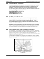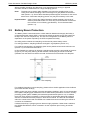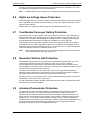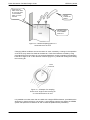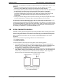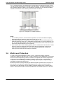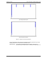
1
Power Generation Facilities Design Guide April, 2012 Doc 14158_01 VESDA by Xtralis Power Generation Facilities Design Guide Preface In this Design Guide we will discuss the relevant design considerations and make recommendations regarding the most effective way in which to install a VESDA solution in the particular power generation facilities for which it is being designed. Important Note: Doc. 14158_02 The information contained in this Design Guide should be used in conjunction with specific local fire codes and standards as well as the guidelines provided in the VESDA System Design Manual. Where applicable, other regional industry practices should also be adhered to. i VESDA by Xtralis Power Generation Facilities Design Guide Contents 1 Background Information .........................................................................................................1 1.1 1.2 1.3 1.4 2 Designing For Effective Protection ........................................................................................4 2.1 2.2 2.3 2.4 2.5 2.6 2.7 2.8 2.9 2.10 3 Standard Room on Ceiling Protection..........................................................................8 Inter-Beam Sampling.....................................................................................................9 Floor and Ceiling Void Protection .............................................................................. 10 Return Air Vent Protection .......................................................................................... 11 In/On-Cabinet Protection ............................................................................................ 13 Multi-Level Protection ................................................................................................. 14 Environmental Condition Considerations............................................................................ 16 4.1 4.2 4.3 4.4 5 Levels of Protection ......................................................................................................4 Control Room Protection ..............................................................................................5 Switch Room Protection ...............................................................................................5 Cable Tunnel and Cable Chamber Protection ..............................................................5 Battery Room Protection ..............................................................................................6 High/Low Voltage Annex Protection.............................................................................7 Coal Bunker/Conveyor Gallery Protection ...................................................................7 Generator/Turbine Hall Protection................................................................................7 Armature/Commutator Protection ................................................................................7 Escape Paths and Refuge Area Protection ..................................................................8 Common Protection Methods .................................................................................................8 3.1 3.2 3.3 3.4 3.5 3.6 4 Fire Safety Considerations in Power Generation Facilities .........................................1 Performance-Based Design ..........................................................................................1 Key Design Considerations ..........................................................................................2 Why Use VESDA Smoke Detection?.............................................................................2 High Background Pollution......................................................................................... 16 High Temperature Environments................................................................................ 16 Humid Environments .................................................................................................. 17 Hazardous Environments............................................................................................ 18 Ongoing Considerations....................................................................................................... 19 5.1 5.2 System Commissioning .............................................................................................. 19 Service and Maintenance ............................................................................................ 19 References ...................................................................................................................................... 20 Disclaimer On The Provision Of General System Design Recommendations ............................. 20 Doc. 14158_02 i Power Generation Facilities Design Guide ii VESDA by Xtralis Doc. 14158_02 VESDA by Xtralis Power Generation Facilities Design Guide 1 Background Information 1.1 Fire Safety Considerations in Power Generation Facilities The major fire risks and detection difficulties within Power Generation Facilities arise as a result of the following: The presence of high concentrations of mechanical equipment (turbines, crushers, conveyer belts, etc.) and the continuous operation of this equipment. Examples of possible causes of ignition are listed below. Electrical overheating of equipment, batteries and cables Friction in moving equipment elements Friction in failed bearings Electrical arcing and the build up of static electrical charge Hot coal (spontaneous combustion) transferred from the stockpile via conveyors Lubrication and hydraulic oils reaching maximum flash point. The presence of large amounts of flammable material (lubricant oils, gas, coal, plastics, etc.). For example, coal dust can settle on surfaces or penetrate equipment. Under favorable environmental conditions (low humidity and high temperature), this dust is highly explosive. The growth of fires in cable tunnels and cable chambers, beyond effective manual control or suppression, due to detection and access difficulties. The potential for explosion created by the minute quantities of hydrogen gas produced by lead acid batteries during the charge mode, where ventilation is poor and the hydrogenair vapour mixture exceeds the lower-explosive-limit (LEL). The undetected growth and spread of fire due to low staffing levels in most power generation facilities. The increased response times as a result of the remoteness of some areas of the plant. Smoke dilution in high ceiling areas and/or large open spaces pose a challenge to ceiling mounted detection devices. Forced air ventilation interferes with the normal dispersion of smoke and may dilute it or divert it away from ceiling mounted detectors, leading to a delayed or missed detection. Smoke cooled by air-conditioning may lack the thermal energy needed to reach ceiling mounted detectors, resulting in a stratified or diluted smoke concentration. High temperature or humidity levels can adversely affect the function of detection equipment. High dust levels contaminate the optical surfaces of conventional detectors and block the protective mesh around point (spot) type detectors, reducing their ability to detect smoke. 1.2 Performance-Based Design The unique environments within Power Generation Facilities present a challenge to both early and reliable fire detection. There is a high likelihood that detection system performance will be dependent on the environment within the facility, which will be dictated largely by the power generation procedures taking place within the area to be protected. The flexibility of Performance-Based Design, while still following rigorous engineering processes, allows the fire protection system to be tailored to the specific requirements of each individual application’s environment, with the commercial drivers to manage the risks. Detector spacing or, for a VESDA pipe, sample hole spacing is traditionally dictated by local prescriptive codes and standards. In a more performance-based approach, each installation is assessed according to its specific environmental conditions. Sample hole spacing and location can then be altered easily to suit the particular performance requirements. Doc. 14158_02 1 Power Generation Facilities Design Guide VESDA by Xtralis The Performance-Based Design approach is widely used since it can provide evidence to justify divergence from prescriptive requirements, particularly in cases where there are practical limitations or a need for an improved level of fire protection. There are some specific guidelines for the use of Performance-Based Design and risk management concepts. Examples of these codes and standards are listed below: NFPA 805 Performance-Based Standard for Fire Protection for Light Water Reactor [1] Electric Generating Plants . BS 7974 Application of fire safety engineering principles to the design of building – Code of practice[2]. [3] AS/NZ 4360 Risk Management Standard . SFPE (2000) Engineering Guide to Performance-Based Fire Protection, Analysis and [4] Design of Buildings . [5] SFPE Handbook of Fire Protection Engineering Third Edition . Performance-Based fire protection solutions can be made to comply with local and national codes and standards for buildings and life safety. Assessments of the environmental risks and performance requirements, specific to the particular Power Generation Facility, are conducted as part of the design process. 1.3 Key Design Considerations The following should be considered when designing a VESDA system for a Power Generation facility: 1 What are the characteristics of the area to be protected with respect to its ceiling height, contents (position, use, etc.), ventilation configuration and environmental conditions (temperature, humidity, chemicals present, atmospheric contaminants, etc.)? 2 What are the operational and functional conditions within each area to be protected? For example, will it be occupied by equipment only or will staff be present? If staff will be present, to what extent is the area manned? 3 What are the fire hazards within each area to be protected (ignition source, fuel type, density and location, etc.)? 4 Are there any other particular hazards in the area to be protected, explosive materials, highly combustible materials, radioactive substances, etc.? 5 What do local prescriptive codes recommend? 6 What, if any, do local Performance-Based Design codes recommend? 7 What do Power Generation Industry codes of practice dictate? 1.4 Why Use VESDA Smoke Detection? It is essential that fire events in Power Generation Facilities be detected as early as possible to minimize operational disruptions and asset damage and prevent environmental contamination. The limitations of conventional fire and smoke detectors (point (spot) type smoke, heat, flame and beam-type) must be considered (especially with increasing ceiling height). The comparatively low sensitivity and localized detection of point (spot) type detectors, for instance, can mean that fire events will not be detected soon enough in many cases. Power Generation Facility environments present the following challenges to conventional detectors: High ceilings result in significant smoke dilution (through clean air entrainment) during smoke plume rise. Point (spot) type smoke detectors, which rely on localized detection, may not be able to respond to diluted smoke plumes. Beam-type detectors lack the high sensitivity necessary for the detection of diluted smoke. Air movement, caused by mechanical or natural ventilation, will further dilute and cool the smoke plume, thus impairing the detection performance of point (spot) type smoke and heat detectors. 2 Doc. 14158_02 VESDA by Xtralis Power Generation Facilities Design Guide In high ceiling environments, the smoke plume from a small fire may not possess sufficient thermal energy to ascend to the ceiling. This impedes the detection of both point (spot) type smoke and heat detectors; smoke either does not reach the detection points or is too cool when it does. Point (spot) type smoke detectors mounted at the ceiling are subject to continuous environmental changes. These changes may force them to function outside their recommended operating range (temperature, humidity) and also compromise their detection performance, leading to false alarms or reduced sensitivity. Maintenance issues arise when conventional detection devices are installed in difficult to access areas or where maintenance requires equipment shutdown. For example, many local codes prohibit maintenance above active arc-resistant switch gear, so such equipment must be turned off while detectors are being maintained. Also remember – VESDA Maintenance in most countries is the same as point type detectors. Dust in a coal powered plant can affect the performance of detection systems by blocking the insect screens of (point (spot) smoke detectors) and obscuring the optical surfaces. Beam detection and flame detectors suffer similar issues. False alarms may occur when dust particles are mistaken for smoke and could result in costly downtime and subsequent re-power-up of the plant. The high density of equipment in many areas makes the use of beam and flame detectors unsuitable. Batteries may release electrolyte vapours into the air, which can create a slightly corrosive atmosphere. Sulphuric acid formation will damage conventional smoke detection systems. Conventional fire detection systems cannot detect the early stages of a fire. Heat detectors and sprinklers are designed to activate when the surrounding atmosphere reaches a specific temperature, approximately 57°C (135°F). So it is likely that a fire would have progressed to a critical stage by the time these detection systems are activated. Flame detectors respond to visible flame using Ultraviolet (UV) or Infrared (IR) technology, so a significant size of flame, from a reasonably large fire, would be required to trigger an alarm. The Very Early Warning Fire Detection (VEWFD) capability of an Xtralis VESDA system enables the minimization of fire risks and alleviation of detection challenges in the following ways: A VESDA system will detect smoke in high ceiling areas far quicker than that of point (spot) type or beam detectors due to its adjustable very sensitive alarm settings combined with the systems aggregation capability, i.e. Gathering smoke-laden air collected through sampling holes at different locations. Smoke stratification or thermal layering of the air may stop smoke reaching roof level. The VESDA system can be designed to compensate for this by allowing the positioning of sampling points at various heights to detect smoke. A VESDA system actively draws air through its sampling holes, which ensures a consistent detection performance in varying airflow conditions. The performance of point (spot) type smoke detectors relies on the direction and magnitude of airflows, in their vicinity, to carry smoke to the sensing chambers. Consequently, point (spot) type smoke detector performance constantly changes due to alterations in airflow conditions caused by ventilation. The very early warning capability of the VESDA system enables the detection of incipient (smouldering) and small energy fires. This provides facility operators with an opportunity to investigate and take action before the fire has a chance to spread. A VESDA system will enable rapid emergency procedures that will greatly reduce the potential for the release of pollutants from fire incidents into the environment. In addition, VESDA will increase the time available to execute an evacuation. In cases where gaseous or sprinkler fire suppression is part of the overall fire protection system, the VESDA detectors’ wide sensitivity range of 0.005 to 20%Obs/m (0.0015 to 6%Obs/ft) means that appropriate alarm thresholds can be set for both early detection and, at a later stage, the activation of the suppression release mechanisms. The fact that VESDA detectors can be placed in accessible locations means that they are easier to maintain, with no specialist equipment or equipment shutdown required. Doc. 14158_02 3 Power Generation Facilities Design Guide VESDA by Xtralis With easily accessible detectors, the majority of maintenance requirements, such as back flushing of the sampling pipe network, can be performed routinely and conveniently with little, if any, impact to day-to-day operations. VESDA’s filter technology physically removes most dust from the air sample before it enters the detection chamber. This, combined with electronic dust discrimination incorporated into embedded software, reduces the likelihood of false alarms and contamination of the optical surfaces. The filter status is continually monitored by a timer and a particle counter. The ability to network VESDA devices and monitor them remotely makes them ideal for the protection of large, widespread sites and remote locations such as pumping stations. Using the Autolearn function, a VESDA system can assess its environment and automatically set appropriate alarm thresholds for the levels of pollution present in the ambient air. 2 Designing For Effective Protection 2.1 Levels of Protection Regardless of the type of Power Generation Facility, there are areas common to all (control rooms, switch rooms, cable tunnels, cable chambers, etc.). Other areas are unique to a particular type of plant (biscuit barrel in Hydroelectric facilities or coal bunkers in Coal-Fired installations). The tables below show the levels of protection and protection methods for areas within Power Generation Facilities. Table 1 – Levels of protection in power generation and substation facilities. Areas Essential Recommended Switch/Relay Rooms On ceiling Cabinet Control Rooms On Ceiling Return Air Vent Cabinet Floor Void Cable Tunnels/Chambers On Ceiling Battery Rooms On Ceiling Return Air Vent High/Low Voltage Annexes On Ceiling Cabinet Coal Bunkers/Conveyor Galleries (Coal power generation) On Ceiling Return Air Vent (Subject to site inspection) Generator/Turbine Halls On Ceiling Cabinet Multi-Level Armature/Commutator Housing (Hydroelectric power generation) 4 Doc. 14158_02 VESDA by Xtralis 2.2 Power Generation Facilities Design Guide Control Room Protection The control room is the main command centre of any Power Generation Facility, the entire operation of the site being monitored and controlled from this location. Control rooms can range from small, unmanned, unventilated rooms to massive, air-conditioned areas with several staff and electronic equipment (PCs, control panels/consoles, electrical and electronic switching devices, underfloor cabling, etc.). Where air-conditioning is present, the following four sampling methods are recommended: On Ceiling Sampling (see section 3.1) Return Air Vent Sampling (see section 3.4) Cabinet Sampling (see section 3.5) Floor Void Sampling (see section 3.3) 2.3 Switch Room Protection The Switch Room is a dedicated space that accommodates a high concentration of electronic equipment, housed in cabinets, and automated switch-gear. The in-cabinet equipment maintains the primary functions of the power plant and forms the switching interface between the Control Room and the field equipment. Additionally, the area accommodates a significant amount of metering and logging equipment. Due to the high volume of critical electronic equipment, it is essential that a fire event be detected before the operation of the plant is compromised. Both standard room on-ceiling protection and cabinet protection are strongly recommended. The position of ceiling mounted sampling pipes will depend on the layout of the equipment within the switch room; hole spacing being governed by local codes and standards (section 3.1). Cabinet configuration will dictate where the sampling pipe is placed (section 3.5). 2.4 Cable Tunnel and Cable Chamber Protection In a typical facility, numerous lengths of cable tunnels link the Control Room, Switch Room and High/Low Voltage Annex areas. These cable tunnels generally range in size from 1 to 3 m (3 to 9.8 ft) wide and 2 to 3 m (6.5 to 9.8 ft) high. Cables are routed to their final destinations through cable chambers, small rooms 5 to 30 m (16 to 98 ft) square with ceiling heights of the same as the cable tunnels. The entire cable tunnel length can be protected by arranging detectors with their sampling pipe networks laid end to end, as shown (Figure 1). Sampling pipes are run along the centre of the top of the tunnel. Figure 1 – Example of a VESDA detector protecting a cable tunnel. Doc. 14158_02 5 Power Generation Facilities Design Guide VESDA by Xtralis Where possible, sampling pipe branches or two separate pipes running in opposite directions should be used instead of a single sampling pipe run. Note: The best way to protect cable chambers is to mount the sampling pipe on the ceiling such that the sampling holes are arranged in a grid pattern as discussed later (section 3.1). Some cable chambers possess support structures for the rooms above them. Inter-beam sampling (section 3.2) may be necessary in this case. Important Note: 2.5 Cable Tunnels and Cable Chambers exhibit extremely high levels of airborne particulate matter. For such dirty environments we recommend the inclusion of in line filtering (pre-filtration). This is discussed later (section 4.1). Battery Room Protection The Battery Room houses lead acid or nickel cadmium batteries that supply the facility’s uninterrupted power supply (UPS), to be used as a back-up power source and to start the facility in the event of a re-power-up. The size and configuration of the Battery Room is dependent on the power required by the UPS to operate the facility. On-ceiling and/or exhaust vent sampling can be used to protect battery rooms. For ceiling protection, sampling holes are arranged in a grid pattern (section 3.1). For exhaust vent sampling, the sampling pipes can be positioned across the exhaust vent (section 3.4) or inside the exhaust duct. In-Duct Sampling is achieved by locating a sampling pipe across the entire width of the duct (Figure 2). For very early warning smoke detection, air sampling should be conducted upstream from the filters to avoid the removal of smoke from the air before it is sampled. Figure 2 – Duct sampling. For detailed information on duct sampling, please refer to Xtralis’ Application Note for Ducts [6] (Document Number 10760) . Battery rooms may have a slightly corrosive atmosphere (sulphuric acid). It is recommended that a plastic sampling pipe network be used to eliminate the potential for corrosion, thereby providing greater system reliability and extended operational life (section 4.4). In addition there may be a need to incorporate a ‘Chemical Filter’ a special filter designed to absorb airborne contaminants that are present in these environments. The filter can be installed within the corrosive area and the VESDA unit outside the area thus reducing the effects of corrosion on the detector. If allowed to build up, hydrogen gas can become highly explosive. Under these conditions, the VESDA Exd detector, which is housed in its own explosion proof casing, should be installed. 6 Doc. 14158_02 VESDA by Xtralis Power Generation Facilities Design Guide We also recommend that VESDA detectors are mounted external to the battery room, with the exhaust pipe directed back into the protected area. Note: 2.6 Separate detectors are required for on ceiling and exhaust vent (duct) monitoring. High/Low Voltage Annex Protection High/low voltage annexes contain the voltage control and transmission equipment necessary for the operation of any Power Generation Facility. Much of the equipment housed in these areas occupies cabinets. Please refer to the options for cabinet protection discussed later (section 3.5). 2.7 Coal Bunker/Conveyor Gallery Protection Coal bunkers and conveyors exhibit a high concentration of coal dust. The combination of dust particulate with a low humidity level can expose the plant to a high fire risk due to the occurrence of combustion and deflagration. Heat from friction of rotating machinery parts and failed bearings (overheated) increases the possibility of fire from coal dust. Coal bunkers can be protected in a number of ways and represent difficult environments. Ceiling detection and, where appropriate, return air vent sampling can be applied. Both of these methods will be discussed later (section 3.1 and section 3.4). To combat stratification, multi-level sampling should be considered (section 3.6). Note: 2.8 We recommend the inclusion of in line filtering (pre-filtration) where environments are exceptionally dirty and dusty (section 4.1). Generator/Turbine Hall Protection Gas powered and hydroelectric power generation plants have generator halls, which are usually large volume areas with roof heights in excess of 10 m (33 ft). This area accommodates the site’s generators, associated cable network, electrical switching and control equipment normally housed in cabinets. An energy source rotates the turbines, which then drive the generator to produce electricity. The impact and consequence of a critical loss, and the cost of generator replacement, equipment repairs and revenue loss caused by a fire event make it imperative to install an early warning smoke detection system throughout the Generator Hall. On ceiling (section 3.1) multi-level (section 3.6) and cabinet protection (section 3.5) should all be used to protect this mission critical area. If a high temperature condition possibly exists inside the hall, proper procedures discussed later (section 4.2) should be applied. 2.9 Armature/Commutator Protection In hydroelectric Power Generation Facilities, the Armature and Commutator control the generation of electricity. The Commutator transposes electric current to operate the Armature, which powers the Exciters that drive the Generators to produce electricity. For safety reasons, the Armature and Commutator, along with their supporting cables, electric equipment, etc., are enclosed within a metal or concrete housing. Due to the operationcritical function of the Armature and Commutator, installing early warning smoke detection in the Commutator and Armature Housing is essential to prevent generation downtime, subsequent re-power up and the inevitable revenue loss. Doc. 14158_02 7 Power Generation Facilities Design Guide VESDA by Xtralis A single sampling pipe should be placed around the Commutator and Armature, following the curve of the housing (Figure 3). It is recommended that sampling holes are spaced at 500 mm (1.6 ft), with a maximum spacing of 1 m (3.3 ft). Clamps should be used to hold the pipe in position to avoid kinks or cracks developing when the sampling pipe is being bent. Figure 3 – VESDA sampling pipe curved around the Armature/Commutator housing Since the VESDA detector is external to the Armature/Commutator, issues surrounding access for maintenance are overcome. A return air pipe should be connected to the exhaust air port of the VESDA detector and returned to the Armature and/or Commutator Housing. Important Note: Where internal condensation is a possibility, water traps should be installed as discussed later (section 4.3). 2.10 Escape Paths and Refuge Area Protection The protection of escape routes and refuge areas is of the utmost importance to the safety of the Power Generation Facility staff during a fire event. These areas can be protected by on ceiling sampling with sampling holes in a grid pattern as discussed later (section 3.1) or inter-beam sampling (section 3.2) if appropriate. VESDA detectors can also be used to monitor the air quality in ducted systems to ensure that smoke-laden air is not allowed to enter occupied areas. In-duct sampling should be considered in this case (section 2.5). The VESDA alarm signal is used to initiate smoke management activities. 3 Common Protection Methods 3.1 Standard Room on Ceiling Protection The sampling pipe network is normally installed on the ceiling in such a way that the sampling holes form a grid pattern (Figure 4) and are located where conventional point (spot) type detectors would be positioned. Local codes and standards define different areas of coverage depending on certain criteria so you should refer to the relevant standards for sampling hole spacing requirements. 8 Doc. 14158_02 VESDA by Xtralis Power Generation Facilities Design Guide Figure 4 – Grid layout for standard room on ceiling sampling pipe network placement Important Note: 3.2 All sampling pipe network configurations should be verified using the TM ASPIRE2 Pipe Network Modeling Program. Inter-Beam Sampling In areas where the ceiling has beams or joists that create voids, there are two sampling options: Depending on the size of the voids and the depth of the beams, it may be necessary to sample within each inter-beam space or pocket in order to comply with local codes and standards. This type of sampling can be achieved using walking stick shaped capillary tubes from the main pipe into the inter-beam spaces (Figure 5). Figure 5 – Walking stick capillary tubes for inter-beam sampling and underside ceiling beam sampling Where local codes permit, sampling pipes can be run along the undersides of the beams with sampling hole spacing the same as that for flat ceilings. Doc. 14158_02 9 Power Generation Facilities Design Guide 3.3 VESDA by Xtralis Floor and Ceiling Void Protection The floor voids of some areas within Power Generation Facilities contain large quantities of electrical cabling. Often, airflow is extremely high within these spaces, increasing the probability of a rapid spread of fire. It is very important that these areas are protected. VESDA detectors are well suited to this task with detector positioning inside or outside the protected area where their location is more convenient for service and maintenance personnel. Mounting the detectors outside the protected area also minimizes any disruption to normal business operations during maintenance. In order to prevent the build up of dust and dirt, sampling holes are drilled on the underside of the sampling pipe (Figure 6). Sampling hole spacing is determined by the grid method shown previously (Figure 4). Figure 6 – Example of floor void protection Where there is a ceiling void, VESDA sampling pipes can be installed above the ceiling with capillary sampling through the ceiling into the protected area. The following should be adhered to when protecting floor or ceiling voids: The VESDA exhaust should be returned to the protected area in order to minimize the effects of possible pressure differences between the protected area and that in which the detector is located. Sampling pipes should be stand-off mounted to provide clearance from cabling at the top of the void. For voids with high air velocities (e.g. > 10 m/sec (2,000 fpm)), ideally, the sampling pipes 2 should be installed mid height. In facilities of larger than 1000 m (10,000 sq.ft), the sampling pipes can be arranged such that the sampling holes form a zigzag pattern to maximize coverage as shown below (Figure 7). Airflow Sampling Pipe Sampling Hole Return Air Figure 7 – Example of the zigzag arrangement of sampling holes in high airflow voids, to maximize coverage. 10 Doc. 14158_02 VESDA by Xtralis 3.4 Power Generation Facilities Design Guide Return Air Vent Protection The smoke from incipient electrical fires lacks thermal buoyancy and will most likely follow the path of the air circulated by the Air Handling Unit (AHU). The effect of this air movement on smoke detection at the ceiling can be overcome by complementing ceiling sampling with sampling across the return air vent of the AHU. Placing VESDA pipes on the return air vent as shown (Figure 8) can increase the reliability of smoke detection since smoke will be detected as early as possible. Airflow AHU Cabinets Figure 8 – Example of return air vent protection. [7] 2 NFPA 76 recommends a maximum area of coverage per sampling hole of 0.4 m (4 sq.ft). For small vents, the VESDA detector recommended maximum area of coverage per 2 sampling hole may be reduced to 0.2 m (2 sq.ft). For example, a vertical return air vent of dimensions 1.5 by 0.8 m (5 by 2.6 ft) would require six sampling holes (Figure 9). Figure 9 – Example of Xtralis’s and BFPSA recommended number of sampling holes on a vertical return air vent 1.5 by 0.8 m (5 by 2.6 ft). Note: TM The ASPIRE2 Pipe Network Modelling Tool must be used to ensure that the transport time is within acceptable limits. For both vertical (Figure 9) and horizontal (Figure 10) return air vents, VESDA pipes should be positioned 100 to 200 mm (4 to 8") away (using stand-offs) from the return air vent to avoid the low air pressure areas at the entry of the vent. Doc. 14158_02 11 Power Generation Facilities Design Guide VESDA by Xtralis X denotes the width of the return air vent. No pipes to be installed within ¼ X from the wall. Arrows indicate the airflow. Sampling pipes to be installed within ¾ X. Figure 10 – VESDA sampling pipes on a horizontal return air vent. Changing airflow conditions across the return air vents, caused by a change in the operation of the AHU, may cause flow faults at the detector. These flow faults are avoided by using pipe stand-offs from the return air vent, as described above, and by orientating the sampling holes at an angle of 30° to the direction of airflow (Figure 11), rather than having them facing the incoming air. Airflow Streamlines Figure 11 – Example of a sampling hole at a 30° angle to the incoming air on a horizontal return air vent. It is possible to monitor more than one AHU with a single VESDA detector, provided that the AHUs are in close proximity to one another. A good design practice is to restrict the VESDA system transport time to between 30 and 40 seconds (determined by ASPIRE2). 12 Doc. 14158_02 VESDA by Xtralis Power Generation Facilities Design Guide In summary, it is important to consider the following points when designing for return air vent protection: The use of sampling pipe stand-offs from the return air vent (Figure 10) is critical, especially when multiple AHUs are being monitored by the same detector. For very early warning smoke detection, air sampling should be conducted upstream from the AHU filters to avoid the removal of smoke from the air before it is sampled. In cases where the AHU being monitored requires front access for maintenance, removable VESDA pipes must be used. These pipes have special socket junctions to ensure the correct pipe orientation with respect to the airflow direction (30°) on reconnection. Good pipe network design practices such as minimizing the total pipe length and number of bends should also be considered. Non-vented end-caps are recommended. It is essential to test the system performance, with the AHUs in their normal operating mode and turned off, to check that sampling pipe position and orientation are correct. The movement of smoke towards the AHU may be impeded by the cabinets. It is a good practice to use VESDA detectors to monitor the entire area (ceiling, voids and return air vents), hence providing an integrated total early warning solution. All sampling pipe network designs must TM be verified by the ASPIRE2 Pipe Network Modelling Tool. 3.5 In/On-Cabinet Protection Cabinets containing electrical equipment are usually ventilated either vertically (from bottom to top) or horizontally (from front to back). There are also fully enclosed cabinets with active internal cooling and ventilation. Fires within these areas may not be detected until they have been in progress for some time and have caused considerable damage to the housed equipment. There are two methods for protecting cabinets with VESDA detectors: In Cabinet Protection. On Cabinet Protection. In cabinet protection can be achieved using either of the following options: 1. The sampling pipe of a detector is placed inside the cabinet. This provides optimum detection and is commonly used by cabinet OEMs (Original Equipment Manufacturers) for both sealed and ventilated cabinets. In ventilated cabinets (both vertical and horizontal), air is sampled as it reaches the exit points. 2. A capillary tube (A) or down pipe (B) can be inserted into the top of the cabinet from the main VESDA ceiling mounted sampling pipe as shown (Figure 12). This arrangement is suitable only for sealed cabinets or cabinets with little ventilation. When using down pipes, end-caps with appropriate sampling holes should be fitted. Figure 12 – Example of a capillary tube (A) and down pipe (B) used for in cabinet sampling. Doc. 14158_02 13 Power Generation Facilities Design Guide VESDA by Xtralis For on cabinet protection, the sampling pipe is placed above the cabinets as shown (Figure 13) with sampling holes directly in the path of the main airflow, to optimize the detection of a fire originating inside the cabinet. This arrangement is suitable only for vertically ventilated cabinets. One detector can be used to protect a number of cabinets. Figure 13 – Example of on cabinet protection. Notes: For in cabinet protection, unless otherwise specified, it is recommended that capillary tubes penetrate the cabinet to a depth of 25 to 50 mm (1 to 2”). When rapid response to an incipient fire event is required, individual VESDA detectors or dedicated sampling pipes from an addressable VESDA detector (such as VESDA VLS or IFT-15) can be used to identify the location of the smoke source. Fire events can then be traced to a particular cabinet or row of cabinets. Care must be taken when installing capillary tubes in cabinets with extraction fans. These fans may cause low pressures within the cabinet which could prevent air and hence smoke entering the sampling hole. In this case, sampling downstream (outside the cabinet) from the extraction fans may be considered. 3.6 Multi-Level Protection In areas where smoke stratification is likely to occur, multi-level sampling should be employed in addition to standard room on-ceiling sampling. Smoke stratification occurs when there is a vertical temperature gradient. Variations in temperature at different heights affect smoke movement upwards and can delay its detection at the ceiling. A sampling hole configuration for one VESDA pipe network (a) ceiling dropdown pipes, or (b) vertical pipe orientation is shown below (Figure 14). Multi-level protection employs sampling at different heights to penetrate the hot air layer at the roof level, which allows for optimal sampling when the air at the roof level is either abnormally hot or abnormally cold. By installing a vertical sampling pipe, air and smoke is drawn in from different heights, overcoming stratification and reducing the time to detection. 14 Doc. 14158_02 VESDA by Xtralis Power Generation Facilities Design Guide (a) Ceiling dropdown pipes (b) Vertical pipe orientation Figure 14 – Options for multi-level protection. A fire risk assessment of the environment will determine the likely stratification layer height. Sampling holes must be located within the stratification layer. Important Note: Doc. 14158_02 Local codes and standards should be consulted to determine the permissible length of dropdown pipes or sampling hole height (Figure 14). 15 Power Generation Facilities Design Guide VESDA by Xtralis 4 Environmental Condition Considerations 4.1 High Background Pollution In areas that exhibit extremely high levels of airborne particulate matter (coal dust, lint, etc.), we recommend the inclusion of in line filtering (pre-filtration) as part of the VESDA system design. Filters (such as E700-FILASSY) are placed, external to the detector, in the sampling pipe network to collect the particulate matter before the air sample enters the detector. In-line filtering also helps to extend the life of the on-board VESDA filter. For detailed information on in line filtering, please refer to Xtralis Application Note, In-line Filter for Harsh [8] and Dirty Environments (Document Number 10856 ). 4.2 High Temperature Environments For optimum operation, VESDA detectors MUST be installed in a location where the ambient [9] temperature is within the normal operating temperature range of the units . High temperature sampled air can be easily cooled down, before it reaches the detector, by extending the sample pipe length beyond its point of exit from the protected area. The relatively cooler air outside the pipe near the detector will cool the warm sampled air within it. Usually, only a short pipe extension is necessary. 40 12 40 L/min 35 10 30 PVC Pipe Length (ft) PVC Pipe Length (m) The charts below (Figure 15 to Figure 17) provide conservative estimates of the pipe extensions required to decrease the temperature of the sampled air to an acceptable value for a number of commonly used pipe materials and range of flow rates. All calculations assume an external ambient temperature of 20°C (68°F) and a sampled air temperature of 60°C (140°F). 8 30 L/min 25 6 20 20 L/min 15 4 10 2 5 0 100 / 212 0 90 / 194 80 / 176 70 / 158 60 / 140 Sampled Air Temperature (°C / °F) Figure 15 – Chart showing the estimated PVC pipe extension for cooling sampled air. 16 Doc. 14158_02 Power Generation Facilities Design Guide 12 40 40 L/min 35 10 30 8 ABS Pipe Length (ft) ABS Pipe Length (m) VESDA by Xtralis 25 30 L/min 6 20 20 L/min 15 4 10 2 5 0 100 / 212 0 90 / 194 80 / 176 70 / 158 60 / 140 Sampled Air Temperature (°C / °F) 20 6 40 L/min 5 16 4 Cu Pipe Length (ft) Cu Pipe Length (m) Figure 16 – Chart showing the estimated ABS pipe extension for cooling sampled air. 12 30 L/min 3 8 2 20 L/min 4 1 0 100 / 212 0 90 / 194 80 / 176 70 / 158 60 / 140 Sampled Air Temperature (°C / °F) Figure 17 – Chart showing the estimated Copper pipe extension for cooling sampled air. 4.3 Humid Environments Water traps are necessary under vastly varying environmental conditions where internal sampling pipe condensation is a possibility. An example of a water trap is shown below (Figure 18). Doc. 14158_02 17 Power Generation Facilities Design Guide VESDA by Xtralis Figure 18 – Example of a water trap. To install a water trap, a U section of pipe must be fitted to the pipe entering an inverted VESDA detector. Water will pool at the stop valve on the downwards pointing arm of the U. The transparent section of pipe allows maintenance personnel to see when water is building up, before it rises above the intersection with the main sampling pipe, and release it via the stop valve. An end cap could be put on the pipe in place of the stop valve. If no condensation is evident after some time, the water trap can be removed. Important Note: 4.4 Water trap stop valves and end caps MUST be replaced as soon as the water has been drained. Leaving the pipe open will affect the airflow. Hazardous Environments In protected areas containing hazardous airborne material such as corrosive air, etc., we recommend that VESDA detectors are installed outside the protected area, within an IP enclosure, with the exhaust pipe directed back into the protected area. Proper sealing of all the pipe joints and internality of whole pipe network should be maintained all the time. An analysis of the nature of the environment should be conducted to select the most appropriate sampling pipe materials. For example, plastic pipe is needed in battery rooms to eliminate the potential for corrosion by sulphuric acid but, in radioactive environments, metallic pipe should be used. Sampled air should be conditioned prior to it entering the sensing chamber. Conditioning can be in the form of adsorbents or absorbents placed inside an in-line filter plastic container. This involves replacing the Coarse and Medium filtering elements with beads appropriate to the target environmental contaminant. Important Note: 18 Air from the VESDA exhaust pipe MUST be returned to the area from which it was sampled. The return pipe from the exhaust should be as short as possible. The inlet and exhaust pipe penetrations to the protected area MUST be air-tight and properly sealed according to the degree of hazard. Doc. 14158_02 VESDA by Xtralis Power Generation Facilities Design Guide 5 Ongoing Considerations 5.1 System Commissioning Once the VESDA system has been installed, its performance and pipe network integrity can be verified using the ASPIRE2 pipe modelling program. A range of sampled air temperatures may be input to determine Maximum Transport Times for each zone. Calculated Transport Times should be applied conservatively. Smoke tests can then be used to check system performance for both smoke detection and pre-action suppression activation. 5.2 Service and Maintenance The VESDA system shall be serviced and maintained according to both the local codes and standards and the instructions provided in the Maintenance section of the VESDA System [9] Design Manual . Important Note: WARNING: Doc. 14158_02 Codes governing the disposal of radioactive substances MUST be adhered to when cleaning VESDA sampling pipe networks within areas where it is likely that the sampling pipes may be contaminated. More frequent maintenance of VESDA detector parts may be required should those parts be susceptible to damage as a result of exposure to radiation. Xtralis accepts no liability for events or circumstances arising from contamination or damage to the VESDA system as a result of radioactive contamination and cannot provide any guarantees with regard to system performance within this type of hazardous environment. 19 Power Generation Facilities Design Guide VESDA by Xtralis References [1] NFPA 805 (2006) Performance-Based Standard for Fire Protection for Light Water Reactor Electric Generating Plants. [2] BS 7974 (2001) Application of fire safety engineering principles to the design of building – Code of practice. [3] Australian Standard AS/NZ 4360 (1999) Risk Management Standard. [4] SFPE (2000) Engineering Guide to Performance-Based Fire Protection, Analysis and Design of Buildings. [5] SFPE (2002) Handbook of Fire Protection Engineering, 3rd Edition. [6] NFPA 76 (2005) Recommended Practice for the Fire Protection of Telecommunications Facilities. [7] Xtralis (2007) Ducts Application Note. [8] Xtralis (2007) In-line Filter For Harsh And Dirty Environments Application Note. [9] Xtralis (2006) VESDA System Design Manual, Ed. 4.5. Disclaimer On The Provision Of General System Design Recommendations Any recommendation on system design provided by Xtralis is an indication only of what is considered to be the most suitable solution to meet the needs of the common application environments described. In some cases the recommendations on system design provided may not suit the unique set of conditions experienced in a particular application environment. Xtralis has made no inquiry nor undertaken any due diligence that any of the recommendations supplied will meet any particular application. Xtralis makes no warranty as to the suitability or performance of any recommendation on system design. Xtralis has not assessed the recommendation on system design for compliance with any codes or standards that may apply nor have any tests been conducted to assess the appropriateness of any recommendations on system design. Any person or organization accessing or using a recommendation on system design should, at its own cost and expense, procure that the recommendation on system design complies in all respects with the provision of all legislation, acts of government, regulations, rules and by-laws for the time being in force and all orders or directions which may be made or given by any statutory or any other competent authority in respect of or affecting the recommendation on system design in any jurisdiction in which it may be implemented. Xtralis products must only be installed, configured and used strictly in accordance with the General Terms and Conditions, User Manual and product documents available from Xtralis. Xtralis accepts no liability for the performance of the recommendation on system design or for any products utilized in the implementation of the recommendation on system design, aside from the General Terms and Conditions, User Manual and product documents. No statement of fact, drawing or representation made by Xtralis either in this document or orally in relation to this recommendation on system design is to be construed as a representation, undertaking or warranty. To the extent permitted by law, Xtralis excludes liability for all indirect and consequential damages however arising. For the purposes of this clause, ‘consequential damage’ shall include, but not be limited to, loss of profit or goodwill or similar financial loss or any payment made or due to any third party. Recommendations on system design are provided exclusively to assist in design of systems using Xtralis products. No portion of this recommendation on system design can be reproduced without the prior approval in writing of Xtralis. Copyright and any associated intellectual property in any such recommendations on system design or documentation remains the property of Xtralis. 20 Doc. 14158_02 VESDA by Xtralis Power Generation Facilities Design Guide www.xtralis.com The Americas +1 781 740 2223 Asia +852 2916 8876 Australia and New Zealand +61 3 9936 7000 UK and Europe +44 1442 242 330 Middle East +962 6 588 5622 The contents of this document are provided on an “as is” basis. No representation or warranty (either express or implied) is made as to the completeness, accuracy or reliability of the contents of this document. The manufacturer reserves the right to change designs or specifications without obligation and without further notice. Except as otherwise provided, all warranties, express or implied, including without limitation any implied warranties of merchantability and fitness for a particular purpose are expressly excluded. This document includes registered and unregistered trademarks. All trademarks displayed are the trademarks of their respective owners. Your use of this document does not constitute or create a licence or any other right to use the name and/or trademark and/or label. This document is subject to copyright owned by Xtralis AG (“Xtralis”). You agree not to copy, communicate to the public, adapt, distribute, transfer, sell, modify or publish any contents of this document without the express prior written consent of Xtralis. Doc. 14158_02