1
PISO-PS300 User Manual
Version 4.0
05/2005
PISO-PS300
3 axis stepping/servo control board
User Manual
Version 4.0 05/2005 Edition
Driver update : http://www.icpdas.com
Warranty: All products manufactured by ICP DAS are warranted against
defective materials for one year from the date of delivery to the original
purchaser
Warning: ICP DAS assumes no liability for damage consequent to the
use of this product. ICP DAS reserves the right to change this manual at
any time without notice. The information furnished by ICP DAS is
believed to be accurate and reliable. However, no responsibility is
assumed by ICP DAS for it’s use, nor for any infringements of patents or
other rights of third parties resulting from it’s use.
Copyright
Copyright 2001 by ICP DAS. All right are reserved
Trademark
The names used for identification only maybe registered trademarks of
their respective companies.
http://www.icpdas.com
4-1
ICPDAS
PISO-PS300 User Manual
PISO-PS300
Version 4.0
05/2005
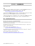
3 axis PCI bus stepping/servo motor
control board
PISO-PS300 is a 3-axis, command-type, stepping/servo motor control
board. The embedded CPU of PISO-PS300 performs the motion command
transferred from host-PC via a 2K bytes FIFO. It also sends the positions and
status back to host-PC via another 2K bytes FIFO. This buffer provides time
buffer, so, it is very suitable for windows operating system. This board
provides DOS, windows 95 and windows NT drivers.
Features
• 3-axis pulse output stepping/servo PCI control card.
• PCI bus
• Maximum output pulse rate: 1MHz.
• Simulation mode / real mode.
• Encoder/pulse read back.
• Programmable output mode: CW/CCW, Pulse/Direction
• 3-axis linear interpolation, 2-axis circular interpolation.
• Programmable trapezoidal speed profile.
• Programmable DDA period.
• Programmable direction configuration.
• Programmable 2 speed home return, home preset, home direction.
• Home, forward, backward limit switches per axis.
• Hardware emergency stop, software emergency stop.
• Limit switch auto-protection.
• Programmable limit switch normal state: N.O. (normal open) or N.C.
•
•
•
•
•
(normal close).
8 digital inputs, 7 digital outputs.
2500V optical isolation.
Embedded CPU, totally 45 command set.
DOS, windows 95/98, windows NT DLL driver.
BCB, VB, Delphi driver.
Option
• DB-8R Daughter board.
http://www.icpdas.com
4-2
ICPDAS
PISO-PS300 User Manual
Version 4.0
05/2005
PISO-PS300 Contents
1. Introduction
4-4
1.1 System Block Diagram
4-4
1.2 DDA technology
4-5
1.3 The operating mode
4-8
2. Hardware
4-10
2.1 Hardware address selection
4-10
2.2 Registers of PISO-PS300 Board
4-10
2.3 Hardware configuration
4-12
2.3.1 Limit switch configuration
4-12
2.3.2 Direction configuration
4-13
2.3.3 Turn Servo ON/OFF
4-13
2.4 Auto-protection
4-14
2.5 Connection
4-15
3. Software
4-22
3.1 The required software skeleton
4-22
3.2 Functions
4-25
3.2.1 Loading and unloading driver commands (only for windows)
4-26
3.2.2 Setting commands
4-26
3.2.3 Stop commands
4-29
3.2.4 Motion commands
4-31
3.2.5 Get information
4-40
3.2.6 Others
4-43
3.2.7 New interpolation command
4-45
4. Driver
4-50
DOS Driver(C, C++), Windows 95 Driver, Windows NT Driver 4-50
5. Example
4-51
5.1 DOS example
4-51
5.2 Windows example
4-52
6. Application notes
4-53
6.1 Functional testing
4-54
6.2 Hand wheel input
4-56
7. PISO-PS300 new function
http://www.icpdas.com
4-3
ICPDAS
PISO-PS300 User Manual
Version 4.0
05/2005
1. Introduction
_
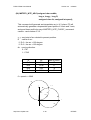
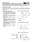
1.1 System Block Diagram
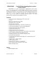
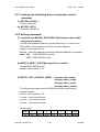
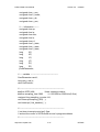
PISO-PS300 is a microprocessor based and 3- axis pulse type (max. pulse
rate: 1MHz) stepping/servo motion control board. It contains a 2K bytesFIFO to receive motion command from host PC, and it also sends the
positions and status back to host-PC via the other 2K bytes FIFO. The
motion profile is generated by microprocessor. This microprocessor also
handles auto-protection function. Each digital I/O supports 2500Vrms
optical isolation.
2K FIFO
CPU
Interface Buffer
3
DDA
Profile Generation
Protection
2K FIFO
PCI
BUS
Interface Buffer
Connector
CPU Status
3
encoder
counter
Limit Switch
Input Port
Optical
Isolation
8 digital input
Connector
7 digital output
Figure(1) block diagram of PISO-PS300
http://www.icpdas.com
4-4
ICPDAS
PISO-PS300 User Manual
Version 4.0
05/2005
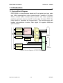
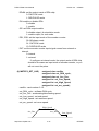
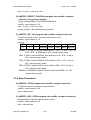
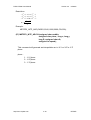
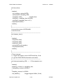
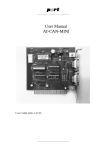
1.2 DDA Technology
The DDA chip is heart of PISO-PS300 card, it will generate equal-space
pulse train corresponding to specific pulse number during a DDA period.
This mechanism is very useful to execute pulse generation and
interpolation function. The DDA period can be determined by DDA cycle.
Table(1) shows the relation among DDA cycle, DDA period and output
pulse rate. When DDA cycle set to 1, the DDA period is equal to
(1+1)x1.024ms = 2.048ms. The output pulse number can be set to 0~2047,
therefore the maximum output pulse rate will be 1Mpps. The minimum
output pulse rate is 3.83pps when set DDA cycle=254 (DDA period =
(254+1)x1.024ms = 261.12ms).
DDA period
DDA cycle
X pulse = 3
Y pulse = 6
Z pulse = 4
Figure(2) DDA mechanism
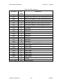
Table(1) The Relation among DDA cycle, DDA period and output pulse rate.
DDA cycle
DDA period
Max. pulse
rate(n=2047)
Min. pulse rate (n=1)
1
2.048ms
999511pps
488pps
2
3.072ms
666341pps
325pps
3
4.096ms
.
.
.
.
.
.
N
(N+1)*1.024ms
2047/(DDA period)
1/(DDA period)
.
.
.
.
254
261.12ms
7839pps
3.83pps
The DDA cycle can be set by MSTEP3_SET_VAR() command which
decribed in charpter 3. The selection criterion of DDA cycle was described
as following.
http://www.icpdas.com
4-5
ICPDAS
PISO-PS300 User Manual
Version 4.0
05/2005
(1) The required max. output pulse rate.
PRmax = Vmax*N/60
2047
PRmax = ( DDAcycle + 1) * 1. 024ms
PRmax : max. output pulse rate.
Vmax : max. speed (rpm).
N
: the pulse number of stepping motor per revolution.
(pulse/rev).
2. The required speed resolution.
The maximum output pulse number is Np(0~2047), therefore
the speed resolution is Vmax(max. speed)/Np. The DDA cycle
can be obtained by following equation.
Np
PRmax = ( DDAcycle + 1) * 1. 024ms
3. When choose large DDA cycle (DDA period), it will occur
vibration between different pulse input which generally can be
observed during acceleration or deceleration. So, the small
DDA cycle , the smooth acceleration/deceleration curve as long
as the speed resolution is acceptable.
Example: Stepping Motor
The specification of stepping motor is 500 pulse/rev, max. speed 500
rpm, speed resolution 2 rpm.
The required max. pulse rate
PRmax = 500 rpm*500/60 = 4166.67 pps
The maximum output pulse
Np = 500rpm/2rpm =250 pulse number
The DDA cycle can be calculated by follow equation
Np
PRmax = ( DDAcycle + 1) * 1. 024ms
250
4166.67 = ( DDAcycle + 1) * 1. 024ms
DDA cycle = 58
http://www.icpdas.com
4-6
ICPDAS
PISO-PS300 User Manual
Version 4.0
05/2005
High Speed = 247 pulse (4166.67*58*0.001024)
The above results means that maximum speed is 500rpm when send
command MSTEP3_SET_VAR(0, 58, 2, 2, 247, 50) to PISO-PS300 card.
Example: Pulse type input Servo Motor
The specification of servo motor is 8000 pulse/rev, max. speed 3000 rpm,
speed resolution 2 rpm.
The required max. pulse rate
PRmax = 3000 rpm*8000/60 = 400,000 pps
The maximum output pulse
Np = 3000rpm/2rpm =1500 pulse number
The DDA cycle can be calculated by follow equation
Np
PRmax = ( DDAcycle + 1) * 1. 024ms
1500
400,000 = ( DDAcycle + 1) * 1. 024ms
DDA cycle = 3
High Speed = 1638 pulse (400,000*4*0.001024)
The above results means that maximum speed is 3000rpm when send
command MSTEP3_SET_VAR(0, 3, 2, 2, 1638, 100) to PISO-PS300
card.
http://www.icpdas.com
4-7
ICPDAS
PISO-PS300 User Manual
Version 4.0
05/2005
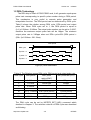
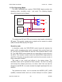
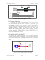
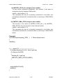
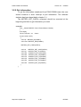
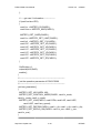
1.3 The Operating Mode
For easily developing your system, PISO-PS300 board provides two
operating mode: simulation mode / real mode. The following diagram
shows the internal circuit of board
OE
1
DDA chip
3
CW
3
CCW
2
2 output mode:
CW/CCW
DIR/Pulse
1
2
Encoder counter
A
3 input mode:
AB phase
CW/CCW
DIR/Pulse
B
EXT
The output pins CW and CCW can be set as output enable or disable by
OE signal. The encoder counter source signal can be connect to outside
(A/B) or internal DDA chip by EXT signal.
Simulation mode
In simulation mode, the PISO-PS300 control board will simulate the
motion profile according to the motion command that received from host
PC, and then the PISO-PS300 will send the 3-axis positions back to host
PC. The PISO-PS300 control board will not output pulse to motor driver by
set OE=0. The encoder counter counts the internal DDA output pulse by
set EXT=0. Therefore, the positions which read from the encoder counter is
really output pulse number.
This mode is very useful and efficient in the design phase. The
simulation mode can be operated off from machine. The user can debug
and develop the software previously or at home. And if the user has the
daughter board DB-8R, it can also simulate the digital input/output like as a
machine.
The positions and status can be received from MSTEP3_GET_CARD
(cardNo) command which must use a timer interrupt to receive, please
http://www.icpdas.com
4-8
ICPDAS
PISO-PS300 User Manual
Version 4.0
05/2005
refer to chapter 3 software.
Real mode
In real mode, the output mode of DDA chip can be set as CW/CCW or
DIR/PULSE mode according to user’s motor driver, and set OE=1 for
output enable. Setting EXT=1, the source signal of encoder counter come
from external input. The input mode of encoder counter could be three kind
mode: AB phase, CW/CCW and DIR/PULSE.
Software emergency stop
The servo command can be terminated from host-PC using software
control.
The
user
can
use
MSTEP3_STOP_ALL()
or
MSTEP3_EMG_STOP() command to terminate the servo commands which
is executing in PISO-PS300 board. This command can clear all the
commands pending in FIFO buffer.
http://www.icpdas.com
4-9
ICPDAS
PISO-PS300 User Manual
Version 4.0
2 Hardware
05/2005
_
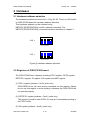
2.1 Hardware address selection
The hardware address can be set as 0~15 by A0~A3. There is a DIP switch
on PISO-PS300 board for hardware address selection.
This hardware address can be selected using
MSTEP3_REGISTRATION( cardNo, address) command. The
MSTEP3_REGISTRATION() command has been described in chapter 3.
0x00 =
A0 A1 A2 A3
0x0F =
A0 A1 A2 A3
Figure(3) Hardware address selection
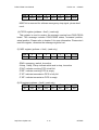
2.2 Registers of PISO-PS300 board
The PISO-PS300 has 6 registers including FIFO1 register, FIFO2 register,
RSTFIFO1 register, DI register, DO register and MSC register.
(1) FIFO1 register (pcibase + 0xc0) (write only)
PISO-PS300 driver will send motion command via this register. Please
do not use this register to write anything, otherwise the PISO-PS300 will
not operate properly.
(2) RSTFIFO1 register (pcibase + 0xc4) (write only)
This register is used to reset FIFO1 for clear all of commands pending in
the FIFO1 buffer.
(3) DO register (pcibase + 0xc8) (write only)
http://www.icpdas.com
4-10
ICPDAS
PISO-PS300 User Manual
Version 4.0
05/2005
MSB 7
6
5
4
3
2
1
0 LSB
EMG
DO6
DO5
DO4
DO3
DO2
DO1
DO0
MSB7 bit is reserved for software emergency stop signal, please don't
use it.
(4) FIFO2 register (pcibase + 0xc0) (read only)
This register is used to receive the message coming from PISO-PS300
board. This message includes PISO-PS300 status, command position,
actual position. Please refer to chapter 3 for more information. Please don’t
read this register, otherwise the message might be lost.
(5) MSC register (pcibase + 0xc4) (read only)
MSB 7
6
5
4
3
2
1
0 LSB
/EMG /Zstop /Ystop /Xstop /F2HF /F2EF /F1FF /F1EF
/EMG: emergency switch, low active.
/Xstop, /Ystop, /Zstop: indicate which axis is stop, low active
/F2HF: indicate receiving FIFO is half full.
/F2EF: indicate receiving FIFO is empty.
/F1FF: indicate transmissive FIFO is fully full.
/F1EF: indicate transmissive FIFO is empty.
(6) DI register (pcibase + 0xc8) (read only)
MSB 7
6
5
4
3
2
1
0 LSB
di7
di6
di5
Di4
Di3
di2
di1
di0
http://www.icpdas.com
4-11
ICPDAS
PISO-PS300 User Manual
Version 4.0
05/2005
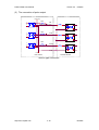
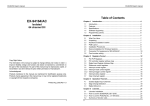
2.3 Hardware Configuration
2.3.1 Limit switch configuration
The profile generation and protection is executed by the CPU of PISOPS300 board, The limit switches must be configured as the following
figure, otherwise the motion command won’t work properly,.
CCW/BW
CW/FW
Motor
ccm
XLS- XI
XLS+
/XLS/XI
/XLS+
EXT_GND
/EMG
X axis
Emergency
Figure(4) Limit switch configuration of X axis
CCW/BW
CW/FW
Motor
ccm
YLS- YI
YLS+
/YLS/YI
/YLS+
EXT_GND
Y axis
Figure(5) Limit switch configuration of Y axis
http://www.icpdas.com
4-12
ICPDAS
PISO-PS300 User Manual
Version 4.0
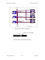
CCW/BW
05/2005
CW/FW
Motor
ccm
ZLS- ZI
ZLS+
/ZLS/ZI
/ZLS+
EXT_GND
Z axis
Figure(6) Limit switch configuration of Z axis
2.3.2 Direction configuration
Sometimes, the output direction of X-axis, Y-axis, Z-axis is not in
the desired direction due to motor connection or gear train. It is
recommended to unify the output direction as shown in Figure(4)(5)(6).
The CW/FW direction is defined as toward outside from motor and the
CCW/BW direction is defined as toward inside to motor. The
MSTEP3_SET_DEFDIR(cardNo, defdirX, defdirY, defdirZ) command
provides parameters NORMAL_DIR (0) and REVERSE_DIR (1) to
define the rotating direction of motor.
2.3.3 Turn Servo ON/OFF (Hold ON/OFF)
The MSTEP3_SET_SERVO_ON(cardNo, sonX, sonY, sonZ) command
provides parameters ON (1) and OFF (0) to turn Servo ON or OFF. The
internal circuit of Servo-ON is sink-type connection as the following
figure.
FVCC (5V)
330R
1
3
6
5
4
OPEN COLLECTOR
SONX
SONY
SONZ
FGND
Figure(7) internal circuitry of Servo-ON signal
http://www.icpdas.com
4-13
ICPDAS
PISO-PS300 User Manual
Version 4.0
05/2005
2.4 Auto-protection
PISO-PS300 board supports a automatic protection system.
(a) When X(Y)(Z)-axis command is executed and the motor moves
toward CW/FW direction, all axis will immediately stop when XLS+
(YLS+) (ZLS+) is touched. To release this protection, the X(Y)(Z)-axis
must move toward CCW/BW direction.
(b) When X(Y)(Z)-aixs command is executed and the motor moves
toward CCW/BW direction, all axis will immediately stop when XLS(YLS-) (ZLS-) is touched. To release this protection, the X(Y)(Z)-axis
must move toward CW/FW direction.
(c) When any of the /EMG switches is touched, all motion command will
be terminated and all motors will stop immediately. Meanwhile, the
servo ON signal will be automatical turn off for rotating the shaft by
manual. The servo ON signal will recover after released the /EMG
switches.
http://www.icpdas.com
4-14
ICPDAS
PISO-PS300 User Manual
Version 4.0
05/2005
2.5 Connection
(1) Pin assignment
Table(1) CN2 connector
pin name
pin
number
description
CW_PULSEX
1
CW or PULSE output of X axis
CCW_DIRX
2
CCW or DIR ground of X axis
CW_PULSEY
3
CW or PULSE output of Y axis
CCW_DIRY
4
CCW or DIR ground of Y axis
FGND
5
Isolated ground
SONX
6
servo on signal of X axis
FVCC
7
Isolated 5V output, max. 25mA
SONY
8
servo on signal of Y axis
9
No used
Table(2) CN3 connector
pin name
pin
number
CW_PULSEZ
1
CW or PULSE output of Z axis
CCW_DIRZ
2
CCW or DIR ground of Z axis
SONZ
3
servo on signal of Z axis
FVCC
4
Isolated 5V output, max. 25mA
FGND
5
Isolated ground
/ZI
6
home index switch of Z axis, active low for N.O.
/ZLS+
7
Positive limit switch of Z axis, active low for N.O.
/ZLS-
8
Negative limit switch of Z axis, active low for N.O.
VEXT
9
external power (apply 12~24V)
http://www.icpdas.com
Description
4-15
ICPDAS
PISO-PS300 User Manual
Version 4.0
05/2005
Table(3) CN4 connector
pin name
pin
number
/XLS+
1
Positive switch of X axis, active low for N.O.
/XLS-
2
Negative limit switch of X axis, active low for N.O.
/YLS+
3
Positive limit switch of Y axis, active low for N.O.
/YLS-
4
Negative limit switch of Y axis, active low for N.O.
/XI
5
home index switch of X axis, active low for N.O.
/YI
6
home index switch of Y axis, active low for N.O.
/EMG
7
Emergency input, active low for N.O.
/IP1
8
digital input
/IP2
9
digital input
/IP3
10
digital input
/IP4
11
digital input
/IP5
12
digital input
/IP6
13
digital input
/IP7
14
digital input
/IP8
15
digital input
VEXT
16
external power (apply 12~24V)
/OP1
17
digital output
/OP2
18
digital output
/OP3
19
digital output
/OP4
20
digital output
/OP5
21
digital output
/OP6
22
digital output
/OP7
23
digital output
24
No used
25
external ground
EXT_GND
http://www.icpdas.com
description
4-16
ICPDAS
PISO-PS300 User Manual
Version 4.0
05/2005
Table(4) CN1 connector
pin name
pin
number
1A+
1
A+ input of X axis encoder
1A-
2
A- input of X axis encoder
1B+
3
B+ input of X axis encoder
1B-
4
B- input of X axis encoder
5V
5
Isolated 5V supply, max. 50mA (sum of pin
5,9,17)
GND
6
encoder ground
1C+
7
C+ input of X axis encoder
1C-
8
C- input of X axis encoder
5V
9
Isolated 5V supply, max. 50mA (sum of pin
5,9,17)
3A+
10
A+ input of Z axis encoder
3B+
11
B+ input of Z axis encoder
3C+
12
C+ input of Z axis encoder
13
no used
2C-
14
C- input of Y axis encoder
2C+
15
C+ input of Y axis encoder
GND
16
encoder ground
5V
17
Isolated 5V supply, max. 50mA (sum of pin
5,9,17)
2B-
18
B- input of Y axis encoder
2B+
19
B+ input of Y axis encoder
2A-
20
A- input of Y axis encoder
2A+
21
A+ input of Y axis encoder
GND
22
encoder ground
3A-
23
A- input of Z axis encoder
3B-
24
B- input of Z axis encoder
3C-
25
C- input of Z axis encoder
http://www.icpdas.com
description
4-17
ICPDAS
PISO-PS300 User Manual
Version 4.0
05/2005
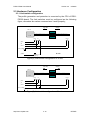
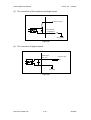
(2) The connection of pulse output
FVCC (5V)
330R
1
3
6
5
4
CW
OPEN COLLECTOR
330R
1
3
6
5
4
CCW
OPEN COLLECTOR
330R
1
3
6
5
4
SONX
OPEN COLLECTOR
COM
FGND
PISO-PS300
POWER DRIVER
Source type connection
http://www.icpdas.com
4-18
ICPDAS
PISO-PS300 User Manual
Version 4.0
05/2005
FVCC (5V)
330R
1
6
5
4
3
CW
OPEN COLLECTOR
330R
1
6
5
4
3
CCW
OPEN COLLECTOR
330R
1
6
5
4
3
SONX
OPEN COLLECTOR
FGND
PISO-PS300
POWER DRIVER
Sink type (open collector) connection
connect 6-7, if “Sink type”
JP1
1
2
3
4
6
7
8
Sink type (open collector hardware setting)
http://www.icpdas.com
4-19
ICPDAS
PISO-PS300 User Manual
Version 4.0
05/2005
(3) The connection of limit switches and digital inputs
SERVO-300 card
VEXT(12~24V)
limit switches
or digital input
EXT_GND
EXT_VCC
Figure(8)
(4) The connection of digital outputs
SERVO-300 card
digital output
VEXT(12~24V)
OP1~OP7
Loading
EXT_GND
Figure(9)
http://www.icpdas.com
4-20
ICPDAS
PISO-PS300 User Manual
Version 4.0
05/2005
(5) The connection of encoder
CN4
CN1
A+
AB+
BC+
C-
Encoder
1A+
1A1B+
1B1C+
1C5V
GND
5V
GND
Figure (10) Connection between encoder and PISO-PS300 card
CN1
CN4
Encoder
A+
B+
C+
1A+
1A1B+
1B1C+
1C5V
GND
5V
GND
open collector
type encoder
Figure (11) Connection of open-collector type encoder
http://www.icpdas.com
4-21
ICPDAS
PISO-PS300 User Manual
Version 4.0
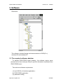
3. Software
05/2005
_
Directories
The software includes libraries and demonstrations of DOS(C++),
windows 95 and windows NT.
3.1 The required software skeleton
To operate PISO-PS300 board properly, the software require some
process and a timer interrupt (10ms) to get the information transferred from
PISO-PS300 board.
The minimum software requirements:
(1) load VXD file (if windows application)
(2) PISO-PS300 registration
(3) parameter setting
http://www.icpdas.com
4-22
ICPDAS
PISO-PS300 User Manual
Version 4.0
05/2005
(4) motion command
(5) release VXD file (if windows application)
(6) 10ms timer interrupt (mandatory)
MSTEP3_INITIAL();
(1). load VXD file
exist=MSTEP3_REGISTRATION(CARD1,address);
(2). registration
Select address and check
it is exist or not.
MSTEP3_RESET_SYSTEM(CARD1);
MSTEP3_SET_NC(CARD1,NO);
MSTEP3_SET_CONTROL_MODE(CARD1,x_mode,
y_mode, z_mode);
MSTEP3_SET_VAR(CARD1, DDA, AD, LSP, HSP,
arc_speed);
MSTEP3_SET_DEFDIR(CARD1, x_dir, y_dir, z_dir);
MSTEP3_SET_SERVO_ON(CARD1, x_son, y_son,
z_son);
(3) parameter setting
reset PISO-PS300 board
set normal close as NO
set control mode
set parameters of motion
profile
set direction
set servo on
(4) motion commands
MSTEP3_BACK_HOME(CARD1, X_axis, home_speed,
search_speed);
MSTEP3_PULSE_MOVE(CARD1, X_axis, 50000, 1000);
...
MSTEP3_RESET_SYSTEM(CARD1);
MSTEP3_END();
http://www.icpdas.com
4-23
reset PISO-PS300 board
(5) release VXD file
ICPDAS
PISO-PS300 User Manual
Version 4.0
void __fastcall TMSTEP::Timer1Timer(TObject *Sender)
{
char str[20];
Timer1->Interval = 10; //10ms
card1.ip = MSTEP3_DI(CARD1);
card1.msc= MSTEP3_MSC(CARD1);
if (card1.exist==YES)
{
MSTEP3_GET_CARD(CARD1);
card1.ls
=MSTEP3_GET_LIMIT(CARD1);
card1.p1 =MSTEP3_GET_P1(CARD1);
card1.XC =MSTEP3_GET_XC(CARD1);
card1.XP =MSTEP3_GET_XP(CARD1);
card1.YC =MSTEP3_GET_YC(CARD1);
card1.YP =MSTEP3_GET_YP(CARD1);
card1.ZC =MSTEP3_GET_ZC(CARD1);
card1.ZP =MSTEP3_GET_ZP(CARD1);
05/2005
(6) 10ms timer interrupt
(demonstration for BCB)
get digital input
get limit switches
get information from
PISO-PS300 board
get X axis command
get X axis position
get Y axis command
get Y axis position
get Z axis command
get Z axis position
}
}
http://www.icpdas.com
4-24
ICPDAS
PISO-PS300 User Manual
Version 4.0
05/2005
3.2 Functions
Constants
#define YES
1
#define NO
0
#define ON
1
#define OFF
0
#define CW_CCW 0
#define PULSE_DIR 1
#define NORMAL_DIR 0
#define REVERSE_DIR 1
#define FW
0
#define BW
1
#define CW
0
#define CCW 1
#define X_axis 1
#define Y_axis 2
#define Z_axis 3
#define XY_plane 1
#define XZ_plane 2
#define YZ_plane 3
#define READY 0
#define BUSY 1
#define DDA_CW_CCW
#define DDA_DIR_PULSE
#define SERVO_ON
#define DDA_EN
#define DDA_OE
0x00
0x01
0x02
0x04
0x08
#define ENC_MARK
#define ENC_AB_PHASE
#define ENC_CW_CCW
#define ENC_DIR_PULSE
#define ENC_EXTERNAL
#define ENC_INTERNAL
0x30
0x00
0x10
0x20
0x40
0x00
http://www.icpdas.com
4-25
ICPDAS
PISO-PS300 User Manual
Version 4.0
05/2005
3.2.1 Loading and unloading driver commands (only for
windows)
(1) MSTEP3_INITIAL( )
To load VxD driver.
(2) MSTEP3_END( )
To release VxD driver.
3.2.2 Setting commands
(3) unsigned char MSTEP3_REGISTRATION(unsigned char cardNo,
unsigned int address);
To select the hardware address of board and check it is exist or not.
The cardNo can be assign as 0~15 for the given address.
cardNo : card number 0~15.
address : select the address as well as hardware address on the board.
return NO : PISO-PS300 is not exist
YES : PISO-PS300 is exist
(4) MSTEP3_RESET_SYSTEM(unsigned char cardNo);
To reset PISO-PS300 board.
cardNo : card number 0~15.
(5) MSTEP3_SET_CONTROL_MODE(
unsigned char cardNo,
unsigned char x_mode,
unsigned char y_mode,
unsigned char z_mode);
To configure the output mode of DDA chip and the input mode of
encoder counter.
cardNo : card number 0~15.
x_mode : x axis control mode
y_mode : y axis control mode
z_mode : z axis control mode
control mode:
MSB 7
6
5
4
3
2
1
0 LSB
xx
EXT
ES1
ES0
OE
EN
xx
DDAM
http://www.icpdas.com
4-26
ICPDAS
PISO-PS300 User Manual
Version 4.0
05/2005
DDAM: set the output mode of DDA chip.
0: CW/CCW mode
1: DIR/PULSE mode
EN: enable or disable DDA
0: disable
1: enable
OE: set DDA output enable
0: disable output, for simulation mode.
1: enable output, for real mode.
ES1, ES0: set the input mode of the encoder counter.
00: AB phase mode
01: CW/CCW mode
10: DIR/PULSE mode
EXT: set the encoder counter input signal comes from external or
internal.
0: internal
1: external
If configure as internal mode, the output mode of DDA chip
should be the same as input mode of encoder counter, or you
will not count the pulse.
(6) MSTEP3_SET_VAR(
unsigned char cardNo,
unsigned char set_DDA_cycle,
unsigned char set_Acc_Dec,
unsigned int set_Low_Speed,
unsigned int set_High_Speed,
unsigned int set_arc_speed);
cardNo : card number 0~15.
set_DDA_cycle : software DDA cycle.
set_Acc_Dec : accelerating/decelerating speed.
set_Low_speed : set end speed.
set_High_speed : set maximum speed.
set_arc_speed : set curve speed.
High_Speed
Acc_Dec
http://www.icpdas.com
Acc_Dec
4-27
Low_Speed
ICPDAS
PISO-PS300 User Manual
Version 4.0
05/2005
Restriction:
1 ≤ DDA_ cycle ≤ 254
1 ≤ Acc _ Dec ≤ 200
1 ≤ Low _ Speed ≤ 200
Low _ Speed ≤ High _ Speed ≤ 2047
Arc _ Speed ≤ 2047
(7) MSTEP3_SET_DEFDIR(unsigned char cardNo,
unsigned char defdirX,
unsigned char defdirY,
unsigned char defdirZ);
Sometimes, the output direction of X-axis, Y-axis, Z-axis is not in
the desired direction due to motor connection or gear train. It is
recommended to unify the output direction as shown in Figure(4)(5)(6).
The CW/FW direction is defined as toward outside from motor and the
CCW/BW direction is defined as toward inside to motor.
cardNo : card number 0~15.
defdirX : X axis direction definition
defdirY : Y axis direction definition
defdirZ : Z axis direction definition
0 : NORMAL_DIR
1 : REVERSE_DIR
(8) MSTEP3_SET_SERVO_ON( unsigned char cardNo,
unsigned char sonX,
unsigned char sonY,
unsigned char sonZ);
cardNo : card number 0~15.
sonX, sonY, sonZ : to turn servo signal ON/OFF
0 : servo off
1 : servo on
(9) MSTEP3_SET_ZERO(unsigned char cardNo, unsigned char axis);
To set the position as zero in the PISO-PS300 card.
cardNo : card number 0~15.
http://www.icpdas.com
4-28
ICPDAS
PISO-PS300 User Manual
Version 4.0
05/2005
axis : X_axis, Y_axis or Z_axis.
(10) MSTEP3_PRESET_POSITION(unsigned char cardNo, unsigned
char axis, long preset_position);
To pre-set the position in the PISO-PS300 card.
cardNo : card number 0~15.
axis : X_axis, Y_axis or Z_axis.
preset_position : the desired pre-set position.
(11) MSTEP3_SET_NC(unsigned char cardNo, unsigned char sw);
To set limit switch as N.C. (normal close) mode or not.
cardNo : card number 0~15.
sw byte:
MSB 7
6
5
4
3
2
1
0 LSB
0
0
0
EMGSW
ZSW
YSW
XSW
ALLSW
ALLSW: if ALLSW=1, all limit switches XLS+, XLS-, XI, YLS+, YLS-, YI,
ZLS+, ZLS-, ZI, EMG are in N.C.(normal close) mode.
XSW: if XSW=1 and ALLSW=0, limit switches XLS+, XLS-, XI are in
N.C. (normal close) mode.
YSW: if YSW=1 and ALLSW=0, limit switches YLS+, YLS-, YI are in
N.C. (normal close) mode.
ZSW: if ZSW=1 and ALLSW=0, limit switches ZLS+, ZLS-, ZI are in
N.C. (normal close) mode.
EMGSW: if EMGSW=1 and ALLSW=0, limit switch EMG is in N.C.
(normal close) mode.
3.2.3 Stop Commands
(12) MSTEP3_STOP(unsigned char cardNo, unsigned char axis);
To stop the motion command of selected axis
cardNo : card number 0~15.
axis : selected axis
(13) MSTEP3_DEC_STOP(unsigned char cardNo, unsigned char axis);
Decelerating to stop the selected axis’s motor.
cardNo : card number 0~15.
axis : selected axis
http://www.icpdas.com
4-29
ICPDAS
PISO-PS300 User Manual
Version 4.0
05/2005
(14) MSTEP3_STOP_ALL(unsigned char cardNo);
To stop motion command immediately, this function is the same as
emergency stop by hardware EMG switch.
cardNo : card number 0~15.
This command will clear all of pending commands in the buffer, and
immediately terminate all commands which is executing in PISO-PS300
board.
(15) MSTEP3_EMG_STOP(unsigned char cardNo);
This function is the same as MSTEP3_STOP_ALL(), but MSTEP2_
EMG_STOP() only can be used in timer interrupt routine.
cardNo : card number 0~15.
This command will clear all of pending commands in the buffer, and
immediately terminate all commands which is executing in PISO-PS300
board.
Example:
void interrupt sampling_ISR(...) // 10ms sample once
{
disable();
.
.
.
//----- check F7 -----------------------------if ((chkey=bioskey(1))!=0) //don't get key
if (chkey==0x4100)
{
bioskey(0); //get key
MSTEP3_EMG_STOP(CARD1);
}
.
.
.
outportb(0x20,0x20);
enable();
}
http://www.icpdas.com
4-30
ICPDAS
PISO-PS300 User Manual
Version 4.0
05/2005
3.2.4 Motion commands
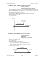
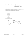
(16) MSTEP3_BACK_HOME(
unsigned char cardNo,
unsigned char axis,
unsigned char set_home_speed,
unsigned char set_search_speed);
This command is used to move the motor toward CCW/BW direction at
home speed and then stop when home index switch /XI (/YI) (/ZI) is
touched. And then the motor will move toward CW/FW direction at
search speed to find absolute zero. When /XI=1 and C=0, the motor stop
and set position to zero. In general, the search speed should be set to
2~5. If the search speed is too large, the absolute point might be lost. If
search speed is set too small, it spends a lot of time.
cardNo : card number 0~15.
axis : selected axis.
0 < set_home_speed < 50
0 < set_search speed < 10
Speed
home index
/XI (/YI) (/ZI)
home speed
"+"
CCW/BW direction
"-"
search speed
encoder index C
http://www.icpdas.com
4-31
ICPDAS
PISO-PS300 User Manual
Version 4.0
05/2005
(17) MSTEP3_BACK_HOME01( unsigned char cardNo,
unsigned char axis,
unsigned char set_home_speed);
This command is used to move the motor toward CCW/BW direction at
home speed and then stop when home index switch /XI (/YI) (/ZI) is
touched, then set the position to zero.
This command is special for stepping motor without the encoder.
cardNo : card number 0~15.
axis : selected axis.
Speed
Home index
/XI (/YI) (/ZI)
Home speed
“+”
CCW/BW direction
“-”
(18) MSTEP3_PULSE_MOVE(unsigned char cardNo,
unsigned char axis,
long pulseN,
unsigned int move_speed);
cardNo : card number 0~15.
axis : selected axis.
pulseN : the distance to be moved.
when pulseN>0, move toward CW/FW direction
when pulseN<0, move toward CCW/BW direction
0 < move_speed <= 2040
move speed
Acc_Dec
Acc_Dec
pulseN
http://www.icpdas.com
4-32
ICPDAS
PISO-PS300 User Manual
Version 4.0
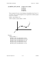
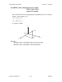
(19) MSTEP3_INTP_PULSE(
05/2005
unsigned char cardNo,
int Xpulse,
int Ypulse,
int Zpulse);
This command will move a short distance (interpolation short line) in XY-Z space. This command supports user to generate an arbitrary space
curve in X-Y-Z space.
cardNo : card number 0~15.
-2040 <= Xpulse, Ypulse, Zpulse <= 2040
Y
10
9
2
3
4
5
8
6
7
1
(Xpulse,Ypulse,Zpulse)
X
Z
Example:
#define CARD1 1
MSTEP3_INTP_PULSE(CARD1,20,20,2);
MSTEP3_INTP_PULSE(CARD1,20,13,10);
MSTEP3_INTP_PULSE(CARD1,20,7,10);
MSTEP3_INTP_PULSE(CARD1,20,0,5);
MSTEP3_INTP_PULSE(CARD1,15,-5,5);
http://www.icpdas.com
4-33
ICPDAS
PISO-PS300 User Manual
Version 4.0
05/2005
(20) MSTEP3_CONSTANT_SPEED(unsigned char cardNo,
unsigned char axis,
unsigned char dir,
unsigned int move_speed);
This command will accelerate or decelerate the selected axis’s motor to
the “move_speed”. The rotating motor can be stop by the command
MSTEP3_STOP() or MSTEP3_DEC_STOP(). This command can be
continuously input to SERVO300 card to change speed.
cardNo : card number 0~15.
axis : selected axis.
1 : X axis
2 : Y axis
3 : Z axis
dir : moving direction.
0 : CW
1 : CCW
0 < move_speed <= 2040
speed
command
command
command
http://www.icpdas.com
4-34
ICPDAS
PISO-PS300 User Manual
Version 4.0
05/2005
(21) MSTEP3_INTP_XYZ(unsigned char cardNo,
long x, long y, long z,
unsigned int speed);
This command will move a long distance interpolation line in X-Y-Z plane.
cardNo : card number 0~15.
− 2 31 + 1 ≤ # x ≤ 2 31 − 1
− 2 31 + 1 ≤ # y ≤ 2 31 − 1
− 2 31 + 1 ≤ # z ≤ 2 31 − 1
0 < speed <= 2040
Y
(x,y,z)
(0,0,0)
X
Z
Example:
MSTEP3_INTP_XYZ(CARD1,2000,-3000,3333,1000);
MSTEP3_INTP_XYZ(CARD1,-500,200,200,500);
http://www.icpdas.com
4-35
ICPDAS
PISO-PS300 User Manual
Version 4.0
05/2005
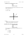
(22) MSTEP3_INTP_LINE(unsigned char cardNo,
long x,
long y,
unsigned int speed);
This command will move a long distance interpolation line in X-Y plane.
cardNo : card number 0~15.
− 2 31 + 1 ≤ # x ≤ 2 31 − 1
− 2 31 + 1 ≤ # y ≤ 2 31 − 1
0 < speed <= 2040
Y
(X,Y)
(0,0)
X
Example:
MSTEP3_INTP_LINE(CARD1,2000,-3000,1000);
MSTEP3_INTP_LINE(CARD1,-500,200,1000);
(23) MSTEP3_INTP_LINE01(unsigned char cardNo,
unsigned char plane,
long x,
long y,
unsigned int speed);
This command will move a long distance interpolation line in X-Y or
X-Z or Y-Z plane.
plane :
1 : X-Y plane
2 : X-Z plane
3 : Y-Z plane
http://www.icpdas.com
4-36
ICPDAS
PISO-PS300 User Manual
Version 4.0
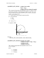
(24) MSTEP3_INTP_CIRCLE(
05/2005
unsigned char cardNo,
long x, long y,
unsigned char dir, unsigned int speed);
This command will generate an interpolation circle in X-Y plane. PC will
automatically generate a trapezoidal speed profile of X-axis and Y-axis,
and send these profile by way of MSTEP3_INTP_PULSE( ) command.
cardNo : card number 0~15.
x, y : center point of circle related to present position.
dir : moving direction.
0 : CW
1 : CCW
− 2 31 + 1 ≤ # x ≤ 2 31 − 1
− 2 31 + 1 ≤ # y ≤ 2 31 − 1
0 < speed <= 2040
Y
(X,Y)
CW
X
CCW
where radius = sqrt(X^2 + Y^2)
Example:
MSTEP3_INTP_CIRCLE(CARD1, 2000,-2000,CW,500);
(25) MSTEP3_INTP_CIRCLE01(unsigned char cardNo,
unsigned char plane, long x, long y,
unsigned char dir,
unsigned int speed);
This command will generate an interpolation circle in X-Y or
X-Z or Y-Z plane.
plane :
1 : X-Y plane
2 : X-Z plane
3 : Y-Z plane
http://www.icpdas.com
4-37
ICPDAS
PISO-PS300 User Manual
Version 4.0
05/2005
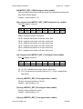
(26) MSTEP3_INTP_ARC(unsigned char cardNo,
long x, long y, long R,
unsigned char dir, unsigned int speed);
This command will generate an interpolation arc in X-Y plane. PC will
automatically generate a trapezoidal speed profile of X-axis and Y-axis,
and send these profile by way of MSTEP3_INTP_PULSE( ) command.
cardNo : card number 0~15.
x, y : end point of arc related to present position.
R : radius of arc.
if R>0 , the arc < 180 degree
if R<0 , the arc > 180 degree
dir : moving direction.
0 : CW
1 : CCW
R
dir
path of curve
R>0
CW
'B'
R>0
CCW
'C'
R<0
CW
'A'
R<0
CCW
'D'
0 < speed <= 2040
'A'
CW
Y
(X,Y)
'B'
CW
'C'
CCW
'D'
X
CCW
http://www.icpdas.com
4-38
ICPDAS
PISO-PS300 User Manual
Version 4.0
05/2005
Restriction:
− 2 31 + 1 ≤ # x ≤ 2 31 − 1
− 2 31 + 1 ≤ # y ≤ 2 31 − 1
−2 31 + 1 ≤ # R ≤ 2 31 − 1
R≥
x2 + y2
2
Example:
MSTEP3_INTP_ARC(CARD1,2000,-2000,2000,CW,500);
(27) MSTEP3_INTP_ARC01(unsigned char cardNo,
unsigned char plane, long x, long y,
long R, unsigned char dir,
unsigned int speed);
This command will generate an interpolation arc in X-Y or X-Z or Y-Z
plane.
plane :
1 : X-Y plane
2 : X-Z plane
3 : Y-Z plane
http://www.icpdas.com
4-39
ICPDAS
PISO-PS300 User Manual
Version 4.0
05/2005
3.2.5 Get information
To get the information transferred from PISO-PS300 board, the user
should construct a timer interrupt to poll information. The software
skeleton has been described in chapter 3.1.
The MSTEP3_GET_CARD() command should be executed at the
beginning and then to get information you need.
example:
void __fastcall TMSTEP::Timer1Timer(TObject *Sender)
{
char str[20];
Timer1->Interval = 10; //10ms
if (card1.exist==YES)
{
card1.ip = MSTEP3_DI(CARD1);
card1.msc= MSTEP3_MSC(CARD1);
MSTEP3_GET_CARD(CARD1);
card1.ls =MSTEP3_GET_LIMIT(CARD1);
card1.p1 =MSTEP3_GET_P1(CARD1);
card1.XC =MSTEP3_GET_XC(CARD1);
card1.XP =MSTEP3_GET_XP(CARD1);
card1.YC =MSTEP3_GET_YC(CARD1);
card1.YP =MSTEP3_GET_YP(CARD1);
card1.ZC =MSTEP3_GET_ZC(CARD1);
card1.ZP =MSTEP3_GET_ZP(CARD1);
}
}
http://www.icpdas.com
4-40
ICPDAS
PISO-PS300 User Manual
Version 4.0
05/2005
(28) MSTEP3_GET_CARD(unsigned char cardNo)
This command uses timer interrupt to poll the information transferred
from PISO-PS300 board.
CardNo : card number 0~15.
(29) unsigned char MSTEP3_GET_LIMIT(unsigned char cardNo)
The limit register contains
MSB 7
6
xx
/EMG
5
4
3
2
1
0 LSB
/ZLS- /ZLS+ /YLS- /YLS+ /XLS- /XLS+
/EMG: emergency input, low active.
/XLS+: positive limit switch of X axis, active low.
/XLS-: negative limit switch of X axis, active low.
/YLS+: positive limit switch of Y axis, active low.
/YLS-: negative limit switch of Y axis, active low.
/ZLS+: positive limit switch of Z axis, active low.
/ZLS-: negative limit switch of Z axis, active low.
(30) unsigned char MSTEP3_GET_P1(unsigned char cardNo)
The P1 register contains
MSB 7
6
5
4
3
2
1
0 LSB
xx
C3
C2
C1
/ZI
/YI
/XI
xx
/XI, /YI, /ZI : indicate home index switch, active low.
C1, C2, C3 indicate the encoder index of X, Y, Z axis, respectively.
high active
(31) long MSTEP3_GET_XC(unsigned char cardNo)
Get the command position of X axis.
CardNo : card number 0~15.
(32) long MSTEP3_GET_XP(unsigned char cardNo)
Get the actual position of X axis.
CardNo : card number 0~15.
(33) long MSTEP3_GET_YC(unsigned char cardNo)
http://www.icpdas.com
4-41
ICPDAS
PISO-PS300 User Manual
Version 4.0
05/2005
Get the command position of Y axis .
CardNo : card number 0~15.
(34) long MSTEP3_GET_YP(unsigned char cardNo)
Get the actual position of Y axis .
CardNo : card number 0~15.
(35) long MSTEP3_GET_ZC(unsigned char cardNo)
Get the command position of Z axis.
CardNo : card number 0~15.
(36) long MSTEP3_GET_ZP(unsigned char cardNo)
Get the actual position of Z axis
CardNo : card number 0~15.
http://www.icpdas.com
4-42
ICPDAS
PISO-PS300 User Manual
Version 4.0
05/2005
3.2.6 Others
(37) unsigned char MSTEP3_DI(unsigned char cardNo)
To get the DI register
MSB 7
6
5
4
3
2
1
0 LSB
di7
di6
di5
di4
di3
di2
di1
di0
(38) MSTEP3_DO(unsigned char cardNo, unsigned char value)
To output DO port
MSB 7
6
5
4
3
2
1
0 LSB
don't
use
DO6
DO5
DO4
DO3
DO2
DO1
DO0
(39) unsigned char MSTEP3_MSC(unsigned char cardNo)
To get the status of limit switch
MSB 7
6
5
4
/EMG /Zstop /Ystop /Xstop
3
2
1
0 LSB
xx
xx
xx
xx
/Xstop, /Ystop, /Zstop : indicates which axis is stop, low active
/EMG : emergency switch, low active.
(40) MSTEP3_WAIT_X(unsigned char cardNo)
To wait X-axis goes to the STOP state.
(41) MSTEP3_WAIT_Y(unsigned char cardNo)
To wait Y-axis goes to the STOP state.
(42) MSTEP3_WAIT_Z(unsigned char cardNo)
To wait Z-axis goes to the STOP state.
(43) unsigned char MSTEP3_IS_X_STOP(unsigned char cardNo)
To check whether X axis is STOP or not.
Return value
0 (NO) : not yet stop
1 (YES) : stop
(44) unsigned char MSTEP3_IS_Y_STOP(unsigned char cardNo)
To check whether Y axis is STOP or not.
http://www.icpdas.com
4-43
ICPDAS
PISO-PS300 User Manual
Return value
Version 4.0
05/2005
0 (NO) : not yet stop
1 (YES) : stop
(45) unsigned char MSTEP3_IS_Z_STOP(unsigned char cardNo)
To check whether Z axis is STOP or not.
Return value
0 (NO) : not yet stop
1 (YES) : stop
http://www.icpdas.com
4-44
ICPDAS
PISO-PS300 User Manual
Version 4.0
05/2005
3.2.7 New Interpolation command
The new driver provide a set of state-machine-type interpolation command
including:
(46) MSTEP3_INTP_XYZ02(unsigned char cardNo,
long x, long y, long z,
unsigned int speed,
unsigned char acc_mode);
(47) MSTEP3_INTP_LINE02(unsigned char cardNo,
unsigned char plane,
long x,
long y,
unsigned int speed,
unsigned char acc_mode);
(48) MSTEP3_INTP_CIRCLE02(unsigned char cardNo,
unsigned char plane,
long x, long y,
unsigned char dir,
unsigned int speed,
unsigned char acc_mode);
(49) MSTEP3_INTP_ARC02(unsigned char cardNo,
unsigned char plane,
long x, long y, long R,
unsigned char dir,
unsigned int speed,
unsigned char acc_mode);
acc_mode: 0: enable acceleration and deceleration profile
1: disable acceleration and deceleration profile
These command can be set acc_mode=1 to disable the acceleration and
deceleration profile.
(50) unsigned char MSTEP3_INTP_STOP()
These command is to compute the interpolation service. It will return
READY(0) for interpolation command completed. And retrun BUSY(1)
for not yet complete.
(51) void MSTEP3_INTP_ONLINE_SETSPEED(unsigned int speed)
User can use this command to dynamicly set the interpolation moving
speed when interpolation command(XYZ02, LINE02, CIRCLE02, ARC02)
is running.
where, 0< speed < 2040
http://www.icpdas.com
4-45
ICPDAS
PISO-PS300 User Manual
Version 4.0
05/2005
These 4 commands are state machine type command, they are only set
parameters into the driver. The computing entity is in MSTEP3_GET_CARD()
(only for windows) and MSTEP3_INTP_STOP().
In windows application, when The MSTEP3_GET_CARD() command is
running in the timer interrupt routine by 10ms, it will help to calculate the
interpolation service.
Both of DOS and windows application, User can directly call the do {} while
(MSTEP3_INTP_STOP()!=READY) to execute the computing entity. The user
can monitor something or waiting for keyboard input in the do loop. Therefore,
The user has chance to do the software stop or monitor something.
DOS application example1
MSTEP3_INTP_XYZ02(CARD1,1000,1000,0,20,1);
do
{
show_panel();
if (kbhit()) chkey=bioskey(0); //F7=0x4100
} while ( (chkey!= 0x4100) && (MSTEP3_INTP_STOP()!=READY) );
if (chkey==0x4100) MSTEP3_STOP_ALL(CARD1);
DOS application example2
void TimerInterrupt(void)
{
MSTEP3_GET_CARD(CARD1);
show_panel();
if (kbhit())
chkey=bioskey(0); //F7=0x4100
}
void test_intp(void)
{
MSTEP3_INTP_XYZ02(CARD1,1000,1000,0,20,1);
do
{ } while ( (chkey!= 0x4100) && (MSTEP3_INTP_STOP()!=READY) );
if (chkey==0x4100) MSTEP3_STOP_ALL(CARD1);
}
Windows application example1
void __fastcall TMSTEP::Timer1Timer(TObject *Sender)
http://www.icpdas.com
4-46
ICPDAS
PISO-PS300 User Manual
Version 4.0
05/2005
{
Timer1->Interval = 10; //10ms
MSTEP3_GET_CARD(CARD1);
show_panel();
}
void __fastcall TMSTEP::IntpLineClick(TObject *Sender)
{
char str[20];
if (
(MSTEP3_IS_X_STOP(CARD1)==NO)
|| (MSTEP3_IS_Y_STOP(CARD1)==NO)
|| (MSTEP3_IS_Z_STOP(CARD1)==NO))
{
Application->MessageBox(
"Motor's rotating, can't execute this command",
"Message Box",
MB_DEFBUTTON1);
return;
};
ltoa(x, str, 10);
IntpLineDialog->Xpulse->Text = AnsiString(str);
ltoa(y, str, 10);
IntpLineDialog->Ypulse->Text = AnsiString(str);
ltoa(speed, str, 10);
IntpLineDialog->speed->Text = AnsiString(str);
IntpLineDialog->SelectPlane->ItemIndex = plane-1;
if (IntpLineDialog->ShowModal()==mrOk)
{
x= (long)IntpLineDialog->Xpulse->Text.ToInt();
y= (long)IntpLineDialog->Ypulse->Text.ToInt();
speed= (unsigned int)IntpLineDialog->speed->Text.ToInt();
plane= (unsigned char)(IntpLineDialog->SelectPlane->ItemIndex + 1);
//MSTEP3_INTP_LINE01(CARD1,plane,x,y,speed);
MSTEP3_INTP_LINE02(CARD1,plane,x,y,speed,0);
do {Application->ProcessMessages();}
while (MSTEP3_INTP_STOP()!=READY);
http://www.icpdas.com
4-47
ICPDAS
PISO-PS300 User Manual
Version 4.0
05/2005
}
}
http://www.icpdas.com
4-48
ICPDAS
PISO-PS300 User Manual
Version 4.0
05/2005
The example for wait stop command (DOS):
//test XYZ01, no acceleration
MSTEP3_INTP_XYZ02(CARD1,1000,1000,0,20,1);
do {} while (MSTEP3_INTP_STOP()!=READY);
MSTEP3_INTP_XYZ02(CARD1,2000,1000,0,22,1);
do {} while (MSTEP3_INTP_STOP()!=READY);
MSTEP3_INTP_XYZ02(CARD1,2000,2000,0,24,1);
do {} while (MSTEP3_INTP_STOP()!=READY);
MSTEP3_INTP_XYZ02(CARD1,1000,2000,0,26,1);
do {} while (MSTEP3_INTP_STOP()!=READY);
do {} while (MSTEP3_IS_X_STOP(CARD1)==NO);
delay(10000);
//test WAIT_X, WAIT_Y, WAIT_Z
MSTEP3_INTP_LINE02(CARD1, XY_plane, 10000,-10000,200,0);
do {} while (MSTEP3_INTP_STOP()!=READY);
MSTEP3_INTP_LINE02(CARD1, XY_plane, -10000, 10000,200,0);
do {} while (MSTEP3_INTP_STOP()!=READY);
MSTEP3_INTP_XYZ02(CARD1, 5000, -10000, -40000, 200, 0);
do {} while (MSTEP3_INTP_STOP()!=READY);
do {} while (MSTEP3_IS_X_STOP(CARD1)==NO);
do {} while (MSTEP3_IS_Y_STOP(CARD1)==NO);
do {} while (MSTEP3_IS_Z_STOP(CARD1)==NO);
MSTEP3_STOP_ALL(CARD1);
delay(10000);
MSTEP3_INTP_CIRCLE02(CARD1, XY_plane, 5000,-5000, CW, 200, 0);
do {} while (MSTEP3_INTP_STOP()!=READY);
do {} while (MSTEP3_IS_X_STOP(CARD1)==NO);
do {} while (MSTEP3_IS_Y_STOP(CARD1)==NO);
MSTEP3_STOP_ALL(CARD1);
http://www.icpdas.com
4-49
ICPDAS
PISO-PS300 User Manual
Version 4.0
4. Driver
05/2005
_
DOS Driver (C, C++)
Item
File
Header file
MSTEP3.h
Library file
MSTEP3.lib
Example file
Sp3tcc.prj (turbo C++)
Sp3bcc.ide (borland C++)
Windows 95 Driver
Item
File
Header file
Mstep32.h
ImportLibrary file
Mstep32.lib
Bcstep32.lib (only for Borland C++)
Dynamic Link Library
Mstep32.dll(copy to c:\windows)
VxD file
Napdio.vxd(copy to c:\windows)
Example file
Bcmstep3.bpr(Borland C++ Builder)
Bcmstep3.cpp
main.cpp
Windows NT Driver
Item
File
Header file
Mstep32.h
ImportLibrary file
Mstep32.lib
Bcstep32.lib (only for Borland C++)
Dynamic Link Library
Mstep32.dll(copy to c:\windows)
Driver
regdrv.bat
napwnt.ini
napwnt.sys
regini.exe
Example file
Bcmstep3.bpr(Borland C++ Builder)
Bcmstep3.cpp
main.cpp
http://www.icpdas.com
4-50
ICPDAS
PISO-PS300 User Manual
Version 4.0
05/2005
_
5. Example
5.1 DOS example
The execution file, SP3TCC.EXE/SP3BCC.EXE, is a testing program. It
can let you fully understand the action of every command. The source files
include SP3TCC.PRJ(SP3BCC.IDE), MAIN.CPP, MSTEP3.H and
MSTEP3.LIB. The MAIN.CPP file provides several examples of MSTEP3
command set. If you have any questions about the command set, you can
trace the MAIN.CPP source file.
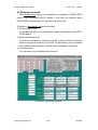
The panel of SP3TCC.EXE has three areas :
(1) I/O information area
It indicates the status of limit switch, digital input/output and PISOPS300 board.
(2) motion parameter area
It shows the variables of motion parameter. It also shows the command
position and actual position of each axis.
(3) Command area
You can select any command and execute it.
The panel of DOS example
http://www.icpdas.com
4-51
ICPDAS
PISO-PS300 User Manual
Version 4.0
05/2005
5.2 Windows example
The bcmstep3.exe (source file included) is an example of PISO-PS300
board. It has windows95 and NT edition. If you have any question about
PISO-PS300 command set, you can trace the source file.
The panel of bcmstep3.exe has three areas :
(1) I/O information area
It indicates the status of limit switches, digital inputs/outputs and PISOPS300 board.
(2) Motion parameter area
It shows the variables of motion parameter. It also shows the command
position and actual position of each axis. All parameters can be modified
and updated by pressing the “Update Servo Parameters” menu bar.
(3) Command area
You can select any command and execute it.
The panel of windows example
http://www.icpdas.com
4-52
ICPDAS
PISO-PS300 User Manual
Version 4.0
05/2005
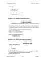
6. Application
_
The PISO-PS300 can be applied in X-Y table control, robot, CNC PCB
driller, CNC PCB router, CNC wire cutter, lathe and semiconductor
equipment.
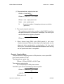
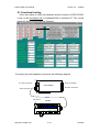
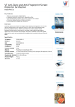
For easily set up a machine, there is a daughter board DB-8R can be
adopted. The DB-8R board is the connection board for limit switches, digital
inputs/outputs.
IP8 IP7 IP6 IP5 IP4 IP3 IP2 IP1 EMG YI
XI YLS-YLS+XLS-XLS+
DIP switch for test
limit switch and inputs
DB-25
ACOM
VCOM
VI
DP8 DP7 DP6 DP5 DP4 DP3 DP2 DP1
The DB-8R daughter board
http://www.icpdas.com
4-53
ICPDAS
PISO-PS300 User Manual
Version 4.0
05/2005
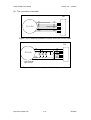
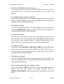
6.1 Functional testing
If the user wants to verify the hardware and the function of PISO-PS300,
it can run the bcmstep3.exe in windows95/98 or windows NT. The control
panel will show in the screen as following.
For easily test, the hardware connect as the following diagram.
Z axis connection
X,Y axis connection
PISO-PS300
Encoder connection
DIO connection
DIP switch
DB-8R
24V
http://www.icpdas.com
4-54
ICPDAS
PISO-PS300 User Manual
Version 4.0
05/2005
• Check the PISO-PS300 card is exist or not
The indicator “EXIST” will show the PISO-PS300 card is exist or not. In
case of the card is not exist, all of the function will not be able to be
perform.
• Test digital inputs and limit switches
First of all, the external power +24V shall be applied. While turn on the DIP
switch on DB-8R daughter board, the corresponding LED on DB-8R and
indicator in the control panel will turn on.
• Test digital outputs
First of all, the external power +24V shall be applied. The user can press
the button MSTEP3_DO, and turn on the DO then press OK button, the
corresponding DO LED on DB-8R will light.
• Test encoder input
The user can use a encoder or servo motor to test this item. It just connect
the A+,A-,B+,B-,C+,C-,5V and GND to the PISO-PS300, and then rotate
the encoder or motor’s shaft by manual. The position will be shown on the
panel. The index C also will be shown on panel when rotate slowly.
• Test pulse output
Using the command MSTEP3_CONSTANT_SPEED, the PISO-PS300 will
outputs the pulses on the pins CW_PULSE1 and CCW_DIR1. User can
use these pin to drive the stepping motor or servo motor. User also can
use logic probe or scope to check it.
• Test servo on signal
The servo ON/OFF switch right in the parameter area on the panel. The
user can select ON or OFF, and press the update parameter button, the
corresponding SON will act.
• Test motion command in simulation mode
First of all, select the SIMU mode and then press the update parameter
button. The user can execute the motion command such as
MSTEP3_PULSE_MOVE. The simulated position will show on the control
panel.
http://www.icpdas.com
4-55
ICPDAS
PISO-PS300 User Manual
Version 4.0
05/2005
6.2 Hand wheel input
//------------------------------------------------------------------------------------------------// DEMO1.cpp
12/11/99
//
// Function:
// hand wheel(encoder) input from Z axis,
// then move X axis
//-----------------------------------------------------------------------------------------------#include <math.h>
#include <stdio.h>
#include <stdlib.h>
#include <conio.h>
#include <dos.h>
#include <bios.h>
#include "mstep3.h"
//----- define -------------------------------------------#define CARD1 0
//----- structure ----------------------------------------typedef struct
{
//---- parameter --------unsigned int address;
unsigned char exist;
unsigned char DDA;
unsigned char AD;
unsigned int LSP;
unsigned int HSP;
unsigned char home_speed;
unsigned char search_speed;
unsigned int arc_speed;
unsigned char x_mode;
unsigned char x_dir;
unsigned char x_son;
unsigned char y_mode;
unsigned char y_dir;
http://www.icpdas.com
4-56
ICPDAS
PISO-PS300 User Manual
Version 4.0
05/2005
unsigned char y_son;
unsigned char z_mode;
unsigned char z_dir;
unsigned char z_son;
//---- information ------unsigned char op;
unsigned char ip;
unsigned char msc;
unsigned char ls;
unsigned char p1;
unsigned char x_state;
unsigned char y_state;
unsigned char z_state;
long
XC;
long
XP;
long
YC;
long
YP;
long
ZC;
long
ZP;
}CardParameter;
//----- variable -----------------------------------------CardParameter card1;
long new_z,old_z;
char GetPosition;
//-------------------------------------------------------------------#define INTR 0x08
//timer interrupt number
#define sampling_time 2982
//<1193180Hz>/2982=Hz(2.5ms)
unsigned long sampling_counter1=0;
void interrupt sampling_ISR(...);
void interrupt (*old_handler)(...);
//-------------------------------------------------------------------// set timer interrupt period as 2.5ms,
// and set the vector of INTR=0x08 as user's program address
//-------------------------------------------------------------------http://www.icpdas.com
4-57
ICPDAS
PISO-PS300 User Manual
Version 4.0
05/2005
void set_timer()
{
disable();
old_handler = getvect(INTR);
setvect(INTR, sampling_ISR);
outp(0x43, 0x34);
//modify timer
outp(0x40, sampling_time & 0x00ff);
outp(0x40, (sampling_time >> 8) );
outportb(0x20,0x20);
enable();
}
//-------------------------------------------------------------------// recover the vector of INTR=0x08,
// reset the timer
//-------------------------------------------------------------------void release_timer()
{
disable();
outp(0x43, 0x34);
outp(0x40, 0x00);
outp(0x40, 0x00);
setvect(INTR, old_handler);
outportb(0x20,0x20);
enable();
}
//-------------------------------------------------------------------// Timer interrupt
// 1. trigger the original vector of INTR=0x08 by 18.Hz
// 2. get the PISO-PS300 information and status
//-------------------------------------------------------------------void interrupt sampling_ISR(...) // 2.5ms sample once
{
disable();
sampling_counter1 += sampling_time;
if (sampling_counter1>65536L)
{
sampling_counter1-=65536L;
old_handler();
//trigger original 0x08h (18.Hz)
http://www.icpdas.com
4-58
ICPDAS
PISO-PS300 User Manual
Version 4.0
05/2005
};
//----- get card 1 information ---------------if (card1.exist==YES)
{
card1.ip = MSTEP3_DI(CARD1);
card1.msc = MSTEP3_MSC(CARD1);
MSTEP3_GET_CARD(CARD1);
card1.ls =MSTEP3_GET_LIMIT(CARD1);
card1.p1 =MSTEP3_GET_P1(CARD1);
card1.XC =MSTEP3_GET_XC(CARD1);
card1.XP =MSTEP3_GET_XP(CARD1);
card1.YC =MSTEP3_GET_YC(CARD1);
card1.YP =MSTEP3_GET_YP(CARD1);
card1.ZC =MSTEP3_GET_ZC(CARD1);
card1.ZP =MSTEP3_GET_ZP(CARD1);
}
GetPosition=1;
outportb(0x20,0x20);
enable();
}
//-------------------------------------------------------------------// set the operation parameter of PISO-PS300
//-------------------------------------------------------------------void set_parameter()
{
MSTEP3_SET_NC(CARD1,NO);
MSTEP3_SET_CONTROL_MODE(CARD1, card1.x_mode,
card1.y_mode, card1.z_mode);
MSTEP3_SET_VAR(CARD1, card1.DDA, card1.AD, card1.LSP,
card1.HSP, card1.arc_speed);
MSTEP3_SET_DEFDIR(CARD1, card1.x_dir, card1.y_dir, card1.z_dir);
MSTEP3_SET_SERVO_ON(CARD1, card1.x_son, card1.y_son,
card1.z_son);
}
//#########################################################
http://www.icpdas.com
4-59
ICPDAS
PISO-PS300 User Manual
Version 4.0
05/2005
void main()
{
char ch;
disable();
clrscr();
//------set card 1 parameters------------------------------------card1.address
= 0; //0~15
card1.DDA
= 10;
card1.AD
= 5;
card1.LSP
= 5;
card1.HSP
= 150;
card1.home_speed = 10;
card1.search_speed = 2;
card1.arc_speed
= 50;
card1.x_mode
card1.x_dir
card1.x_son
card1.y_mode
card1.y_dir
card1.y_son
card1.z_mode
card1.z_dir
card1.z_son
= DDA_CW_CCW|DDA_EN|DDA_OE|
ENC_AB_PHASE|ENC_EXTERNAL;
= NORMAL_DIR;
= ON;
= DDA_CW_CCW|DDA_EN|DDA_OE|
ENC_AB_PHASE|ENC_EXTERNAL;
= NORMAL_DIR;
= OFF;
= DDA_CW_CCW|DDA_EN|DDA_OE|
ENC_AB_PHASE|ENC_EXTERNAL;
= NORMAL_DIR;
= OFF;
//---- check PISO-PS300/S300 is exist or not -----------------------card1.exist=MSTEP3_REGISTRATION(CARD1, card1.address);
if (card1.exist!=YES)
{
cprintf("There is not exist any PISO-PS300/S300 card !");
return;
}
MSTEP3_RESET_SYSTEM(CARD1);
http://www.icpdas.com
4-60
ICPDAS
PISO-PS300 User Manual
Version 4.0
05/2005
clrscr();
//------------------------------------------------------------------set_timer();
set_parameter();
enable();
GetPosition=0;
do {} while (GetPosition=0);
new_z=card1.ZP;
old_z=new_z;
do{
card1.msc=MSTEP3_MSC(CARD1);
//get msc register
if ((card1.msc & 0x01)== 0x00) //check FIFO1 is empty or not!
{
new_z=card1.ZP;
//output the difference of Z-axis to X-axis
MSTEP3_INTP_PULSE(CARD1,new_z-old_z,0,0);
old_z=new_z;
}
gotoxy(1,10);
cprintf("HandWheel Z=%10ld, X output=%10ld", new_z, card1.XC);
} while (bioskey(1)==0);
MSTEP3_RESET_SYSTEM(CARD1);
release_timer();
}
http://www.icpdas.com
4-61
ICPDAS
PISO-PS300 User Manual
Version 4.0
05/2005
7. PISO-PS300 new function
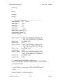
1. (6/23/2002) When using sink type (open collector) connection, please
connect JP1-6, JP1-7. This modification can make CW, CCW, SONX are
initial “high” to suit “open collector connection” at power driver side.
FVCC (5V)
330R
1
6
5
4
3
CW
OPEN COLLECTOR
330R
1
6
5
4
3
CCW
OPEN COLLECTOR
330R
1
6
5
4
3
SONX
OPEN COLLECTOR
FGND
PISO-PS300
POWER DRIVER
Sink type (open collector) connection
connect 6-7, if “Sink type”
JP1
1
2
3
4
6
7
8
Sink type (open collector hardware setting)
http://www.icpdas.com
4-62
ICPDAS