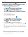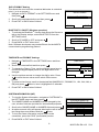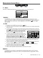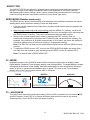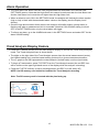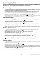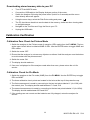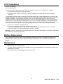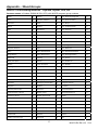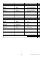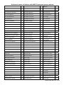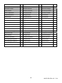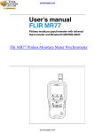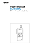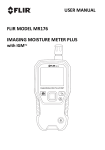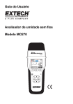
1
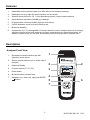
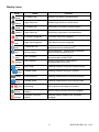
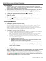
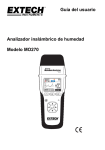
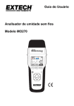
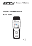
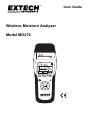
User Guide Wireless Moisture Analyzer Model MO270 05-12-2012 03:32:48 10.0 80.0 68.2 54.2 20.9 MENU Table of Contents Introduction .............................................................................................................................................. 2 Features ................................................................................................................................................... 3 Description ............................................................................................................................................... 3 Initial Setup and Battery Charging ........................................................................................................... 6 Operation ................................................................................................................................................. 7 Measurement Screen Menus ................................................................................................................. 10 Alarm Operation ..................................................................................................................................... 12 Trend Analysis Display Feature ............................................................................................................. 12 Memory Logging Mode .......................................................................................................................... 13 Calibration Verification ........................................................................................................................... 14 Battery Replacement ............................................................................................................................. 15 Maintenance .......................................................................................................................................... 15 Specifications ......................................................................................................................................... 16 Appendix – Wood Groups ...................................................................................................................... 17 Introduction Thank you for selecting the Extech MO270 Moisture Analyzer with full graphical display. The MO270 detects moisture in wood, particle board, carpeting, and ceiling/bathroom tiles noninvasively (pinless); the MO270 also measures moisture in sheet rock and other building materials using pins that are driven into the material under test. The Sensor unit (transmitter) detaches from the Analyzer unit (receiver) for remote measurement operation. This analyzer is shipped fully tested and calibrated and, with proper use, will provide years of reliable service. Extech Instruments is an ISO-9001 certified company. IMPORTANT NOTES – PLEASE READ BEFORE CONTINUING The MO270 is a field upgradeable device in terms of its firmware. Please visit the Extech Instruments website (www.extech.com) for the latest versions of the firmware and the Instruction Manual. To conserve battery energy, the MO270 is shipped with the two ‘hidden’ ON/OFF switches set to OFF. Please refer to the ‘Analyzer Components’ diagram (items 5 and 6) in the Description section of this manual to locate these switches. Please switch these ON in order to permit proper meter operation. 2 MO270-EU-EN v2.3 5/14 Features 1. Detachable sensors transmit data up to 65ft (20m) to the analyzer’s display 2. Readings from up to eight (8) remote sensors can be viewed 3. Wireless sensor affixes to 4 ft. (1.2m) telescoping handle; Longer handles optional 4. Wood Moisture equivalent (%WME) pin readings 5. Programmable visual and audible High and Low Alarms 6. 2-point calibration check built into protective cap 7. Bluetooth capability 8. Includes two (2) 3.7V rechargeable Li-Polymer batteries (one for Analyzer and one for Sensor), wireless moisture Sensor unit, external pin probe, replacement pins, telescoping handle, AC adaptor, protective cap, 2G SD card, all necessary interconnecting cables, and hard case Description Analyzer Front View 1 1. Electrode pins and Protective cap with calibration check points 2. Sensor release buttons (one on either side of analyzer) 3. Graphical Display 4. Function buttons (F1, F2, F3) 5. Power button 2 3 2 05-12-2012 03:32:48 10.0 80.0 68.2 54.2 20.9 MENU 6. Bluetooth status indicator lamp 7. Navigation (up, down, left, right) and ENTER buttons 4 5 6 7 3 MO270-EU-EN v2.3 5/14 Analyzer Side Views 1. Sensor release buttons 1 3 4 5 6 1 2. Ports reserved for future options 2 3. RJ-45 remote probe port 4. Sensor (transmitter) mini-USB charge-port 5. Mini-SD card slot 6. Analyzer (receiver) mini-USB charge-port Analyzer Components 1. Cap with built-in calibration check 2. Measurement contact pins 3. Non-Contact capacitive sensor (transmitter) 4. Power button for sensor (used only when sensor is disconnected from receiver) 5. Lithium polymer battery shut-off switch for Sensor (transmitter); used when shipping/transporting the unit or when the unit is to be stored unused for long periods) 6. Lithium polymer battery shut-off switch for Analyzer (receiver) 7. Analyzer (Receiver) display unit IMPORTANT NOTE: The MO270 is shipped with the two ON/OFF slide switches set to OFF. Please refer to the diagram above to locate these switches. Please switch these ON in order to permit proper meter operation. 4 MO270-EU-EN v2.3 5/14 Display Icons ICON Name Function Low Alarm set Audible Low Alarm is set and active High Alarm set Audible High Alarm is set and active (black) Low Alarm set Visual-only Low Alarm is set and active (black) High Alarm set Visual-only High Alarm is set and active Low Alarm triggered Low Alarm has been triggered High Alarm triggered High Alarm has been triggered (gray) Transmitter ON Transmitter is ON but not communicating with TM peripheral device via Bluetooth (blue) Active pairing Active Bluetooth communication between receiver and peripheral device (gray) (RF) Wireless Wireless transmitter is ON; sensor communication is INACTIVE (orange) (RF) wireless Wireless transmitter is ON; sensor communication is ACTIVE (blue) REL mode Reading moisture using non-invasive sensor %WME mode Reading moisture using ‘pin’ sensors (black) External probe Reading measurement from external probe (blue) Internal probe Reading measurement from internal probe Recording Unit is actively recording (on-screen) (green) Sensor (transmitter) battery Sensor battery (shown here fully charged) (orange) Analyzer (receiver) battery Analyzer battery (shown here minimally charged) (black) (black) (red) (red) TM % (blue) (red) 5 MO270-EU-EN v2.3 5/14 Initial Setup and Battery Charging Getting Started 1. Charge the Sensor and the Analyzer batteries if necessary (refer to the ‘Charging the Batteries’ section below). The battery icons on the upper right corner of the display provide battery status for the Analyzer and the Sensor units. 2. Make sure that both slide switches are in the ON position before proceeding. (see page 4) 3. To switch the analyzer ON, press and hold the power button for 3 seconds; the navigation buttons will illuminate, the speaker will chirp, and the display will switch ON. 4. To power OFF, press and hold the power button 5. The F1, F2 and F3 buttons are ‘soft keys’; their functions change with the specific mode or screen that is active. 6. The ▲, ►, ▼ and ◄ buttons are used to navigate the menu selections. 7. The center ENTER button is used to select the highlighted menu function and for accessing the setup mode (by pressing and holding). for 3 seconds. Charging the Batteries 1. Charging the batteries using an AC outlet Connect the USB cable between the mini-USB port on the Analyzer and an AC outlet. Charging will begin immediately. Both components must be set to the ON position. Note: connecting to the Analyzer’s USB port charges both the Analyzer and the Sensor units simultaneously (while they are physically connected to each other). 2. Charging the batteries using a PC USB port a. Connect the USB cable between the mini-USB port on the Analyzer and a USB port on the PC. Both components must be set to the ON position. Note: connecting to the Analyzer’s USB port, charges both the Analyzer and the Sensor simultaneously (while they are physically connected to each other). b. Switch the Analyzer ON using the power button (hold it for 3 seconds) and the menu show directly below will appear. PC CAM (reserved for future use) Disk Drive (meter behaves essentially as an external hard drive where stored readings in memory can be viewed and organized) Charger (selected when connection to PC is to be used for charging purposes) Note: The PC may return a driver error when the CHARGER option is selected as a result of the PC sensing a new device connection; this can be ignored; the charging process will not be affected. 3. Checking Battery Status When ‘CHARGER’ is selected from the menu as discussed above (with the meter connected to the PC), the battery icons will animate in a rising and falling motion indicating that charging is taking place. To check the battery status, the meter must be disconnected from the PC. Once disconnected, the display will show the two battery icons in the upper right. The (Analyzer) and (Sensor) icons will be completely filled when the batteries are fully charged and progressively emptier as the batteries weaken. 6 MO270-EU-EN v2.3 5/14 Operation Basic Operation for Pin Measurements% CAUTION: The electrode measurement pins are extremely sharp, use care when handling this instrument. Cover the pins with the protective cap when the instrument is not in use. Note: make sure both slide switches are in the ON position (See page 4) 1. Remove the protective cap to expose the electrode pins. 2. Press and hold the 3. If the key for 3 seconds to switch the analyzer ON. icon is displayed, proceed as follows to switch to the % icon. a) Press the MENU (F1) button and navigate to the WME/REL box. b) Press to toggle WME and REL (select WME) and then press EXIT. 4. Carefully push the electrode pins a minimum of 0.07” (2mm) into the material under test. Note that the pins should be inserted into wood perpendicular to the wood’s fiber structure. For high moisture readings, several minutes may be required for readings to stabilize. 5. Take readings in several locations on the material under test for the best representation of the amount of moisture present. 6. Read the measurement value on the display. 7. Replace the protective cap when finished. Basic Operation for Pinless Measurements 1. Press and hold the 2. If the % key for three seconds to switch the analyzer ON. icon is displayed, proceed as follows to switch to the icon. a) Press the MENU (F1) button and navigate to the WME/REL box. b) Press to toggle REL and WME (select REL) and then press EXIT. 3. Press and hold the key for three seconds to switch the analyzer OFF. 4. Keep hands and other materials away from the rear sensor and then press and hold the button to switch the analyzer ON. The analyzer will auto-zero during power-on. 5. The pinless moisture detector is located at the rear of the instrument, just behind the display. 6. Place the analyzer so that the sensor lies flat against the surface of the material under test. 7. Take readings in several locations on the material for the best representation of the amount of moisture present. 8. Read the measurement values on the display. Using the Extender Probe Handle The supplied telescoping handle can be used to extend the sensor into areas that are difficult or unsafe to reach. Connect the sensor (transmitter) unit to the extender using the extender’s mounting screw and the mounting screw hole on the sensor. Note that extender handles of various lengths are optionally available. Once connected, instructions for use match those provided above in the ‘Basic Operation for Pin Measurements’ section and below in the ‘Basic Operation for Pinless Measurements’ section. 7 MO270-EU-EN v2.3 5/14 SETTINGS Menu Basics 1. Turn the analyzer ON. 2. Press and hold the button for > 2 seconds until the Main Menu appears 3. Press F3 (SETTINGS) to view the SETTINGS menu 4. Navigate the menu and sub-menus as desired. Each menu item is explained in the next section. SETTINGS MAIN MENU APO/BL MEASURE TIME / DATE DATA FORMAT SYSTEM INF BACK SETTINGS BLUETOOTH CHANNEL EXIT SETTINGS Menu in Detail AUTO POWER OFF (APO) AND BACKLIGHT Settings 1. The APO or backlight timeout can be set in minutes. 2. Navigate to the APO/BL sub-menu in the SETTINGS menu and press . APO / Backlight APO: 5 10 20 30 OFF Backlight: .5 1 2 5 3. Scroll to the desired setting. 4. Press and then press EXIT or BACK when done. Back Exit CHANNEL Setting (wireless) Select the common channel over which the display analyzer and sensor will communicate. If several sensors are owned, a unique channel number can be used for each. Note that analyzer and sensor units must be interlocked when changing to a new matching channel number. 1. To set the channel, first navigate to the CHANNEL sub-menu in the SETTINGS mode and then press . 2. Navigate to the desired channel and then Press Channel number will highlight. CHANNEL SELECT CH 0 CH 5 CH 1 CH 6 CH 2 CH 7 CH 3 CH 8 CH 4 CH 9 BACK EXIT . The 3. Press EXIT or BACK when finished. 4. See Bluetooth section to turn on the wireless communication. IMPORTANT NOTE: When two or more devices are set to the same channel, communication errors between devices may result. Use separate channel numbers for multiple devices wherever possible. Optional Sensor module is part number MO270-X 8 MO270-EU-EN v2.3 5/14 DATA FORMAT Setting This allows the user to set the numerical delineator to a decimal point (.) or to a comma (,). DATA FORMAT 1. Navigate to DATA FORMAT in the SETTINGS menu and then press . 2. Scroll to the desired selection and then press DECIMAL DELINEATOR: , . . 3. Press EXIT or BACK when finished. BACK EXIT BLUETOOTH ON/OFF (Wireless operation) TM 1. To activate the Bluetooth function that allows the Sensor to talk to the Display analyer, select BLUETOOTH from the SETTINGS menu. 2. Scroll to PC MODE or OFF and press BLUETOOTH PC MODE OFF . 3. Press BACK or EXIT when done. Note: Software developers may contact Extech for the MO270 communication programming protocol. BACK EXIT TIME/DATE and FORMAT Settings 1. Navigate to TIME/DATE in the SETTINGS menu and then press . 2. Scroll to the desired field and then press TIME/DATE DATE:01-05-2011 MM/DD/YYYY DD/MM/YYYY TIME: 22:41:10 12H AM PM 24H . 3. To change the Date or Time, use the left/right arrow keys to move the triangle shaped pointer to the digit that is to be changed. 4. Use the up/down arrows to change the digit’s value. Press to store the new value and to switch off the arrow pointer. BACK EXIT 5. To select a time format, scroll to the desired field (MM/DD/YYY, DD/MM/YYY, 12H, 24H, AM, or PM) and press . When in item is highlighted it is selected. 6. Press EXIT or BACK when finished. SYSTEM INFORMATION (INF) 1. To view the System Information, navigate to SYSTEM INF in the SETTINGS menu and then press . SYSTEM INFORMATION 2. The OWNER NAME and NUMBER can be changed by the user; all other fields are provided for informational purposes. 3. Scroll to the OWNER NAME or NUMBER field and press . 4. An alpha-numeric utility will appear allowing the user to select text using the arrows buttons and the button. 5. To lock the Owner information so that it can not be overwritten, press the CONF (confirmation) button. FIRMWARE VERSION: 187 DATE: 2012/3/16 OWNER: NAME: OWNER NUMBER: 00 BACK CONF. EXIT 6. Press BACK or EXIT when finished. 9 MO270-EU-EN v2.3 5/14 Measurement Screen Menus F1 - MENU MENU MODE F1 F2 F3 Press the F1 MENU button from the main analyzer display to open the sub-menu list: MENU WME/REL WOOD TYPE ALARM ZERO MODE MEMORY BACK EXIT WME/REL The WME/REL menu allows for selecting either pin measurements, displayed as a ‘wood moisture equivalent %’ (WME), or pin-less measurements displayed as a relative measurement (REL) using the non-contact sensor. When highlighted, use the ENTER button to toggle WME and REL. ALARM 1. Navigate to the ALARMS box and press the button. 2. Alarm limits can be set manually by entering a numerical value or by using a measurement (scanned) value. 3. To set an Alarm limit manually, use the right arrow to scroll to the Alarm limit (%) box and press . An arrow will appear under one of the digits, use the up and down arrow buttons to change its value if desired. Use the left and right arrows to choose another digit to edit. When finished ALARMS editing, press the button store the setting. HIGH 87.2 % SCAN OFF 4. To use the real time measurement as the alarm limit, LOW 26.5 % SCAN OFF use the arrow keys to scroll over to the SCAN box (for either the HIGH or the LOW Alarm limit). When the SOUND ON OFF SCAN box is highlighted, press the button to BACK EXIT CONF automatically transpose the real time measurement to the Alarm limit value. Important: Press the CONF key to the lock the reading in place. 5. Note that the High Alarm limit cannot be set lower than the Low Alarm limit and the Low Alarm Limit cannot be set higher than the High Alarm limit. 6. To turn an Alarm ON or OFF: Use the arrow buttons to move the cursor to the Alarm limit OFF box. Press the button to toggle between ON (OFF) or OFF (OFF). 7. To set the audible Alarm beeper ON or OFF: Navigate to the SOUND ON or OFF box. Select the desired condition and the press . 8. Press F3 to store the values and to exit this mode. 9. Refer to Alarm Operation instructions later in this instruction manual. MEMORY The MEMORY menu allows for viewing data and naming/clearing data for up to 10 memory groups with 9 memory locations each. Refer to the dedicated ‘Memory Logging Mode’ section later in this guide. 10 MO270-EU-EN v2.3 5/14 WOOD TYPE The WOOD TYPES menu allows for selecting various species of wood which are arranged in groups (1 through 9) according to hardness. Refer to the Appendix for the timber lists and associated group number settings. Select a group number that corresponds to the wood type under test using the arrow keys and the enter key in the Wood Type menu. ZERO MODE (Relative mode only) The ZERO function allows measurements to be displayed as the difference between the actual reading and a stored reference reading. Follow the steps below: 1. From the normal measurement mode, take a moisture measurement that will represent the reference value. 2. With the meter continuing to take this reading press the MENU (F1) soft-key, scroll to the ZERO MODE field, and press the Enter key (the field color will change to blue indicating that the ZERO function is active). The current measurement has now been zeroed. 3. Return to the normal measurement mode by pressing the EXIT soft-key. Now, all subsequent readings will be displayed as on offset from the stored reference reading. For example, if the reference is 20 and a measurement of 50 is taken, the meter will display 30 (50 actual reading minus 20 reference reading = 30 displayed reading). Note: The REL icon will flash on the measurement display screen while the ZERO function is active. 4. To switch the ZERO function OFF, scroll to the ZERO MODE field again and press Enter (the field color will change to gray indicating that the ZERO function is switched OFF). Note: The default state is ZERO MODE OFF. F2 - MODE Repeated presses of the F2 MODE button allows scrolling through the three display modes: Digital display, Graphical Trend Analysis display, and Analog display. The digital display includes a bargraph at the bottom of the display. Note that the bargraph is color-coded where the alarm region is shown in red and the acceptable region in green. For more on the Trend Analysis display refer to the Trend Analysis section later in this guide. TREND DIGITAL ANALOG 50 0 100 40.3 F3 – HOLD/SAVE The HOLD menu freezes the displayed reading. When HOLD is pressed, two sub-menus SAVE and EXIT appear. Press EXIT to un-freeze the display and return the meter to the normal operating mode. Press SAVE to store the data to memory. 11 MO270-EU-EN v2.3 5/14 Alarm Operation The HIGH and LOW Alarm limits are user programmable as described in the OPERATION (SETTINGS) section. Note that the High Alarm limit cannot be set lower than the Low Alarm limit and the Low Alarm Limit cannot be set higher than the High Alarm limit. When an alarm is set to ON in the SETTINGS mode, the analyzer will indicate the alarm symbol (high or low) in black with the associated alarm value on the display (see the Display Icons section). Once the high and low alarm limits are set, the analyzer will audibly and/or visually alarm (in flashing red) when a measurement limit is exceeded. Note that if the SOUND setting is turned OFF in the SETTINGS mode, only the visual alarm will trigger. To silence an alarm, go to the ALARM sub-menu in the SETTINGS menu and select OFF for the alarm SOUND setting. Trend Analysis Display Feature Press the F2-MODE soft-key from the main analyzer display to access the Trend Analysis display mode. The Trend Analysis screen is shown below. The digits on the right side of the Trend Analysis screen show the actual measurement (center), the highest reading (top), and the lowest reading (bottom) for a given measurement session. The x-y graph on the left represents the measurements (vertical scale) over time (horizontal) To begin a Trend session, press F3-START from the Trend Analysis screen (the red REC icon will be visible on the upper right hand corner of the display while the analyzer is trending). Press the F3-STOP soft-key to stop a trending session (the REC icon will switch off). NOTE: the SD memory card should be installed for Trend Analysis recording. Note: The SD memory card is inserted with the pins facing up. 12 MO270-EU-EN v2.3 5/14 Memory Logging Mode The MO270 has internal memory and optional SD memory. When the SD memory is installed, the SD memory is in use. The SD memory card is inserted with the pins facing up. . Store a reading To store a reading into one of the ten memory locations (known as Groups) follow the instructions listed here. Note that stored readings are date/time stamped. In Measurement mode, use the F2-MODE key to select the Analog or the Digital display mode. Take a measurement and when the desired reading is displayed, press the F3-HOLD key. Press the F1-SAVE key to begin storing. The memory locations screen will appear. Select a memory Group using the arrow buttons. Press the button when the desired memory group is highlighted. The reading will now be stored in the selected memory group. View stored readings To view data from a memory group, press the F1-MENU soft-key from the main display screen and navigate to the MEMORY sub-menu and press . Highlight VIEW from the sub-menu and press . The groups list will appear. Navigate to the desired memory group and press . Use the up/down arrow buttons to scroll through the readings in the group. Use the CLEAR button to delete a displayed reading. Press F1-BACK to return to the Groups list or press EXIT to return to the normal operating mode. Rename a Memory Group To rename a memory group, press the F1-MENU soft-key from the main display screen and navigate to the MEMORY sub-menu and press . Highlight NAME from the sub-menu and press Navigate to the desired group and press . The groups list will appear. . An alpha-numerical screen will appear with the current group name shown at the top. Use the arrow keys to select the desired digit to change and then press . Now scroll to the new digit using the arrow keys. When the desired new digit is highlighted, press and the old digit will be replaced by the new digit. When editing is complete, press CONF to save entries and to return to the Groups list. Deleting Memory To delete stored data, press the F1-MENU soft-key from the main display screen and navigate to the MEMORY sub-menu and press . Highlight CLEAR from the sub-menu and press . Three sub-menus will appear: INDIVIDUAL, GROUP, and ALL. Select INDIVIDUAL to delete one reading from within one group; Select GROUP to delete an entire group; and select ALL to delete all readings in all groups. Click to clear the item. You can also delete memory content when the meter is connected to the PC. 13 MO270-EU-EN v2.3 5/14 Downloading stored memory data to your PC Turn OFF the MO270 meter Connect the USB cable to the Display Analyzer portion of the meter. Switch the Analyzer ON using the power button (hold it for 3 seconds) and the menu show directly below will appear. Using the arrow keys, select the Disk Drive setting and press The PC should now be able to see the data in the memory, similar as when viewing data on a digital camera. Navigate to the Text files and Copy the files to your PC. Unplug the USB cable . Calibration Verification Calibration Zero Check for Pinless Mode 1. Switch the analyzer to the Pinless mode of operation (REL mode) from the F1-MENU. The box at the upper left will either be labeled WME or REL. Use the ENTER button to toggle WME and REL modes. 2. Switch the meter OFF. 3. Ensure that the analyzer is not near any objects or surfaces. Hold the analyzer near the bottom to avoid contact with the pinless sensor. 4. Switch the meter ON. 5. The display should read zero. 6. If an error is displayed or if the analyzer reads other than zero, please return the unit for service. Calibration Check for Pin Mode 1. Switch the analyzer to the Pin mode (WME) from the F1-MENU. Use the ENTER key to toggle REL and WME. 2. The three calibration check points are located in the holes at the top of the protective cap. 3. The first measurement is made by connecting to the two test points labeled ‘L’ (for LOW) with the meter’s pins. The display should read between 17.0 and 19.0 4. The second measurement is made by connecting to the two test points labeled ‘H’ (for HIGH). The display should read between 60.0 and 85.0. 5. If the readings are not correct and the batteries are fully charged, return the analyzer for service. 14 MO270-EU-EN v2.3 5/14 FCC Compliance FCC-ID: IWK-EX3000 FCC-ID: IWK-MO270X This device complies with part 15 of the FCC Rules. Operation is subject to the following two conditions: 1. This device may not cause harmful interference. 2. This device must accept any interference received, including interference that may cause undesired operation. This equipment has been tested and found to comply with the limits for a Class B digital device, pursuant to part 15 of the FCC Rules. These limits are designed to provide reasonable protection against harmful interference in a residential installation. This equipment generates, uses, and can radiate radio frequency energy and, if not installed and used in accordance with the instructions, may cause harmful interference to radio communications. However, there is no guarantee that interference will not occur in a particular installation. If this equipment does cause harmful interference to radio or television reception, which can be determined by turning the equipment off and on, the user is encouraged to try to correct the interference by one or more of the following measures: Reorient or relocate the receiving antenna. Increase the separation between the equipment and receiver. Connect the equipment into an outlet on a circuit different from that to which the receiver is connected. Consult the dealer or an experienced radio/TV technician for help. Warning: Changes or modifications not expressly approved by the party responsible for compliance could void the user's authority to operate the equipment. Battery Replacement If the instrument does not switch ON or displays low battery symbols, recharge the batteries as detailed earlier in this guide. If the batteries require replacement, the unit must be returned for service. Maintenance Always keep the instrument dry To clean, wipe the analyzer with a damp cloth. Use a mild detergent if necessary but never use abrasives or solvents. Prevent dirt from accumulating at the electrode pins 15 MO270-EU-EN v2.3 5/14 Specifications Display Full color graphical display Measurement resolution 0.1 Measurement accuracy Pin mode: ± (5% rdg + 5 digits) Pinless mode is a relative reading only Measurement principle Electrical resistance (pins) Electromagnetic sensor (pinless) Measurement ranges 7.0 to 99.3 %WME (pins) 0.0 to 99.9 Relative (pinless) Electrode pin length 0.75” (22mm) Electrode pin type Integrated, replaceable Memory 128MB internal memory or 2GB SD memory Transmission frequency Analyzer/sensor communication frequency: 2.4GHz Power supply Rechargeable Li-Polymer batteries (not user replaceable) Low Battery Indication Battery symbols (for analyzer and sensor) displayed on LCD Analyzer housing Impact-proof plastic Operating Temperature 32 to 122 F (0 to 50 C) Operating Humidity 80% Relative Humidity maximum Dimensions 8 x 2.3 x 1.7” (203 x 58 x 43mm); not including remote probe Weight 7.2 oz. (204g); not including remote probe o o Copyright © 2014 FLIR Systems, Inc. All rights reserved including the right of reproduction in whole or in part in any form www.extech.com 16 MO270-EU-EN v2.3 5/14 Appendix – Wood Groups GROUP 9 is for Building materials – Plywood, drywall, OCD, etc. Common names of timbers (BS888 & 589: 1973) with MO270 program group numbers Abura 4 Gurjun 1 Pine, American Long Leaf 3 Afara 1 Hemlock, Western 3 Pine, American Pitch 3 Aformosa 6 Hiba 8 Pine, Bunya 2 Afzelia 4 Hickory 5 Pine, Caribbean Pitch 3 Agba 8 Hyedunani 2 Pine, Corsican 3 Amboyna 6 Iroko 5 Pine, Hoop 3 Ash, American 2 Ironbank 2 Pine, Huon 2 Ash, European 1 Jarrah 3 Pine, Japanese Black 2 Ash, Japanese 1 Jelutong 3 Pine, Kauri 4 Ayan 3 Kapur 1 Pine, Lodgepole 1 Baguacu, Brazilian 5 Karri 1 Pine, Maritime 2 Balsa 1 Kauri, New Zealand 4 Pine, New Zealand White 2 Banga Wanga 1 Kauri, Queensland 8 Pine, Nicaraguan Pitch 3 Basswood 6 Keruing 5 Pine, Parana 2 Beech, European 3 Kuroka 1 Pine, Ponderosa 3 Berlina 2 Larch, European 3 Pine, Radiata 3 Binvang 4 Larch, Japanese 3 Pine, Red 2 Birch, European 8 Larch, Western 5 Pine, Scots 1 Birch, Yellow 1 Lime 4 Pine, Sugar 3 Bisselon 4 Loliondo 3 Pine, Yellow 1 Bitterwood 5 Mahogany, African 8 Poplar, Black 1 Blackbutt 3 Mahogany, West Indian 2 Pterygota, African 1 Bosquiea 1 Makore 2 Pyinkado 4 Boxwood, Maracaibo 1 Mansonia 2 Queensland Kauri 8 Camphorwood, E African 3 Maple, Pacific 1 Queensland Walnut 3 Canarium, African 2 Maple, Queensland 2 Ramin 6 Cedar, Japanese 2 Maple, Rock 1 Redwood, Baltic (European) 1 Cedar, West Indian 8 Maple, Sugar 1 Redwood, Californian 2 Cedar, Western Red 3 Matai 4 Rosewood, Indian 1 Cherry, European 8 Meranti, Red (dark/light) 2 Rubberwood 7 Chestnut 3 Meranti, White 2 Santa Maria 7 Coachwood 6 Merbau 2 Sapele 3 Cordia, American Light 5 Missanda 3 Sen 1 17 MO270-EU-EN v2.3 5/14 Cypress, E African 1 Muhuhi 8 Seraya, Red 3 Cypress, Japanese (18‐28%mc) 3 Muninga 6 Silky Oak, African 3 Cypress, Japanese (8‐18%mc) 8 Musine 8 Silky Oak, Australian 3 Dahoma 1 Musizi 8 Spruce, Japanese (18‐28%mc) 3 Danta 3 Myrtle, Tasmanian 1 Spruce, Japanese (8‐18%mc) 8 Douglas Fir 2 Naingon 3 Spruce, Norway (European) 3 Elm, English 4 Oak, American Red 1 Spruce, Sitka 3 Elm, Japanese Grey Bark 2 Oak, American White 1 Sterculia, Brown 1 Elm, Rock 4 Oak, European 1 Stringybark, Messmate 3 Elm, White 4 Oak, Japanese 1 Stringybark, Yellow 3 Empress Tree 8 Oak, Tasmanian 3 Sycamore 5 Erimado 5 Oak, Turkey 4 Tallowwood 1 Fir, Douglas 2 Obeche 6 Teak 5 Fir, Grand 1 Odoko 4 Totara 4 Fir, Noble 8 Okwen 2 Turpentine 3 Gegu, Nohor 7 Olive, E African 2 Utile 8 Greenheart 3 Olivillo 6 Walnut, African 8 Guarea, Black 8 Opepe 7 Walnut, American 1 Guarea, White 7 Padang 1 Walnut, European 3 Gum, American Red 1 Padauk, African 5 Walnut, New Guinea 2 Gum, Saligna 2 Panga Panga 1 Walnut, Queensland 3 Gum, Southern 2 Persimmon 6 Wandoo 8 Gum, Spotted 1 Pillarwood 5 Wawa 6 18 Whitewood 3 Yew 3 MO270-EU-EN v2.3 5/14 Botanical names of timbers with MO270 program group numbers Abies alba 1 Eucalyptus acmenicides 3 Abies grandis 1 Eucalyptus crebra 2 Picea jezoensis (8‐ 18%mc) Picea sitchensis Abies procera 8 Eucalyptus diversicolor 1 Pinus caribaea 3 Acanthopanex ricinifolius 1 Eucalyptus globulus 2 Pinus contorta 1 Acer macrophyllum 1 Eucalyptus maculate 1 Pinus lampertiana 3 Acer pseudoplatanus 5 Eucalyptus marginata 3 Pinus nigra 3 Acer saccharum 1 Eucalyptus microcorys 1 Pinus palustris 3 Aetoxicon punctatum 6 Eucalyptus obliqua 3 Pinus pinaster 2 Aformosia elata 6 Eucalyptus pilularis 3 Pinus ponderosa 3 Afzelia spp 4 Eucalyptus saligna 2 Pinus radiate 3 Agathis australis 4 Eucalyptus wandoo 8 Pinus spp 2 Agathis palmerstoni 8 Fagus sylvatica 3 Pinus strobus 1 Agathis robusta 8 Flindersia brayleyana 2 Pinus sylvestris 1 Amblygonocarpus andogensis 1 Fraxinus Americana 2 Pinus thunbergii 2 Pipadeniastrum africanum Piptadenia africana 1 2 8 3 Amblygonocarpus obtusungulis 1 Fraxinus excelsior 1 Araucaria angustifolia 2 Fraxinus japonicus 1 Araucaria bidwilli 2 Fraxinus mardshurica 1 Araucaria cunninghamii 3 Gonystylus macrophyllum 6 Podocarpus dacrydiodes Podocarpus spicatus Berlinia grandiflora 2 Gossweilodendron balsamiferum 8 Podocarpus totara 4 Berlinia spp 2 Gossypiospermum proerox 1 Populus spp 1 Betula alba 8 Grevillea robusta 3 Prunus avium 8 Betula alleghaniensis 8 Guarea cedrata 7 Pseudotsuga menzesii 2 Betula pendula 8 Guarea thomsonii 8 Pterocarpus angolensis 6 Betula spp 8 Guibortia ehie 2 Pterocarpus indicus 6 Bosquiera phoberos 1 Hevea brasilensis 7 Pterocarpus soyauxii 5 Brachylaena hutchinsii 8 Intsia bijuga 2 Pterygota bequaertii 1 Brachystegia spp 2 Juglans nigra 1 Quercus cerris 4 Calophyllum brasiliense 7 Juglans regia 3 Quercus delegatensis 3 Canarium schweinfurthii 2 Khaya ivorensis 8 Quercus gigantean 3 Cardwellia sublimes 3 Khaya senegalensis 4 Quercus robur 1 Carya glabra 5 Larix decidua 3 Quercus spp 1 Cassipourea elliotii 5 Larix kaempferi 3 5 Cassipourea melanosana 5 Larix leptolepis 3 Castanea sutiva 3 Larix occidentalis 5 Ricinodendron heudelotti Sarcocephalus diderrichii Scottellia coriacea Cedrela odorata 8 Liquidamper styraciflua 1 Sequoia sempervirens 2 Ceratopetalum apetala 6 Lovoa klaineana 8 Shorea spp 2 19 1 3 7 4 MO270-EU-EN v2.3 5/14 Chamaecyparis spp (18‐28%mc) 3 Lovoa trichiloides 8 Sterculia rhinopetala 1 Chamaecyparis spp (8‐18%mc) 8 Maesopsis eminii 8 Swietenia candollei 1 Chlorophora excelsa 5 Mansonia altissima 2 Swietenia mahogani 2 Cordia alliodora 5 Millettia stuhimannii 1 Syncarpia glomulifera 3 Croton megalocarpus 8 Mimusops heckelii 2 Syncarpia laurifolia 3 Cryptomelia japonica 2 Mitragyna ciliata 4 Tarrietia utilis 3 Cupressus spp 1 Nauclea diderrichii 7 Taxus baccata 3 Dacryium franklinii 2 Nesogordonia papaverifera 3 Tectona grandis 5 Dalbergia latifolia 1 Nothofagus cunninghamii 1 Terminalia superba 1 Diospyros virginiana 6 Ochroma pyramidalis 1 Thuja plicata 3 Dipterocarpus (Keruing) 5 Ocotea rodiaei 3 Thujopsis dolabrat 8 Dipterocarpus zeylanicus 1 Ocotea usambarensis 3 Tieghamella heckelii 2 Distemonanthus benthamianus 3 Octomeles sumatrana 4 Tilia americana 6 Dracontomelium mangiferum 2 Olea hochstetteri 2 Tilia vulgaris 4 Dryobanalops spp 1 Olea welwitschii 3 Triploehiton scleroxylon 6 Dyera costulata 3 Palaquium spp 1 Tsuga heterophylia 3 Endiandra palmerstoni 3 Paulownia tomentosa 8 Ulmus americana 4 Entandrophragma angolense 7 Pericopsis elata 6 Ulmus procera 4 Entandrophragma cylindricum 3 Picaenia excelsa 3 Ulmus thomasii 4 Entandrophragma utile 8 Picea abies 3 Xylia dolabriformis 4 Erythrophleum spp 3 Picea jezoensis (18‐28%mc) 3 Zelkova serrata 2 20 MO270-EU-EN v2.3 5/14