1
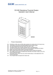
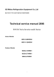
DG-600 Standalone Proximity Reader Operation User's Manual I. Product Characteristic: DG-600 has a 600 cards and PIN codes capacity and a reading time of 0.5-second max. Transmitted to the host with extended Wiegand format auxiliary reader. The Unit will operate with card only, PIN or card, PIN + card. The logical memory does not allow duplicate cards to be programmed. The host unit will lockout for 60 seconds if 5 incorrect password attempts are entered. Beeper sound gives positive signal of all keypad activations. Build in tamper switch that turns on alarm relay to ensure vandal proof operation. Non-volatile memory stores all programmed information for at least 10 years, even in the event of total power failure. Removable memory chip in the main control module allows on site replacement in the event of break down. Fully Programmable via keypad and master code Copyright Gianni Industries, Inc. All Rights Reserved. P-MU-DG600 Ver. C Publish:2009.06.15 Page: 1/ 7 II. Specifications: Operating Voltage DC +8.5V to 16V Current Draw Average 50mA, Peak 100mA @ 12Vdc Transmitting Frequency 125 KHz Memory Volume 600 Proximity cards/tokens and PIN codes Read Range Up to 10 cm (Depending on local installation conditions) Keyboard 12 digits keypad (0~9, *, #) Input Request-to-exit, door reed switch, auxiliary reader Relay Electric Current 2A MAX @30Vdc ;0.4A @ 120Vac The system will shut down for 60 seconds while 5 times of Invalid PIN Lock-out incorrectly Master Codes enrolled or PIN codes attempted (None beeper signal of keypad activations). Strike Time: 1~99 seconds (adjustable) Relocking timer Strike mode: Access Timer or Latch Door Held Open Alarm: 10~990 Alarm Function Door Forced Alarm Panel Temper Alarm DG-600E: Wiegand 44 or 26-bit only format (adjustable), hexadecimal (Em 64-bit standard R/O or compatible) Format DG-600H: Wiegand 26~37 or 26-bit only format (adjustable), hexadecimal (125KHz 26~37-bit R/O or compatible) Case Material ABS (UL94V0) Color Dark gray/ Beige White Operating Temperature -20~+70℃ Ambient Humidity 5~95% relative humidity non-condensing Visual Signals 3 LED display with audible indication (Red/Yellow/Green) EMC Meet CE requirement Copyright Gianni Industries, Inc. All Rights Reserved. P-MU-DG600 Ver. C Publish:2009.06.15 Page: 2/ 7 III. The indicator signal chart: Sound and LED indicator: Mode Signal Condition Yellow LED Power on, Stand-by (Flashing slowly) Green LED Valid entry, lock relay active Red LED Warning, Invalid Card or code, Tamper User Signals LED signal Yellow LED Yellow LED (Flashing) Green LED Programming Signals Programming mode entered Card has been read, awaiting input of PIN codes Slot Position ready to store card Red LED Memory slot already has a card registered User Signals 1 Beep 4 Beeps Sound signal Programming Signals 1 Beep Card presented、Any key pressed Invalid card 、 Data computing error The input data is correct 、 Enters or Exit Programming mode Input mistake, or other operation mistakes, duplicate card 4 Beeps Default Settings: Access Mode Read Card only (00) Format All bits(44-bit or 26~37-bit) Card register None Master Codes 12345 (5 digits) (All) Alarm function Defeat able (00) Relocking timer 5 seconds Pressed key delay time (Time Out) 5 seconds Waiting input PIN codes time 5 seconds Setting mode delay time 25 seconds Terminal connections: CN1 Contacts on block for the system 12 + 8.5 ~ 16 Vdc V GND 、 Power ground D Electrified lock A Electrified lock, (COM) Alarm Common E Door reed switch B Request-to-exit C CN2 Contacts on block for auxiliary reader 12 + 8.5 ~ 16 Vdc V GND 、 Power ground D1 Alarm Common Copyright Gianni Industries, Inc. All Rights Reserved. P-MU-DG600 Ver. C Publish:2009.06.15 D0 DATA1 Wiegand Data 1 DATA0 Wiegand Data 0 LED LED contact BEEP Beeper contact Page: 3/ 7 IV. Wiring diagram: Fail-Safe Lock St 2 connect to 1-2 Contact door switch or the electric lock signal output Fail-Secure Lock St 2 connect to 2-3 Push Button Power supply (10~15Vdc) *Linear supply recommended External relay start the warning system Auxiliary Reader (Wiegand Format) Insert 2-3 position to reset DG-600E Jp1 leads to Wiegand 44 bits format DG-600E Jp1 short-circuit to Wiegand 26 bits format DG-600H Jp1 leads to all Wiegand format Connect to 1-2;C and D contact is N.C. Connect to 2-3; for N.O. Connect to 1-2;C and A contact is N.C. Connect to 2-3; for N.O. DG-600H Jp1 short-circuit to Wiegand 26 bits format For DC use only For AC/DC Note: 1. DG-600 auxiliary reader must not be further than 20 meters from the host. Also this reader should be nearer than 30 centimeters, to avoid disturbance. The suggested wire gauge is #22~26 AWG. 2. DG-600E important instructions: At the back of the main PC board JP1 (see wiring diagram). The system storage card form is Wiegand 44 bits. When you have Wiegand 26 bits auxiliary reader, please do use the solder to short JP1 to turn to Wiegand 26 bits (HEX) form, the auxiliary reader stores different card, this produce invalid card readings 3. DG-600H, the card storage form is Wiegand. If short-circuits JP1 turns Wiegand 26 bits form, can only read Wiegand 26 bits to the system. 4. DG-600E, DG-600H when JP1 has the change, there’s a possibility the card stored would be invalid. Reset to input the card. 5. The door strike must have a vartistor or a diode across the door strike terminals to suppress the back EMF of the strike - failure to do so will damage the relay contacts and electronic components. Copyright Gianni Industries, Inc. All Rights Reserved. P-MU-DG600 Ver. C Publish:2009.06.15 Page: 4/ 7 6. Egresses switch is in N.O. Condition. 7. Alarm system use (C.A. contact) start with external relay. 8. Using a Linear supply power recommended, to prevent power reduction at the card reader. Warranty: The product is warranted against defects in material and workmanship while used in normal service for a period of 1 year from the date of sale to the original customer .GEM policy is one of continual development and improvement , therefore GEM reserves the right to change specifications without notice. Copyright Gianni Industries, Inc. All Rights Reserved. P-MU-DG600 Ver. C Publish:2009.06.15 Page: 5/ 7 V. Operation Instruction WARNING: Please read all of operation instruction before proceeding. Enter Program Mode Enter twice the master code : (Default setting is "12345") → Yellow LED will light up → you are now in the “Programming Mode”. Exiting from the Program Mode Press 「#」 → to exit from the programming mode, or if no activation has happened for 25 seconds , the system will return to the user mode. A. B. C. System Setting Access Mode Enter the Programming Mode, Press 「* 0」+ 「??」 Proximity Only: For Using Card/Tag Only. ?? = 00, setting complete. Proximity or PIN Code to open the door: ?? = 01, setting complete. Proximity + PIN to open the door: Card followed by PIN code to enter. ?? = 02, the setting is complete. Note 1: After using the proximity card the yellow LED blinks and input the PIN codes. If wrong PIN code is input it will automatically return to the “User Mode”. Note 2: 5 continuous wrong pin codes will automatically deletes the card. A. B. Adding and deleting cards Enter the Programming Mode, Press the card storage slot code: 000~599 Green light comes on: This slot code may register the card I. Show card to readerÆYellow light blinks Æ input 5 digits PIN codes Æ Green light offÆ enrolled completed Æ(repeat) II. Show card to readerÆ (4 audible beep) another card has already been input (duplicate card). Red light comes on: This slot already has a code registered I. Press 「**」 (deletion) Æ Green light comes on Æ Show card to reader Æ ﹝same as step “A-1”﹞ II. Enter another slot card position. Note 1: Regardless of system setting access mode select, you must enter a 5-digit PIN codes after showing the card to complete the register program, otherwise the card input will not be successful. Note 2: The master code are not be used for PIN code. A. B. Relocking timer setting Enter the Programming Mode, Press 「*1」+「??」 Pulse mode:?? = 01~99 seconds, 05 represents 5 seconds → (An audible beep) indicates setting successfully→to exit from the programming mode, or program other operating. Latching mode:?? = 00 → (An audible beep) indicates setting successfully→to exit from the programming mode, or program other operating. Note: Enter「00」Sets the relay to latching mode. (Correct code or card entered opens the relay, and the relay stays open until the correct code or card is entered again). Copyright Gianni Industries, Inc. All Rights Reserved. P-MU-DG600 Ver. C Publish:2009.06.15 Page: 6/ 7 Alarm Function A. Enter the Programming Mode, Press 「*2」+「??」 Alarm Setup: Input time ,「??」 = 01~99, 05 represents 50 seconds. B. To turn off alarm function: Input 「00」 Example 1: Door Held Open Alarm If the relocking timer is set for 5 seconds, and the Alarm Setup is set for 10 seconds, the following will happen: If the door has been opened via a valid card or PIN codes, but has remained open for more than 15 seconds then an audible alarm will sound and the RED LED will flash and remain until the door has been closed correctly. This activation is controlled, using contacts 「E」 and 「V」. Example 2: Door Forced Alarm (same example) If the door is opened without the use of a valid card or PIN codes, the audible alarm will sound and the RED LED will flash and remain until the door has been closed correctly. This activation is controlled, using contacts 「E」 and 「V」. Example 3: Panel Tamper Alarm The main panel has a anti-tamper micro switch installed, if the main panel is opened, the audible alarm will sound and the RED LED will flash and remain until the panel has been closed correctly. Changing the Master codes Enter the Programming Mode, Press 「*3」+「?????」the new 5 digit master code →(An audible beep)→enrolled completed→Enter 「#」 to exit from the programming mode, or program other operating. Reset Function A. To Reset the master code only (Return to default setting "12345") Insert the jumper ST1 2-3 position→Green LED will flash→An audible beep→ completed →Return Insert the jumper ST1 to 1-2 position Note: Remove jumper after Yellow LED has been flashing for 5 Seconds. If the jumper is NOT removed then the system will TOTALLY reset and remove all stored information B. Totally reset (remove all stored information) Insert the jumper ST1 2-3 position→Green LED will flash→An audible beep→ Red LED will flash→An audible beep, all parameters reset→Return Insert the jumper ST1 to 1-2 position Copyright Gianni Industries, Inc. All Rights Reserved. P-MU-DG600 Ver. C Publish:2009.06.15 Page: 7/ 7