1
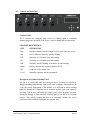
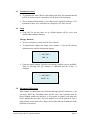
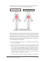
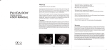
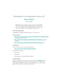
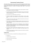
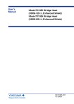
™
CALMARE
Model MC-5A
Non-Invasive Pain
Therapy Treatment
Scrambler Technology
User’s Manual
International Version CE 0470
Competitive Technologies Inc.
Calmare Therapy MC-5A, Operators Manual
November 25, 2008
Page 1
Table of Contents
Item
1.
2.
3.
4.
5.
6.
7.
Page
Indications for Use...................................................................................................... 3
Device Description...................................................................................................... 3
2.1 Device Controls ................................................................................................ 4
2.2 Device Indicators .............................................................................................. 5
2.3 Device Supplies ................................................................................................ 5
Warnings and Contraindications................................................................................. 6
3.1 Warnings ........................................................................................................... 6
3.2 Contraindications .............................................................................................. 6
3.3 Precautions........................................................................................................ 7
Preparation for Use ..................................................................................................... 7
4.1 Instructions for Use........................................................................................... 8
4.2 Controls and Functions ................................................................................... 10
4.3 Treatment Protocol.......................................................................................... 11
4.4 Setup ............................................................................................................... 11
4.5 Placement of Electrodes.................................................................................. 11
4.6 Settings for Correct Usage .............................................................................. 16
4.7 Activation of a Therapy .................................................................................. 16
4.8 Interruption of a Therapy ................................................................................ 19
Troubleshooting ........................................................................................................ 20
Maintenance.............................................................................................................. 20
6.1 Fuse Replacement ........................................................................................... 20
6.2 Cleaning and Disinfection............................................................................... 22
Technical Support ..................................................................................................... 22
Competitive Technologies Inc.
Calmare Therapy MC-5A, Operators Manual
November 25, 2008
Page 2
1. Indications for Use
The Calmare Therapy MC-5A is indicated for use in the symptomatic relief of
chronic, intractable pain, post-surgical and post-traumatic acute pain.
2. Device Description
The Calmare Therapy MC-5A is a 5-channel transcutaneous electrical nerve
stimulator which provides stimulation based on a stored treatment program. Up to 5
pairs of electrodes can be placed on a patient’s body to provide relief from chronic
pain. It can be used by physicians, nurses, therapists, and trained medical personnel.
Two microprocessors operate to ensure proper function of the unit and the treatment
program. The treatment program operates automatically once the device is turned on
and an output level is set on the amplitude control for each channel to suit the
patient’s sensitivity to the stimulation. The electrodes are placed in tandem at points
around the area where pain is experienced to provide relief.
CAUTION:
Federal (USA) law restricts this device to sale by or on the order of a physician.
General Features
Power Supply
200-240V 50/60 Hz
Insulation
Class I
Applied part
BF
Waveforms
Artificial biopotentials modulated for digital synthesis with Scrambler
codes (international patent) made of impulse sequences (strings) of
max. amplitude 42 A C (dual -True RMS) on fictitious load of 10
kohm. Average wave train frequency < 80 Hz.
Protection
Double fuse on the network (2X 800 mA)
Overall absorption
0.3 A max.
Channels
5 independent
Decoupling
Separate output transformers for each channel
Electrode features
Disposable surface electrodes pretreated with GEL in fabric non fabric
Ag/Ag Cl
Competitive Technologies Inc.
Calmare Therapy MC-5A, Operators Manual
November 25, 2008
Page 3
A representation of the Stimulation Waveform is found below:
500 Ω load
7.035ms
16.4ms
T=23.435ms
Output Voltage: 11.875 V p-p
Output Current: 23.78 mA p-p
Output Frequency: 43 Hz
Output Frequency Range: 42-53 Hz
Output Voltage Range: 11.875-118.75V p-p
Output Current Range: 11.875-23.78 mA p-p
2.1
Device Controls
Channels
Synthesis
Control panel
•
On/Off switch in the lower right hand corner marked “Power”.
•
Front panel contains 5 knobs marked level which control the stimulation
output of the treatment.
Competitive Technologies Inc.
Calmare Therapy MC-5A, Operators Manual
November 25, 2008
Page 4
•
2.2
Navigation buttons (A (left), B (right), C (up), D (down)-Ok) according to
the layout displayed. They enable to modify the setup, to switch the end-oftreatment alert on and off, and to cancel a therapy.
Device Indicators
•
The five channels are equipped with a series of warning lights which
constantly monitor the proper operation of the device, correct cabling, and
its functioning.
Channel Indicators
2.3
REF.
DESCRIPTION
Rdy
Indicates channel on hold (output level on zero) and ready to use
Scn
Service Monitor. Normally quickly flashing
Fdk
Normally on, if channel is up and running
Ok
Normally on, if channel is up and running
Hld
Normally quickly flashing, if channel is up and running
Meter
Displays the stimulus intensity applied (10/70)
Out
Connector of the output wire
Level
Manually regulates stimulus magnitude
Device Supplies
1.
10 Self Adhesive disposable surface snap
electrodes pretreated with Gel
2.
5 Lead wires with connectors as shown
3.
AC Power Supply – 220 Volt 50/60 Hz
4.
Instruction Manual-instructions for use by physician or by trained
medical personnel.
Competitive Technologies Inc.
Calmare Therapy MC-5A, Operators Manual
November 25, 2008
Page 5
3. Warnings and Contraindications
3.1
3.2
Warnings
•
The safety of the Calmare MC-5A device for use during pregnancy or labor
has not been established.
•
The Calmare MC-5A device may not be effective for pain originating in the
central nervous system. This includes headaches.
•
The Calmare MC-5A device should be used only under the continued
supervision of a physician, or trained medical personnel.
•
The Calmare MC-5A device does not cure the underlying cause of the pain.
•
The Calmare MC-5A device provides a symptomatic treatment and as such
suppresses the sensation of pain which would otherwise serve as a protective
mechanism.
•
Keep out of reach of children.
•
Electronic monitoring equipment (such as ECG monitors and ECG alarms)
may not operate properly when the device is in use.
•
The long-term effects of chronic electrical stimulation are unknown.
•
Stimulation should not be applied over the neck or mouth. Severe spasm of
the laryngeal and pharyngeal muscles may occur and the contractions may
be strong enough to close the airway or cause difficulty in breathing.
•
The use of this device is forbidden in the presence of inflammable anesthetic
gases.
Contraindications
•
DO NOT use on patients with metal implants such as pacemakers, automatic
defibrillators, aneurysm clips, vena cava clips and skull plates.
•
However, the Calmare MC-5A device CAN BE USED on patients with
metal implants such as total knee, hip, shoulder and other joint replacements
as well as on patients with implanted pins, clips, screws, plates and cages
used for orthopedic repair.
•
DO NOT place electrodes on the carotid sinus (front of neck) region of the
body.
•
DO NOT place electrodes on the head unless under direct supervision of the
clinician.
Competitive Technologies Inc.
Calmare Therapy MC-5A, Operators Manual
November 25, 2008
Page 6
3.3
•
DO NOT use on patients prone to seizure (for example, epileptics).
•
DO NOT use on undiagnosed pain.
Precautions
•
Isolated cases of skin irritation may occur at the site of electrode placement
following long-term application.
•
Caution should be used for patients with suspected or diagnosed heart
problems.
•
Caution should be used for patients with suspected or diagnosed epilepsy.
•
Effectiveness of the Calmare MC-5A device is highly dependent upon
patient selection by a person qualified in the management of pain patients.
•
Caution should be used when treating in the presence of the following:
•
Patients with a tendency to hemorrhage following acute trauma or
fracture;
•
Painful area over the menstruating or pregnant uterus;
•
Areas of the skin that lack normal sensation.
•
Some patients may experience skin irritation or hypersensitivity due to the
electrical stimulation, electrical conductive medium or stainless steel
electrode array. The irritation can usually be reduced by using an alternate
electrode placement.
•
Electrode placement and stimulation settings should be based on the
guidance of the prescribing practitioner.
•
Avoid use of electrodes, conductive gels, lead wires, or accessories other
than those supplied with the system or recommended by Competitive
Technologies. The safety of other products has not been established and
their use may result in skin irritations and burns beneath the electrodes.
4. Preparation for Use
•
To correctly function in the required conditions of use, the device needs an
electric system fitted with an automatic circuit breaker and earthing in the power
point used for the system.
•
MC-5A is a device specifically designed for hospital and outpatient facilities. It's
easily transportable and mechanically robust.
Competitive Technologies Inc.
Calmare Therapy MC-5A, Operators Manual
November 25, 2008
Page 7
4.1
Instructions for Use
1. In order to operate, the MC-5A must be placed on a flat, stable surface.
2. Cable assembly will follow the steps illustrated in the power cabling picture
below.
3. Position the power supply unit near the MC-5A. Plug the network cable into
the adapter’s empty socket and the power source (220/230 V 50/60 Hz)
checking its regulatory compliance, in that it must include a grounded
socket and automatic cut-out on the power line. The MC-5A must be
compliant to increase its operational safety to avoid accidents. The MC-5A
has a further set of independent protection measures, such as low voltage
picked up in the output by the power supply unit that drives another low
tension power transformer/separator contained inside, plus an outbound
transformer/separator that in a galvanic way isolates every channel from low
voltage power supply and from other channels, rapid self-restoring fuses,
and patient-insulation relays.
4. Connect electrode cables in the appropriate socket in every channel by
gently inserting the plug, making sure it is snug and then locking the cable
to the device by turning the metal collar clockwise until tight. At the ends
Competitive Technologies Inc.
Calmare Therapy MC-5A, Operators Manual
November 25, 2008
Page 8
of each cable there are 4 mm plugs with a snap-type connection. If different
types of electrode connections are required, do not modify the cable, but
simply replace the adapter.
Picture of the cables (electrode side) and plugging into the MC-5A
5. Electrodes are inserted by pressing on the button connection.
6. Completely rotate the 5 knobs counterclockwise on the front panel.
7. Once these tasks have been completed, the device is ready for use and can
be turned on. To modify the default operating parameters, it is possible to
change the setup as explained in the “Setup” section.
Competitive Technologies Inc.
Calmare Therapy MC-5A, Operators Manual
November 25, 2008
Page 9
4.2
Controls and Functions
Control Guide
The 5 channels are equipped with a series of warning lights to constantly
monitor the proper operation of the device, correct cabling and its functioning.
CHANNEL DESCRIPTION
REF.
DESCRIPTION
Rdy
Indicates channel on hold (output level on zero) and ready to use
Scn
Service Monitor, normally quickly flashing
Fdk
Normally on, if channel is up and running
Ok
Normally on, if channel is up and running
Hld
Normally quickly flashing, if channel is up and running
Meter
Displays the stimulus intensity applied (10/70)
Out
Connector of the output wire
Level
Manually regulates stimulus magnitude
Description of Synthesis Module Panel
MC-5A is a system that uses two microprocessors operating in correlation,
though operating independently. One is fully used to manage code synthesis. To
verify the correct functioning of the module, it is sufficient to check warning
lights M1 through M7. When the device is turned on, they light up in sequence,
and then flash in sync, indicating the stand-by and correct program operation.
During the therapy, at short intervals, warning lights go on and off in a random
manner. This activity enables the device to constantly monitor the correct
operation of the module and program in a dynamic way.
Competitive Technologies Inc.
Calmare Therapy MC-5A, Operators Manual
November 25, 2008
Page 10
4.3
4.4
Treatment Protocol
•
To guarantee the most effective and lasting pain relief, the treatment should
last 30-45 minutes, but it is possible to set up from 20 to 60 minutes.
•
The treatment should include cycles (that can be repeated) made up of 10
treatments at least, to be carried out at a frequency of 5 times a week.
Setup
•
If the MC-5A has not been set up, default options will be active that
establish the treatment duration:
Therapy Duration
•
30 min. to 45 min. (it can be set from 20 to 60 min.)
•
To intentionally change this Setup, press buttons C (Up) and D (Down)
simultaneously until the Setup menu appears.
------ SET TIME ---TIME 30
•
Using navigator buttons Up/Down the therapy duration can be modified.
Then, by pressing OK, the duration is confirmed and the “Setup” is
complete.
------ SET TIME ---WRITE 30
4.5
Placement of Electrodes
Each channel is connected to two electrodes through specific connectors, a red
one and a black one. Excluding some specific cases, the electrodes must be
placed slightly outside the pain area. It is necessary to identify each pain area
before placing the electrodes. The best method is to ask the patient to exert a
light pressure on the skin with a finger until he/she finds the boundaries of the
pain area to be treated.
Competitive Technologies Inc.
Calmare Therapy MC-5A, Operators Manual
November 25, 2008
Page 11
Each channel’s two electrodes (red and black pair) must be positioned 2 to 3
inches away from the area of pain as shown in the figure below:
Vertical placement
Horizontal placement
Figure 1. Example Electrode Patients
(the numbers on electrodes indicate the channel)
Please note in the above example that in the first case, the electrodes have been
placed vertically and in the second case, the electrodes are placed horizontally
passing through the center of the pain area. The positions of the electrodes
correspond to some forms of pain that respond better to a vertical placement and
other forms of pain that respond better to horizontal placement. Please note the
following regarding electrode placement:
•
The red and black paired electrodes of each channel can be placed either
vertically or horizontally.
•
All the vertical placements must have the same color electrodes of each
channel on the same side. The same is true for horizontal placements. If this
rule is not followed, the pain-killing effect drops. For example, if channel 1
and 2 are placed vertically, and the red electrode of channel 1 is placed on
the top then the red electrode of channel 2 will have to be placed on the top.
If the black electrode of channel 1 is placed on the top then the black
electrode of channel 2 must be placed on the top.
•
If the red electrode of channel 1 is placed on the right, the red electrode of
Competitive Technologies Inc.
Calmare Therapy MC-5A, Operators Manual
November 25, 2008
Page 12
channel 2 must also be placed on the right, and so on.
•
Chronic pain should be treated using the electrode pairs of several channels.
An example of chronic pain is low back pain. Usually the low back pain
area must be treated with one or more channels (according to the extent of
the pain area) with a horizontal placement. The part of pain that spreads to
lower extremities passing through the gluteus, must be treated with a
vertical placement. These two types of placements are used simultaneously
during the same treatment session.
The following illustration (Figure 2) is an example of placements that
concurrently use more channels vertically or horizontally + vertically. The
numbers on the electrodes correspond to the channel. For example, red 1 and
black 1 are the electrodes that use channel 1, red 3 and black 3 are the electrodes
connected to channel 3, and so on.
Vertical Assembling
Horizontal and Vertical
Assembling
Figure 2. Example of Multiple Channel Use
Important Notes When using Multiple Channels
a. Start by preparing to use only one channel according to the descriptions
above. Once the connections have been made, the level is adjusted
following the descriptions above.
Competitive Technologies Inc.
Calmare Therapy MC-5A, Operators Manual
November 25, 2008
Page 13
b. In case the pain is reduced, but it is still present in some areas, while the first
inserted channel is active, add another one to extend the treated area,
following the same instructions. After having verified the pain relief of the
new inserted electrode and channel, continue treatment until the complete
disappearance of pain.
c. If the addition of electrodes and channels do not produce results, set the
level to zero and use a different electrode placement repeating the operation
of set-up and efficacy control.
d. Proceeding through a number of subsequent attempts, one can quickly
understand when electrodes are correctly placed, because pain immediately
disappears from the treated area. By using this feedback, it is possible to
resolve the most complex situations thanks to the immediate response of full
or substantial relief of the pain symptoms.
Additional Treatment Positioning
If it is difficult to identify pain free areas useful for treatment, it is possible to
use advanced positioning strategies that usually solve the problem. A strategy is
to use contralateral areas. Please see the examples below in Figure 3.
Figure 3. Additional Placement Positioning
Note: All described positioning types are valid for any area of the body.
In the example on the left, a diagonal (X-shaped) is used for positioning
channels 1 and 3, and channel 2 vertically. The figure on the right demonstrates
the diagonal placement of channels 2 and 4, and channel 1 placed vertically and
Competitive Technologies Inc.
Calmare Therapy MC-5A, Operators Manual
November 25, 2008
Page 14
channel 3 horizontally. These examples provide various positions that cover the
pain area in several directions. These examples require the use of multiple
channels. When using these examples please remember the following:
•
It is important to remember that the sign of correct treatment and electrode
placement is the reduction of pain in the areas involved.
•
In cases when the pain occurs only in specific positions, make sure to
position electrodes and monitor efficacy only when there is pain; otherwise,
the therapy cannot be effective. Once you are certain of the correct
positioning, the patient can choose the position he is more comfortable with
to continue the treatment.
•
In difficult cases always try one channel at a time, checking its efficacy. If
the time required for positioning reduces the length of the actual treatment,
you should set the levels of each channel to zero without changing the
positioning, then interrupt the therapy through the specific controls and start
it on again to carry out a full treatment correctly.
•
During the treatment the stimulation might be perceived with minor
intensity because of the pain relieving effect. In this case it is necessary to
increase the levels of the channels involved until the patient reports he/she
clearly perceives the stimulation.
Therapy Duration
In most sessions, the treatment lasts 30 to 45 minutes but can run anywhere
between 20 and 60 minutes in length.
Treatment Initiation
The treatment automatically starts when the level of any channel is raised, and
automatically stops at the end of the duration previously set.
The treatment is completely automated and does not require setting up of
individual wave parameters such as frequency, duty cycles, scanning etc. The
only manual procedure required is the regulation of the stimulus magnitude, to
be customized to the patient’s individual sensitivity.
In case of power failure the treatment picks up again from interruption time, but
it is also possible, if necessary, to manually cancel it and then restart the
treatment.
Competitive Technologies Inc.
Calmare Therapy MC-5A, Operators Manual
November 25, 2008
Page 15
4.6
4.7
Settings for Correct Usage
•
Set the channels’ amplitude to the maximum value of the threshold of
tolerance of individual patients. Do not exceed this threshold as it does not
improve the therapy.
•
The ideal setup threshold is the one that enables the subject to feel
stimulation on both electrodes of every active channel that does not provide
discomfort.
•
If more than one channel is used, set one channel at a time, and after having
verified its pain relieving efficiency, proceed to setting the other channel.
•
If the electrode placement is not effective and there is no affect, the channel
must be set to zero, and the electrodes’ position must be changed and the
setup operation repeated.
•
Discontinue use if the signal is felt only on one of the two electrodes.
Check the position to ensure correct operation.
•
Ensure that the patient does not have pain or discomfort under the
electrodes. In this case the electrodes must be repositioned slightly away
from the area chosen to eliminate the problem and achieve the analgesic
effect. Failure to follow these indications can lead to undesirable effects
during or after the treatment.
•
Impulses emitted by the device frequently vary and the patient must be
informed that he/she will often have various sensations at the electrode site.
•
Ensure that positioning is correct from an electronic and operational point of
view by asking the patient whether he/she is able to feel the pain after every
channel has been turned on. If the patient responds with any answer other
than no, please set the channels to zero and begin again.
Activation of a Therapy
When turning MC-5A on, check if there are any previously stored treatments
that have not been completed. This happens when the device is turned off before
the treatment has been completed which will be automatically stored. When the
device is turned back on, the memory enables an automatic restart of treatment
from where it was interrupted. This is useful when the shutdown is erroneous, or
due to a power outage.
If shutdown occurs, a clear message is displayed, and there are two options. The
first one is to restart the therapy in memory, following the same steps as
Competitive Technologies Inc.
Calmare Therapy MC-5A, Operators Manual
November 25, 2008
Page 16
previously described start a new treatment. This is useful if the treatment was
interrupted for a short-term power outage, and the same patient must complete
the treatment. In this case, the start time is the moment when the treatment was
interrupted. The second option is to cancel the therapy in memory. To do so,
one must push the B (right) and A (left) navigation buttons simultaneously for a
few seconds at the same time. Once the therapy is cancelled, the warning
message will disappear.
-- Calmare Therapy -Therapy in memory!
<Ready to start>
1. Before increasing the level of the channel, ensure the cable is connected
correctly between the channel output and the electrodes. Even if not
necessary, it is preferable to put another drop of gel on the conductive part
of the electrode placed on the skin. NEVER REUSE patient electrodes.
2. Very slowly rotate the channel control handle until a relay click is heard and
service information will be shown on the display. The warning signal OK
will appear, while RDY will turn off. If this does not occur, the cable
connection is incorrect and the level control must be completely rotated
counterclockwise to set the channel to stand-by mode. Subsequently, the
entire operation must be repeated after completing the positioning checks.
3. Continue to very slowly rotate the control knob intensity until the patient
feels the stimulation from the channel that is being used. It is normal to
perceive one of the two electrodes more intensely. Once the treatment is
underway, the Display will show the time left to the end of the treatment,
the activation of the end-of-therapy alert sound, and the current status of the
therapy.
-- Scrambler active -Time Out 10 min.
Beep On
Phase 1
4. This operation needs to be repeated for each channel used.
5. For the correct functioning the warning lights Ok, Fdk must be consistently
lit. The letters Scn and Hld will flash consistently.
6. During the set up, if the warning light Ok turns off, an alert signal is
Competitive Technologies Inc.
Calmare Therapy MC-5A, Operators Manual
November 25, 2008
Page 17
immediately displayed with a “feedback absent” message. The turning off of
the warning light Ok can be caused by:
•
Broken or short-circuited cable
•
Cable disconnected from the electrodes
•
Bad electrode contact
•
Insufficient or deteriorated gel on the electrodes.
-- Feedback absent -1 – Zero levels
2 – Check cables
3 – Restart
7. To stop the alert signal, set the outbound levels of all channels to zero. After
having checked and corrected the anomaly, the channel can be again used
without having to cancel and restart the treatment.
8. During normal operation, the meter will show a different position according
to the power requested, the rotation of the level control dial, and the limit set
for power supply under safety conditions, that is automatically adjusted.
This leads to a non-linearity between the increase in the rotation of level
control and the indication of actual power delivery, influenced by the
feedback loop of the circuits controlling the forwarding of Scrambler codes
and skin impedance. The ratio of the level control rotation and meter
indication varies from patient to patient.
Please note that this difference from patient to patient depends on the area that
is being treated, individual sensitivity, and alterations in pain perception.
Competitive Technologies Inc.
Calmare Therapy MC-5A, Operators Manual
November 25, 2008
Page 18
Caution: If an electrode or cable is disconnected, do not place it again on
the patient before having set to zero the channel intensity level or related
alarm. If you do not follow this procedure, the patient may feel a slight
shock that is minor in nature.
Even when the protection system is on, remember it will always react a
couple of seconds after a connection fails.
Operational Checks
The patient should feel immediate pain relief and no stimulation trouble during
use. Any discomfort should be evaluated immediately. If the correct treatment
areas are difficult to find, a response that produces a partial pain-relief is
acceptable, as long as the patient does not feel a stimulation discomfort.
4.8
Interruption of a Therapy
•
To cancel a therapy, press the two navigator A (right) and B (left) buttons at
the same time and wait for the message confirming the interruption.
•
The treatment must not be interrupted by turning off the device, otherwise
the subsequent treatment could start from the amount of time that has not
been used in the previous one.
Complete therapy
Zero levels
Activate/Deactivate END-OF TREATMENT ALERT SOUND
During active therapy, press the OK button in the middle of the navigator to
switch on (Beep On the display), or switch off (Beep off on the display) the
end-of-treatment sound alert.
This command is stored every time the treatment is turned on. Every time the
device is turned on, the Beep on/beep off status will be the same that was more
recently set and stored.
Please note that for safety reasons it is impossible to disable the sound
alerts.
Competitive Technologies Inc.
Calmare Therapy MC-5A, Operators Manual
November 25, 2008
Page 19
5. Troubleshooting
Problem
It is impossible to turn the MC-5A on.
The MC-5A starts at a different time from
the one set.
The line error message appears.
One or two channels do not work.
In the ready position, synthesis module’s
vertical warning signals do not flash.
During treatment, synthesis module’s
vertical warning signals are fixed.
Solution
Verify the connection to the power supply unit and the
electrical power network. If all is in place, call for
assistance.
The previous therapy has not been completed. Cancel the
therapy and restart the procedure.
Check the cabling and verify the presence of faulty
cables, wrongly connected electrodes, without or with
insufficient GEL. If the problem persists, call for
assistance.
Turn the device off and on once again. If the problem
persists, call for assistance.
Turn the device off and on once again. If the problem
persists, call for assistance.
Turn the device off and on once again. If the problem
persists, call for assistance.
6. Maintenance
The system, with the exception of a routine check of the cables to be connected to the
patient, does not require ordinary maintenance and/or calibration operations.
No fluids should be used to clean the outside area of the device, but simply a simple
duster. If necessary, for a thorough cleaning use a cloth soaked in alcohol, after
having disconnected the device from the main power supply.
After cleaning, carefully check whether the wiring for correct operation has loosened
and if so, tighten the cables.
6.1
Fuse Replacement
The device has two fuses on the network that, whenever necessary, must be
replaced with others of the same value (0.8A). The user can change only one of
the two fuses that are accessible from outside. If the inner fuse must be
replaced, the manufacturer must be called to send an authorized technician to
carry out the procedure.
To replace the external fuse, inside the mains cable tray, it is necessary to:
1. Disconnect the main cable, if present.
2. Push the unlock lever and extract the fuse-holder, with the use of a small flat
blade screwdriver.
Competitive Technologies Inc.
Calmare Therapy MC-5A, Operators Manual
November 25, 2008
Page 20
Remove the fuse and replace it with one of the same value.
Please use the extra fuse located under the operating one if necessary.
3. Re-insert the new fuse in the fuse-holder in the appropriate lock. Correctly
position the entire fuse-holder in its slot, gently pushing it in until it locks.
Competitive Technologies Inc.
Calmare Therapy MC-5A, Operators Manual
November 25, 2008
Page 21
6.2
Cleaning and Disinfection
MC-5A is not a sterile device. Please follow the following:
•
Disposable electrodes to be replaced after every treatment.
•
Periodic cleaning of connection cables to patient with commercial non-oily
disinfectants.
•
The device should not be used on open wounds or in contact with other
biological fluids.
7. Technical Support
GEOMC Co., Ltd.
17F Samsung Fire B/D, #1329 Seocho-2Dong,
Seocho-Gu, Seoul, Korea
Tel: +82-2-586-6871
Fax: +82-2-3486-0445
Made in Korea for Competitive Technologies
CE 0470
Competitive Technologies Inc.
Calmare Therapy MC-5A, Operators Manual
November 25, 2008
Page 22