1
2008:004
MASTER'S THESIS
Study and Automation of a Test System
for Space Instrument Calibration
Maria del Carmen Islas Bravo
Luleå University of Technology
Master Thesis, Continuation Courses
Space Science and Technology
Department of Space Science, Kiruna
2008:004 - ISSN: 1653-0187 - ISRN: LTU-PB-EX--08/004--SE
Department of Space Science, Kiruna Space Campus
Joint European Master in Space Science and Technology
ASTROPHYSIQUE : Techniques Spatiales et Instrumentation
MASTER THESIS
STUDY AND AUTOMATION OF A TEST
SYSTEM FOR SPACE INSTRUMENT
CALIBRATION
María del Carmen Islas Bravo
Supervisors:
Dr. Claude Aoustin
Dr. Victoria Barabash
July 2007
ABSTRACT
Nowadays the independency of systems is a valuable requirement
due to its implications in saving cost and time. Systems that are constantly
dependent on an operator for their survival are outdated. Everyday more
users demand from a system to be autonomous, robust and reliable. This
was the need found at the CESR laboratory. A test system, used for space
instrument tuning before launch, needed to be manually manipulated. This
resulted in the operators’ time loss and long duration of instrument
calibrations.
Through this work a program for the automation of a calibration test
system from the CESR (Centre d’Etude Spatiale des Rayonnements) was
developed and added to improve a previous version. The test system is
used to tune space instruments before launch. The main parts of the system
are an ion beam, a mass spectrometer, an ion detector and a vacuum
chamber. The configuration of the system includes some of the next
features: on/off of the beam, tuning current intensity, positioning the ion
beam or the instrument located in the chamber, data handling, data saving,
reading of the configuration parameters, etc.
LabWindows/CVI, National Instruments programming software, was
used for generating the program. Connections between the system and the
PC were done either through two RS232 serial ports (COM1 and COM2), or
through two National Instrument acquisition cards connected to the PC.
Overall study of the system was needed. An extensive revision of the
work done for the automation of the system was done in order to suggest
modifications in some malfunctions, and to add new features. Modifications
were made to the existing version to improve its performance. New
functionalities that control different motors in the system were developed.
And finally, the full program was integrated for future use.
A full
documentation was developed in parallel to the work for further reference.
A program resulted that can configure the system to a given state
and independently realize different desired scans to an instrument located
in the chamber. The motion of the instrument, the beam, and the step
between each position for consecutive scanning can be given. The intensity
of the current in the filament of the ion beam can also be varied.
This report shows the different stages of the project and the
background needed to develop it.
1
To my parents who never limited my dreams.
To Pepe, Ana Luisa and Juan Pablo who are my dream mates.
ACKNOLEDGEMENTS
I want to thank Monsieur Claude Aoustin for the opportunity to join this
project, for all the knowledge shared not only on theory matters but also for
everyday life. Thank you for the understanding, the opportunity to keep
growing in professional and personal ways, and contribution to correct my
mistakes in the French language.
I want to thank Eric Lecomte for his knowledge contribution in the technical
aspects of the system. Thank you for the nice talks, the French music and
your help for improving my French.
I want to thank Sven Molin for all the work and time he has put in making
the Master Program work and become real. Thank you for the constant
concerns for each of the students.
I want to thank Monsieur Christophe Peymirat for his help in introducing us
to the French studying system and his help in finding a position for this
thesis work when it became hard to find a place to do it in the French
industry.
I want to thank Dr. Victoria Barabash for her contribution to this work and
the support she gave me during my studies.
I want to thank to all the spacemasters. Thank you for the great moments
we have been living in the last two years. It has been a pleasure to get to
know this international group and learn many things from each of you.
I want to thank all the professors of the program for their personal
contribution to my studies, and the possible application of it through this
work.
I want to thank Maxime Chauvin and Monsieur Claude Aoustin for their help
with the correction in the French grammar used in the report, and also
Reiko Corbeil and Piort Perczynski for the revision of the English part.
2
INDEX
1. INTRODUCTION……………………………………………………………………………………
4
1.1 The CESR - Centre d’Etude Spatiale des Rayonnements………
4
1.2 Low Energy Test System ………………………………………………………
5
1.3 The Project ……………………………………………………………………………… 6
1.4 LabWindows/CVI ……………………………………………………………………
7
2. OBJETIVES
2.1 General Objective …………………………………………………………………… 8
2.2 Specific Objectives …………………………………………………………………
8
3. BACKGROUND INFORMATION
3.1 System Description ………………………………………………………………… 9
3.1.1 Ion Source ………………………………………………………………… 9
3.1.2 Mass Spectrometer …………………………………………………… 10
3.1.3 Ion Detectors ……………………………………………………………
11
3.2 System Command …………………………………………………………………
11
4 LCPB – Logiciel du Commande du Petit Banc ……………………………………… 14
4.1 LCPB – Previous Version ………………………………………………………… 14
4.1.1 Current in the Filament……………………………………………… 16
4.2 IP28 – PC Communication……………………………………………………….. 18
4.3 Motors Command Software……………………………………………………… 20
4.3.1 The Movement of the Motors ……………………………………
22
4.3.2 Scan Routine………………………………………………………………
22
4.3.3 Security Features………………………………………………………… 24
4.4 LCPB – New Version ………………………………………………………………… 26
5. CONCLUSIONS ……………………………………………………………………………………… 27
6. FUTURE WORK ……………………………………………………………………………………… 28
7. GLOSSARY ……………………………………………………………………………………………. 29
8. REFERENCES ………………………………………………………………………………………… 30
A. ANNEX I ……………………………………………………………………………………………….. 31
3
1. INTRODUCTION
Nowadays, the functional independence of a system is a valuable
feature due to its implications in lowering costs and saving time. Systems
that are constantly dependent on an operator are outdated. Everyday more
users demand from a system to be autonomous, robust and reliable. In the
CESR laboratory, a test system, used for space instrument tuning before
launch, has to be manually manipulated, which inevitably results in a loss of
time for the operators and long duration of instrument calibrations.
This section consists of a general description of the laboratory in
which the project was developed, as well as descriptions of the project and
the programming software used. For further information, refer to the
following sections.
1.1 The CESR - Centre d’Etude Spatiale des Rayonnements
The project was developed at the CESR, a space astrophysics
laboratory located in Toulouse, France. This research institute belongs to
the CNRS (Centre National de la Recherche Scientifique – National Center of
Scientific Research) of France and the University Paul Sabatier. It is
attached to the research units of Physique Chimie et Automatique and the
Observatoire de Midi Pyrénées of the University.
The missions of the laboratory include astrophysics and
astrochemistry research, the development of space instrumentation, the
training of personnel and the dissemination of knowledge. It is organized in
three scientific and technical departments, according to the study fields:
-
Solar System (space plasmas and planetology)
-
High Universe Energies
-
Cold Universe
During my stay in the laboratory I joined the Solar System
Department. The studies in this department are focus on two main fields:
the study of the ionised environment of the planetary, interplanetary and
hemispheric environments, and the study of the surfaces and atmospheres
of terrestrial planets.
The CESR plays a very significant role in European space activities,
with all the development of on-board spectrometers, mass spectrometers
for on-site measurements and teleobservation of surfaces with gamma
instruments.
In order to study and calibrate the performance of the spectrometers
or ion/electron detectors, the Solar System department has two test
systems. They are classified according to their working energies as follows.
-
High Energy Test System
o
Ion beam: 1keV – 10keV
o
Electron beam: some eV – 10keV
4
-
Low Energy Test System
o
Ion beam: some eV – 800eV
It is for the Low Energy Test System which the automation presented
in this work has been carried out.
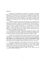
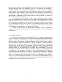
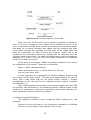
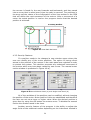
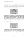
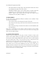
1.2 Low Energy Test System
The test system is mainly composed of an ion beam that generates
particles to be detected, and a vacuum chamber where the instrument to be
calibrated is placed. The low pressure (10-6 mbar) inside the system is
needed to verify the performance of the ion detectors (space instruments)
that have to be tested. These pressure levels are also needed to operate
with the detectors used inside the instruments (micro channel plates). In
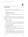
Figure 1.1 the complete system is presented.
Figure 1.1 Low Energy Test System
As can be seen the beam, the ion detector (Faraday detector) and its
electronic control devices are placed at the top of the vacuum chamber. To
5
create the vacuum inside the chamber, three pumps are located under the
chamber. The required vacuum is achieved as follows:
-
Primary pump is used to get an average of 10 mbar.
-
Then the secondary pump decreases the pressure down to 2x10⁻⁶
mbar.
-
The Ionic pump is activated when the pressure is around 10-5 and
decreases the pressure close to 8x10⁻⁷ mbar.
The instrument that has to be calibrated is located inside the
chamber. The types of instruments that are calibrated in this system are ion
analyzers that will be on board spacecrafts. For tuning the instruments,
different ion species, energies and directions can be set.
The system has, as shown in Figure 1.1, five displacement motors (3
translations and 2 rotations). Two of them allow the horizontal translation of
the beam with respect to the vacuum chamber (x and y). This motion
locates the ion ray in the desired position with respect to the instrument
that is inside the vacuum chamber. The instrument is fixed with respect to
its translational axes, but has two degrees of freedom in its rotation motion
(α and β), which makes it possible to obtain the desired inclination of the
target with respect to the ray. Finally one last motor locates a flux
measurement device in the ion ray trajectory. Its displacement is in the y
axis. This ion detector can be moved in or out of the trajectory with a motor
F shown on Figure 1.1. It is used to observe the ion ray on an oscilloscope
to verify the ion beam (intensity and shape) arriving to the entrance of the
instrument that has to be calibrated.
1.3 The Project
For several years the test system was commanded by two different
PCs with MS-DOS operating systems and programs based on Pascal
language. With the development of new technologies and solutions from the
industry, the old configuration became inefficient and outdated. The need
for better system performance and autonomy was evident, and the
automation of the system started two years ago.
The hardware configuration was the first step for the automation of
the system. Hardware changes were done to implement the connections
between the different controls from the system and the new PC with
Windows XP operating system. Changes in the electronics were also done
allowing the possibility for the user to choose between manual or automatic
manipulation of the different controls. An improved layout of the electronic
circuit of different special commands in the system was built.
After this, the second stage of the automation was the development
of a primary program to control the main features of the ion beam. The
program had an interface allowing the user to modify different variables of
the beam, and also the possibility to launch a scan of the ion ray to identify
the elements present in it.
The work presented here is the third stage of the automation of the
system. At first a study of the old program was done in order to improve
6
features and modify some malfunctions that were found. This helped to
become familiar with the software used for developing the program LabWindows/CVI that allows programming in C++ with a friendly
environment. The continuation of the automation was also kept updated. A
new program was created to control four motors located in the system and
to enable the launching of scanning routines when the calibration of a space
instrument is required. A full documentation was developed in parallel to
the work for further reference.
The final goal in third stage of the system automation was a program
that can configure the system to a given state and independently realize
different desired scans to an instrument located in the chamber. The motion
of the instrument and the beam as well as the step between each position
for consecutive scanning can be given. The intensity of the current in the
filament of the ion beam is also a variable of the system that can be
modified with the program in the scanning routines.
Further work can still be developed to achieve a fully independent
system and improve the performance of the existing one. This is presented
in Section 6.
1.4 LabWindows/CVI
National Instruments LabWindows/CVI is a software development
system for ANSI C programmers for test and measurement applications that
greatly increase the productivity of engineers and scientists. It is used to
develop high-performance, stable applications in the manufacture, military
and aerospace, telecommunications, design validation, and automotive
industries. It contains an interactive environment for developing programs
and libraries of functions for creating data acquisition and instrument
control applications. LabWindows/CVI contains a comprehensive set of
software tools for data acquisition, analysis, and presentation. It has an
interactive environment for editing, compiling, linking, and debugging ANSI
C programs. The programs written in the LabWindows/CVI interactive
environment must adhere to the ANSI C specification. In addition, different
tools can be used: compiled C object modules, Dynamic Link Libraries
(DLLs), C libraries, and instrument drivers in conjunction with ANSI C
source files when developing programs. The power of LabWindows/CVI lies
in its libraries. The libraries have functions for developing all phases of data
acquisition and instrument control systems [1].
7
2. OBJECTIVES
2.1 General Objective
The main aim of this work is to continue the automation of the
calibration test system of the CESR used for tuning space instruments.
2.2 Specific Objectives
-
Get vast knowledge of the test system in order to understand its
functions.
-
Study the hardware connection of the system with the PC.
-
Learn the use of LabWindows/CVI.
-
Study the program code of the LCPB (Logiciel de Command du Petit
Banc).
-
Revision of previous work done for the automation of the system.
-
Check for modifications that can be done or need to be done in the
previous work.
-
Make changes and respective tests of the system.
-
Develop the program that controls the motion of the motors of the
system.
-
Test and improve the program for better performance.
-
Add a new program to the existing one.
-
Overall test of the system.
-
Write a user manual for the new part.
-
Document the algorithm used for the different parts of
programming, for future modifications of the code.
-
Show the features of the new program to the future user.
8
the
3. BACKGROUND INFORMATION
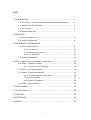
3.1 System Description
The ion beam consists of an ionization chamber, mass spectrometer,
Faraday detector and instruments for controlling the devices. Usually it is
used for gas mix analysis (molecule content and proportion in a mixture).
Its different working stages are: injection of gas, ionization of the gas, and
mass selection by the quadrupole mass spectrometer also called mass filter,
and the measurement of the selected ions.
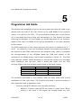
3.1.1 Ion Source
The ion source contains two rhenium filaments (main and redundant).
The filament is the system cathode of the electrons accelerometer. The
current through the filament can be in the range of values from 70 to 600
µA. The filament is warmed up and placed in a lower potential of the one of
the gas that will be ionized. The high temperature allows the ejection of
some electrons from the filament, and the differential potential accelerates
them towards the chamber containing the gas to be ionized. The emitted
electrons will have energy of 70 eV at the moment when they arrive to the
chamber containing the residual gas. This potential is found between the
Wehlnelt electrode and the ionization chamber. The collision of the electrons
with the gas particles leads to the ionization of the gas. The ions will be
extracted through the diaphragm that produces in the chamber a weak
electric field that will pull them out. The lenses will focus the ions that will
arrive to the mass filter for the ions selection. The spectrometer exposes
the ions to high frequency electric fields crossed in a way that only the ions
with a certain relation mass/charge will go through. The selected ions will
be accelerated to the output of the spectrometer by a potential difference of
0 V to 800 V. The resulted ion beam can be either reflected towards the
vacuum chamber, so the space instruments can be tuned, or pointed to the
Faraday detector, so an analysis of the ions in the beam is done. In Figure
3.1 the ion source structure with its parts can be seen [6, 8-10].
Figure 3.1 Ion Source
9
The potential difference between the electron collision chamber (were
the ions are created) and the ground is higher than the potential difference
found between the electron collision chamber and the ion source (cathode).
As a consequence, the cathode has a positive potential with respect to
ground. To ensure that the ions are stopped in the mass filter to the
required energies, few eV, the average potential of the mass filter should be
some eV lower than the one in the electron collision chamber.
The advantages of this system are:
-
the cathode has a positive potential with respect to the mass,
-
the ions remain just a short time in the field transition zone between
the ions source and the mass filter.
As previously mentioned the ions can be accelerated towards a
Faraday detector or deflected towards a vacuum chamber. In both
configurations the ions will be forced to follow a curve trajectory, in order to
avoid non charged particles to arrive to any of the detectors (Faraday or
any instrument located inside the chamber). These non charged particles
can come directly from the ionization chamber or also be old ions that
regained an electron, which, as they are not charged, can go through the
spectrometer. The beam must be deviated for detectors sensitive to non
charged particles, because they can generate undesired noise. For the
Faraday detector the ion ray has to be turned between the spectrometer
and the entry of the detector. This function is done thanks to an electric
field that also prevents non charged particles to arrive to the detector. For
the instruments inside the chamber, the system configuration is used to
turn the beam to send the ions towards the vacuum chamber following a
trajectory of 90° from the ion filter.
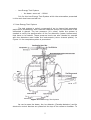
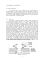
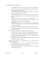
3.1.2 Mass Spectrometer
A quadrupolar mass spectrometer is used as mass filter for the ions.
It allows the selection of ions according to their mass (from 0 – 100 amu).
The mass filter is formed by 4 cylindrical electrodes. The accurate layout of
the rods is really important for a good performance of the device (mass
filtration, stability and sensitivity). A high frequency variable tension and a
constant one are applied to the rods. The oscillation characteristics of the
ions in the electric field will cause that only the ions with the wanted
mass/charge ratio will pass through the filter, while the other ones will be
rejected out of the rods. Figure 3.2 shows a quadrupolar mass
spectrometer.
Figure 3.2 Quadrupolar Mass Spectrometer [2]
10
3.1.3 Ion Detectors
In order to analyze the ions produced by the ion source and selected
by the mass spectrometer, there is the option to send the ion beam to a
detector. In the CESR system there is the possibility to send the ions beam
towards a Faraday detector. The Faraday collector is composed of a circular
disc of conducting material. The ions arrive at this target and transfer their
charges as an electrical current. This current is then amplified by the
system electronics for the processing of the information.
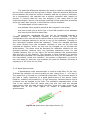
The other trajectory that the ion ray can take is toward the vacuum
chamber where the instrument to be calibrated is placed. If the vacuum is
not low enough there is a high possibility that the ions will not reach the
target due to the high probability of collisions with particles found in their
path. The vacuum should be lower than 1.3 10-6 mbar.
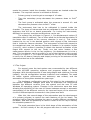
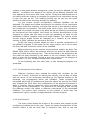
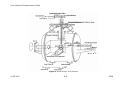
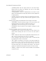
Figure 3.3 shows whole diagram of the system, including the ion
beam, the mass spectrometer and the deflector.
Figure 3.3 Ion Beam System
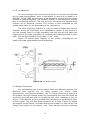
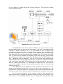
3.2 System Command
For commanding the overall system there are different devices: the
QMS-420 that controls the ion beam system (ion source, mass
spectrometer, and Faraday detector), the TL 78 that controls the motors of
the system, the high voltage source for accelerating the ions and finally an
electronic box that was built for modifying also some variables of the ion
source. These devices work as manual user interfaces for the different parts
of the system. The user has direct access to all of them. Figure 3.4 shows
the system control layout. All these devices are located in a rack of the Low
Energy Test System in the control room. There are also devices controlling
11
the ion detector located inside the vacuum chamber. They are also located
in the command rack.
Figure 3.4 System Control Layout
The QMS-420 is the direct control interface for the ion source. It can
be accessed directly by keys on its front panel, or by a PC connected serially
through a RS232 interface line. It is connected to other systems that
process the signals from the ion beam. These systems are the QMN-112i,
the QME-125 and the EP-112. The QMN-112i amplifies the signals coming
from the QMS-420 and from the system towards the PC through the QME125. It works as an isolated link between these two devices, and provides
an interface decoupled from the ground. It allows potential difference up to
900 V between the two devices. The EP-112 receives and amplifies the
signals produced by the Faraday detector and sends them towards the QME125. And finally the QME-125 produces the signals needed by the source
and the mass spectrometer. The acceleration voltage for the ions that are
sent to the vacuum chamber is controlled manually, with an external high
voltage source [6].
The QMS-420 has a display to show important information on the
status of the system to the user, as well as errors in the system or in its
configuration. With the QMS-420, changes in the current of the filament can
be done, as well as the change on/off to start/stop the ionization of the gas.
As an important feature of the system a scan of the produced ion
beam can be done, yielding the specific content of the ions (elements). The
scan occurs in the Faraday detector. The ion beam goes through the mass
12
spectrometer and then towards the Faraday detector in order to get a scan
of the ray. The system will set the mass spectrometer to filter ions with
different masses, from 0 amu up to a given value according to the scan
routine configuration. The system starts with the lower masses and the
mass range given by the user. This information is processed and sent to the
QMS-420 from where it can be accessed through the RS232 line.
The electronic external box located in the command rack can control
the intensity of the current through the filament, the focus of the ion beam,
the acceleration voltage, the manual/automatic mode, the trajectory of the
ray (ion detector or vacuum chamber), and the motors end position. The
electronic circuit was modified in the first stage of the automation to give
the user the option of having either automatic or manual access to the
system. Its outputs are connected to the PC through a NI (National
Instrument) data acquisition card [9].
The TL 78 is used to generate the power signals needed to control the
electrical motors located in the system. This makes it possible to control 4
motors, the translation ones of the ions beam and the ones located in the
instrument rotation axis. The motor responsible for the motion of the ion
detector inside the vacuum chamber is not controlled by this device, and
furthermore was not automated in this work, so its control device will not be
studied. Each motor can be controlled by complete turns or partial turns.
The console has visualization displays of the positions of the motors, and as
well as the possibility to manually manipulate them. This device can be
manually accessed by the user from its frontal panel or also by a PC
connected in the series RS232 line to the IP28 that directly controls the TL
78. The IP28 works as an interface for the PC, and can also program
routines for the motors [5, 7].
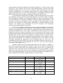
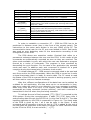
System values can be accessed through two NI cards. In Table 3.1
the input and output variables connected to the PC at each of the different
cards are listed. Note that here output means from the PC towards the
electronic box, and input from the electronic box to the computer. In the
table the value range for each of the variables is presented. According to
the values expected each of the lines were connected to analogue (AI or
AO) or digital (DI and DO) input/output from the NI cards.
Command
Current Emission
Card/Channel
AO 1/1
Focalization
Faraday / Vacuum Chamber
AO 1/0
DO 1/0
End Position of Motors
DO 1/1
Ions Energy
AO 2/0
Trajectory Status
Faraday / Vacuum Chamber
Status Dead End of Motors
AI 1/4
AI 1/2
Table 3.1 Input and Output
13
Range
Input/Output
0 – 1.8 V
Output
(0 – 600 µA)
0–5V
Output
0 – Chamber
Output
1 – Detector
0 – Off
Output
1 – On
0 – 10 V
Output
(0 – 800 eV)
> 4V - Detector
Input
< 4V - Chamber
> 2V Yes
Input
< 2V No
of the NI Acquisition Card
4. LCPB – Logiciel de Commande du Petit Banc
The LCPB software is used to command the test system from a DELL
PC with Windows XP operating system. The software was programmed in
LabWindows/CVI. As mentioned in Section 3.2 connections are done from
COM1 and COM2 to two RS232 cables and also through two NI data
acquisition cards. These connections are for the different system equipment
that control different variables through the user interface.
The LCPB was created because it offers the user a simple working
environment. It allows the user to have easy and direct access to different
main features of the ion source. It produces through the NI acquisition
cards analog command outputs towards the electronic box located in the
rack. And also it writes in the COM1 port towards the QMS-420 in ASCII.
During the development of the project in the CESR the study of the old
version of the LCPB was done and also some modifications. This is
documented in Section 4.1.
After studying the old version of the software, a new independent
version software was created to control different features that were not
incorporated to the previous LCPB version. These features are, as
mentioned before, the movement of four different motors located in the
system for making the displacement of the ion beam on top of the vacuum
chamber, and the instrument located inside the chamber. Refer to Section
4.2 and 4.3 for further information.
Finally the integration of both programs was done and is presented in
Section 4.4.
4.1 LCPB – Previous Version
The LCPB was conceived out of the need for an updated user
interface and a program to control some of the features of the Low Energy
Calibration System. The first stage of the program was able to modify
different variables through the interface between COM1 and both of the NI
acquisition cards connected to an electronic box located in the rack where
different parts of the system were found, to the QMS-420 interface and
directly to the high power supply for the ion source acceleration tension.
The program was developed (on the basis) of the updated software
used several years ago that commanded the QMS-420, but also with the
observation of the data transmitted through the RS232 line using a serial
logic analyzer, that experimentally shows the raw information transmitted
between PC and the QMS-420 [8].
The features that can be modified with the old version of the LCPB
are:
-
Acceleration High Voltage applied to the ions (from 0 to 800 eV)
-
On/off of the filament
-
Current intensity through the filament
-
Beam focus
14
-
Selection of mass species of the ions
-
Trajectory of selected ions towards the Faraday detector or the
vacuum chamber
-
Scan of the ray for determining the elements contained in the ionized
gas
-
Other different options can also be selected
In the interest of the system’s security, the values for the
acceleration voltage of the ions and the current intensity in the filament are
limited in the interface (LCPB) to 800V and 600µA. When turning off the
source, the intensity of the filament needs to be stepped down slowly to a
minimum value (close to 0 A), before the user turns it off completely. The
program displays messages for the user, informing of the system’s status,
i.e., of the beam status and when dysfunctions occur. The software provides
a help document that allows the user to get to learn more about its
functions and how to solve different problems.
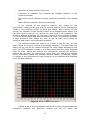
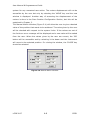
The software allows the user to do a scan of the ion ray. The ion
beam needs to be sent towards the Faraday detector. The mass filter will
select one by one all the masses through the mass range selected by the
user. The LPCB displays a graph in a window that shows the result obtained
from the scan, where the content ions distribution through the different
masses can be seen. By placing the cursor over any part of the plotted
curve, information about the possible element specie is displayed. Figure
4.1 shows a plot obtained from gas ionization in the chamber and detected
in the Faraday detector.
Figure 4.1 Plot of the Ion Ray Scan
A deep study of the old software was done in order to understand the
interaction between the QMS-420 console and the PC. While the
15
programming algorithm was understood, different errors were found in the
code. After a review of the errors and the general performance of the
system, some corrections were recommended and changes were made to
the code in order to improve the system.
This new modifications included changing variable names or values
that were wrong, and are not documented in this report. However,
adjustments made to certain routines which were in need of improvement
are listed below:
-
Enableing/Disabling buttons while
information or performing a task.
the
system
is
processing
-
Enabling the close button for the scan window.
-
Enabling the possibility to start a scan with a zero amu mass.
-
Rectifying boundary conditions for the scan.
-
Erasing functions that were not used when the program is executed.
-
Adjusting the value for the current in the filament.
As this last change was the more important done to the system, the
new algorithm implemented is explained briefly in the next section.
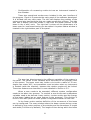
4.1.1 Current in the Filament
The current in the filament, which emits electrons that are
accelerated for producing collisions with the gas in the ionizing chamber,
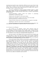
can be modified in the user interface of the LCPB software. In Figure 4.2 the
old and new version of the LCPB Ion Source panel are shown. The sections
for the filament current values are highlighted and discussed next.
As the current in the filament can not exceed 600 µA, special care
must be taken. A limit to the NI card output is set. Another important
consideration that needs to be made while tuning the filament is that only
small changes of current are allowed. If this is not achieved in the long term
the filament can be damaged and its life time reduced.
In the old version of the LCPB the current was modified directly with
one of the output of the NI card. As it can be seen in Figure 4.2 the value
was changed with the help of a knob. The real value of the filament
intensity was displayed in the panel and the user directly modified the
voltage value of the NI card. The voltage from the NI card was electronically
converted to the current intensity in the filament. Due to the delay in the
port communications and the system response, the knob control was
inefficient. The change in the value of the current was slow and the user
could keep modifying the value even thought the updated of the last change
was not displayed on the user screen. This resulted in significant changes of
the values of the current without notice, and long delays in achieving a
desired value. The old version did not have a special feature to protect the
filament from big current changes. Small changes were monitored to be less
than 30% only when the filament was turned off.
16
a)
b)
Figure 4.2 Ion Beam Control Panel for the LCPB. a) Previous Version. B) Version
2007.
In the new version the value that is modified is the current. The real
intensity in the filament is displayed, the desired intensity value can be
entered and the actual voltage written into the NI card is shown. The
voltage feed to the NI card was added to the interface for security reasons,
so the user can make sure that the value in the card not exceeds 1.46 V
(600 µA in the filament).
A different algorithm was developed for adjusting the value of the
current in the filament for any of the different cases (turn on, turn off, value
change). This algorithm is shown in Figure 4.3. As it can be seen boundary
conditions and smooth changes protection were included for protecting the
filament.
It was observed that the relationship between the value of the
filament current and the value of the voltage in the NI card does not remain
the same. It varies according to the number of times that the filament has
been used (wear out) and the period the filament has been turned on
(stabilizing time). This is why in the new approach the previous n-1 and the
actual n current/voltage values are taken to calculate a curve that is used to
obtain the next voltage value (desired) in the NI card to increase/decrease
the filament intensity.
The algorithm was coded and replaced the old one of the previous
version of the LCPB.
17
Figure 4.3 Filament Current Fitting Algorithm.
4.2 IP28 – PC Communication
After becoming familiar with the previous version of LCPB and the
programming software LabWindows/CVI, a new area of the Low Energy Test
System was developed. As stated before, this stage includes the commands
of four of the motors of the system.
Figure 3.4 demonstrates that the TL 78 is connected to the IP28,
which creates a means of communication with the motors. Both of them can
be accessed through their frontal panel or through a PC connected in series
through the RS232 line. The IP28 converts the commands given by the PC
or its frontal panel to signals to turn on/off the feed voltage to the different
motors connected to the TL 78. The motors controlled by the TL 78 are the
linear displacement of the ions beam (x and y) and the angular
displacement of the instrument (α and β).
A study of existing controlling software was necessary to
communicate with the IP28. This software was used to command the IP28
through a PC, and was written in TURBO-PASCAL. Through this research, it
became apparent that ASCII character encoding was required for
communication. Different commands, shown in Table 4.1, were already
saved in the IP28 that recalled different routines for controlling the motors.
Not all the routines recognized by the IP28 were used, and therefore are not
presented in the table. The function of these commands was evaluated
using a serial logic analyzer that also helped to understand the response of
the system to the different commands. These commands were the ones
used for the new software developed subroutines [7].
18
Command
D {motor axis};
M {motor axis};
N {motor
axis}{nnnnnnn};
O {motor axis};
Function
Ask the system the actual position of the motor(s).
Demands the motor(s) to move in relative motion.
Configures the number of step to move in relative motion
for the motor(s) with nnnnnnn from 1-7999999.
Look for the origin position of the motor (s)
Defines the motor(s) speed value for the fast mode
R {motor
configuration [32-4000 impulses per second] with nnnn
axis}{nnnn};
from 32 – 4000
Defines the motor(s) speed value for the slow mode
T {motor
configuration with the period of the motor impulses
axis}{nnnn};
[0.01-50 impulses per second], with nnnn from 2 /9999
period (nnnn times 10 ms)
+ {motor axis};
Defines a positive motion of the motor(s)
- {motor axis};
Defines a negative motion of the motor(s)
?;
Ask for the status of the system
Table 4.1 IP28 Commands Used for the New LCPB.
In order to establish a connection PC – IP28 the IP28 has to be
positioned in distance mode (key in the front of the console panel). The
instructions to the motor were written in the port COM2 of the PC. The
communication baud rate for the PC port was settled to 9600. Odd parity
was used as error detecting code for the transmission according to the
configuration of the IP28.
The IP28 allows two execution modes. Punctual that refers to a
permanent exchange between the user and the IP28. In this mode all the
commands are automatically executed as soon as they are received. The
other mode available is cycle, with which the user can elaborate a program
formed by a series of commands. This program is then executed by
demanding the cycle function. For the case of our application the punctual
mode was used. In addition each sent command is checked for a good
reception during the transmission (character check mode).
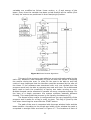
To initiate dialogue PC – IP28 several commands need to be read and
sent from and to the IP28 respectably. When the IP28 is turned on it emits
a signal that states that it is ready to receive data. The PC needs to read
the status of the IP28 to ensure that the console is working properly, and it
will then wait to receive a flawless message.
After this, different configurations of the data lines can be settled. As
a default for our application, the lines were set to: no numeration in lines,
only error codes are used for error detection (no error message is added),
BEEP every time there is an error in the system, data is added when the
commands are being executed (motors position), and each command is
transmitted in the line when they are being executed.
To indicate the end of line/command, [TT] (‘CR LF’) is required by the
IP28 system. During the communication, it adds [TR] (‘CR’) every time it
ends sending data through the RS232 line (in this case to the PC). The data
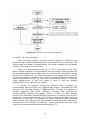
handling algorithm by the IP28 is presented in Figure 4.4. The ready state
of the IP28 is given by the * as it can be seen in the figure. A valid
command and its execution is given by the %, [TR] is added at the end of
the line when the execution of the task is finished. For each instruction send
by the PC to the IP28, it must end with ‘;’ + [TT].
19
Figure 4.4 Data handling algorithm of the IP28.
Every time the IP28 receives and executes commands it checks for
error. If an error is found an error signal will be emitted to the PC. If an
error is detected the IP28 stops receiving commands and executing tasks,
and waits for a special message that states that the problem has been
solve. After receiving the message the IP28 goes to the ready state and
waits for commands. In order to solve the problem, ‘status’ has to be
invoked so the information about the problem can be read and then the
problem needs to be solved. The status is updated every time a command is
executed, so if there is an error, any other right command will reestablish
the 00 error state (no errors).
At the start of the system, default movement variables of the motors
are configured in the system. These are the following:
-
Speed = 2000 impulses/seconds
-
Motor acceleration curve → 400 to 4000 Hz in 300 ms.
-
One turn per motor step.
It was important to understand the relation between distance and
turn of each of the step motors. This was done experimentally for each of
them, and it was found that for the linear motion motors 1 impulse
corresponds to 0.01 mm and for the rotational motion motors 1 impulse
corresponds to 1°.
After understanding the concepts of the communication with the IP28
the program was developed. In the following sections, different parts of the
program are presented, including the algorithms which were necessary for
many important functions within the program.
4.3 Motors Command Software
Two different situations were considered while creating the new
program:
-
Desired to move the beam or the instrument manually to a defined
position, or to bring the motors back to their origin.
20
-
Configuration of a scanning routine to tune an instrument located in
the chamber.
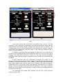
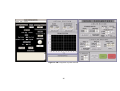
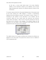
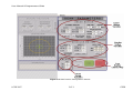
These two operational modes were included in the user interface of
the program. Figure 4.5 presents the main panel of the software developed.
It is divided into two main parts. The left half displays the position of the
motors and also has functions that can make movements of them. This side
also has a display plot that shows in real time the actual position of the
beam in the x and y axis. The right half is where all the parameters of a
beam scan for instrument tuning can be settled. A system status window is
located in the right bottom part of the panel.
Figure 4.5 Main Panel
The user has direct access to the different variables of the system in
the panel. The values of the variables were restricted to the physical limits
of the system. The beam must stay inside a circle with a radius of 32 mm.
Angles can rotate 360°, but precaution must be taken when an instrument
is located inside the chamber, because the rotation angles will be limited.
These two features are described in more detailed in Section 4.3.2.
When a scan needs to be executed, different system configuration
needs to be taken into account. To conduct a scan three main subsystems
variables need to be defined: linear motion, circular motion and the energy
of the beam (added as an extra feature to the program). This division is
found in the main panel to make system configuration easier for the user.
In the linear motion section definition of the movement of the beam
can be configured. The scan window where the beam moves during a scan
is defined by the center position of the window and its dimensions in length
and width (20x20mm by default). The length of time during which the beam
21
remains in the same window throughout a scan can also be defined (10s by
default). In addition, the speed of the motors can be altered. However this
only applies to the motors with linear motion. Finally the waiting position of
the beam while the system is changing the angles of the instrument during
a scan can also be set. This waiting position can be set into the same
position as that of the scanning window (by default).
For the circular motion configuration, different variables can be
adjusted. The angles are limited according to the position of the instrument
and cables inside the chamber, and also the layout of the detectors within
the instrument is important. The start angle (scan origin), the increase of
angle and the number of scans to be done during the scanning process can
be configured for both angles. And finally for further development of the
program an option was left open to have the possibility to allow for the
possibility to define complex routines of angle changes. The velocity of the
circular motion angles cannot be changed, as it remains at the default
velocity of 2000 impulses per second all the time.
Finally the energy section allows the user to set the configuration of
the different energies in the beam for the scan routine. As it can be seen
the first, last and increment value can be modified.
Before launching a scan routine several actions need to be done. The
DRAW PATH button has to be selected, and this will draw the path that the
beam will follow when doing a scan. Then a test needs to be launched to be
sure that the path followed by the beam is the one wanted. After this is
done, a scan can be started. During a scan the motion can be stopped at
any moment. For this, multiple threads were programmed.
In the following part the main task, of the developed program are
presented.
4.3.1 The Movement of the Motors
Different functions were created for setting the variables for the
motion of a motor. Functions for setting the velocity, the number of steps
and the sense of the movement according to the desired position to be
achieved, are programmed within the software. These variables are
calculated within the PC software and then the values are sent by the COM2
port towards the IP28. After the configuration of the desired movement is
done, a function (Move) sends the move command of the motors to the
IP28 with the axis specification. The functions for configuring and moving
the different motors are called in different subroutines of the developed
software. The motors move relatively to the position in which they are
located with a given number of steps towards a certain direction.
4.3.2 Scan Routine
The scan routine starts the motion of the motors with respect to the
configured variables set by the user. Figure 4.6 shows the algorithm of the
function where it can be seen that in hierarchy from first to last the
22
variables are modified as follow: linear motion, α, β and energy of the
beam. Every time the variable has been cycled through all the values (first
till last) the motors are positioned in their start/origin position.
Figure 4.6 Scan Routine Algorithm.
This part of the program was added as an extra thread parallel to the
main one, because it was necessary to give the user the option of stopping
the routine during the scan. In order for the user to be able to stop the
routine it was important that the interface could be accessed by the user all
the times. If the software was structured with only one thread then the
program would only be able to compute one task at a time. So multithreads
were used to have the possibility of having two tasks running at once.
Multiple threads can be executed in parallel on many computer systems. For
the case of a single processor the system switches between different
threads. This means that the process is not literally simultaneous [3].
The thread of the routine is configured from the very beginning of the
program and it waits for a flag in order to start. This flag is given by the
user when launching the scan with the START button.
The path of the scan is computed with the scan window limits and the
beam surface. According to the length and width of the window the path is
computed in straight lines as shown in Figure 4.7. The locations of each of
23
the corners is found for the way forwards and backwards, and then saved
into an array that is called every time the path is scanned. The positions in
the array set the values of the configuration of the lines written to the IP28
that will define the next movement of the motors. After a movement of a
motor the actual position is read so the program checks that the desired
position is achieved.
Figure 4.7 Scan Path Structure
4.3.3 Security Features
If a position needs to be changed a new window opens where the
user can modify any of the motor positions. The option of having direct
access to the position of the motors in the main panel was rejected in order
to protect the system. This decision prevents any undesired movement of
the motors which may have been caused by user errors. The manual motor
motion window is presented in Figure 4.8 a).
a)
b)
Figure 4.8 Manual Motion Panel (a) and Angle Limit Panel (b)
All of the variables of the positions can be modified, without changing
the position of the motor. Motor position limits are established and therefore
the user can not set a lower or higher value. When the desired position is
given then by using the GO button the motors move. To disable the manual
motion the window needs to be close.
Another security feature of the program is the ability to adjust the
angle limits of the rotational motion depending on the instrument located in
24
the chamber. The angles limits are settled in a different window that can be
opened by the user from the main panel. This window is always displayed at
the beginning of the program as a configuration mode of the limits before
any movement of the motors can be allowed. Figure 4.8 b) shows this
window with the different variables that can be modified. After modifying
the maximum and minimum values allowed and closing the window, the
new limits will be displayed in the main panel.
4.4 LCPB – New Version
The integration of the two programs was done to be able to run them
together and be able to get access to all the variables of the overall system
at the same time. The different functions were kept, as well as the main
panels and different sub panels of each of them. They were added together
in the same ‘main’ of the program and the thread for the scan subroutine
was also located inside it.
A start window was designed for the start of the program that shows
the version and the developers of the different stages of the automation
program. The start window is shown in Figure 4.9.
Figure 4.9 Start Window of the LCPB.
Finally the integration of the main panels of each of the two programs
is shown in Figure 4.10.
25
Figure 4.10 Integration System Panels.
26
User Manual & Programmers Guide
5. CONCLUSIONS
The objectives were achieved. The program was tested with different
configurations of the scan routine. The requirements demanded were
achieved. The performance of the system was satisfying, but several
features can still be developed to improve its performance.
One of the main problems that needed to be studied and understood
was the serial communication between ports. Furthermore, it was essential
that port communication was integrated into a system which did not
produce any delay between the command of the user and expected
response. The delays in the non-real time system were of several seconds,
sometimes of just some ms, but this caused problems in the transmission.
While the system was responding for some commands the PC was already
trying to read from the port that was not ready. Delays had to be changed
for reading the lines of the IP28, due to the slow time response of the
motors. A computation of the delay time was integrated to the program,
that according to the distance to be displaced and the motor speed the
delay could vary.
The time consumed for studying the previous version of the LCPB was
longer than expected, mainly because of the lack of a programmer guide of
the algorithms of the program developed by other students. In order to
avoid this same challenge in the future, the new part of the program which
controls the motors was documented, thus making it easier to conduct
updates to the program and improvements to any of the functions.
This is why the new part of the program that controls the motors was
documented in case of that future work wants to be done to the program,
or any improvement that wants to be done to any of the functions.
The study of multithreads and the implementation of one into the
program also took time. It was important to understand the use of different
variables (flags) to turn on/off the parallel thread of the scan routine, in
order to avoid deadlocks. This part of the program can be improved by
adding a thread that will allow the user to abruptly stop the motor at any
moment desired, when any motion of motors is being done.
The development of this program was a major challenge for me.
From a start with a lack of knowledge in several fields of the project, I
ended learning a lot of new concepts that can be applied to different areas
in engineering. It was really interesting to contribute to a project that has
taken several years of different stages.
Further description of the Motors Command Software is included in
the User Manual and Programmers Guide (Annex I).
6. FUTURE WORK
There are two main branches where future work can be done. The
first one is related to the motors command program, where further
development could improve its performance. The main points or areas
where these improvements are recommended are listed below.
-
Implementation of a save configuration that is being used, and
import configuration option from last ones previously used. So if a
calibration is not finished the position and set values for the different
variables can be saved to a configuration file and that will be loaded
back to continue from the stop point.
-
Improve error detection. At the moment the error is only detected at
the start of the program. If any error occurs while using the program
most of the configuration should be reinitialized.
-
Emergency stop at anytime the motors are moving and not only
when the system is doing a scan.
-
When the emergency stop button is used, the motor finishes its
trajectory and then goes to the zero position. Implement the
possibility of stopping the routine at any time and then as desired
start again from the stop position or at the beginning of the routine.
-
Disable the buttons from the IP28 panel when the user is controlling
the motors directly in the user interface from the computer.
-
Routine implementation for several sets of different angle increments
for special layouts in the instrument that wants to be tuned.
The second branch of recommended improvements is related to the
overall system. The work remaining to be done in order to achieve the
complete automation of the system and also to improve features of the
existing one are listed next.
-
Implementation of a program to control the displacement of the ion
detector.
-
In the actual configuration the ion beam is checked sometime to
ensure a good performance of the ion source. This could be done
automatically after a certain number of scans, and saved to memory
so it could be analyzed at the end of the calibration.
-
Save the data from the different values of the system in a
configuration file using a specific format.
-
Understand the oscillation found in the filament current, every time
the current is modified.
-
Save the data when scanning the ions content of the beam.
-
Save values of the variables in the old part of the LCPB in a file, and
then create the possibility of importing them in order to configure the
system.
28
7. GLOSSARY
Ion source: is an electro-magnetic device that is used to create charged
particles.
Rhenium: chemical element with symbol Re and atomic number 75. It is a
transition metal, and it is used in some alloys. Rhenium is obtained as a byproduct of molybdenum refinement and rhenium-molybdenum alloys are
superconducting. It is one of the ten most expensive metals on Earth. It has
one of the highest melting points of all elements, exceeded by only
tungsten and carbon. It is also of the densest, exceeded only by platinum,
iridium, and osmium. Its usual commercial form is a powder. Widely used
as filaments in mass spectrographs and in ion gauges.
Ion: atom or group of atoms, normally electrically neutral, that has lost or
gained one or more electrons. The process of converting electrically neutral
atoms or molecules into ions and the state of being ionized is called
ionization. The recombining of ions and electrons to form neutral atoms or
molecules is called recombination.
Anion: negatively charged ion, which has more electrons in its electrons
shells than it has protons in its nucleus. It is attracted by the anode.
Cation: positively charged ion, which has fewer electrons than protons. It is
attracted by the cathode.
Multi-threading: run multiple computation threads (tasks) in parallel in a
system. Multithreads can be executed in parallel. There exist process
resources sharing but the task are execute independently.
Deadlock: situation wherein two or more competing actions are waiting for
the other to finish, and thus neither ever does.
29
8. REFERENCES
[1] Getting started with
Corporation. February 1998.
LabWindows/CVI.
National
Instruments
[2] LabWindows/CVI user manual. National Instruments Corporation.
February 1998.
[3] Multithreading in LabWindows/CVI. National Instruments Corporation.
July 2003.
[4]Wikipedia, The Free Encyclopedia. http://en.wikipedia.org/wiki/
[5] Micro Contrôle TL 78. Notice d’Utilisation.
[6] Instructions de Service. QMS 420 : Appareil de commande pour
spectromètre de masse quadripolaire. Balzers. Liechtenstein, 1997.
[7] Notice Utilisateur IP28. October, 1984.
[8] BOY, Anne-Laure, GALLAND, Aurélie. Rapport de stage : Interfaçage
d’un banc d’étalonnage de détecteurs de particules embarques sur satellite.
Toulouse, 2005.
[9] BASSAS, Martí. Projet de fin d’études : Etude et modification de
l’électronique de commande d’un banc a vide en vue de son automatisation.
Toulouse, 2005.
[10] DEYINE, Amjad. Rapport de stage : Automatisation de la commande
d’un banc d’étalonnage de détecteurs d’ions embarques sur satellite sous
environnement Labwindows CVI. Toulouse, 2005.
30
User Manual & Programmers Guide
A1. ANNEX I
LCPB – Logiciel de Commande de
la source du Petit Banc
LCPB
USER MANUAL & PROGRAMMERS GUIDE
VERSION - JUNE 2007
Maria Islas
User Manual & Programmers Guide
CONTENTS
•
About This Manual
•
Chapter 1 – Getting Started
•
Chapter 2 – Motors Displacement
•
Chapter 3 – Scan Routine Configuration
•
Chapter 4 – Help / Feature Information
•
Chapter 5 – Programmer Aid Guide
LCPB 2007
A-1
CESR
User Manual & Programmers Guide
About This Manual__________________________
The LCPB User Manual & Programmers Guide is a reference manual that
contains detailed descriptions of LCPB new features and functionality. As an
addition to this manual another document exists, Documentation et Mode
d’emploi du Logiciel de Commande du Petit Banc, for the manipulation of
the previous version software, which features are keep for the July 2007
LCPB version. The user should be familiar with both documents to be able to
operate the overall system.
The LCPB User Manual explains the different tools of the LCPB software to
manipulate the displacement of the system motors, and to configure
different scan routines when tuning space instruments inside the vacuum
chamber. For further information of the software and the test system refer
to the thesis document Study and Automation of a Test System for Space
Instrument Calibration.
This document is divided in five main parts where the LCPB new version
software is documented. Chapter 1 refers to the main steps in order to start
the system and the different options to face possible problems that can be
presented at this stage.
Two different situations were considered while developing the additional
user interaction panel of the LCPB version 2007. The first one includes the
displacement of the beam or the instrument manually to a defined position,
or to their origin. The second one refers to the configuration and launch of a
scanning routine to tune an instrument located in the chamber. These two
operational modes were included in the user interface of the program. This
main panel of the user interface is divided in two main sections that include
all the features for these two operational modes. Chapter 2 gives all the
needed knowledge in order to interact with the main panel section that
deals with the first operation mode (motors movement) mentioned above.
Chapter 3 is related to all the features of the second mode (configuration
and launch of a scanning routine) that are found in the other section of the
panel. Chapter 4 refers to the aids that the software offers to the user while
it is running. Finally, Chapter 5 is a guide for any programmer that needs to
get familiar with the software code in order to do any improvement or
further development to the LCPB 2007 version.
LCPB 2007
A-2
CESR
User Manual & Programmers Guide
______________________________
1
Getting Started
In order to start the software the next options should be fulfill:
-
IP28 should be connected to the COM2 of the PC via a serial RS232
cable.
-
IP28 console must be turned on.
-
TL78 console must be turned on.
-
To avoid errors motors should be in the origin.
-
The IP28 should be set to automatic mode (key on the right side of
the console.
As soon as the LCPB software is started the communication between the PC
and the IP28 is checked. If any communication error is found, a message
will be displayed in the Motors panel and it is recommended to follow the
next steps:
-
Close the LCPB software.
-
Check the serial connection.
-
Check the location of the motors. The location should be a valid
position of the system. If needed the motors should be located in the
origin. The motors can be sent manually to the origin with the aid of
the frontal panel of the IP28.
-
Start again the LCPB software.
The four motors of the system (Figure 1.1) that can be modified by the new
version of the LCPB software are the following:
-
Ion Beam displacement motors: displacement along the x and y axis
of the system. The displacement of these motors is restricted inside a
circle of a radius of 32 mm.
-
Instrument inclination motors: rotation along α and β. The rotation
can be in both directions (clockwise or counter clockwise) a value of
360°. Special care needs to be taken when an instrument is located
in the system due to the cables attached to it. In a scan routine set
LCPB 2007
A-3
CESR
User Manual & Programmers Guide
Figure 1.1 Low Energy Test Systems
LCPB 2007
A-4
CESR
User Manual & Programmers Guide
by the user, α moves small values (scan in the same detection
window of the instrument located in the chamber) and β moves
bigger displacements (access to the different detector windows of the
instrument).
For security reasons the limit of the angle displacements of the system must
be set when starting the LCPB software. A window is automatically
displayed when the software is opened. This window is shown in Figure 1.2.
According to the location of the instrument in the chamber and its
connection cables the user should select the maximum and minimum
ranges where the angles α and β can be moved. By pressing the ‘OK’ key
the limits will be stored in the program. The selected values will be
displayed in the main panel. Future modification of the angle limits can be
accessed from the main panel of the software.
Figure 1.2 Angle Limit Panel
The default values of the system variables when starting the software are
displayed in the main panel. The speed of the motors is set to a default of
2000 impulses/seconds.
LCPB 2007
A-5
CESR
User Manual & Programmers Guide
______________________________
2
Motors Displacement
As mentioned before the motors main panel added to the LCPB software is
divided in two main sections according to the tasks that the users needs
from the system. In this chapter the Motors Displacement Section is
described.
In Figure 2.1 the motors displacement section of the panel is shown, while
the other section is covered. As it can be seen in the figure this section is at
the same time divided in different subsections: Actual Position, Beam
Position and System Status.
The System Status Subsection that is located at the left bottom of the LCPB
panel. In this area, messages are displayed to the user in case of being
needed. When the software is started a ‘SYSTEM IS READY’ message will let
the user know that the system can start to be manipulated. Errors of the
system are also displayed in this area.
The Beam Position Subsection, located in the middle of the Motors
Displacement Section, includes a graph. In this section the actual position of
the ion beam in the system is drawn. This is should help the user to get an
idea of where is the beam (green circle of 10mm radius) with respect to the
system limits (yellow circumference of 32mm radius). Anytime the beam is
moved, the draw of the new position acquired by the beam will be
displayed. Only the final destination of the movement will be shown, i.e.,
not real time drawing is done. At the end of each partial movement (each
motor axis) the actual position is read and displayed in the graph.
The Actual Position Subsection, located at the right top of the panel displays
the real position in millimeters of the motors with respect to the zero of the
system, and gives the user the option of different movements of the
motors.
LCPB 2007
A-6
CESR
User Manual & Programmers Guide
Figure 2.1 Motors Displacement Section
LCPB 2007
A-7
CESR
User Manual & Programmers Guide
This subsection is split in three areas which are explained next. First the
position of the Beam can be found (Figure 2.2). The Beam is located with
respect to the x and y axis of the system. After any movement of the
motors, the position values will be updated. A ‘ZERO SYSTEM’ button can be
press if the beam wants to be sent to the system origin.
Figure 2.2 Beam Position Area
The next area (Figure 2.3) is related to the Instrument location inside the
chamber in relation to the α and β motors angles. As it is done for the
beam, the values of the instrument position are updated every time a
movement has been done. Here the ‘ZERO SYSTEM’ button also sends to
the system origin the angular motors. Be aware that every time the system
is sent to zero it will check if the zero position is located inside the angle
limit ranges. If the zero position is not located within the ranges this
movement will not be allowed.
Figure 2.3 Instrument Position Area
If a desired manual movement wants to be done to the motors, then the
‘MOVE’ key (Figure 2.1) located at the top left of the Motors Displacement
Section should be pressed. This action will open a new window that will
allow the user to manually move the motors of the system. The use of a
separate window for manual displacement of the motors protects the
LCPB 2007
A-8
CESR
User Manual & Programmers Guide
system for any unwanted user action. The motors displacement will not be
accessible by the user but only by selecting the ‘MOVE’ key and the new
window is displayed. Another way of accessing the displacement of the
motors is done in the Scan Routine Configuration Section, but this will be
explained in Chapter 3.
The Manual Motion Window (Figure 2.4) will allow the user to give a desired
value of the position that wants to be achieved. The value given by the user
will be checked with respect to the system limits. If the values are out of
the limits an error message will be displayed and a new value will be asked
from the user. When the values given by the user are correct, the ‘GO’
button will be accessible and by selecting it the beam and the instrument
will move to the selected position. For closing the window, the ‘CLOSE’ key
should be selected.
Figure 2.4 Manual Motion Window
LCPB 2007
A-9
CESR
User Manual & Programmers Guide
______________________________
3
Scan Routine Configuration
The scan routine configuration is done on the right half of the motors panel.
As shown in Figure 3.1 the Scan Routine Configuration Section is divided in
different areas or subsections. To set the parameters of a scan routine,
three main fields must be defined and these can be found in this section:
parameters of the linear motion, parameters of the circular motion and
finally the parameters of the beam energy. At the right button of the panel
the area to launch of the routine is found.
3.1 LINEAR MOTION PARAMETERS
For the linear motion parameters different variables can be modified. These
variables are listed below:
-
Scanning Window
o Center: x and y position of the center of the scanning window.
o Dimension: x and y size of the scanning window, length and
width of the window area.
-
Time Scan: Time that the beam will stay scanning the same scanning
window, following a defined path computed from the scan window
surface.
-
Velocity: Motors speed in any linear displacement. If the speed is
changed this new speed will be used also when a manual movement
of the motors is done.
-
Waiting Position: x and y position of a waiting position while angle
displacements are done to turn the instrument in the chamber.
In addition to these variables which values can be changed according to the
need of the user, different keys are also found in the Linear Motion
Subsection. The different functions of these buttons are explained next.
LCPB 2007
A-10
CESR
User Manual & Programmers Guide
Figure 3.1 Scan Routine Configuration Section.
LCPB 2007
A-11
CESR
User Manual & Programmers Guide
-
GO CENTER: Takes the x and y motors to the defined center position. If
the motors are already located in the center position, no movement will
be done.
-
SET Actual Position as Scan Center: Sets the position where the motors
are located as the center of the scanning window.
-
GO: Takes the motors to the defined waiting position.
-
SET Waiting Position: Sets the actual position of the motors or the
center of the scanning window as the waiting position. This is selected
from the switch located in the right side of the button.
As the user defines these parameters the scanning window is drawn in the
Beam Position Graph, as an aid for the user. It is important to notice that the
size of the window should consider that the center of the beam can not go
further than a circle of 32 mm radius, that it is always displayed in the plot
area. Considering this is needed when defining the scanning window. The beam
will never touch the corners of the scanning window due to its circular form.
3.2 CIRCULAR MOTION PARAMETERS
For the circular motion parameters different variables can be modified. These
variables are listed below:
-
Angle A
o Origin Ao: α start position for a scan routine.
o Step dA: α increment after every linear scan over a determined
scanning window.
o Scan #: number of times the α increment will be done during a
scan routine.
-
Angle B: same as before but applied for the β rotational motor.
-
Angle Limit: This area is only for the display of the angle limits if a
modification of the values wants to be done the ‘MODIFY’ key needs to
be press to display the Angle Limit Window.
In addition to these variables which values can be changed according to the
need of the user, different keys are also found in the Circular Motion
Subsection. The different functions of these buttons are explained next.
LCPB 2007
A-12
CESR
User Manual & Programmers Guide
-
SET Actual Position as Scan Origin: Sets the position where the motors
are located as the origin of the scan routine.
-
ADVANCED CONFIG: Opens a new window where a complex angle step
configuration can be defined (this area needs further development).
-
MODIFY: Opens a new window where the angle limit ranges can be
changed by the user (Refer to Chapter 1).
3.3 BEAM ENERGY
For the beam energy parameters different variables can be modified. These
variables are listed below:
-
First: Sets the value of the energy at the start of the scan.
-
Last: Gives the last energy value that will be achieved at the end of the
scan routine.
-
Step: Gives the energy increment that needs to be done between each
scan subroutine.
Every time a modification to the energy is done the panel of the ion beam
parameters is also updated. At the end of each scan routine the energy goes
back to the first beam energy.
3.4 LAUNCH SCAN ROUTINE
Different keys are available for the user in order to launch or stop a scan
routine. Due to safety reasons, the ‘START’ key is disable until the path follow
for the scan is drawn (press ‘DRAW PATH’) and a test is also run (after drawing
the scan surface press ‘TEST’). This will allow the user to make sure the set
parameters for the linear motion can be done by the system.
After the start of a sequence is done, the ‘STOP’ key becomes available. The
scan routine can be at any time stopped by the user. If the ‘STOP’ key is
selected, the last movement of the motor will be finished and the program will
take the beam to the waiting position, the energy of the beam to the first value
and the instrument to the starting angles.
LCPB 2007
A-13
CESR
User Manual & Programmers Guide
_____________________________
4
Help / Features Information
While using the LCPB new developed panel, direct aid for the user is available.
If the user needs information for any of the features located in the panel, a
right click of the mouse over the feature will display a message with the
specific information of the variable or button selected.
The values of all parameters that can be set by the user are always checked by
the system in order to avoid errors. If a wrong value is introduced an error
message will be displayed and the system will set in the variable the previous
system value. The error message will tell the user the value characteristics
expected for the variable that presents the error. Value limits, number ranges,
system limits are established in software code.
Before any motor displacement is done the system checks the parameters
given by the user to avoid errors. Double or even triple value error check is
done as a protection of the system.
LCPB 2007
A-14
CESR
User Manual & Programmers Guide
______________________________
5
Programmer Aid Guide
This section was thought as an aid for future programmers that will need to get
familiar with the code of the new version of the LCPB added to the previous
version. For basics in the IP28 – PC communication please refer to the Section
4.2 of the thesis document Study and Automation of a Test System for Space
Instrument Calibration. In this Chapter an overall description of the functions
added to the code is included as well as the distribution of the main variables
for the motors.
The IP28 names each of the motors with the next group of variables: W, X, Y
and Z. For simplicity in the new developed software the variables are called as
the scientist at the CESR named them and recognize them. Table 5.1 presents
the correspondence of the variables inside the IP28 with respect to the
variables of the Middle Energy Test System presented in Figure 1.1. The LCPB
code uses the variable names presented in the second column from the table
when interfacing with the user, while it writes and reads from the IP28
(through COM2) with the variable names found on the third column.
System variable
LCPB variable
IP28 variable
X
X
X
Y
Y
Y
α
A
W
β
B
Z
Table 5.1 Correspondence of variables.
The functions developed for the software code are listed below with a brief
explanation of their main tasks. The functions are listed in group according to
their application and in alphabetic order.
-
Functions that QUIT different user interface windows:
o ANGLES: Function that QUITS the panel of angle limits. When
closing it will check if the angles are located inside the limit
LCPB 2007
A-15
CESR
User Manual & Programmers Guide
values, if this is not true an error message will appear and the
user will be ask to set the limits again.
o MANUAL: Function that QUITS the manual move panel. If the
desired positions are not the actual positions of the motors a
warning message will be sent to the user.
o
MOTORS: Function that QUITS the program. It sends the motors
to the origin before closing the program and also close the thread,
of the multi task.
-
Functions that take the motors to the system origin:
o
GOORIGINBEAM: Function that takes the motors X and Y to the
zero position of the system. Sends to zero, saves the values,
displays the value and plots in the graph the new location.
o
GOORIGINSTRUMENT: Function that takes the motors A and B to
the zero position of the system. Sends to zero, saves the values
and displays the value.
-
Functions for the manual motion of the motors (Manual Motion Window):
o
DONEMANUAL: close the Manual Motion Window.
o
GOWANTEDPOSITION: takes the motor to the desired positions.
Checks that the beam stays inside the circle of R=32mm and the
instrument inside the angle range limits.
o
MANUALPOSITION: Opens a panel that lets move the motors to a
desired position.
o
xxxWANTED: Gets the desired position to move the motors.
Checks the position given for the desired position to be inside the
limits (Applies for the four motors).
-
Functions that configure the parameters of the linear motion (Beam
Motion):
o
GOCENTERSCAN: Moves the motor to the Scan Surface Center
configured in the user interface. If the motors are already located
in this position they will not move.
o
GOWAITINGPOSITION: Takes the motors to the waiting scan
position.
LCPB 2007
A-16
CESR
User Manual & Programmers Guide
o
LINEARVELOCITY: Sets the velocity of the motors for the system
for linear motion. Checks the boundary conditions for the velocity
and selects from fast/slow speed.
o
SETCURRENTSCAN: Gets the actual value of X and Y and use it as
the value of the Scan Window Center.
o
SETWAITINGPOSITION: Sets the Actual Position or the Window
Center as waiting point during the rotation of angles in the scan
routine.
o
SIZExxx: Defines the X and Y lengths for the Scan Window.
o
TIMESCAN: Sets the time that the scan will be done in a same
Scan Window before rotating the instrument.
o
WAITINGPOS: Gives the X and Y position for waiting during
rotation of angles in the scan. Checks that the beam stays inside
the circle of R=32mm.
o
xxxCENTER_SCAN: Sets the center position for the Scan Window.
Checks that the beam stays inside the circle of R=32mm (Applies
for X and Y motors).
-
Functions to set the angle limit ranges (Angle Limit Window):
o
SETANGLELIMITS: Sets the value of the angles and goes back to
the main panel. Check parameters so they stay inside the limits.
o
xxxLIMIT: Gives the MAX and MIN limits for the displacements of
each angle. (Applies for A and B)
o
xxxMINMAX: Gets the value for the maximum and minimum angle
for the scan routine for A and B.
-
Functions
that
configure
the
parameters
of
the
circular
motion
(Instrument Motion):
o
ADVANCEDCONFIG: To configure a routine with different angle
steps for different sectors (Not developed yet).
o
SETCURRENTORIGIN: Gets the actual position and use it as the
scan origin for A and B.
LCPB 2007
A-17
CESR
User Manual & Programmers Guide
o
xxxORGIN_SCAN: Sets the angle position for the Scan Origin.
Checks that the values are between the limit of the angles
(Applies for A and B motors).
o
xxxSCANNUMBER: Number of displacements to be done in each
angle. Check parameters so they stay inside the limits (Applies for
A and B motors).
o
xxxSTEP: Gives the increment value of the angle during the scan.
Check parameters so they stay inside the limits (Applies for A and
B motors).
-
Functions that configure the parameters of the energy in the beam:
o
FIRSTENERGY: Sets the starting energy for the scan routine, and
sends the value to the system to adjust the energy on it.
o
LASTENERGY: Sets the last energy for the scan routine.
o
STEPENERGY: Sets the step for the increase in energy for each
subroutine.
-
Functions to prepare, launch and stop the scan routine:
o
DRAWSCAN: Gets the path and simulates the scan. Needs to be
launch before starting the scan to be sure the scan path is
correct.
o
START: Starts the Scan with the parameters determined by the
user. It calls a thread where the routine is computed.
o
STOP: Emergency stop during the scan routine. It sends the flag
for stopping the routine in the thread.
o
TEST: Makes a simulation of the path of the beam through the
scan window (x and y direction). Moves the beam from the actual
position to the waiting scan and then starts the scan. At the end
the beam goes back to the waiting scan position. This function
needs to be used before being able to launch a full scan routine.
o
THREAD_1: Waits for the launch routine variable to be activated
to start the cycle.
LCPB 2007
A-18
CESR
User Manual & Programmers Guide
-
Other functions:
o
CHECKANGLELIMIT: Checks that the angle parameters for the
scan routine remain inside the angle limits settle by the user.
o
DRAWPOINT: Draws the position of the beam in the x/y graph.
o
DRAWSCANPATH: Draws the trajectory that the beam will follow
through the scan window.
o
DRAWSCANSURFACE: Draws in the graph the scanning window.
o
GETPOSITION: Asks the interface for the position of certain
motor.
o
GETSCANSURFACE: Gets the values of the corner of the scanning
window.
o
GOPOSITION: Takes motor X and Y to a desired position. Checks
which motor to move first so it does not go out of the limited
circle of R=32mm.
o
MOVE: Writes to the console to move the motor with certain axis.
The parameters of the motion were already defined by the other
function.
o
READPORT: Reads from the port COM2 the waiting message,
takes the needed part of the line, and trashes the other remaining
part.
o
SCANNINGPATH: Gets the trajectory to follow for the x/y motion.
o
SEARCHORIGIN: Looks for the axis origin of the required motor.
o
SETPARAMETERS: Configures the parameters of motion. Writes to
the console the direction and number of steps a motor with
certain axis should move.
o
LCPB 2007
SETVELOCITY: Sets the velocity of the motion.
A-19
CESR