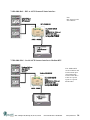
1
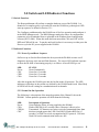
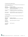
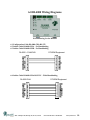
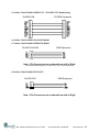
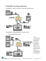
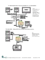
DL4000 User’s Guide Revision 1.03 – May 22, 2013 Equustek Solutions, Inc. Suite 286, 5489 Byrne Rd. Burnaby, BC, Canada V5J 3J1 Toll Free: 888-387-3787 http://www.equustek.com Table of Contents 1.0 DL4000 General Operation & Applications ........................................................................... 3 2.0 Hardware Specifications .......................................................................................................... 4 2.1 Operating Specifications: ................................................................................................................. 4 2.2 Physical Specifications: .................................................................................................................... 4 3.0 DL4000-Hardware Layout....................................................................................................... 5 4.0 Mode of Operation ................................................................................................................... 6 4.1 Online Mode of Operation ............................................................................................................... 6 4.2 Offline Mode ..................................................................................................................................... 6 4.3 BIOS Manager Options.................................................................................................................... 7 5.0 Switch and LED Indicator Functions ..................................................................................... 8 5.1 Switch Functions ............................................................................................................................... 8 5.2 Indicator Functions .......................................................................................................................... 8 5.2.1 Power-Up and Reset Sequence.................................................................................................................8 5.2.2 Normal On-line Operation .......................................................................................................................8 5.2.3 On-Line, Power-Up and Reset Errors.....................................................................................................9 5.2.4 Off-Line Modes .........................................................................................................................................9 6.0 DL4000 Wiring Diagrams ..................................................................................................... 10 6.1 Configuration Cable DL4000-CHA RS-232 ................................................................................. 10 6.2 Online Cable DL4000-CHA – No Handshaking .......................................................................... 10 6.3 Online Cable DL4000-CHB – No Handshaking .......................................................................... 10 6.4 Online Cable DL4000-CHA RS-232C – With Handshaking ...................................................... 10 6.5 Online Cable DL4000-CHB RS-232 – With RTS/CTS Handshaking ........................................ 11 6.6 Online Cable DL4000-CHA RS422/RS485 ................................................................................... 11 6.7 Online Cable DL4000-CHB RS422/RS485 ................................................................................... 11 6.8 Online Cable DL4000-CHC RS232 ............................................................................................... 11 7.0 DL4000 Networking Applications ......................................................................................... 12 7.1 DL4000-DFX – Two DF1 serial devices to a PLC/SLC CH0 or DF1 port ................................ 12 7.2 DL4000-DMX – Modbus Master/Slave to interface to DF1 ....................................................... 12 7.2.1 DMX Modbus Master Mode ..................................................................................................................12 7.2.2 DMX Modbus Master Mode using MODBUS PLUS VIA BM85 BRIDGE ......................................13 7.3 DL4000-MMX – Modbus RTU Slave to Modbus ASCII Master interface ............................... 13 7.4 DL4000-DAS – DF1 to ASCII Scanner/Printer interface ........................................................... 14 7.5 DL4000-MAS – Serial ASCII Scanner interface to Modbus RTU ............................................. 14 #286 – 5489 Byrne Rd, Burnaby, BC, V5J 3J1, Canada Phone: 888-387-3787 or 604-266-8547 www.equustek.com 2 1.0 DL4000 General Operation & Applications The DL4000 hardware platform was designed to be used as a smart Serial to Serial converter. It comes in a DC powered Din-Rail Mountable compact cabinet for ease of portability and installation. Standard protocols such as Modicon Modbus and Allen-Bradley’s DF1 exist already. Other protocols and operations are easily programmed per customer’s requests. The DL4000 has three serial channels, CHA, CHB, and CHC for intermixing protocols and communication standards. RS232C, RS422 and RS485 are available on CHA and CHB, while CHC only does RS232. Configuration of the operating parameters is done quickly and easily by the DL32 V3.X for all DL4000 models except DL4000-DMX use EQ32, both EQ32 and DL32 are windows based software shipped with the unit or available on the Equustek Website. Currently there are five standard DL4000 products available and many other customized ASCII protocol interfaces have been done. Contact Equustek Solutions to see if the DL4000 is the correct device for your communication needs. The DL4000-DMX is a two port device that bridges your Modicon Modbus devices to ones using the DF1 protocol. The DMX can either be used as Modbus Master or Slave as well as having both Modbus ASCII and RTU protocols. The DL4000-DFX is a three port DF1 device. This will allow Two DF1 devices to talk to one CH0 of a PLC or SLC. The ability to intermix Half-Duplex and Full Duplex, or RS232 and RS422 greatly improves the effectiveness of the PLC’s CH0 programming port. The DL4000-MMX allows Modbus RTU devices to communicate with multiple Modbus ASCII devices. The DL4000-DAS interfaces Serial ASCII devices (Scanners/Printers) to A-B's DF1 protocol. The DL4000-MAS interfaces Serial ASCII Scanners to Modicon’s Modbus Protocol. The DL4000-MAS acts as a Modbus Master device and writes the ASCII data to a specific register in a specified slave device. #286 – 5489 Byrne Rd, Burnaby, BC, V5J 3J1, Canada Phone: 888-387-3787 or 604-266-8547 www.equustek.com 3 2.0 Hardware Specifications The DL4000 Hardware Platform has the following specifications. 2.1 Operating Specifications: CHA and CHB have full RS232C, as well as both RS422 4 wire and RS485 2 wire modes. Both channels have the ability of being configured with asynchronous speeds upto 230.4 KBaud CHC has a 3 wire RS232 interface (TX, RX, GND) and is capabable of speeds upto 38.4 KBaud Currently DF1, Modbus, and ASCII are the supported protocols. Custom ones are easily implemented. Both CRC 16 and BCC error checking can be implemented; custom error checking can be added at the customer’s request. Simple Parameter Configuration using menu driven Windows (95/98/ME/XP/NT/2000) based Program via RS-232 Cable. Configuration and Reset Pushbuttons to setup online configuration parameters and do a full Hardware Reset Operating Parameters are stored in Non-Volatile Serial EEPROM The DL4000 uses FLASH upgradeable firmware from the configuration Software. Bi-Color (Green/Red) LED’s for each communication channel indicates activity and status. Green POWER LED indicates power on. 2.2 Physical Specifications: Dimensions: 1.2" H x 4.75" D x 3.2" W (30.4 x 120.7 x 81.3 mm) - Weight 0.56 Lbs (0.2 Kg) Installation: Metal Enclosure; Desktop, # 8 Bolts, or Din Rail Mounting Operating Environment: 32 to 122 °F (0 to 50 °C) Storage: -40 to 185°F (-40 to 85°C) Humidity: 5% to 95% non-condensing Power: 9-27V DC - 1.8 Watts #286 – 5489 Byrne Rd, Burnaby, BC, V5J 3J1, Canada Phone: 888-387-3787 or 604-266-8547 www.equustek.com 4 3.0 DL4000-Hardware Layout This Section contains information of the physical position and purpose of the components of the DL4000. The top row contains the following connectors. Going left to right. 2 pin Power Connector CHA RS422 and RS485 4 pin Screw terminal (Phoenix Type) CHC RS232 3 pin Screw terminal (Phoenix Type) CHB RS422 and RS485 4 pin Screw terminal (Phoenix Type) The LED’s are on the left side going CHA to Power from top to bottom. The RESET pushbutton is on the left side, the Configure pushbutton is on the right side. The bottom side of the DL4000 has the following connectors: Going Left to Right. 9 Pin DM9M connector for CHA RS232C communications 9 Pin DM9M connector for CHB RS232C communications #286 – 5489 Byrne Rd, Burnaby, BC, V5J 3J1, Canada Phone: 888-387-3787 or 604-266-8547 www.equustek.com 5 4.0 Mode of Operation 4.1 Online Mode of Operation Online Mode is the normal operating Mode of the DL4000. In this mode the Channels are now configured as they are defined by the configuration and the DL4000 Model. The DL4000 is ready to interface your equipment. The Reset pushbutton automatically puts the DL4000 into Online mode. 4.2 Offline Mode Once the Configure Pushbutton is pressed the Offline BIOS Manager is started. Using either the configuration software and the “DL Offline Manager” option or a Windows Hyper Terminal type program with com port settings of 9600 Baud, 8,N,1 and Xon/Xoff flow control. BIOS MANAGER for DL4000 - Ver 4.00 Nov 29,01 (c) Equus Technologies. 2001 MAIN MENU 1 - Restore EEPROM to Factory settings 2 - WRITE new Firmware 3 - Memory DUMP 4 - OFF-LINE Diagnostics 5 - DEBUG Mode 6 - FIRMWARE Version 7 - ONLINE MAKE SELECTION (1-7) – #286 – 5489 Byrne Rd, Burnaby, BC, V5J 3J1, Canada Phone: 888-387-3787 or 604-266-8547 www.equustek.com 6 4.3 BIOS Manager Options 1. Restore EEPROM to factory settings Once pressed you will be asked “Restore EEPROM to defaults (Y/N)?” If the answer is “Y”es then the Online parameters will be reset to defaults of Address 1, and settings of 9600,N,8,1 on each communication channel. 2. Write New Firmware Once pressed the message “This *WILL* overwrite DATALINK system code enter (Y/N) to proceed” will be displayed. Hit “Y” and the next message will appear telling you that it is alright to send the new firmware to the Flash; ERASING FLASH, PLEASE WAIT... SEND FIRMWARE TEXT FILE NOW... Once the message to send the firmware appears then either click on the “Burn Flash System File” button to select the .txt file to send, or send the Text File under HyperTerminal. Wait for an “*A-OK* BURN COMPLETE!” message to appear. 3. Memory Dump This is used to display the RAM memory of the DL4000. This should only be done after contacting Equustek Solutions to debug problems. 4. Off-Line Diagnostics Starts a series of tests to test the DL4000’s hardware and should only be done if instructed so by a trained person. 5. Debug Mode Starts up a DL4000 internal Debug mode that can be used by trained personnel to debug problems and check hardware configuration and operation. 6. Firmware Version Once selected the current DL4000 model and version numbers will be displayed. Can be used to check the correct firmware was burnt into the Flash or if the DL4000 has the most up to date firmware in the Flash. 7. Online Does a soft “software” reset of the unit to put it online. #286 – 5489 Byrne Rd, Burnaby, BC, V5J 3J1, Canada Phone: 888-387-3787 or 604-266-8547 www.equustek.com 7 5.0 Switch and LED Indicator Functions 5.1 Switch Functions The Reset pushbutton will perform a complete hardware reset of the DL4000. It is identical to a complete power cycle and will cause the DL4000 to go through its LED start-up sequence as defined in Section 5.2.1. The Configure pushbutton takes the DL4000 out of On-Line operation mode and puts it in the BIOS Manager mode. The BIOS Manager mode also allows for configuration parameters to be downloaded from or uploaded to the Windows based configuration software (DL32-4000). When this mode has been entered the CHA and CHC will be RED and CHB will be out. To put the unit back On-line it is necessary to either press the Reset or cycle the DC power supplied to the DL4000. 5.2 Indicator Functions 5.2.1 Power-Up and Reset Sequence On Power-up or after the Reset button has been pressed the DL4000 executes a self diagnostic check-up or the ram and flash firmware. The correct LED indicator sequence to show the DL4000 is functioning properly is as follows: After all LEDS go out. LED Power CHC CHB CHA STATUS Green Continuously Green for 0.5 seconds Green for 0.5 seconds Green for 0.5 seconds After this sequence the DL4000 goes into the On-line mode of Operation. The LED indicators will behave in the certain way defined by the DL4000 model used. Most likely all LEDS will be off waiting for communication on its channels. 5.2.2 Normal On-line Operation The following is a description of the normal operation of the Channel Leds on the DL4000. Custom products operation will differ than the following: LED Power CHA, CHB, & CHC Description of Operation Green Indicates Power is being supplied to the DL4000. Flashes GREEN for 0.5 seconds when a Character is Received or Transmitted. If Characters are being received of transmitted faster than this then it might appear the LED is on SOLID. Flashes RED for 0.5 seconds if a NAK is received or transmitted in DF1 protocol. Will also flash if all serial communication buffers are full. #286 – 5489 Byrne Rd, Burnaby, BC, V5J 3J1, Canada Phone: 888-387-3787 or 604-266-8547 www.equustek.com 8 5.2.3 On-Line, Power-Up and Reset Errors The following table describes the meaning of LED patterns if the internal diagnostic tests detect an error on Reset/Power-Up. LED Pattern Description of Problem CHA, CHB, & CHC The flash has not be burnt properly and the A-OK was not Flashing RED transmitted. Please reburn the flash with the correct text file. Contact Customer Support for help. CHA, CHB, & CHC The BIOS has been corrupted. A new Flash Chip has to Solid RED be supplied by the factory. Please contact Customer support. Start-up Sequence keeps repeating. The DL4000 EEPROM is corrupt.. Please Restore to Factory Settings (See Section 4.3) and then reconfigure the unit. 5.2.4 Off-Line Modes The following table describes the meaning of LED patterns in the different Off-Line modes of operation. LED Pattern CHA & CHC Solid RED Description of Operation BIOS Manager/Configuration Parameter Download/Upload CHA & CHC Solid Green CHB Solid Red Offline Hardware Diagnostics Testing Mode CHA Solid Red CHB & CHC Solid Green Offline Debug Mode #286 – 5489 Byrne Rd, Burnaby, BC, V5J 3J1, Canada Phone: 888-387-3787 or 604-266-8547 www.equustek.com 9 6.0 DL4000 Wiring Diagrams Pin Numbering for the DL4500 6.1 Configuration Cable DL4000-CHA RS-232 6.2 Online Cable DL4000-CHA – No Handshaking 6.3 Online Cable DL4000-CHB – No Handshaking DL4000 – CHA/CHB PC/OEM Equipment 6.4 Online Cable DL4000-CHA RS-232C – With Handshaking DL4000-CHA #286 – 5489 Byrne Rd, Burnaby, BC, V5J 3J1, Canada PC/OEM Equipment Phone: 888-387-3787 or 604-266-8547 www.equustek.com 10 6.5 Online Cable DL4000-CHB RS-232 – With RTS/CTS Handshaking DL4000-CHB PC/OEM Equipment 6.6 Online Cable DL4000-CHA RS422/RS485 6.7 Online Cable DL4000-CHB RS422/RS485 DL4000-CHA/CHB OEM Equipment Note: 4 Pin Connectors are numbered from Left to Right For two wire RS485 Jumper Pins 1-2 and 3-4 for - and + wires respectively 6.8 Online Cable DL4000-CHC RS232 DL4000-CHC OEM Equipment Note: 3 Pin Connectors are numbered from Left to Right #286 – 5489 Byrne Rd, Burnaby, BC, V5J 3J1, Canada Phone: 888-387-3787 or 604-266-8547 www.equustek.com 11 7.0 DL4000 Networking Applications 7.1 DL4000-DFX – Two DF1 serial devices to a PLC/SLC CH0 or DF1 port 7.2 DL4000-DMX – Modbus Master/Slave to interface to DF1 7.2.1 DMX Modbus Master Mode NOTE: The Modbus Master can communicate with any Slave device on the Modbus Slave network and any devices capable of receiving PLC5 message commands. Modbus and DF1 addresses must not be duplicated (convert to the same radix) or the Master will receive two responses. The DL4000 can be any station number on DF1 including Station 00 (not used on Modbus). #286 – 5489 Byrne Rd, Burnaby, BC, V5J 3J1, Canada Phone: 888-387-3787 or 604-266-8547 www.equustek.com 12 7.2.2 DMX Modbus Master Mode using MODBUS PLUS VIA BM85 BRIDGE NOTE: PLCs and HMIs etc. on Modbus Plus can be programmed to communicate with PLC5s, SLC5/04s and HMIs on DF1, i.e. any devices capable of handling PLC-5 DF1 message commands. 7.3 DL4000-MMX – Modbus RTU Slave to Modbus ASCII Master interface Note: Modbus RTU Network could also be RS422/485 and Modbus ASCII network could be RS232. #286 – 5489 Byrne Rd, Burnaby, BC, V5J 3J1, Canada Phone: 888-387-3787 or 604-266-8547 www.equustek.com 13 7.4 DL4000-DAS – DF1 to ASCII Scanner/Printer interface Note: DF1 Network could also be RS232. 7.5 DL4000-MAS – Serial ASCII Scanner interface to Modbus RTU Note: Modbus RTU can also be RS232 and ASCII Scanner input can be RS422/485. ASCII scanner data is written to a specific register in a specific Modicon PLC. #286 – 5489 Byrne Rd, Burnaby, BC, V5J 3J1, Canada Phone: 888-387-3787 or 604-266-8547 www.equustek.com 14