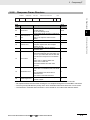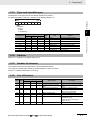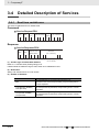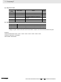
1
Cat. No. S103-E1-01 KP_G-OD-_ KP_L-OD-_ Grid Connect Photovoltaic Inverter COMMUNICATION MANUAL 1 Grid Connect Photovoltaic Inverter KPG/KPL Communication ManualGrid Connect Photovoltaic Inverter KPG/KPL Communication Manual Introduction 4 1-1 Introduction . . . . . . . . . . . . . . . . . . . . . . . . . . . . . . . . . . . . . . . . . . . . . . . . . . 1-2 1-2 Read and Understand This Manual . . . . . . . . . . . . . . . . . . . . . . . . . . . . . . . 1-3 Grid Connect Photovoltaic Inverter KPG/KPL Communication Manual 1-1 1 Introduction 1-1 Introduction Thank you for choosing the KPG or KPL (hereafter described KP inverter) Grid Connect Photovoltaic Inverter. This communication manual describes essential information regarding communication of the KP inverter. The KP inverter is designed for use in Grid Connect Solar Systems. The installation must always be carried out by qualified personnel with knowledge of electrical systems and according to national standards for electrical installations. • This communication manual is intended for Users and Installers of the KP inverter. • Read this manual carefully and make sure that you understand it well to ensure that you are using the communication of KP inverter. • Keep this manual in a safe location so that it is available for reference when required. • For detail description such as function, performance, and usage of the KP inverter, refers to the manual of the KP inverter. 1-2 Grid Connect Photovoltaic Inverter KPG/KPL Communication Manual 1 Introduction Read and Understand This Manual Read and understand this manual before using the KP inverter. Please consult your OMRON representative if you have any questions or comments. 1-2 Read and Understand This Manual 1-2 Warranty and Limitations of Liability 1 WARRANTY OMRON's exclusive warranty is that the products are free from defects in materials and workmanship for specified period from date of sale by OMRON. OMRON MAKES NO WARRANTY OR REPRESENTATION, EXPRESS OR IMPLIED, REGARDING NON-INFRINGEMENT, MERCHANTABILITY, OR FITNESS FOR PARTICULAR PURPOSE OF THE PRODUCTS. ANY BUYER OR USER ACKNOWLEDGES THAT THE BUYER OR USER ALONE HAS DETERMINED THAT THE PRODUCTS WILL SUITABLY MEET THE REQUIREMENTS OF THEIR INTENDED USE. OMRON DISCLAIMS ALL OTHER WARRANTIES, EXPRESS OR IMPLIED. LIMITATIONS OF LIABILITY OMRON SHALL NOT BE RESPONSIBLE FOR SPECIAL, INDIRECT, OR CONSEQUENTIAL DAMAGES, LOSS OF PROFITS OR COMMERCIAL LOSS IN ANY WAY CONNECTED WITH THE PRODUCTS, WHETHER SUCH CLAIM IS BASED ON CONTRACT, WARRANTY, NEGLIGENCE, OR STRICT LIABILITY. In no event shall the responsibility of OMRON for any act exceed the individual price of the product on which liability is asserted. IN NO EVENT SHALL OMRON BE RESPONSIBLE FOR WARRANTY, REPAIR, OR OTHER CLAIMS REGARDING THE PRODUCTS UNLESS OMRON'S ANALYSIS CONFIRMS THAT THE PRODUCTS WERE PROPERLY HANDLED, STORED, INSTALLED, AND MAINTAINED AND NOT SUBJECT TO CONTAMINATION, ABUSE, MISUSE, OR INAPPROPRIATE MODIFICATION OR REPAIR. Grid Connect Photovoltaic Inverter KPG/KPL Communication Manual 1-3 1 Introduction Application Considerations SUITABILITY FOR USE OMRON shall not be responsible for conformity with any standards, codes, or regulations that apply to the combination of products in the customer's application or use of the products. At the customer's request, OMRON will provide applicable third party certification documents identifying ratings and limitations of use that apply to the products. This information by itself is not sufficient for a complete determination of the suitability of the products in combination with the end product, machine, system, or other application or use. The following are some examples of applications for which particular attention must be given. This is not intended to be an exhaustive list of all possible uses of the products, nor is it intended to imply that the uses listed may be suitable for the products: • Uses involving potential chemical contamination or electrical interference, or conditions or uses not described in this manual. • Nuclear energy control systems, combustion systems, railroad systems, aviation systems, medical equipment, amusement machines, vehicles, safety equipment, and installations subject to separate industry or government regulations. • Systems, machines, and equipment that could present a risk to life or property. Please know and observe all prohibitions of use applicable to the products. NEVER USE THE PRODUCTS FOR AN APPLICATION INVOLVING SERIOUS RISK TO LIFE OR PROPERTY WITHOUT ENSURING THAT THE SYSTEM AS A WHOLE HAS BEEN DESIGNED TO ADDRESS THE RISKS, AND THAT THE OMRON PRODUCTS ARE PROPERLY RATED AND INSTALLED FOR THE INTENDED USE WITHIN THE OVERALL EQUIPMENT OR SYSTEM. 1-4 Grid Connect Photovoltaic Inverter KPG/KPL Communication Manual 1 Introduction 1-2 Read and Understand This Manual Disclaimers PERFORMANCE DATA Performance data given in this manual is provided as a guide for the user in determining suitability and does not constitute a warranty. It may represent the result of OMRON's test conditions, and the users must correlate it to actual application requirements. Actual performance is subject to the OMRON Warranty and Limitations of Liability. CHANGE IN SPECIFICATIONS 1 Product specifications and accessories may be changed at any time based on improvements and other reasons. Consult with your OMRON representative at any time to confirm actual specifications of purchased product. DIMENSIONS AND WEIGHTS Dimensions and weights are nominal and are not to be used for manufacturing purposes, even when tolerances are shown. ERRORS AND OMISSIONS The information in this manual has been carefully checked and is believed to be accurate; however, no responsibility is assumed for clerical, typographical, or proofreading errors, or omissions. PROGRAMMABLE PRODUCTS OMRON shall not be responsible for the user's programming of a programmable product, or any consequence thereof. COPYRIGHT AND COPY PERMISSION This document shall not be copied for sales or promotions without permission. This document is protected by copyright and is intended solely for use in conjunction with the product. Please notify us before copying or reproducing this document in any manner, for any other purpose. If copying or transmitting this document to another, please copy or transmit it in its entirety. Grid Connect Photovoltaic Inverter KPG/KPL Communication Manual 1-5 1 Introduction 1-6 Grid Connect Photovoltaic Inverter KPG/KPL Communication Manual Contents Chapter 1 Introduction ....................................................................... 1-1 1-1 Introduction............................................................................................................................ 1-2 1-2 Read and Understand This Manual...................................................................................... 1-3 Chapter 2 Settings .............................................................................. 2-1 2-1 Outline of communications functions ................................................................................. 2-2 2-2 Cable Connections ................................................................................................................ 2-2 2-3 Communications settings..................................................................................................... 2-3 2-3-1 Communication settings for KP40G ............................................................................ 2-3 2-3-2 Communication settings for KP100G .......................................................................... 2-3 2-3-3 Communication settings for KPooL ............................................................................. 2-4 Chapter 3 Compoway/F...................................................................... 3-1 3-1 CompoWay/F Communications Specifications .................................................................. 3-2 3-2 Frame Formats....................................................................................................................... 3-3 3-2-1 Command Frame structure ......................................................................................... 3-4 3-2-2 Response Frame Structure ......................................................................................... 3-5 3-3 FINS-mini................................................................................................................................ 3-6 3-3-1 PDU Formats............................................................................................................... 3-6 3-3-2 Variable Areas ............................................................................................................. 3-6 3-3-3 Type code (variable type) ............................................................................................ 3-7 3-3-4 Address ....................................................................................................................... 3-7 3-3-5 Number of elements .................................................................................................... 3-7 3-3-6 List of Services ............................................................................................................ 3-7 3-4 Detailed Description of Services.......................................................................................... 3-8 3-4-1 Read from variable area.............................................................................................. 3-8 3-4-2 Composite read from variable area (KPooL only) ..................................................... 3-11 3-4-3 Read Controller information ...................................................................................... 3-13 3-4-4 Read Controller Attributes ......................................................................................... 3-14 3-4-5 Read Controller Status .............................................................................................. 3-15 3-4-6 Echoback Test ........................................................................................................... 3-19 3-4-7 Operation Command ................................................................................................. 3-20 3-4-8 Read character string area........................................................................................ 3-21 3-5 Response Code List ............................................................................................................ 3-22 Chapter 4 MODBUS ............................................................................ 4-1 4-1 MODBUS Communications Specifications ......................................................................... 4-2 4-2 Frame Formats....................................................................................................................... 4-3 4-2-1 Command Frame structure ......................................................................................... 4-3 4-2-2 Response Frame Structure ......................................................................................... 4-5 4-3 Function Codes ..................................................................................................................... 4-6 4-4 Variable Areas........................................................................................................................ 4-7 4-4-1 Addresses ................................................................................................................... 4-7 Grid Connect Photovoltaic Inverter KPG/KPL Communication Manual 1 4-4-2 4-4-3 4-5 Chapter 5 5-1 2 Number of Elements.................................................................................................... 4-7 Communications Data ................................................................................................. 4-7 Detailed Description of Services.......................................................................................... 4-8 4-5-1 Multiple Read from Variable Area................................................................................ 4-8 4-5-2 Single Write to Variable Area....................................................................................... 4-9 Communications Data ...................................................... 5-1 Variable Area (Setting Range) List ....................................................................................... 5-2 Grid Connect Photovoltaic Inverter KPG/KPL Communication Manual 2 Settings This section describes the settings of communications by the KP inverter. 4 2-1 Outline of communications functions . . . . . . . . . . . . . . . . . . . . . . . . . . . . . 2-2 2-2 Cable Connections . . . . . . . . . . . . . . . . . . . . . . . . . . . . . . . . . . . . . . . . . . . . . 2-2 2-3 Communications settings . . . . . . . . . . . . . . . . . . . . . . . . . . . . . . . . . . . . . . . 2-3 2-3-1 2-3-2 2-3-3 Communication settings for KP40G . . . . . . . . . . . . . . . . . . . . . . . . . . . . . . . . . 2-3 Communication settings for KP100G . . . . . . . . . . . . . . . . . . . . . . . . . . . . . . . . 2-3 Communication settings for KPooL . . . . . . . . . . . . . . . . . . . . . . . . . . . . . . . . . 2-4 Grid Connect Photovoltaic Inverter KPG/KPL Communication Manual 2-1 2 Settings 2-1 Outline of communications functions The KP inverter are equipped with an RS232C/RS-485 port, which allows remote monitoring and remote operations over networks. The following protocol is supported: Model KPG Suported protocol Compoway/F KPL Compoway/F, MODBUS The KP inverter has the following communications functions: Reading settings and data Executing operation commands CompoWay/F is OMRON's unified communications protocol for general-purpose serial communications. This unified format has a proven track record with OMRON Programmable Controllers, has FINS-compliant commands (see note), and simplifies communications between the host computer and components. Note: FINS (Factory Interface Network service) is a messaging protocol for communications between Controllers in OMRON FA networks. Modbus is a standard communications control method that conforms to the Modicon Company’s RTU-mode Modbus Protocol (PI-MBUS-300 Revision J). Supports functions are similar to the CompoWay/F Read Variable Area, Write Variable Area, Operation Command. 2-2 Cable Connections Refer the manual of each inverter for cable connections. 2-2 Grid Connect Photovoltaic Inverter KPG/KPL Communication Manual 2 Settings 2-3-1 2-3 Communications settings 2-3 Communications settings Communication settings for KP40G Communication protocol settings You can use only Compoway/F on KP40G. There is no setting for communication protocol. 2 2-3-1 Communication settings for KP40G Node number (Unit number) settings Node number can be set by setting switch as shown figure. Baud rate settings Baud rate is fixed 19200bps. 2-3-2 Communication settings for KP100G Communication protocol settings You can use only Compoway/F on KP100G. Always set TYPE1 as protocol on communication settings menu of Data Logger. Node number (Unit number) and baud rate settings Node number and baud rate can be set by menu of communication settings on Data Logger of the inverter. COMMUNICATION SETTINGS OK PROTOCOL:TYPE1 NODE NO:1 BAUD RATE:19200bps [Setting procedure] 1 2 3 4 5 Use to select COMMUNICATION SETTINGS. Press "OK" to set. Use to select item which you set Use to set node number and baud rate.. Press "OK" again to confirm. Grid Connect Photovoltaic Inverter KPG/KPL Communication Manual 2-3 2 Settings 2-3-3 Communication settings for KPL Communication protocol settings Select Compoway/F or MODBUS on KPL by LCD menu. State display RUN Normal Display ERR Pac 3.69kW 1.23/1.23/1.23kW MODE << >> Push the MODE key for 5 second ENT Error occurs Push the ENT key for 5 second Error Display Fault Grid 0V Error doesn’t occur LCD Check Display E1-2 ■■■KP100L■■■ ■■■ ■■■ V1.23 MODE or No oparation for 150second Push the MODE key or No operation for 150seconds Mode selection dis play ModeSelect ErrLog [Setup] Che MODE >> << ModeSelect Setup [Check]ErrL ENT MODE >> << ModeSelect Check[ErrLog] Set ENT MODE mode of Check Settings >> << ENT mode of Error Check:Country GER ErrLog:1.E1-0 No Utility mode of User’s setup Setup:Language ENG ENT MODE Setup:Language [ENG] >> << Setup:Language [ITA] >> << >> << Setup:COM_Prot Auto << ENT MODE Setup:COM_Prot [Auto] >> << Setup:COM_Prot [Compoway] >> << >> ENT After five seconds pass Setup:COM_Prot Auto When the setting has been setting, Setup value does the blinking display. Node number (Unit number) and baud rate settings Select communication protocol and set node number and baud rate by LCD menu. [Setting procedure] 1 2 3 Push the MODE key for 5 second, and enter Mode Selection Display. Push <</>> to select “Setup". Push ENT key and enter mode of User’s setup. <Protocol> 4 5 Select “Setup:Protocol” and .push ENT key. User <</>> to change protocol. If you select “Auto”, protocol is detected automatically according to communication command. <Node number> 4 5 2-4 Select “Setup:COM_Unit” and .push ENT key. User <</>> to change number. Grid Connect Photovoltaic Inverter KPG/KPL Communication Manual 2 Settings 2-3 Communications settings <Baud rate> 4 5 6 7 Select “Setup: COM_232C” or “Setup: COM_485”, and .push ENT key. User <</>> to change baud rate. Push MODE key to confirm communication protocol 2 Push MODE key to rerun normal display. Grid Connect Photovoltaic Inverter KPG/KPL Communication Manual 2-3-3 Communication settings for KPooL Refer the user’s manual of KPL for more detail information. 2-5 2 Settings 2-6 Grid Connect Photovoltaic Inverter KPG/KPL Communication Manual 3 Compoway/F This section describes how to use Compoway/F communications based on communications commands. 4 3-1 CompoWay/F Communications Specifications . . . . . . . . . . . . . . . . . . . . . . 3-2 3-2 Frame Formats . . . . . . . . . . . . . . . . . . . . . . . . . . . . . . . . . . . . . . . . . . . . . . . . 3-3 3-2-1 3-2-2 Command Frame structure . . . . . . . . . . . . . . . . . . . . . . . . . . . . . . . . . . . . . . . . 3-4 Response Frame Structure . . . . . . . . . . . . . . . . . . . . . . . . . . . . . . . . . . . . . . . . 3-5 3-3 FINS-mini . . . . . . . . . . . . . . . . . . . . . . . . . . . . . . . . . . . . . . . . . . . . . . . . . . . . 3-6 3-3-1 3-3-2 3-3-3 3-3-4 3-3-5 3-3-6 PDU Formats . . . . . . . . . . . . . . . . . . . . . . . . . . . . . . . . . . . . . . . . . . . . . . . . . . Variable Areas . . . . . . . . . . . . . . . . . . . . . . . . . . . . . . . . . . . . . . . . . . . . . . . . . . Type code (variable type) . . . . . . . . . . . . . . . . . . . . . . . . . . . . . . . . . . . . . . . . . Address . . . . . . . . . . . . . . . . . . . . . . . . . . . . . . . . . . . . . . . . . . . . . . . . . . . . . . . Number of elements . . . . . . . . . . . . . . . . . . . . . . . . . . . . . . . . . . . . . . . . . . . . . List of Services . . . . . . . . . . . . . . . . . . . . . . . . . . . . . . . . . . . . . . . . . . . . . . . . . 3-6 3-6 3-7 3-7 3-7 3-7 3-4 Detailed Description of Services . . . . . . . . . . . . . . . . . . . . . . . . . . . . . . . . . 3-8 3-4-1 3-4-2 3-4-3 3-4-4 3-4-5 3-4-6 3-4-7 3-4-8 Read from variable area . . . . . . . . . . . . . . . . . . . . . . . . . . . . . . . . . . . . . . . . . . 3-8 Composite read from variable area (KPooL only) . . . . . . . . . . . . . . . . . . . . . . .3-11 Read Controller information . . . . . . . . . . . . . . . . . . . . . . . . . . . . . . . . . . . . . . 3-13 Read Controller Attributes . . . . . . . . . . . . . . . . . . . . . . . . . . . . . . . . . . . . . . . 3-14 Read Controller Status . . . . . . . . . . . . . . . . . . . . . . . . . . . . . . . . . . . . . . . . . . 3-15 Echoback Test . . . . . . . . . . . . . . . . . . . . . . . . . . . . . . . . . . . . . . . . . . . . . . . . 3-19 Operation Command . . . . . . . . . . . . . . . . . . . . . . . . . . . . . . . . . . . . . . . . . . . 3-20 Read character string area. . . . . . . . . . . . . . . . . . . . . . . . . . . . . . . . . . . . . . . 3-21 3-5 Response Code List . . . . . . . . . . . . . . . . . . . . . . . . . . . . . . . . . . . . . . . . . . . 3-22 Grid Connect Photovoltaic Inverter KPG/KPL Communication Manual 3-1 3 Compoway/F 3-1 CompoWay/F Communications Specifications Communications Control Method Programs can be created in the host computer (e.g., a personal computer) toset or monitor parameters in theKP inverter. Therefore the descriptions in this section are from the standpoint of the host computer. For example, "Read/Write" refers to the host computer reading or writing to the inverter. Communications Specifications Interface Transmission path connections Communications Synchronization Baud rate *: default Transmitted code Data bit length Stop bit length Error detection Data transmission Flow control Retry function Communications buffer Response wait time after RS-485 command transmitted Waiting time after RS-485 response The next command waiting time after simultaneous broadcasting 3-2 RS-485 RS-232C Multipoint Single point 2-wire system half duplex Half duplex Start-stopsynchronization KP40G KP40G 19200bps 9600bps KP100G KP100G 9600 / *19200bps 9600 / *19200bps KPL KPL 4800 / 9600 / *19200bps 4800 / *9600 / 19200bps ASCII 7 bits 2 bits Vertical parity (even) BCC (block check character) LSB first None None KP40G / KPL 280 reception buffer bytes 273 transmission buffer bytes KP100G 424 reception buffer bytes 417 transmission buffer bytes KP40G : 0.5 ms or more KP100G : 1.0 ms or more e KPL : 0 to 99 ms (adjustable) (Prohibit time from when command is sent from host to when response is sent from inverter. 5.0 ms or more (Prohibit time for command transmission after response received from inverter) 30ms or more Grid Connect Photovoltaic Inverter KPG/KPL Communication Manual 3 Compoway/F 3-2 Frame Formats Host Computer 3-2 Frame Formats The host computer sends a command frame, and the KP inverter sends a response frame based on the content of the command frame. One response frame is sent in response to one command frame. 3 KP Inverter After a receiving a response from the inverter, have the host computer wait specified waiting time at least before sending the next command as shown the figure. Command 1 Response 1 from Command 2 from host Inverter from host Period for 2 stop bits Response wait time after RS-485 command transmitted (Refer page 13) Wait time after RS-485 response (Refer page 13) Grid Connect Photovoltaic Inverter KPG/KPL Communication Manual 3-3 3 Compoway/F 3-2-1 Command Frame structure Based on CompoWay/F protocol, commands from the host computer and responses from the KP inverter take the form of frames. The data comprising command frames and response frames are explained below. In the following explanation, an "hex" following a numeric value (for example 02 hex) indicates that the value is a hexadecimal number. A number or letters enclosed in quotation marks (for example "00") is an ASCII character. Text Node No. STX Subaddress 0 1 2 SID 0 2 FINS-mini command text BCC 0 ETX 1 1 1 BCC calculation range STX Node No. Subaddress SID (Service ID) FINS-mini command and text ETX BCC This code, 02 hex, indicates the beginning of a communications frame (text). This code must always be set as the first byte. When another STX code is received during reception, the reception starts again from the point where the STX was received. The node address identifies the destination node. • The node address can be set to "00" to "99". If you use communication by multiple inverters, set the node address "01" to "31". • There will be no response to a transmission with an invalid node address. Not used in the KP inverter. Always set the subaddress to “00”. Not used in the KP inverter. Always set the SID to “00”. The command and required text are placed here. Refer to 3-3 FINS-mini for details. This code, 03 hex, indicates the end of text. This is the block check character. The BCC is calculated by taking the exclusive OR of all bytes from the node number to the ETX. BCC Calculation Example STX 02 hex Node No. 30 30 hex hex Subaddress 30 30 hex hex 1 2 2 SID 30 hex FINS-mini command text 30 35 30 30 hex hex hex hex 1 ETX 03 hex 1 BCC 35 hex 1 BCC calculation range BCC=30 30 30 30 30 30 35 30 30 03 35 = 35 hex : XOR(exclusive OR)calculation Note No response will be returned unless the frame contains all elements up to the ETX and BCC 3-4 Grid Connect Photovoltaic Inverter KPG/KPL Communication Manual 3 Compoway/F 3-2-2 Response Frame Structure NodeNo. Subaddress End code FINS-mini command text 1 2 End code Neme 00 Normal end 2 0F FINS command error 11 Framing error 12 Overrun error 13 BCC error 14 Format error 16 Subaddress error 18 Frame length error 2 1 1 Meaning The command frame was processed normally without any of the following errors. The specified FINS command could not be executed. Refer to the response code for more details. The stop bit is “0”. Attempted to write new data to the reception register when the reception register was full. The received BCC did not match the calculated BCC. There was an illegal character in the FINSmini frame (character other than ASCII 0 to 9 or A to F) or data other than the test data was returned in response to an Echoback Test. There were no SID and FINS-mini. There was no FINS-mini. The FINS-mini MRC and SRC were incorrect. The subaddress was invalid (unsupported). There were no subaddress, SID, and FINSmini. The subaddress was shorter than 2 characters and there were no SID and FINS-mini. The received frame exceeds the specified number of bytes. Error priority None 3 8 3-2-2 Response Frame Structure • • • • ETX 3-2 Frame Formats STX BCC 1 3 5 7 6 4 An end code is returned for each received command frame addressed to the local node. No response will be returned if the message is not complete through the ETX and BCC characters. The error priority indicates the priority of the error notification when there were two or more errors. The FINS-mini command and text section is not included for end codes other than 00 and 0F. Grid Connect Photovoltaic Inverter KPG/KPL Communication Manual 3-5 3 Compoway/F 3-3 FINS-mini The FINS-mini command text and response text provides the contents of the command and response communications. 3-3-1 PDU Formats Command Text The MRC (Main Request Code), SRC (Sub-Request Code), and any required data are transmitted in the command frame. Service Request PDU MRC SRC Data Response Text The MRC and SRC shown above, MRES (Main Response Code), SRES (Sub-Response Code), and the response data are transmitted in the response frame. Service Response PDU (Normal Response) MRC SRC MRES SRES Data If the specified FINS-mini command could not be executed, service response PDU will contain only the MRC/SRC and MRES/SRES. Service Response PDU (Specified FINS-mini Command Not Executed) MRC SRC MRES SRES The MRES and SRES become the response code when the command was not completed normally. 3-3-2 Variable Areas The area used for data exchange when communicating with the KP inverter is called the "variable area." The current values are read and various setting data are read and written using the variable area of the KP inverter. Operation commands and Read Controller Attributes do not use the variable area. KP Inverter Microprocessor Operation commands and responses Variable area Read/Write Personal Computer 3-6 Grid Connect Photovoltaic Inverter KPG/KPL Communication Manual 3 Compoway/F 3-3-3 Type code (variable type) The definition of the type code of the variable area does as follows. For more information, refer to 5-1 Variable Area (Setting Range) List. LSB 3-3 FINS-mini MSB 1 1 Access size 01:Byte 10:Word 11:Doubleword 3 Support Variable type Size Contents KPL x x x R/W Byte x x R Byte DC input information 48 Set Value for setting country C1 x x x R/W Double word Set value for protective relay C2 x x x R Double word Standard Measurement C3 x x x R Double word Standard instruction data x x R Double word Three Phase Measurement C8 3-3-3 Type code (variable type) KP100G 47 3-3-4 R/W KP40G CA x x x R Double word Data for PV/grid information D0 x x x R Double word Error logging Address Refer to 5-1 Variable Area (Setting Range) List. 3-3-5 Number of elements The number of elements is expressed in 2-byte hexadecimal format. The range for specifying the number of elements differs for each command. Refer to 3-4 Detailed Description of Services. 3-3-6 List of Services MRC SRC 01 01 01 04 Support KP40G KP100G x x KPL Service name Processing x Read from variable area Reads value from variable areas. x Composite read from variable area Reads composite values from variable areas. 05 01 x x x Read Controller information Reads the model and version. 05 03 x x x Read Controller Attributes Reads the model number and communications buffer size. 06 01 x x x Read Controller Status Reads the operating status. 08 01 x x x Echoback Test Performs an echoback test 30 05 x x x Operation Command Performs following operations. - Initialize Error log - Clear the amount of energy for period user set 41 01 x x x Read character string area. Reads the character string area. Grid Connect Photovoltaic Inverter KPG/KPL Communication Manual 3-7 3 Compoway/F 3-4 3-4-1 Detailed Description of Services Read from variable area This service reads data from a variable area. Command Service Request PDU MRC SRC Variable 0 1 0 2 No. of elements position 1 2 Bit Read start address type 0 2 4 0 2 4 Response Service Response PDU MRC 0 1 2 SRC 0 Response code Read data (MRES+SRES) (No. of elements) 1 2 4 0, (2 or 8) ×No. of elements (1) Variable Type and Read Start Address Refer to 5-1 Variable Area (Setting Range) List. If data outside the address range is read, either 00 or 00000000 is read. (2) Bit Position Always "00" because there is no bit access. (3) Number of Elements Number of elements 0000 1~128 (KP40G / KPL) 1~200 (KP100G) 1~32 (KP40G / KPL) 1~50 (KP100G) 3-8 Processing The read operation is not performed (read data is not appended to the service response PDU), and processing ends in “normal completion.” When the variable type is "4_" The read operation is performed, and processing ends in “normal completion” When the variable type is "C_" or "D_" The read operation is performed, and processing ends in “normal completion” Grid Connect Photovoltaic Inverter KPG/KPL Communication Manual 3 Compoway/F Address Request Undefined Response 00 Data 00 Undefined Address Request Response Data Undefined 00 Data Grid Connect Photovoltaic Inverter KPG/KPL Communication Manual 3-9 3 3-4-1 Read from variable area 2 If the Read Start Address is within the variable area and the Read End Address (Read Start Address + Number of Elements) is beyond the last variable area address, the read operation will be performed as long as the amount of data up to the last variable area address is within the specified range of the number of elements. The read data beyond the end of the variable area will all be set to 0. (See the following example.) 3-4 Detailed Description of Services Note 1 If the Read Start Address is outside of the variable area, the returned read data will all be 0, but the specified number of elements will be returned and the processing will end in "normal completion." 3 Compoway/F (4) Response Codes Response code Error name Cause (MRES+SRES) 1001 1002 1101 Command too long Command too short Area type error 110B Response too long 1100 0000 Parameter error Normal completion The command is too long. The command is too short. The variable type is incorrect. The number of elements exceeds the maximum. The bit position is not 00. No error. Error priority 1 2 3 4 5 None (5) Read Data 0 digits, 0 bytes 2 digits, 1 byte 8 digits, 4 bytes When the number of elements in the service request PDU is 0000. When the variable type in the service request PDU is “4_”. When the variable type in the service request PDU is "C_" or "D_" Refer to 5-1 Variable Area (Setting Range) List for data details. "8 digits, 4 bytes" means that when the internal data is 4 bytes, the communications data is 8 bytes. Example: Communications data: 0x30 + 0x31 + 0x32 + 0x33 + 0x34 + 0x35 + 0x36 + 0x37 (character expression: 01234567) Internal data: 0x01234567 3 - 10 Grid Connect Photovoltaic Inverter KPG/KPL Communication Manual 3 Compoway/F 3-4 Detailed Description of Services 3-4-2 Composite read from variable area (KPL only) This service reads in order the contents of specified addresses in a variable area. This command cannot mix variable type C_, variable type 4_, and variable type D_. Command Service Request PDU MRC SRC 0 0 1 2 Variable Read address type 4 2 Bit Variable position type 0 2 4 Bit Read address position 0 2 0 2 4 0 2 3 type Read address Bit Variable position type 0 2 4 Bit Read address 0 2 position 0 2 4 0 2 Response Service Response PDU MRC 0 1 2 SRC 0 Response code Variable Variable Read (MRES+SRES) type type data 4 2 2 2 or 8 4 2 2 or 8 V ariable Read type data 2 2 or 8 V ariable type Read data 2 or 8 (1) Variable Type and Read Address Refer to 5-1 Variable Area (Setting Range) List for information on all types. (2) Bit Position Always "00" because there is no bit access. (3) Number of Elements Number of elements 0000 1~33 1~25 Processing The read operation is not performed (read data is not appended to the service response PDU), and processing ends in “normal completion.” When the variable type is "4_" The read operation is performed, and processing ends in “normal completion” When the variable type is "C_" or "D_" The read operation is performed, and processing ends in “normal completion” Grid Connect Photovoltaic Inverter KPG/KPL Communication Manual 3 - 11 3-4-2 Composite read from variable area (KPooL only) Variable 3 Compoway/F (4) Attention at reading variable area In case that read address is undefined, read data is [00] (4_ : command) or [00000000](C_, D_:command). (5) Response Codes Response code Error name Cause (MRES+SRES) 3 - 12 1002 1101 Command too short Area type error 110B Response too long 1100 0000 Parameter error Normal completion The command is too short. The variable type is incorrect. The number of elements exceeds the maximum. The bit position is not 00. No error. Error priority 3 1 4 2 None Grid Connect Photovoltaic Inverter KPG/KPL Communication Manual 3 Compoway/F 3-4 Detailed Description of Services 3-4-3 Read Controller information This service reads the Controller's model and version. Command Service Request PDU MRC 0 SRC 5 2 0 1 2 3 Response MRC 0 5 2 SRC 0 2 Response code (MRES+SRES) Model data Version data 20 20 1 4 (1) Model data The model number is returned in 20 bytes of ASCII data. If the data is less than 20 bytes long, the remaining bytes will be padded with spaces (20 hex). The following table shows the model number format. Model KPxxxx-OD-xx Model data KPxxxx-OD-xx-xx (Space code) (2) Version data The version number is returned in 20 bytes of ASCII data. If the data is less than 20 bytes long, the remaining bytes will be padded with spaces (20 hex). Version V1.00 Version data 1.00(Space code) (3) Response Codes Response code Error name Cause (MRES+SRES) 1001 0000 Command too long Normal completion The command is too long. No error. Grid Connect Photovoltaic Inverter KPG/KPL Communication Manual Error priority 1 None 3 - 13 3-4-3 Read Controller information Service Response PDU 3 Compoway/F 3-4-4 Read Controller Attributes This service reads the model number and communications buffer size. Command Service Request PDU MRC 0 SRC 5 0 2 3 2 Response Service Response PDU Response code MRC SRC 0 0 5 2 (MRES+SRES) Model data Buffer size 10 4 3 2 4 (1) Model data The model is returned in 10 bytes of ASCII data. If the data is less than 10 bytes long, the remaining bytes will be padded with spaces (20 hex). Model KPxxxx Model data KPxxxx(Space code) (2) Buffer Size The communications buffer size is expressed in 2-byte hexadecimal and is converted to 4-byte ASCII before being displayed. Model KP40G / KPL KP100G Buffer Size 273bytes (0111) 417bytes (01A1) (3) Response Codes Response code Error name Cause (MRES+SRES) 1001 0000 3 - 14 Command too long Normal completion The command is too long. No error. Error priority 1 None Grid Connect Photovoltaic Inverter KPG/KPL Communication Manual 3 Compoway/F 3-4 Detailed Description of Services 3-4-5 Read Controller Status This service reads the operating status and error status. Command Service Request PDU MRC 0 SRC 6 0 1 2 2 3 Response MRC 0 6 SRC 0 2 Response code Operating (MRES+SRES) statsus 1 Error status 1 2 4 3-4-5 Read Controller Status Service Response PDU 2 3 4 5 6 2 7 8 9 10 11 12 13 14 14 (1) Operating status Operating status Description MSB (Bit) LSB (Bit) 0 0 0 1) 0 1 On grid instruction 1 0 Reservation 1 1 Reservation 2) 1 0 3) [KP40G] Excluding turning on both Relay1/2 [KP100G / KPL] Excluding turning on both Relay1/2/3 [KP40G] Turning on both Relay1/2 [KP100G / KPL] Turning on both Relay1/2/3 4) Gate Block 5) [KP40G / KP100G] Reservation [ KPL] Excluding turning on Relay N 1 0 [KP40G] Excluding turning on both Relay3/4 [KP100G / KPL] Excluding turning on both Relay4/5/6 [KP40G] Turning on both Relay3/4 [KP100G / KPL] Turning on both Relay4/5/6 1 0 [KP100G] Reservation [KP40G / KPL] Stop Excluding while blocking the gate [KP40G / KP100G] Reservation [ KPL] Turning on Relay N 0 0 6) Reservation 1) Instruction status of KP inverter. 2) 3) The grid relay ON/OFF status In KP40G, 4 relays are built into. It is occupied whether to have turned on both of relays of a side nears the grid (Relay3/4) among these. Similarly it shows whether to have turned on the relay of a side near the inside (Relay1/2). In KP100G or KPL, 6 relays are built into. It is occupied whether to have turned on relays of a side nears the grid (Relay4/5/6) among these. Similarly it shows whether to have turned on the relay of a side near the inside (Relay1/2/3). Grid Connect Photovoltaic Inverter KPG/KPL Communication Manual 3 - 15 3 Compoway/F 4) The state to stop the switching of inverter is called a gate block, and the stopped state or the power generation of the output is shown. 5) It shows whether to have turned on the relay of the Neutral line on KPL. 3 - 16 Grid Connect Photovoltaic Inverter KPG/KPL Communication Manual 3 Compoway/F 1(MSB~LSB) 2 2 3 4 1 2 3 4 KP40G KPL E1-1 OV E1-2 UV E1-3 OF E1-4 UF E1-5 Islanding Passive E1-6 Islanding Active E1-7 OV instantly E1-8 UV instantly KP100G E1-1 Grid OV E1-2 Grid UV E1-3 Grid OF E1-4 Grid UF 0 E1-6 Islanding active E1-7:Grid OV instantly 0 1 2 3 4 1 2 3 4 KP40G KPL E2-1 DC overvoltage 0 E2-3 Ground I fault E2-4 Insulation resistance fault E3-1 DC overcurrent E3-2 AC overcurrent E3-3 DC current injection E3-4 Over temperature KP100G E2-1 PV over voltage 0 E2-3 Ground I Fault E2-4 Isolation fault 0 E3-2 Over AC current E3-3 DC INJ High E3-4 Over temperature 1 2 3 4 1 2 3 4 KP40G KPL 0 0 0 0 E4-1 Abnormality of comparison of measurement E4-2 Abnormity of efficiencyc E4-3 Failure of inverter E4-4 Abnormal ROM version KP100G 0 0 0 0 E4-1 Consistent fault E4-2 DC sensor Fault 0 E4-4 M-S Ver. Fault 1 2 3 4 1 2 3 4 E4-5 Abnormality of power source E4-6 Abnormal EEPROM Sum value E4-7 Failure of eeprom E4-8 Abnormality Device setting E5-1 Failure of relay E5-2 Communication error between CPUs 0 E5-4 DC/DC undervoltage 0 0 0 0 0 0 0 E5-4 Low DC bus 1 2 3 4 1 2 3 4 KP40G E5-5 Breaking circuit detecting fault current E5-6 Failure of inverter (Over current) E5-7 Communication error E5-8 Breaking of circuit detecting leakage circuit 0 0 0 0 KPL 0 0 E5-9 Auto test failure KP100G 0 0 0 E5-8 GFCI Failure E5-9 Auto test failure 0 0 0 1 2 3 4 1 2 3 4 KP40G KPL 0 0 0 0 0 0 0 E1-0 No Utility KP100G 0 0 0 0 A2-5 Fan Lock A2-6 Hihg DC bus 0 A2-7 Memory Full <In the future> E1-0 No Utility 1 2 3 4 1 2 3 4 KP40G KPL A1-1 Voltage enhancement control A1-2 MPPT Control stop A1-3 Synchronous gap generation A1-4 DC undervoltage 0 0 A1-7 Output current control 0 KP100G 0 0 0 0 0 0 0 A1-9 EEPROM failure 3 4 5 6 7 KP40G 8 KPL KP100G 9 10 11 12 13 14 Grid Connect Photovoltaic Inverter KPG/KPL Communication Manual 3 - 17 3 3-4-5 Read Controller Status 1 3-4 Detailed Description of Services (2) Error status 3 Compoway/F (3) Response Codes Response code Error name Cause (MRES+SRES) 1001 0000 3 - 18 Command too long Normal completion The command is too long. No error. Error priority 1 None Grid Connect Photovoltaic Inverter KPG/KPL Communication Manual 3 Compoway/F 3-4 Detailed Description of Services 3-4-6 Echoback Test This service performs an echoback test. Command Service Request PDU MRC SRC 0 0 8 2 Test data 1 2 0~256 3 Response 3-4-6 Echoback Test Service Response PDU Response code MRC Test data SRC (MRES+SRES) 0 8 0 2 1 2 4 0~256 (1) Test Data Set values for the test data within the ranges 20 to 7E hex in ASCII data. (2) Response Codes Response code Error name Cause (MRES+SRES) 1001 0000 Command too long Normal completion The command is too long. No error. Grid Connect Photovoltaic Inverter KPG/KPL Communication Manual Error priority 1 None 3 - 19 3 Compoway/F 3-4-7 Operation Command This service performs operation command processing to KP inverter. Command Service Request PDU MRC SRC 3 0 0 2 Instruction Relevant Code information 2 4 5 2 Response Service Response PDU Response code MRC SRC 3 0 0 2 (MRES+SRES) 5 2 4 (1) Command code and related information Command code 02 14 Command content Relatedinformation Initialize Error log Clear Total Periodic Energy that user set 0000: Error history initialization 0000 (2) Response Codes Response code Error name Cause (MRES+SRES) 3 - 20 1001 1002 Command too long Command too short 1100 Parameter error 0000 Normal completion The command is too long. The command is too short. Command code and related information are wrong. No error. Error priority 1 2 3 None Grid Connect Photovoltaic Inverter KPG/KPL Communication Manual 3 Compoway/F 3-4 Detailed Description of Services 3-4-8 Read character string area. This service reads character string area. Command Service Request PDU MRC Read start SRC No. of elements address 4 1 0 2 1 2 4 4 Response 3 Service Response PDU SRC 4 0 1 2 Response code Read data (MRES+SRES) (No. of elements) 3-4-8 Read character string area. MRC 1 2 4 (1) Variable Type and Read Start Address Refer to 5-1 Variable Area (Setting Range) List for information on all types. If data outside the address range is read, read data not added to service response PDU. (2) Number of Elements Number of elements 0000 0001 0002 Processing The read operation is not performed (read data is not appended to the service response PDU), and processing ends in “normal completion.” The data readout in one character is performed and processing ends in “normal completion.” The data readout in two character is performed and processing ends in “normal completion.” : 0000 The data readout in 15 character is performed and processing ends in “normal completion.” (3) Response Codes Response code Error name Cause (MRES+SRES) 1001 1002 Command too long Command too short 110B Response too long 0000 Normal completion The command is too long. The command is too short. The number of elements exceeds 000F. No error. Error priority 1 2 3 None (4) Read Data Refer to 5-1 Variable Area (Setting Range) List for data details. Grid Connect Photovoltaic Inverter KPG/KPL Communication Manual 3 - 21 3 Compoway/F 3-5 Response Code List Response code Error name Cause (MRES+SRES) 0000 Normal completion 0401 Unsupported command 1001 1002 1101 Command too long Command too short Area type error Number of elements/data number mismatch 1003 3 - 22 110B Response too long 1100 Parameter error No error. The service function for the specified command is not supported. The command is too long. The command is too short. The variable type is incorrect. The amount of data does not match the number of elements. The response exceeds the communications buffer size. • The bit position is not 00. • A value that must be 00 was not set to 00. • Incorrect command code or related information in the operation command. • The write data is out of the setting range. Error priority None 1 2 3 4 5 6 7 Grid Connect Photovoltaic Inverter KPG/KPL Communication Manual MODBUS 4 4-1 MODBUS Communications Specifications . . . . . . . . . . . . . . . . . . . . . . . . . 4-2 4-2 Frame Formats . . . . . . . . . . . . . . . . . . . . . . . . . . . . . . . . . . . . . . . . . . . . . . . . 4-3 4-2-1 4-2-2 Command Frame structure . . . . . . . . . . . . . . . . . . . . . . . . . . . . . . . . . . . . . . . . 4-3 Response Frame Structure . . . . . . . . . . . . . . . . . . . . . . . . . . . . . . . . . . . . . . . . 4-5 4-3 Function Codes . . . . . . . . . . . . . . . . . . . . . . . . . . . . . . . . . . . . . . . . . . . . . . . 4-6 4-4 Variable Areas . . . . . . . . . . . . . . . . . . . . . . . . . . . . . . . . . . . . . . . . . . . . . . . . 4-7 4-4-1 4-4-2 4-4-3 Addresses . . . . . . . . . . . . . . . . . . . . . . . . . . . . . . . . . . . . . . . . . . . . . . . . . . . . . 4-7 Number of Elements . . . . . . . . . . . . . . . . . . . . . . . . . . . . . . . . . . . . . . . . . . . . . 4-7 Communications Data . . . . . . . . . . . . . . . . . . . . . . . . . . . . . . . . . . . . . . . . . . . . 4-7 4-5 Detailed Description of Services . . . . . . . . . . . . . . . . . . . . . . . . . . . . . . . . . 4-8 4-5-1 4-5-2 Multiple Read from Variable Area . . . . . . . . . . . . . . . . . . . . . . . . . . . . . . . . . . . 4-8 Single Write to Variable Area . . . . . . . . . . . . . . . . . . . . . . . . . . . . . . . . . . . . . . 4-9 Grid Connect Photovoltaic Inverter KPG/KPL Communication Manual 4-1 4 MODBUS 4-1 MODBUS Communications Specifications Communications Control Method Programs can be created in the host computer (e.g., a personal computer) to set or monitor parameters in the KPL. Therefore the descriptions in this section are from the standpoint of the host computer. For example, "Read/Write" refers to the host computer reading or writing to the inverter. Communications Specifications Interface RS-485 Transmission path connections Multipoint Communications 2-wire system half duplex Baud rate 4800 / 9600 / *19200bps Synchronization Start-stopsynchronization Transmitted code RTU (Binary code) Data bit length 8 bits Stop bit length *1 bit / 2bits Error detection Parity check ( *Odd / Even / None) CRC-16 (Cyclical Redundancy Check) Flow control None Retry function None Response wait time after command transmitted 3.5Char or more 19200bps : about 2ms or more (11bit/Char) 9600bps : about 4ms or more (11bit/Char) Waiting time after response 3.5Char or more 19200bps : about 2ms or more (11bit/Char) 9600bps : about 4ms or more (11bit/Char) * default 4-2 Grid Connect Photovoltaic Inverter KPG/KPL Communication Manual 4 MODBUS 4-2 Frame Formats 4-2-1 Command Frame structure In the following explanation, an "hex" following a numeric value (for example 02 hex) indicates that the value is a hexadecimal number. A number or letters enclosed in quotation marks (for example "00") is an ASCII character. In RTU Mode, each frame begins and ends with a silent time interval that is at least 3.5 characters long. Silent Interval Slave Function address code Data CRC-16 Byte 3.5Char or more 1 1 2 CRC-16 calculation range Silent interval at least 3.5 characters long. Slave address Specify the node number of the KP inverter between 00 hex and 63 hex (0 to 99). When broadcasting to all nodes, specify 00 hex. Responses are not returned for broadcasts. Function code The function code specifies the command from the host computer. The code is set in hexadecimal and is 1 byte long. For more information, refer to 5-1 Variable Area (Setting Range) List Data The text of command based on the function code. Specifies variable addresses and the values for set values in hexadecimal. CRC-16 Cyclical Redundancy Check These two bytes store check code calculated from the slave address to the end of the data in hexadecimal. Silent interval at least 3.5 characters long. Note The maximum size of a MODBUS RTU frame is 256 bytes. Grid Connect Photovoltaic Inverter KPG/KPL Communication Manual 4 4-2-1 Command Frame structure 3.5Char or more Silent Interval 4-2 Frame Formats Modbus is a communications control method that conforms to the RTU Mode of the Modbus protocol specifications PI-MBUS-300 Rev. J) of Modicon Inc. The host computer sends a command frame, and the KP inverter sends a response frame based on the content of the command frame. One response frame is sent in response to one command frame. 4-3 4 MODBUS Example of CRC-16 Calculation A message is processed 1 byte at a time in a 16-bit processing register called the CRC register. 1 2 An initial value of FFFF hex is set in the CRC register. An XOR is taken of the contents of the CRC register and the 1st byte of the message, and the result is returned to the CRC register. 3 4 The contents of the CRC register is shifted 1 bit to the right, and 0 is placed in the MSB. If the bit shifted from the LSB is 0, step 3 is repeated (i.e., the contents of the register is shifted 1 more bit). If the bit shifted from the LSB is 1, an XOR is taken of the contents of the CRC register and A001 hex, and the result is returned to the CRC register. 5 6 Steps 3 and 4 are repeated until the contents of the register have been shifted 8 bits to the right. If the end of the message has not been reached, an XOR is taken of the next byte of the CRC register and the message, the result is returned to the CRC register, and the procedure is repeated from step (3). 7 The result (the value in the CRC register) is placed in the lower byte of the message. Example of Appending the Result If the calculated CRC value is 1234 hex, this is appended as follows to the command frame: Slave Function address code 1 Data 1 CRC-16 Low High H’34 H’12 2 CRC-16 calculation range 4-4 Grid Connect Photovoltaic Inverter KPG/KPL Communication Manual 4 MODBUS 4-2-2 Response Frame Structure Normal Response Frames Slave Function address code 1 CRC-16 4-2 Frame Formats 1 Data 2 CRC-16 calculation range Error Response Frames Slave Function address code Error code CRC-16 1 2 4 1 1 Slave address The nodenumber that was specified in the command frame is returned here. This is the node number of the responding KP inverter. Function code The function code that was received is returned here. In an error response frame, 80 hex is added to the value to indicate that this is an error response. Example: Received function code = 03 hex Function code in error response frame = 83 hex Error code An end code that indicates the error. CRC-16 Cyclical Redundancy Check These two bytes are a check code calculated from the slave address through the end of the data in hexadecimal. 4-2-2 Response Frame Structure CRC-16 calculation range No Response In the following cases, the received command is not processed and a response is not returned. A timeout will occur at the host device. • The slave address in the received command is different from the communications unit number set in the KP inverter. • A parity error, framing error, or overrun error occurred due to a transfer error or other error. • A CRC-16 code error occurred in the received command frame. • A time interval greater that 3.5 characters occurred between data while receiving a command frame. In the following case, the command is processed, but a response is not returned. • Broadcast transmission (Slave address: 00hex) Grid Connect Photovoltaic Inverter KPG/KPL Communication Manual 4-5 4 MODBUS 4-3 4-6 Function Codes Function code Name Description 03 (03 hex) Multiple Read from Variable Area Reads from a variable area. Multiple variables that are consecutive can be read. 06 (06 hex) Single Write to Variable Area Writes to a variable area or an operation command. Broadcasting is possible 08 (08 hex) Echoback Test Performs an echoback test. Grid Connect Photovoltaic Inverter KPG/KPL Communication Manual 4 MODBUS 4-4 Variable Areas The area used for data exchange when communicating with the KP inverter is called the "variable area." The current values are read and various setting data are read and written using the variable area of the KP inverter. KP Inverter 4-4 Variable Areas Microprocessor Operation commands and responses Variable area Read/Write 4 Personal Computer Addresses Refer to 5-1 Variable Area (Setting Range) List for parameter addresses. Parameters with the following variable types can be used with the Modbus protocol: 4-4-2 Number of Elements The number of elements is expressed in 2-byte hexadecimal format. The range for specifying the number of elements differs for each command. Refer to 5-1 Variable Area (Setting Range) List. 4-4-3 Communications Data Setting (monitor) value Hexadecimal Note Communications data (See note.) 2 bytes Negative values Decimal point 2's complement The decimal point is removed and the result is converted to hexadecimal. Example: 105.0 1050 041A Refer to 5-1 Variable Area (Setting Range) List. Grid Connect Photovoltaic Inverter KPG/KPL Communication Manual 4-7 4-4-1 Addresses 4-4-1 4 MODBUS 4-5 4-5-1 Detailed Description of Services Multiple Read from Variable Area This service reads data from the variable area. Command Slave Function address code Read start address No. of elements CRC-16 2 2 H’03 1 1 2 Response [Normal response] Slave Function address code Byte count Read data 1 Read data n CRC-16 H’03 1 1 1 Number of elements ×2 bytes 2 [Abnormal response] Slave Function address code Error code CRC-16 1 2 H’83 1 1 (1) Read Start Address Refer to5-1 Variable Area (Setting Range) List. Same data as Read Controller information (3-4-3 Read Controller information) and Read Controller Status (3-4-5 Read Controller Status) in Compoway/F can be read by this service. Refer to 5-1 Variable Area (Setting Range) List in detail to read Controller information and Controller status. (2) No. of Elements Specify the number of elements to read. The specification range is from 0001 to 007D hex (1 to 125 elements). (3) Byte Count The number of bytes of data that was read is returned. (4) Response Codes Function code Error code Error name Cause 02 hex Variable address error The read start address is not correct. 03 hex Variable data error • The command is too long. • The command is not long enough. • The number of elements has exceeded the maximum limit. -- Normal completion The service was processed normally. 83 hex 03 hex 4-8 Grid Connect Photovoltaic Inverter KPG/KPL Communication Manual 4 MODBUS 4-5-2 Single Write to Variable Area 4-5 Detailed Description of Services This service either writes data to the variable area or executes the operation commands Command Slave Function address code Write start address Write data 2 2 2 Write start address Write data CRC-16 2 2 2 CRC-16 H’06 1 1 Response [Normal response] Slave Function address code 4 H’06 1 4-5-2 Single Write to Variable Area 1 [Abnormal response] Slave Function address code Error code CRC-16 1 2 H’86 1 1 (1) Write Start Address Set the write start address to FFFF hex when executing an operation command. When writing to the variable area, refer to 5-1 Variable Area (Setting Range) List. (2) Write Data When executing an operation command, place the write data as follows. Upper bite: command code Lower bite: related information Command content Command code (upper bite) Related information (lower bite) Initialize Error log 0x02 0x00 Clear Total Periodic Energy that user set 0x14 0x00 (3) Response Codes Function code Error code Error name Cause 02 hex Variable address error The write start address is not correct. 03 hex Variable data error • The command is too long. • The command is not long enough. -- Normal completion The service was processed normally. 86 hex 06 hex Grid Connect Photovoltaic Inverter KPG/KPL Communication Manual 4-9 4 MODBUS 4-10 Grid Connect Photovoltaic Inverter KPG/KPL Communication Manual Communications Data 5 5-1 Variable Area (Setting Range) List . . . . . . . . . . . . . . . . . . . . . . . . . . . . . . . . 5-2 9 Grid Connect Photovoltaic Inverter KPG/KPL Communication Manual 5-1 5 Communications Data 5-1 Variable Area (Setting Range) List The following table lists the variable areas. Items expressed in hexadecimal in the “Content explanation” column are the setting range for CompoWay/F or MODBUS communications. The values in parentheses are the actual setting range. 5-2 Grid Connect Photovoltaic Inverter KPG/KPL Communication Manual 5 Communications Data Address Model Name Compoway/F Type Code Address Modbus KPL (Compoway/F & Modbus) Country setting 0x00: [GER] Germany 0x01: [FRA] France 0x02: [GRE] Greece 0x03: [CZE] Czech Republic 0x04: [DEN] Denmark 0x05: [TUR] Turkey 0x06: [RSA] Republic of South Africa 0x07: [ESP] Spain 0x08: [POR] Portugal 0x09: [ITA] Italy Read/Write 0000 0A00 (upper) KP100G (Compoway/F ) 0x02: Itary 0x03: Spain 0x04: Korea KP40G (Compoway/F ) KP40G-OD-1: 0x00: none 0x01: Netherlands 0x02: Italy 0x03: Spain 0x04-FF: none KP40G-OD-2: 0x00: none 0x01: Germany(with ENS) 0x02: Germany(without ENS) 0x03: Austria(with ENS) 0x04: Austria(without ENS) 0x05: none 0x06: Switzerland(without ENS) 0x07-FF: reserved 5-1 Variable Area (Setting Range) List 47 Set Value for setting country Variable identifier 5 48 Set each model 0001 0A00 (lower) 0000 0B00 (upper) 0001 0B00 (Lower) Read Only C1 Protective Relay 5500 0000 Read/Write 5501 5502 0001 5503 5504 0002 Reserved Reserved Reserved Reserved The number of DC input 03 : 3 inputs 04 : 4 inputs 01 : 1 input 02 : 2 inputs 03 : 3 inputs 0x: x inpus --- Reserved Reserved Reserved --- Setting value of overvoltage (OV) 00000000 to 000005DC hex (0 to 300.0V unit is 0.2V) 00000000 to 000005DC hex (0 to 300.0V unit is 0.2V) 00000000 to 000005DC hex (0 to 300.0V unit is 0.2V) Setting value of undervoltage (UV) 00000000 to 000005DC hex (0 to 300.0V unit is 0.2V) 00000000 to 000005DC hex (0 to 300.0V unit is 0.2V) 00000000 to 000005DC hex (0 to 300.0V unit is 0.2V) Setting value of overfrequency (OF) 50Hz:00001392 to 00001964 hex (50.10 to 65.00Hz) 50Hz:000013BA to 00001450 hex (50.50 to 52.00Hz ) 60Hz:000017A2 to 00001838 hex (60.50Hz to 62.00Hz) 50Hz:000013BA to 00001450 hex (50.50 to 52.00Hz) 60Hz:000017A2 to 00001838 hex (60.50Hz to 62.00Hz) Setting value of underfrequency (UF) 50Hz:000012F2 to 00001356 hex (48.50 to 49.50Hz) 50Hz:000012C0 to 00001356 hex (48.00 to 49.5Hz) 60Hz:000016A8 to 0000173E hex (58.00 to 59.50Hz) 50Hz:000012C0 to 00001356 hex (48.00 to 49.5Hz) 60Hz:000016A8 to 0000173E hex (58.00 to 59.50Hz) 5505 5506 0003 5507 Grid Connect Photovoltaic Inverter KPG/KPL Communication Manual 5-3 9 5 Communications Data Address Model Name Compoway/F Type Code Address C2 Standard Measurement 0000 Read Only Modbus 00000000 to 0000FFFF hex (0.0 to 6553.5V) Current from PV-panels[1] (Direct current[1]) FFFF8000 to 00007FFF hex (-327.68 to 327.67A) 00000000 to 0000FFFF hex (0.00 to 655.35A) FFFF8001 to 00007FFF hex (-327.67 to 327.67A) PV-input power[1] (DC power[1]) FFFF0000 to 0000FFFF hex (-65536 to 65535W) 00000000 to 0000FFFF hex (0 to 65535W) FFFF0001 to 0000FFFF hex (-65535 to 65535W) Utility voltage [L1] 00000000 to 0000FFFF hex (0 to 13107V unit is 0.2V) 00000000 to 00007FFF hex (0 to 6553.5V unit is 0.2V) 00000000 to 0000FFFF hex (0 to 13107V unit is 0.2V) Grid frequency 00000000 to 0000FFFF hex (0 to 655.35Hz) 00000000 to 0000FFFF hex (0 to 655.35Hz) 00000000 to 0000FFFF hex (0 to 655.35Hz) Output voltage[L1] 00000000 to 0000FFFF hex (0 to 6553.5V ) 00000000 to 0000FFFF hex (0 to 6553.5V ) --- Output current[L1] 00000000 to 0000FFFF hex (0 to 655.35A) 00000000 to 0000FFFF hex (0 to 655.35A) 00000000 to 0000FFFF hex (0 to 655.35A) Output power (without software filter) FFFF8000-00007FFF 00000000 to hex FFFFFFFF hex (-32768 to 32767W) (0 to 4294967295W) --- Output power for display (with software filter) FFFF8000-00007FFF 00000000 to hex FFFFFFFF hex (-32768 to 32767W) (0 to 4294967295W) FFFF0001-0000FFFF hex (-65535 to 65535W) 00000000 to 0000FFFF hex (0 to 65535times) 00000000 to FFFFFFFF hex (0 to 4294967295times) 00000000 to 0000FFFF hex (0 to 65535times) 5A21 TNS : Total number start-up’s 5C00 Recovery time 80000000 to 7FFFFFFF hex (-214748364.8 to 214748364.7s) 00000000 to 0000FFFF hex (0 to 6553.5s) --- 5A01 5A03 5A05 5A08 5A09 5A0C 0006 5A0D 5A0E 0007 5A0F 5A10 0008 5A11 5A12 0009 5A13 5A14 000A 5A15 5A20 0010 0100 5-4 KP40G (Compoway/F ) 00000000 to 0000FFFF hex (0.0 to 6553.5V) 5A04 0004 KP100G (Compoway/F ) 00000000 to 0000FFFF hex (0.0 to 6553.5V) 5A02 0002 KPL (Compoway/F & Modbus) PV-input voltage[1] (DC voltage[1]) 5A00 0001 Variable identifier 5C01 Grid Connect Photovoltaic Inverter KPG/KPL Communication Manual 5 Communications Data Address Model Name Compoway/F Type Code Modbus 6000 0000 6001 Read Only 6002 0001 6003 6004 0002 C8 Three Phase Measurement Read Only 6005 7A04 0002 7A05 7A08 0004 0005 0006 7A17 7A18 000C 7A19 7A1A 000D 7A1B 7A1C 000E 7A1D 7A1E 000F 00000000 to FFFFFFFF hex (0 to 4294967295W•h) 00000000 to 3B9AC9FF hex (0 to 999999999W•h) Total operating hours 00000000 to FFFFFFFF hex (0 to 4294967295s) 00000000 to FFFFFFFF hex (0 to 4294967295s) 00000000 to FFFFFFFF hex (0 to 4294967295s) Total PV-input power FFFF0000 to 0000FFFF hex (-65536 to 65535W) 00000000 to 0000FFFF hex (0 to 65535W) --- Utility voltage [L1] 00000000 to 0000FFFF hex (0 to 13107V unit is 0.2V) 00000000 to 00007FFF hex (0 to 6553.5V unit is 0.2V) --- Utility voltage [L2] 00000000 to 0000FFFF hex (0 to 13107V unit is 0.2V) 00000000 to 00007FFF hex (0 to 6553.5V unit is 0.2V) --- Utility voltage [L3] 00000000 to 0000FFFF hex (0 to 13107V unit is 0.2V) 00000000 to 00007FFF hex (0 to 6553.5V unit is 0.2V) --- Grid frequency 00000000 to 0000FFFF hex (0 to 655.35Hz) 00000000 to 0000FFFF hex (0 to 655.35Hz) --- Output voltage[L1] 00000000 to 0000FFFF hex (0 to 6553.5V unit is 0.1V) 00000000 to 0000FFFF hex (0 to 6553.5V unit is 0.1V) --- Output voltage[L2] 00000000 to 0000FFFF hex (0 to 6553.5V unit is 0.1V) 00000000 to 0000FFFF hex (0 to 6553.5V unit is 0.1V) --- Output voltage[L3] 00000000 to 0000FFFF hex (0 to 6553.5V unit is 0.1V) 00000000 to 0000FFFF hex (0 to 6553.5V unit is 0.1V) --- Output current[L1] 00000000 to 0000FFFF hex (0 to 655.35A) 00000000 to 0000FFFF hex (0 to 655.35A) --- Output current[L2] 00000000 to 0000FFFF hex (0 to 655.35A) 00000000 to 0000FFFF hex (0 to 655.35A) --- Output current[L3] 00000000 to 0000FFFF hex (0 to 655.35A) 00000000 to 0000FFFF hex (0 to 655.35A) --- Output power (without software filter) FFFF8000-00007FF F hex (-32768 to 32767W) 00000000 to FFFFFFFF hex (0 to 4294967295W) --- Output power for display (with software filter) FFFF8000-00007FF F hex (-32768 to 32767W) 00000000 to FFFFFFFF hex (0 to 4294967295W) --- 7A15 7A16 000B 00000000 to 3B9AC9FF hex (0 to 999999999W•h) 7A13 7A14 000A The amount of energy for period user set (the amount of user power) 7A11 7A12 0009 00000000 to 3B9AC9FF hex (0 to 999999999W•h) 7A0F 7A10 0008 00000000 to FFFFFFFF hex (0 to 4294967295W•h) 7A0D 7A0E 0007 7A1F KP40G (Compoway/F ) 00000000 to 3B9AC9FF hex (0 to 999999999W•h) 7A0B 7A0C KP100G (Compoway/F ) Total enegy after installing the inverter (Amount of operation) 7A09 7A0A KPL (Compoway/F & Modbus) Grid Connect Photovoltaic Inverter KPG/KPL Communication Manual 5-1 Variable Area (Setting Range) List C3 Standard instruction data Address Variable identifier 5 9 5-5 5 Communications Data Address Model Name Compoway/F Type Code C8 Three Phase Measurement Address Modbus 7A2A 0015 Read Only 0017 7C01 7C02 0101 7C03 7C04 0102 7C05 7E00 0200 7E01 7E02 0201 7E03 7E04 0202 7E05 8000 0300 8001 8002 0301 8003 8004 0302 8005 8200 0400 8201 8202 0401 8203 8204 0402 5-6 8205 KP40G (Compoway/F ) 00000000 to 00007FFF hex (0 to 6553.5V unit is 0.2V) --- Utility voltage [L2-L3] 00000000 to 0000FFFF hex (0 to 13107V unit is 0.2V) 00000000 to 00007FFF hex (0 to 6553.5V unit is 0.2V) --- Utility voltage [L3-L1] 00000000 to 0000FFFF hex (0 to 13107V unit is 0.2V) 00000000 to 00007FFF hex (0 to 6553.5V unit is 0.2V) --- PV-input voltage[1] (DC voltage[1]) 00000000 to 0000FFFF hex (0.0 to 6553.5V) 00000000 to 0000FFFF hex (0.0 to 6553.5V) --- Current from PV-panels[1] (Direct current[1]) 00000000 to 0000FFFF hex (0.00 to 655.35A) 00000000 to 0000FFFF hex (0.00 to 655.35A) --- PV-input power[1] (DC power[1]) FFFF0000 to 0000FFFF hex (-65536W to 65535W) 00000000 to 0000FFFF hex (0 to 65535W) --- PV-input voltage[2] (DC voltage[2]) 00000000 to 0000FFFF hex (0.0 to 6553.5V) 00000000 to 0000FFFF hex (0.0 to 6553.5V) --- Current from PV-panels[2] (Direct current[2]) 00000000 to 0000FFFF hex (0.00 to 655.35A) 00000000 to 0000FFFF hex (0.00 to 655.35A) --- PV-input power[2] (DC power[2]) FFFF0000 to 0000FFFF hex (-65536W to 65535W) 00000000 to 0000FFFF hex (0 to 65535W) --- PV-input voltage[3] (DC voltage[3]) 00000000 to 0000FFFF hex (0.0 to 6553.5V) 00000000 to 0000FFFF hex (0.0 to 6553.5V) --- Current from PV-panels[3] (Direct current[3]) 00000000 to 0000FFFF hex (0.00 to 655.35A) 00000000 to 0000FFFF hex (0.00 to 655.35A) --- PV-input power[3] (DC power[3]) FFFF0000 to 0000FFFF hex (-65536W to 65535W) 00000000 to 0000FFFF hex (0 to 65535W) --- PV-input voltage[3] (DC voltage[3]) 00000000 to 0000FFFF hex (0.0 to 6553.5V) 00000000 to 0000FFFF hex (0.0 to 6553.5V) --- Current from PV-panels[3] (Direct current[3]) 00000000 to 0000FFFF hex (0.00 to 655.35A) 00000000 to 0000FFFF hex (0.00 to 655.35A) --- PV-input power[3] (DC power[3]) FFFF0000 to 0000FFFF hex (-65536W to 65535W) 00000000 to 0000FFFF hex (0 to 65535W) --- 7A2F 7C00 0100 KP100G (Compoway/F ) 00000000 to 0000FFFF hex (0 to 13107V unit is 0.2V) 7A2D 7A2E KPL (Compoway/F & Modbus) Utility voltage [L1-L2] 7A2B 7A2C 0016 Variable identifier Grid Connect Photovoltaic Inverter KPG/KPL Communication Manual 5 Communications Data Address Model Name Compoway/F Type Code CA Data for ENS Address Modbus Variable identifier KPL (Compoway/F & Modbus) KP100G (Compoway/F ) KP40G (Compoway/F ) 00000000 to 0000FFFF hex (0 to 6553.5kohm unit is 0.1kohm) 00000000 to 0000FFFF hex (0 to 6553.5kohm unit is 0.1kohm) 00000000 to 0000FFFF hex (0 to 6553.5kohm unit is 0.1kohm) Zac(Line Impedance) --- --- 00000000-00000CCD hex (0 to 32.77ohm unit is 0.01ohm) 0000 C000C003 Error messages memory Latest error logging Four high rank bytes are 0000 Four subordinate position bytes are abnormal history datas. Four high rank bytes are 0000 Four subordinate position bytes are abnormal history datas. 0001 C004C007 The previous error log from 1 the latest Four high rank bytes are 0000 Four subordinate position bytes are abnormal history datas. 0002 C008C00B The previous error log from 2 the latest (example) When an abnormal history data is "E4-4" "0000E4-4" (example) When an abnormal history data is "E4-4" "0000E4-4" : : : 0030 C0C0C0C3 The previous error log from 48 the latest 0031 C0C4C0C7 The previous error log from 49 the latest 0004 9509 Read only 950E 0007 950F D0 Error logging Read Only Character string data 0000 Serial number Serial number 9 Serial number 16byte Serial number 16byte Serial number 16byte Serial number Serial number Serial number Serial number Not Supported 5 (example) When an abnormal history data is "E4-4" "0000E4-4" Serial number Read Only 5-1 Variable Area (Setting Range) List Riso (Insulatio Resistance) 9508 Serial number Serial number Serial number Serial number Serial number Serial number Serial number Serial number Serial number Grid Connect Photovoltaic Inverter KPG/KPL Communication Manual 5-7 5 Communications Data Address Model Name Compoway/F Type Code Address Modbus read only Not Supported Modbus FFE0 FFE1 FFE2 FFE3 Variable identifier For read controller information KPL (Compoway/F & Modbus) KP100G (Compoway/F ) KP40G (Compoway/F ) Model Name 20byte --- --- Inverter's Firmware Version 20byte --- --- Data is same as Model data (20bytes) by Controller information in Compoway/F (MRC="05", SRC="01") FFE4 FFE5 FFE6 FFE7 FFE8 FFE9 FFEA FFEB FFEC FFED For read controller information Data is same as Version data (20bytes) by Controller information in Compoway/F (MRC="05", SRC="01") FFEE FFEF FFF0 FFF1 FFF2 FFF3 5-8 Grid Connect Photovoltaic Inverter KPG/KPL Communication Manual 5 Communications Data Address Model Name Modbus Variable identifier FFFB For read controller status Compoway/F Type Code Address Modbus read only Not Supported FFFD FFFE Modbus write only Not Supported FFFF Data is same as status of drive and error status (total 16bytes) by Controller status in Compoway/F (MRC="06", SRC="01") Operating status & Error status(1-2) KP100G (Compoway/F ) KP40G (Compoway/F ) --- --- --- --- 5-1 Variable Area (Setting Range) List FFFC KPL (Compoway/F & Modbus) Error status(3-6) Error status(7-10) Error status(11-14) For operation command command code(Upper) refer Modbus command relevant information(lower) 5 9 Grid Connect Photovoltaic Inverter KPG/KPL Communication Manual 5-9 5 Communications Data 5 - 10 Grid Connect Photovoltaic Inverter KPG/KPL Communication Manual