1
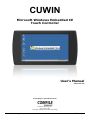
CUWIN
Microsoft Windows Embedded CE
Touch Controller
User's Manual
2011-12-13
“Everything for Embedded Control”
Comfile Technology Inc.
www.cubloc.com
Copyright 1996,2010 Comfile Technology
Comfile Technology Inc.
CUWIN – User's Manual
1 of 72
Table Of Contents
Preface ......................................................................................................................3
Overview ...................................................................................................................4
Powering On the CUWIN for the First Time ...........................................................6
Setting the CUWIN's Operating Mode..........................................................................................6
Powering On the CUWIN .............................................................................................................7
Connecting the CUWIN to a Personal Computer (PC) ..........................................9
Installing the USB Driver (Windows 7) .........................................................................................9
Installing the USB Driver (Windows XP).......................................................................................9
ActiveSync (Windows XP)..........................................................................................................13
Windows Mobile Device Center (Windows Vista, 7)...................................................................21
Developing Software for the CUWIN ....................................................................27
Installing Visual Studio 2008 ......................................................................................................27
Installing the CUWIN Software Development Kit (SDK) .............................................................32
Creating Our First CUWIN Program...........................................................................................37
Interfacing the CUWIN to Other Devices..............................................................45
RS-232 .......................................................................................................................................45
Writing to the CUWIN's Serial Port .........................................................................................45
Reading from the CUWIN's Serial Port...................................................................................54
Modbus ......................................................................................................................................58
Using Modbus to Interface the CUWIN to the CUBLOC.........................................................59
Setting Up the CUBLOC .........................................................................................................62
Programming the CUWIN .......................................................................................................64
Comfile Technology Inc.
CUWIN – User's Manual
2 of 72
Preface
This document was created to help our customers quickly explore and enjoy the CUWIN without having
to spend much effort reading documentation and experimenting beforehand. This document will help
users connect the CUWIN to a PC, transfer files to and from the CUWIN and a PC, program the CUWIN,
and interface the CUWIN to other digital devices like the CUBLOC.
The exercises in this document will make use of Visual Studio 2008, the C# programming language,
and the .Net Compact Framework, but the CUWIN can be programmed in any programming language
and development environment that is compatible with Windows Embedded CE 6.0 and the CUWIN's
processor. This includes, but is not limited to, Visual Basic and C++.
This document will make use of the CUWIN5200, but all examples can be easily adaptable to any
CUWIN model with little or no modification.
We hope this document will reveal just how easy it is to quickly begin using the CUWIN, develop
software, and interface the CUWIN to almost any digital device.
Comfile Technology Inc.
CUWIN – User's Manual
3 of 72
Overview
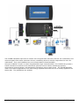
The CUWIN is a Windows Embedded CE touch controller primarily targeted for use as a Human
Machine Interface(HMI).
The CUWIN's front panel features an 800x480 color touch screen capable of receiving input from a
human user, by touching the screen, and displaying colorful information.
The CUWIN's rear and side panels feature several interfaces (RS232/485, USB, Ethernet, Audio, SD
Card) for communicating with many different electronic devices.
Comfile Technology Inc.
CUWIN – User's Manual
4 of 72
The CUWIN translates input from a human user to signals that electronic devices can understand, and
receives signals from those electronic devices, translating them to colorful output that the user can
understand. Thus, the CUWIN serves as a Human Machine Interface(HMI).
Using the CUBLOC, TinyPLC or other Programmable Logic Controllers(PLC), the CUWIN can provide a
human interface to electronic and mechanical systems such as robots, monitoring systems,
environment control systems, and automation equipment just to name a few. The CUWIN has been
used in all kinds of applications from solar energy systems that track the sun to beauty appliances for
styling hair. The possibilities are endless.
Comfile Technology Inc.
CUWIN – User's Manual
5 of 72
Powering On the CUWIN for the First Time
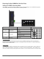
Setting the CUWIN's Operating Mode
The CUWIN is very flexible and can operate in many modes depending on the CUWIN's final purpose.
The following table lists the CUWIN's different operating modes.
Position
Position
1
2 and 3
4, 5, and 5
Function
Boot Device
Boot Mode
Reserved
Mode
1
SDCard
Off
NAND Flash
On
2
3
4
Reserved
On On
Auto-Run Mode
On Off
Development Mode
Off Off
OS Image Download Mode
Off On
5
6
Reserved
Development Mode
For the exercises in this document we need to set the CUWIN's operating mode to Development
Mode.To set the CUWIN's operating mode to Development Mode set position 1 to ON and positions 2
through 6 OFF as shown above.
AutoRun Mode
To configure the CUWIN to automatically start a program when the system boots, create a folder the
folder “\Flash Disk\AutoRun” and copy the *.exe file to execute into that folder. Then configure the
device for AutoRun mode by setting DIP switch positions 1 and 2 to ON and positions 3 through 6 Off.
Comfile Technology Inc.
CUWIN – User's Manual
6 of 72
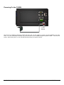
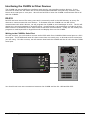
Powering On the CUWIN
Power
Switch
Now that the CUWIN's operating mode has been set, we are ready to power on the CUWIN for the first
time. It is not necessary to make any connections to the CUWIN except the power cable. Connect the
power cable and power on the CUWIN by depressing the power switch.
Comfile Technology Inc.
CUWIN – User's Manual
7 of 72
After a few seconds the Windows Embedded CE desktop will appear. To complete the exercises in this
document, it is not necessary to understand each of these features. For now, a simple overview will
suffice.
Item
Description
1
My Device
Opens the file explorer.
2
Recycle Bin
Storage for deleted files before permanent deletion.
3
Internet Explorer Internet browser
4
MacUtil
Utility to change the Network Interface Card(NIC)'s Media Access
Control(MAC) address.
5
Media Player
Windows CE Media player for playing audio and video files.
6
SaveRegs
Utility to permanently save any changes to the device's registry.
7
Start Button
Opens the Windows CE Start Menu
8
System Tray
Windows CE System Tray
9
Show Desktop
Minimizes any open windows and shows the Windows CE desktop.
10
Input Panel
Opens the Windows CE Input Panel (onscreen keyboard)
Comfile Technology Inc.
CUWIN – User's Manual
8 of 72
Connecting the CUWIN to a Personal Computer (PC)
In order to customize the CUWIN for your needs you will likely need to transfer data and programs to
the CUWIN. Typically this is done by connecting the CUWIN to a Personal Computer (PC).
In order for a PC to communicate with the CUWIN, a USB device driver must be installed on the PC.
Once the driver is installed, ActiveSync (Windows XP) or Windows Mobile Device Center (Windows
Vista and Windows 7) can be used to copy data and programs to and from a PC and the CUWIN.
Installing the USB Driver (Windows 7)
Windows 7 already includes a driver for the CUWIN. Simply connect the CUWIN and the PC via a USB
cable, and Windows will download a driver from Windows Update. It will appear as “Anchor USB EZLink Cable”. After the driver is installed, the CUWIN will appear in the list of portable devices.
Installing the USB Driver (Windows XP)
The following instructions describe how to install the CUWIN's USB driver on the PC.
1.
Download the “ActiveSync USB Driver [CUWIN5000 series]” file from the Comfile Technology
website at http://www.cubloc.com/data/07.php, and unzip the file to a folder of your choosing.
Comfile Technology Inc.
CUWIN – User's Manual
9 of 72
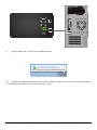
2.
Using a USB cable, connect the CUWIN to the PC.
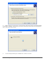
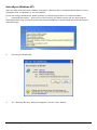
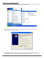
3.
After connecting the CUWIN to the PC, the “Found New Hardware Wizard” will appear. Select
“Install from a list or specific location(Advanced)” and click the “Next” button.
Comfile Technology Inc.
CUWIN – User's Manual
10 of 72
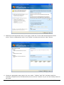
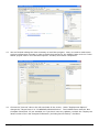
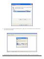
4.
Select “Search for the best driver in these locations” radio button and the “Include this location
in the search:” checkbox. Then, browse to the folder containing the drivers that were downloaded in
step 1, and click the “Next” button.
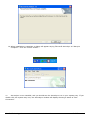
5.
The PC will begin searching for a suitable driver. Wait for it to finish.
Comfile Technology Inc.
CUWIN – User's Manual
11 of 72
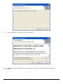
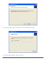
6.
When it locates the driver, it will display a dialog box as shown above. Click the “Continue
Anyway” button.
7.
The driver will then install. When it is finished, the window above will appear. Click the “Finish”
button.
Comfile Technology Inc.
CUWIN – User's Manual
12 of 72
ActiveSync (Windows XP)
After the USB driver has been installed, ActiveSync (Windows XP) or Windows Mobile Device Center
(Windows Vista, or Windows 7) can be installed.
If you are running Windows XP, please perform the following procedure to install ActiveSync.
1.
Download ActiveSync – At the time of this writing, the latest version was 4.5 and could be
downloaded from http://www.microsoft.com/windowsmobile/en-us/downloads/microsoft/activesyncdownload.mspx
2.
Run the downloaded file.
3.
If a “Security Warning” dialog box appears, click the “Run” button.
Comfile Technology Inc.
CUWIN – User's Manual
13 of 72
4.
On the following screen, click the “Next” button.
5.
Read the license agreement and, if you agree, accept the license agreement and click the
“Next” button.
Comfile Technology Inc.
CUWIN – User's Manual
14 of 72
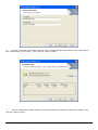
6.
On the “Customer Information” dialog, enter the appropriate information in the “User Name”
and “Organization” text boxes. Then click the “Next” button.
7.
On the “Destination Folder” dialog, accept the default or change the destination folder. Then
click the “Next” button.
Comfile Technology Inc.
CUWIN – User's Manual
15 of 72
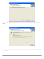
8.
A dialog will appear telling you that you are ready to install the program. Click the “Install”
button.
9.
A new dialog with a progress bar will then appear showing the status of the installation. Wait for
it to complete.
Comfile Technology Inc.
CUWIN – User's Manual
16 of 72
10. When installation is complete, a dialog will appear saying “Microsoft ActivSync 4.5 Setup is
complete”. Click the “Finish” button.
11.
ActiveSync is now installed, and you should see the ActiveSync icon in your system tray. If you
double-click the system tray icon, the ActiveSync window will display showing a status of “Not
Connected.”
Comfile Technology Inc.
CUWIN – User's Manual
17 of 72
12.
Using a USB cable, connect the CUWIN to the PC.
13.
You will probably hear a few sounds from the PC and the CUWIN and a small dialog will briefly
appear on the CUWIN.
Comfile Technology Inc.
CUWIN – User's Manual
18 of 72
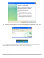
14.
ActiveSync will then prompt you to create a partnership between the PC and the CUWIN. Make
your selection. If you're not sure, just choose “No”. Then click the “Next” button.
15.
ActiveSync will now show a status of “Connected”, and the ActiveSync system tray icon will
change indicating the CUWIN is connected to the PC. Click the “Explore” icon.
Comfile Technology Inc.
CUWIN – User's Manual
19 of 72
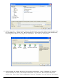
16.
Using Windows Explorer, you will now be able to view the CUWIN's file system and transfer files
to and from the CUWIN just as you would on the PC.
Comfile Technology Inc.
CUWIN – User's Manual
20 of 72
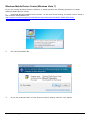
Windows Mobile Device Center (Windows Vista, 7)
If you are running Windows Vista or Windows 7, please perform the following procedure to install
Windows Mobile Device Center.
1.
Download Windows Mobile Device Center. At the time of this writing, the latest version was 6.1
and could be downloaded from
http://www.microsoft.com/downloads/details.aspx?FamilyId=46F72DF1-E46A-4A5F-A79109F07AAA1914&displaylang=en
2.
Run the downloaded file.
3.
If you are presented with a “User Account Control” dialog, click the “Yes” button.
Comfile Technology Inc.
CUWIN – User's Manual
21 of 72
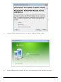
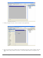
4.
Windows Mobile Device Center will begin installing. Wait for it to finish.
5.
When the installation is finished, a message will appear in the system tray telling you that the
installation was successful.
6.
Run “Windows Media Device Center” from the Windows Start Menu.
Comfile Technology Inc.
CUWIN – User's Manual
22 of 72
7.
Read the license agreement and, if you agree, click the “Accept” button.
8.
Windows Mobile Device Center will open, and will indicate a status of “Not Connected”.
Comfile Technology Inc.
CUWIN – User's Manual
23 of 72
9.
Using a USB cable, connect the CUWIN to the PC.
10.
Windows will begin installing a driver for the CUWIN. When it is finished, a message will display
in the system tray saying “Your device is ready to use.”
Comfile Technology Inc.
CUWIN – User's Manual
24 of 72
11.
Windows Mobile Device Center will begin connecting with the CUWIN. When it is finished, it will
display a status of connected. At this time you can use Windows Mobile Device Center to do many
things with the CUWIN. You are encouraged to read the Windows Mobile Device Center documentation
for more information. For this exercise, however, we just want to transfer files, so click “Connect
without setting up your device”.
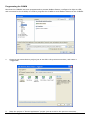
12.
Under “File Management” click “Browse the contents of your device.”
Comfile Technology Inc.
CUWIN – User's Manual
25 of 72
13.
Using Windows Explorer you will be able to view the CUWIN's file system and transfer files to
and from the CUWIN just as you would on the PC.
Comfile Technology Inc.
CUWIN – User's Manual
26 of 72
Developing Software for the CUWIN
In order to develop software for the CUWIN a software development environment must be installed.
This document will make use of Microsoft's Visual Studio 2008 as a development environment, but any
software development environment capable of producing Windows Embedded CE programs compatible
with the CUWIN's processor can be used.
Visual Studio supports several programming languages; primarily Visual C++, C#, and Visual
Basic.Net, and can produce two kinds of programs: managed and unmanaged(native) programs.
Managed programs rely on the .Net Framework while unmanaged programs do not. Visual C++ can
produce either managed or unmanaged programs, but C# and Visual Basic.Net are primarily used to
produce managed programs. For this document we will be programming in C# so our programs will be
managed and will thus rely on the .Net Framework.
The .Net Framework is an extremely large collection of libraries and application programming
interfaces (APIs) for Windows operating systems. It is much too large for embedded systems that are
intended to be small and light, like the CUWIN. Therefore, Microsoft has created the .Net Compact
Framework to suit the small and light needs of the embedded systems market. The CUWIN comes
with the .Net Compact Framework 3.5 pre-installed and the example programs produced in this
document will be built to make use of it.
Installing Visual Studio 2008
Visual Studio Express editions don't support smart device development. Visual Studio 2010 also
doesn't yet support smart device development. Only Visual Studio 2008 Professional or higher
supports smart device development for the .Net Compact Framework 3.5, so Visual Studio 2008
Professional will be our development environment of choice for this document.
This document will only show the installation process for Windows XP, but the installation process for
Windows Vista and Windows 7 is quite similar.
1. If you don't yet own Visual Studio 2008, you can download a 90-day trial version at
http://www.microsoft.com/downloads/details.aspx?FamilyID=83c3a1ec-ed72-4a79-896125635db0192b. The downloaded file must be burned to a DVD. Use a DVD burner to burn the
*.iso image to a DVD disc.
2. Insert your Visual Studio 2008 DVD into your DVD drive to begin the installation.
Comfile Technology Inc.
CUWIN – User's Manual
27 of 72
3. Click the “Install Visual Studio 2008” link to begin the installation.
4. A welcome screen will appear. Click “Next” to continue.
Comfile Technology Inc.
CUWIN – User's Manual
28 of 72
5. Read the license agreement and, if you agree, check the “I have read and accept the license
terms.” Enter an appropriate name in the “Name” text box and click the “Next” button.
6. Choose an appropriate setup option for your needs. “Default” and “Full” will both install the
necessary components for this document, but we will use “Custom” so you can see exactly what we
will need.
Comfile Technology Inc.
CUWIN – User's Manual
29 of 72
7. In order to program for the .Net Compact Framework, you must choose the “Smart Device
Programmability” option. And, since we will be programming in C#, be sure to check the Visual C#
option. Then click the “Install” button.
8. Visual Studio 2008 will begin installing. Wait for the installation to complete. It may take some
time.
Comfile Technology Inc.
CUWIN – User's Manual
30 of 72
9. When the installation is complete, the above screen will appear. No further action is necessary, but
if you wish, you can download and install MSDN documentation and other updates from this screen.
Make your choice or click the “Finish” button.
10. The above screen will then appear. From this screen you can modify your Visual Studio installation,
install MSDN documentation, and/or check for updates. At this time it is recommended that you
update your computer by clicking the “Check for Service Releases” link, or by using Windows
Update. Make your choice or click the “Exit” button.
Comfile Technology Inc.
CUWIN – User's Manual
31 of 72
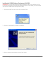
Installing the CUWIN Software Development Kit (SDK)
IMPORTANT: You must install Visual Studio before installing the SDK or the installation may fail.
In order for Visual Studio to build and debug applications specific to the CUWIN, you must download
and install the CUWIN Software Development Kit (SDK).
1. Download the SDK from http://www.cubloc.com/data/07.php
2. Execute the downloaded file to begin the installation.
3. When the welcome screen appears, click the “Next” button.
Comfile Technology Inc.
CUWIN – User's Manual
32 of 72
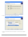
4. Read the license agreement and, if you agree, choose “Accept” and click the “Next” button.
5. On the “Customer Information” dialog, enter the appropriate information the in “User Name” and
“Organization” text boxes. Then click the “Next” button.
Comfile Technology Inc.
CUWIN – User's Manual
33 of 72
6. Choose “Custom”. If you choose “Complete” the installation may fail.
7. Remove the “Documentation” feature from the installation. If you don't do this, the installation
may fail.
Comfile Technology Inc.
CUWIN – User's Manual
34 of 72
8. We are now ready to begin the installation. Click the “Install” button to begin.
9. The SDK will begin installing. Wait for it to finish.
Comfile Technology Inc.
CUWIN – User's Manual
35 of 72
10.
When the installation is finished a dialog will display saying “Completing the CUWIN2450 Setup
Wizard”. Click the “Finish” button.
Comfile Technology Inc.
CUWIN – User's Manual
36 of 72
Creating Our First CUWIN Program
Now that the development environment is installed, we are ready to develop programs for the CUWIN.
In this section, we will create a very simple “Hello World” program. Although this program is very
simple, it will illustrate the process that we must go through to develop, deploy and debug any CUWIN
program.
1. Start Visual Studio 2008 by selecting it from the Start Menu.
2. If this is your first time to run Visual Studio, it will ask you to choose your primary development
environment. For the exercises in this document, it is recommended that you choose “Visual C#
Development Settings”. Then click the “Start Visual Studio” button.
Comfile Technology Inc.
CUWIN – User's Manual
37 of 72
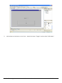
3. Visual Studio will open to the “Start Page”. Now we need to create a project.
4. Select “File”->”New...”->”Project...” from the menu.
Comfile Technology Inc.
CUWIN – User's Manual
38 of 72
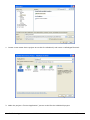
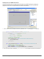
5. Select “Visual C#”->“Smart Device” from the “Project Types” tree, and “Smart Device Project” from
the “Templates” list. Makes sure “.Net Framework 3.5” is selected from the top, right-hand corner,
and change the “Name” of the project to “HelloWorld”. Then click the “OK” button.
6. Another dialog will display asking for more project configuration. Select “Windows CE” from the
“Target Platform” list, and “.Net Compact Framework 3.5” from the “.Net Compact Framework
Version” list. Then, select “Device Application” from the “Templates” list, and click the “OK” button.
Comfile Technology Inc.
CUWIN – User's Manual
39 of 72
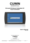
7. Finally, the project will open, and we are ready to start programming.
8. Move your mouse over the “Toolbox” tab on the left side of the screen, and the “Toolbox” menu will
open. Select or drag a “Button” to the form. A new button labeled “button1” will appear on the
form.
Comfile Technology Inc.
CUWIN – User's Manual
40 of 72
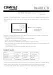
9. Position the button to the bottom of the form, and resize the button so it is easy to touch on the
touch screen.
10.
If the “Properties” window is not yet displayed, select “View”->”Properties Window” from the
menu, and it should appear in the bottom, right-hand corner of the screen.
Comfile Technology Inc.
CUWIN – User's Manual
41 of 72
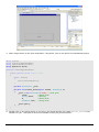
11.
In the “Properties” Window change the “Text” property to “Say Hello” and press the “Enter” key.
You'll see the button's label change to “Say Hello”
12.
Now, double-click on the button and you will be taken to the button's event handler. It is here
you you tell the program what to do when the button is clicked. Add the line
MessageBox.Show(“Say Hello!”);
Comfile Technology Inc.
CUWIN – User's Manual
42 of 72
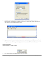
13.
We are finished editing the code necessary to build this program. Now, we need to make some
project configuration changes in order to build the program for the CUWIN. Right-click the “Hello
World” project node in the “Solution Explorer” window, and choose “Properties”.
14.
Choose the “Devices” tab on the left-hand side of the screen. Under “Deployment Options”
change the “Target Device” to “CUWIN2450 ARMV4I Device”. The CUWIN comes with the .Net
Compact Framework 3.5 pre-installed, so if you don't have any updates, uncheck the “Deploy the
latest version of the .Net Compact Framework (including Service Packs)” checkbox.
Comfile Technology Inc.
CUWIN – User's Manual
43 of 72
15.
To execute the program, ensure the CUWIN in powered on and is connected to the PC, and click
the “Start Debugging” button on the toolbar.
16.
If a “Deploy HelloWorld” dialog is displayed, choose “CUWIN2450 ARMV4I Device” from the
“Device” options, and click the “Deploy” button. The program will compile, upload to the CUWIN,
and begin executing.
17.
The program's main window will then appear on the CUWIN. Touch the “Say Hello” button and a
message box will appear saying “Hello!”.
Comfile Technology Inc.
CUWIN – User's Manual
44 of 72
Interfacing the CUWIN to Other Devices
The CUWIN has several different interfaces with which it can interface to other devices. In the
exercises to follow we will make use of the Recommended Standard 232 (RS-232) interface, also
known as a serial port or com port. We will use RS-232 to have the CUWIN communicate with a PC
and the CUBLOC.
RS-232
RS-232 has been around for many years and is commonly used in the HMI industry as a way for
devices to communicate with one another. To illustrate how the CUWIN can use RS-232 to
communicate with other devices, we will program the CUWIN to send messages to a PC. The PC will
display the received messages in HyperTerminal. HyperTerminal is an application included in all the
latest versions of Windows, and is well-suited for RS-232 communication. Finally we will modify this
program to read keystrokes in HyperTerminal and display them on the CUWIN.
Writing to the CUWIN's Serial Port
For this exercise, you will need to connect an RS-232 cable from CUWIN's COM1 serial port to a PC's
serial port. The CUWIN and most PCs have more than one serial port, so be aware which serial port
you are using. For this exercise, we will assume that both the CUWIN and the PC will use their COM1
serial port.
You should now have two connections between the CUWIN and the PC: USB and RS-232.
Comfile Technology Inc.
CUWIN – User's Manual
45 of 72
1. Create a new smart device project as we did for HelloWorld, and name it HelloHyperTerminal.
2. Make the project a “Device Application” just as we did for the HelloWorld project.
Comfile Technology Inc.
CUWIN – User's Manual
46 of 72
3. Add a large button to the form and label it “Say Hello” just as we did for the HelloWorld project.
using
using
using
using
System;
System.ComponentModel;
System.Windows.Forms;
System.IO.Ports;
namespace HelloHyperTerminal
{
public partial class Form1 : Form
{
public Form1()
{
InitializeComponent();
}
private SerialPort _port;
private void Form1_Load(object sender, EventArgs e)
{
_port = new SerialPort("Com1", //Com port
19200,
//Baud Rate
Parity.None,
//Parity
8,
//Data Bits
StopBits.One); //Stop Bits
_port.Open();
}
}
}
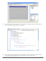
4. Double-click in any blank space on the form, and Visual Studio will create a Form1_OnLoad event
handler for you. Add code to this event handler exactly as pictured above.
Comfile Technology Inc.
CUWIN – User's Manual
47 of 72
5. Go back to the “Form1.cs [Design]” tab. Select the form, and in the “Properties” window click the
lightning bolt icon
. This will display all of the events that you can attach event handlers to.
Double-click the “Closing” event and a Form1_Closing event handler will be created.
private void Form1_Closing(object sender, CancelEventArgs e)
{
//Close the serial port
_port.Close();
}
6. Add code to this event handler exactly as pictured above.
private void button1_Click(object sender, EventArgs e)
{
//Send "Hello!" to HyperTerminal
_port.Write("Hello!\r\n");
}
7. Go back to the “Form1.cs [Design]” tab, and double-click the “Say Hello” button. This will add a
button1_Click event handler. Add code to this event handler exactly as pictured above.
Comfile Technology Inc.
CUWIN – User's Manual
48 of 72
8. Finally adjust the project properties just as we did in the HelloWorld project.
How the Code Works:
1. When the form opens, the form's Load event fires executing the Form1_Load event handler. This
event handler configures the COM1 serial port and opens it so we can write to it.
2. When we close the form, the form's Closing event fires calling the Form1_Closing event handler.
This event handler closes the COM1 serial port.
3. When we touch the “Say Hello” button, the button's Click event fires calling the button1_Click
event handler. This event handler writes “Hello!” to the serial port. The “\r” and “\n” characters
are a carriage return and line feed, so each “Hello!” we send appears on a new line.
Comfile Technology Inc.
CUWIN – User's Manual
49 of 72
Displaying our “Hello!” Message on the PC
We now need some device to read and display the “Hello!” being sent from the CUWIN. For this we
will use the program, HyperTerminal, which is included in Windows XP.
1. Start HyperTerminal by selecting Start-->All Programs-->Accessories-->Communications->HyperTerminal in the Windows start menu.
2. You may be prompted to configure your Location information. You only need to select your
country/region and enter you area code. These settings are not necessary for this exercise, but
HyperTerminal requires it. After you are finished, click the “OK” button.
Comfile Technology Inc.
CUWIN – User's Manual
50 of 72
3. You may then be prompted to edit dialing rules. Again, this is not necessary for this experiment.
Just click the “OK” button.
4. HyperTerminal will open and display a “Connection Description” dialog. It is here we need to
Comfile Technology Inc.
CUWIN – User's Manual
51 of 72
configure the PC's serial port. Enter “CUWIN” in the “Name” textbox and click the “OK” button.
5. In the “Connect Using” drop-down list, select the serial port you wish to use. Note that this is the
PC's serial port, not the CUWIN's serial port; they may be different. Then, click the “OK” button.
6. A new dialog will appear asking for your port settings. These settings must match those settings
made in the Form1_Load event handler of the CUWIN program or the PC and the CUWIN will not
be able to communicate with one another. Adjust the settings appropriately, then click the “OK”
button.
Comfile Technology Inc.
CUWIN – User's Manual
52 of 72
7. Execute the CUWIN program from Visual Studio.
8. The form will display on the CUWIN. Click the “Say Hello” button.
9. Take a look at the PC's HyperTerminal window. You will see the “Hello!” message sent from the
CUWIN.
Comfile Technology Inc.
CUWIN – User's Manual
53 of 72
Reading from the CUWIN's Serial Port
We have successfully built an program that writes data to the CUWIN's serial port, sending it to
HyperTerminal on the PC, but communication is usually bi-directional. We will now modify this
program to read input from HyperTerminal, and send it to the CUWIN.
1. Add a “Label” from the Toolbox to the form, and label it “PC: ” by changing its Text property.
private void Form1_Load(object sender, EventArgs e)
{
_port = new SerialPort("Com1", //Com port
19200,
//Baud Rate
Parity.None,
//Parity
8,
//Data Bits
StopBits.One); //Stop Bits
//Listen for incoming data
_port.DataReceived += new SerialDataReceivedEventHandler(
_port_DataReceived);
_port.Open();
}
void _port_DataReceived(object sender, SerialDataReceivedEventArgs e)
{
//Update label1 with the data read
string dataRead = _port.ReadExisting();
label1.Invoke(new Action(() => label1.Text += dataRead));
}
2. Go to the Form.cs tab, and add the _port_DataReceived event handler exactly as pictured above.
Comfile Technology Inc.
CUWIN – User's Manual
54 of 72
How the Code Works:
1. When data is received on the CUWIN's serial port, the DataReceived event is fired, which executes
the _port_DataRecieved event handler.
2. In the _port_DataRecieved event handler, we read the data from the CUWIN's serial port, and
append the data to the “PC:” label. NOTE: The Invoke method is necessary because the
_port_DataRecieved event handler will be running on a different thread than the one used to
create the label. Also, the code inside the Invoke method is a lambda expression which is new to
C# 3.0. See the Microsoft Development Network (MSDN) documentation for Control.Invoke and
Lambda Expressions for more information.
Configuring HyperTerminal to Accept Keystrokes
Now we must configure HyperTerminal to accept keystrokes, show them on the screen, and send them
to the CUWIN.
1.
In HyperTerminal with the CUWIN connection open, select File->Properties from the menu. The
“CUWIN Properties” dialog will appear. On the “Settngs” tab, click the “ASCII Settup...” button.
Comfile Technology Inc.
CUWIN – User's Manual
55 of 72
2.
Check the “Echo typed characters locally” checkbox. This will ensure that as we type in
HyperTerminal, our keystrokes will appear on the screen. Click the “OK” button, then click the
“OK” button on the “CUWIN Properties” dialog.
3.
Hyperterminal will not accept keyboard input until the Scroll Lock is turned off. Press the “Scroll
Lock” key on your keyboard until the status bar shows “Scroll” in gray (disabled). Now if we type
in HyperTerminal, what we type will display on the screen and will be sent to the CUWIN.
Running the Program
We are now ready to run the program.
1.
Once again, execute the CUWIN program from Visual Studio.
Comfile Technology Inc.
CUWIN – User's Manual
56 of 72
2.
When the form appears on the CUWIN, touch the “Say Hello” button and “Hello!” will appear in
HyperTerminal. Then type “Hi!” in HyperTerminal and the CUWIN will display “Hi!” in the “PC:”
label.
Comfile Technology Inc.
CUWIN – User's Manual
57 of 72
Modbus
We've now seen how we can program the CUWIN to send and receive data over the its serial port
using RS-232. However, in that program we transmitted only human readable character data. Most
digital devices probably don't know what “Hello!” and “Hi!” mean. If we want to communicate with
electronic devices we must speak their language.
Enter Modbus. Modbus is a protocol created by Modicon in 1979 to communicate with industrial
electronic devices, and has proliferated to become the de facto standard in the industry.
Modbus uses a request/reply protocol with a single master device and one or more slave devices. The
master sends a request to a single slave, and that slave replies with a response to the master's
request. A slave can only respond to requests from the master; it cannot initiate communication on
its own. These requests and replies are called frames.
Modbus supports two frame formats: Remote Terminal Unit (RTU) and American Standard Code for
Information Interchange (ASCII). The RTU format encodes each frame in a compact, binary form and
uses a Cyclic Redundancy Check (CRC) to verify the integrity of the transmission. The ASCII format
encodes each fram as a set of ASCII characters and uses a Longitudinal Redundancy Check (LRC) to
verify the integrity of the transmission.
Modubus request frames vary, but typically they contain the following:
1.
Slave Address – The address of the slave device the request is intended for
2.
Function Code – The function to performed on the slave device (read, write, etc...)
3.
Data – Information needed to perform the given function
4.
Error Code – CRC for RTU, or LRC for ASCII to verify the transmission integrity
Modbus reply frames also vary, but typically they contain the following:
1.
Slave Address – The address of slave device the reply is from
2.
Function Code – The function performed by the slave device
3.
Data – Information about the function performed
4.
Error Code – CRC for RTU, or LRC for ASCII to verify the transmission integrity
This very brief introduction to Modbus is all that is needed to understand the exercises to follow. It is
out of the scope of this document to explain Modbus in detail so, to learn more, please see The
Modbus Organization.
Comfile Technology Inc.
CUWIN – User's Manual
58 of 72
Using Modbus to Interface the CUWIN to the CUBLOC
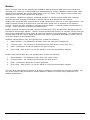
In this exercise, we will interface the CUWIN to a CUBLOC to toggle an LED on and off.
First the CUWIN must ask the CUBLOC if the LED is on or off.
What’s Your
Status?
OK, I’m
Off!
OFF
Turn On
OK, I’m
On!
ON
Then, the CUWIN will tell the CUBLOC to turn the LED on (if the LED was off), or off (if the LED was
on).
Comfile Technology Inc.
CUWIN – User's Manual
59 of 72
The following Modbus frames are listed here to help you understand the exercise to follow. To keep
this exercise simple for the purpose of learning, we will hard-code these frames in our program.
Reading the State of the LED
To ask the CUBLOC what the state of the LED is, we issue the following Modbus frame.
Request
Value
Description
0x01
Slave Address 1
0x02
Read Bit
0x0000
Register Address 0 (Port 0)
0x0001
Read only 1 bit
0xB9CA
CRC
If the LED is off, the CUBLOC will respond with the following Modbus frame:
Reply
Value
Description
0x01
Slave Address 1
0x02
Read Bit
0x01
1 Bit Read
0x00
LED is off
0xA188
CRC
If the LED is on, the CUBLOC will respond with the following Modbus frame:
Reply
Value
Description
0x01
Slave Address 1
0x02
Read Bit
0x00
1 Bit Read
0x01
LED is on
0x6048
CRC
Comfile Technology Inc.
CUWIN – User's Manual
60 of 72
Turning the LED On:
To have the CUBLOC turn the LED on, we issue the following Modbus frame.
Request
Value
Description
0x01
Slave Address 1
0x05
Write bit
0x0000
Register Address 0 (Port 0)
0xFF00
Turn the LED on
0x8C3A
CRC
The CUBLOC will respond with the following Modbus frame (an echo of the request):
Reply
Value
Description
0x01
Slave Address 1
0x05
Read Bit
0x0000
Register Address 0 (Port 0)
0xFF00
The LED was turned on
0x8C3A
CRC
Turning the LED Off
To have the CUBLOC turn the LED off, we issue the following Modbus frame.
Request
Value
Description
0x01
Slave Address 1
0x05
Write bit
0x0000
Register Address 0 (Port 0)
0x0000
Turn the LED off
0xCDCA
CRC
The CUBLOC will respond with the following Modbus frame (an echo of the request):
Reply
Value
Description
0x01
Slave Address 1
0x05
Read Bit
0x0000
Register Address 0 (Port 0)
0x0000
The LED was turned off
0xCDCA
CRC
Comfile Technology Inc.
CUWIN – User's Manual
61 of 72
Setting Up the CUBLOC
Now that we have a general idea what Modbus is, we need to set up the CUBLOC to perform the task
at hand. Follow the following procedures to program the CUBLOC, connect one of its I/O ports to an
LED, and connect it to the CUWIN.
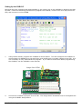
1.
Using Cubloc Studio, program the CUBLOC as shown above. This will configure the CUBLOC to
communicate via Modbus over its serial port, and enable port 0 to apply voltage to an LED. It is
not necessary to fully understand this program. If you want to learn more about programming
the CUBLOC, see the CUBLOC's user manual.
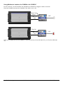
Jumper P0 to LED0
2.
Connect the CUBLOC's I/O port 0 to an LED. The image above illustrates how to accomplish this
using the CUBLOC Study Board.
Comfile Technology Inc.
CUWIN – User's Manual
62 of 72
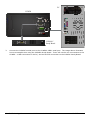
PC
CUWIN
CUBLOC
Study Board
3.
Connect the CUBLOC's serial port to the CUWIN's COM1 serial port. The image above illustrates
how to accomplish this using the CUBLOC Study Board. There will now be two connections to the
CUWIN: a USB connection to the PC, and an RS-232 connection to the CUBLOC Study Board.
Comfile Technology Inc.
CUWIN – User's Manual
63 of 72
Programming the CUWIN
Now that the CUBLOC has been programmed to process Modbus frames, configured to light an LED,
and connected to the CUWIN, we need to program the CUWIN to send Modbus frames to the CUBLOC.
1.
Create a new smart device project just as we did in the previous exercises, and name it
“ToggleLED”.
2.
Make the project a “Device Application” project just as we did in the previous exercises.
Comfile Technology Inc.
CUWIN – User's Manual
64 of 72
3.
Add a label and a button to the form. Label the button “Toggle” and the label “LED State”.
Comfile Technology Inc.
CUWIN – User's Manual
65 of 72
using
using
using
using
System;
System.ComponentModel;
System.Windows.Forms;
System.IO.Ports;
namespace ToggleLED
{
public partial class Form1 : Form
{
public Form1()
{
InitializeComponent();
}
private SerialPort _port;
private void Form1_Load(object sender, EventArgs e)
{
//Configure the serial port
_port = new SerialPort();
_port.PortName = "COM1";
_port.BaudRate = 19200;
_port.DataBits = 8;
_port.Parity = Parity.None;
_port.StopBits = StopBits.One;
//Open the serial port
_port.Open();
}
private void Form1_Closing(object sender, CancelEventArgs e)
{
//Close the serial port
_port.Close();
}
}
}
4.
Add the code above to the form's Load and Closing event handlers. This will configure the
CUWIN's serial port and open it when the form loads. When the form closes, the the serial port
will be closed.
Comfile Technology Inc.
CUWIN – User's Manual
66 of 72
using
using
using
using
using
System;
System.ComponentModel;
System.Windows.Forms;
System.IO.Ports;
System.Threading;
namespace ToggleLED
{
public partial class Form1 : Form
{
public Form1()
{
InitializeComponent();
}
private SerialPort _port;
private byte[] _response = new byte[8];
private ManualResetEvent _evt = new ManualResetEvent(false);
private void Form1_Load(object sender, EventArgs e)
{
//Configure the serial port
_port = new SerialPort();
_port.BaudRate = 19200;
_port.DataBits = 8;
_port.Parity = Parity.None;
_port.StopBits = StopBits.One;
//Listen for data arriving on the serial port
_port.DataReceived += new
SerialDataReceivedEventHandler(_port_DataReceived);
//Open the serial port
_port.Open();
}
private void Form1_Closing(object sender, CancelEventArgs e)
{
//Close the serial port
_port.Close();
}
void _port_DataReceived(object sender, SerialDataReceivedEventArgs e)
{
//Read data into _response buffer
_port.Read(_response, 0, _port.BytesToRead);
//Notify that a response was received
_evt.Set();
}
}
}
5.
Attach an event handler to the serial ports DataReceived event. This event handler will store the
frame received from the CUBLOC in the _response buffer, and notify the the form's thread (See
ManualResetEvent for more information) that the frame was received.
Comfile Technology Inc.
CUWIN – User's Manual
67 of 72
//Returns true if LED is on, false if LED is off
private bool ReadLEDState()
{
//slave address = 0x01
//function code = 0x02 - read bit
//register address = 0x00, 0x00
//read only 1 bit = 0x00, 0x01
//crc = 0xB9, 0xCA
byte[] request = { 0x01, 0x02, 0x00, 0x00, 0x00, 0x01, 0xB9, 0xCA };
//send request
_port.Write(request, 0, request.Length);
//Wait for a response
_evt.WaitOne();
_evt.Reset();
//byte[3] contains the LED's status
if (_response[3] == 0)
return false;
else
return true;
6.
}
Add a function called ReadLEDState that sends a Modbus frame to the CUBLOC to read the state
of the LED. This function will wait for a response frame from the CUBLOC (_evt.WaitOne()), and
examine the response. If the response frame's data is 0, then the LED is off and this method will
return false. Otherwise, the LED is on and this method will return true.
Comfile Technology Inc.
CUWIN – User's Manual
68 of 72
//If turnOn is true, turn on LED. Otherwise turn off LED
private void ChangeLEDState(bool turnOn)
{
//slave address = 0x01
//function code = 0x05 - write bit
//register address = 0x00, 0x00
//On or Off = OxFF 0x00 (on), 0x00 0x00 (0ff)
//crc = 0x8C 0x3A (on), 0xCD 0xCA (off)
byte[] request;
if (turnOn)
{
request = new byte[]
{ 0x01, 0x05, 0x00, 0x00, 0xFF, 0x00, 0x8C, 0x3A };
}
else
{
request = new byte[]
{ 0x01, 0x05, 0x00, 0x00, 0x00, 0x00, 0xCD, 0xCA };
}
//send request
_port.Write(request, 0, request.Length);
//Wait for a response
_evt.WaitOne();
_evt.Reset();
7.
}
Add a function called ChangeLEDState that sends a Modbus frame to the CUBLOC to turn the LED
on or off, and waits for a response frame from the CUBLOC (_evt.WaitOne()). The response
frame from the CUBLOC is not needed, so it is ignored.
Comfile Technology Inc.
CUWIN – User's Manual
69 of 72
private void button1_Click(object sender, EventArgs e)
{
//Is LED on or off?
bool isOn = ReadLEDState();
//Toggle LED
ChangeLEDState(!isOn);
//Confirm: Is LED on or off?
isOn = ReadLEDState();
//Update label
if (isOn)
label1.Text = "On";
else
label1.Text = "Off";
8.
}
We now have functions for reading and changing the state of the LED. We now need to add
attach an event handler to the button's Click event to toggle the state of the LED. After the
state is changed, the program will read the state of the LED and update the “LED State” label.
private void Form1_Load(object sender, EventArgs e)
{
//Configure the serial port
_port = new SerialPort();
_port.BaudRate = 19200;
_port.DataBits = 8;
_port.Parity = Parity.None;
_port.StopBits = StopBits.One;
//Listen for data arriving on the serial port
_port.DataReceived += new
SerialDataReceivedEventHandler(_port_DataReceived);
//Open the serial port
_port.Open();
//Is LED on or off?
bool isOn = ReadLEDState();
//Update label
if (isOn)
label1.Text = "On";
else
label1.Text = "Off";
9.
}
When the form loads, we should update the “LED State” label with the LED's initial state. To do
this, modify the Form1_Load event handler as shown above.
Comfile Technology Inc.
CUWIN – User's Manual
70 of 72
10.
Finally, adjust the project properties as we did in the previous exercises.
How the Code Works:
1.
When the form loads, the form's Load event fires, calling the Form1_Load event handler. This
event handler configures the CUWIN's serial port, attaches the _port_DataReceived event
handler, opens the port, and initializes the “LED State” label with the current state of the LED:
“On” or “Off”.
2.
When the “Toggle” button is clicked, the button's Click event fires, calling the button1_Click
event handler. This event handler reads the state of the LED, reverses the LED's state, confirms
the new state of the LED, and updates the “LED State” label with the LED's new state.
3.
The ReadLEDStatus function sends a Modbus frame to the CUBLOC asking for the value in
register 0x0000 (the value of port 0), then waits for a response from the CUBLOC.
4.
The ChangeLEDStatus function sends a Modbus frame to either set the value in register 0x0000
to 1 (turn on the LED), or set the value in register 0x0000 to 0 (turn off the LED) depending on
the value of the turnOn parameter. NOTE: The Modbus protocol requires us to send a value of
0x00FF to change register 0x0000's value to 1.
5.
The _port_DataReceived event handler receives a Modbus response frame from the CUBLOC,
stores the frame in the _response buffer, then notifies the form that the response has been
received.
6.
Finally when the form closes, the form's Close event fires, calling the Form1_Closing event
handler. This event handler closes the CUWIN's serial port.
Comfile Technology Inc.
CUWIN – User's Manual
71 of 72
Running the Program
We are now ready to run the program.
1.
Execute the CUWIN program from Visual Studio.
2.
When the form loads, you will see the “LED State” label update to the current state of the LED.
When you click the “Toggle” button, the LED's state will change and the “LED State” label will
update accordingly.
Final Thoughts
In an effort to keep this exercise simple for the purpose of learning, we have made several concessions.
To name a few, we are not generating the request frame's CRC dynamically, we are not checking the
response frame's CRC for transmission integrity, and we are waiting indefinitely for a response after
issuing a request. Please keep this in mind as you explore the design of your own programs.
Comfile Technology Inc.
CUWIN – User's Manual
72 of 72