1
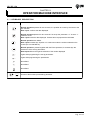
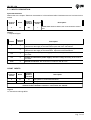
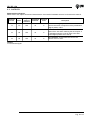
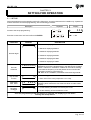
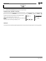
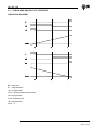
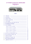
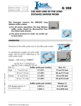
HB 235.12A
User's Manual
b
2 3 5 H1 2
CONTROLLER OF THE POSITION WITH SLOWING
HB 235.12A
INDEX OF SUBJECTS IN THIS MANUAL
CHAP. 1 - INTRODUCTION
-
Complementarity
References
Responsibility and validity
Description of operation
1-1
1-2
1-3
1-4
CHAP. 2 - OPERATOR / MACHINE INTERFACE
- Keyboard Description
- Inputs Description
- Outputs Description
2-1
2-2
2-3
CHAP. 3 - STARTUP
- Programming (set-up)
3-1
CHAP. 4 - USE
- Work programmes and auxiliary functions
- Tables and Graphics of Operation
4-1
4-2
CHAP. 5 - ASSISTANCE
- Instructions on How to Fill Up the Technical Assistance Fax
- Guarantee
5-1
5-2
Pag. 2 of 12
HB 235.12A
CHAPTER 1
INTRODUCTION
1 - 1 COMPLEMENTARITY
This manual is to be considered as a complement to the "Manual of installation, maintenance and assistance" which
supplies the indications for the performance of wirings, troubleshooting, procedures for startup and maintenance. This
manual contains indications for the instrument's use and for a correct programming.
We recommend therefore a careful reading and, in case of misunderstandings, please contact QEM for any further
explanation, by sending the Assistance Fax which you find enclosed to the manual.
1 - 2 REFERENCES
The documentation concerning the instruments which are designed and sold by QEM has been divided into various
sheets in order to allow an effective and quick reading according to the information being seeked.
User's Manual
Hardware Structure
Manual of installation,
maintenance and assistance
Explanation of the software
described
Basic information concerning the
hardware of the series and possibility
of customizations.
All what you need for Installation,
Maintenance and Assistance.
It is the present manual, which shows
all instructions for the comprehension
and the use of the instrument
described. It is a manual concerning
the instrument's software; it shows all
instructions for the comprehension,
programming, calibrations and use of
the instrument described.
Once you install the instrument by
following the instructions shown on
the Manual of Installation,
maintenance and assistance, with
this User's Manual you are supplied
with all necessary instructions for the
correct use of the instrument and for
its programming.
It is a sheet enclosed to this User's
manual, describing the hardware
configuration concerning the series of
the instrument described.
It also shows the electrical, technical
and mechanical characteristics, of
the series and also the possible hardware customizations according to the
software version.
Further explanation of all necessary
subjects for a correct installation and
maintenance.
This is made to allow us to supply
valid and safe instructions which shall
allow you to perform products with a
recognized quality and safe reliability.
It is also a valid support for all those
who must face a technical assistance
on an application which includes a
QEM's instrument.
Pag. 3 of 12
HB 235.12A
1 - 3 RESPONSIBILITY AND VALIDITY
RESPONSIBILITY
QEM is free from any responsibility for damages to people or things due to unobservance of the instructions and
prescriptions contained in this manual and in the "Manual of installation, maintenance and assistance". We also state
that the customer/purchaser must use the instrument according to the instructions supplied by QEM and in case of doubt
he must send a written application to QEM. Any authorization for further use and replacement shall be deemed as valid
by QEM, in case of contestation, only if it has been written by QEM.
No reprinting or republishing or delivery to third parties of this manual or of its parts is authorized unless a written
authorization is provided by QEM. Any infraction shall provoke a request of indemnization for damages on behalf of QEM.
All rights generated by patents or models are reserved.
QEM reserves the right to partially or integrally modify the characteristics of the instrument described and the enclosed
documentation
Purpose
The purpose of this manual is to indicate the general rules to use the instrument described.
Indication
Write down and carefully store all parameters concerning the settings and programming of the instrument in order to
make easier the eventual operations of replacement and assistance.
VALIDITY
This manual can be applied to all designed instruments, built and tested by QEM and having the same ordering code.
This document is integrally valid except for mistakes or omissions.
Instrument's
Release
Manual
Release
1
0
Modifications made to the Manual
New manual
Modifications
Date
22 / 04 / 04
Emesso dal Responsabile Documentazione:
........................................................
Approvato dal Responsabile di Prodotto:
........................................................
Pag. 4 of 12
HB 235.12A
1 - 4 DESCRIPTION OF OPERATION
The instrument HB 235.12A apart from displaying the position in the axis, this instrument also supplies output that render
it useful and a controller of the position visualized respect to the previously introduced.
Other two autput signal or indicate the position of zero machine and of slowing refer bye the zero.
If the count exceed the maximum visualization permitted, all of the figures beging to flash intermittently.
Pag. 5 of 12
HB 235.12A
CHAPTER 2
OPERATOR/MACHINE INTERFACE
2 - 1 KEYBOARD DESCRIPTION
Key
Function
Normal operation:pressed for two seconds, it is possible to access by the insert to the
pre-selection
Data input: confirms the data displayed.
Normal operation:pressed for two seconds if in set-up the parameter “C” is set to “1”
resets the count.
Data input:resets the data displayed. Pressed twice reproposed the initial data
Normal operation:not utilized.
Data input:increases bye impulse or in continuous mode the number selected on the
screen (the one that flashes)
Normal operation: pressed together with the Enter+password, it accesses bye the
introducion of the set-up parameters.
Data imput:shifts to the right the selection of the number displayed
Lights while programming the set-up parameters.
Lights while programming the preselection.
Not utilized.
Not utilized.
Not utilized.
+
Access to the functions protected by password.
Pag. 6 of 12
HB 235.12A
2 - 2 INPUTS DESCRIPTION
Inputs characteristics
Please refer to the chapter "Electrical characteristics" of the software leaflet "Hardware structure" enclosed to this
manual
Terminal
bloach
Name
4
I2
Logical
status of Activation
mode
activation
ON
I
Description
Count reset. When activated, the count showed is reset to
zero.
Legend
I = Impulsive Signal.
Name
Terminal
bloach
+
1
Positive of transducers' power supply. Positive of voltage supplied by the
instrument for the supply of the instruments' inputs and of the transducers
-
2
Negative of transducers' power supply. Negative of voltage supplied by the
instrument for the supply of the instruments' inputs and of the transducers.
Vac
7
Voltage of instrument's power supply. Alternated voltage according to the code of
your order.
Vac
8
Voltage of instrument's power supply. Alternated voltage according to the code of
your order.
GND
9
Ground Connection. We recommend a conductor with Ø 4 mm.
Description
COUNT INPUTS
Terminal
bloach
Name
Logical
statusof
activation
5
F1
N
Input "phase 1" incremental transducer.
6
F1
N
Input "phase 2" incremental transducer.
Description
For the characteristics of count inputs please refer to the chapter "Electrical characteristics" of the
software leaflet "Hardware structure" enclosed to this manual
Legend
N = Transducer with logic NPN
Pag. 7 of 12
HB 235.12A
2 - 3 OUTPUTS
Characteristics of outputs
Please refer to the chapter "Electrical Characteristics" of the leaflet "Hardware structure" enclosed to this manual.
Terminal
bloach
Name
Logical
status of
activation
Polarization
terminal
Activation
mode
Description
11
U1
ON
10
C
Preselectin targhet position. Access when the
count is the same or major than to the preselection
targhet position value.
12
U2
ON
10
C
Slow-down. This output is uset to reduce the
speed of the axis when reaching the arrival point. It
is activation when the count is minor to the slow
down targhet position set to set-up.
13
U3
ON
10
C
Zero position. Access when the count is the
same or minor to zero.
Legend
C = Continuous signal.
Pag. 8 of 12
HB 235.12A
CHAPTER 3
SETTING FOR OPERATION
3 - 1 SET-UP
As these parameters set the operating mode of the instrument, access is restricted to the installer only. A password
must be entered to access the programming, with the following procedure:
Description
Keyboard
Access to the set-up programming.
+
Display
= ON
Enter the access code "235" and confirm with ENTER.
FUNCTION
DISPLAY
DESCRIPTION
0
P
000
H
0 = Maximun displayng 999999.
1 = Maximun displayng 99999.9.
2 = Maximun displayng 9999.99.
Decimal digits
3 = Maximun displayng 999.999.
4 = Maximun displayng 99.9999.
5 = Maximun displayng 9.99999.
L
400000
C
0
Encoder
resolution
Key CLEAR
function
This parameter sets what the encoder revolution impulses must be
multiplied by to have the length display in the desired unit of targhet
position. Values from 0.00200 to 4.00000 can be entered, bearing
in mind that the frequency of the PH phases must not exceed the
instrument’s maximum count frequency.
N.B. Refer to the “Installation, maintenance and servicing manual”.
0 = Functioning prevented
1 = Zero reset of the count (outputs U2 e U3 = ON).
Slow down
Max. 9999
FL
Recupero
conteggio
A
9999
0
By this parameter is possible to establish the distance of the
positioning level at which the axis must slow down to make easier
the stop.
0 = At the switching off it does not recovery the count.
1 = At the switching off it recoveries the count.
Once the programming of the last function is achieved, the displaying in use before
entering the set-up returns.
Pag. 9 of 12
HB 235.12A
CHAPTER 4
USE
4 - 1 WORK PROGRAMMES AND AUXILIARY FUNCTIONS
INTRODUCTION TARGHET POSITION
Description
Access the function for the introduction of the targhet position.
Display of the targhet position currently in use.
The operator can introduce the value required and confirm with
ENTER.
The screen returns to showing the display in use
Keyboard
× 2 sec.
Display
F
234567
= ON
= OFF
DISPLAYS
The instrument also visualizes negative targhets position but the preselection targhet position can be ongly positive.
Pag. 10 of 12
HB 235.12A
4 - 2 TABLES AND GRAPHICS OF OPERATION
OPERATION DIAGRAM
FL = Slow Down
F = Targhet position
U1 is energised with :
Count ³ Targhet position preselectioned
U2 is energised with:
Cuunt £ Rallentamento
U3 is energised with:
Cuunt £ 0
Pag. 11 of 12
HB 235.12A
CHAPTER 5
ASSISTANCE
5-1
INSTRUCTIONS ON HOW TO FILL UP THE FAX FOR TECHNICAL ASSISTANCE
In order to be able to provide a quick, specific and quality assistance, we need your help.
If you need QEM's assistance to face the eventual troubleshooting in your applications and even though you
performed all instructions indicated in the manual of "Installation, maintenance and assistance", the problem
still continues, please fill up every blank of the fax enclosed to the manual of Installation, maintenance and
assistance and send it to QEM's Assistance Department.
In this way you shall allow our technicians to get the necessary elements to understand your problem (avoiding
thus expensive telephone calls).
We thank you for your cooperation and here at QEM's we really wish you a good job.
REMARK
If you must send an instrument to be repaired, please strictly follow our instructions indicated here below:
- If possible, use the original packaging; in any case the packaging must protect the instrument against shocks due
to transport.
- Insert into the package a detailed description of the malfunction you found and the part of wiring diagram which
includes the instrument. In case the problem you discovered concerns data storage, please also include the
instrument's programming (set-up, working levels, auxiliary parameters, etc.).
- If you need it, please explicitely require the quotation of charges for the repairing: if you do not ask for it, the charges
shall be calculated as a whole.
- Our technicians shall give priority to the repairing of those instruments which have been sent according to the items
listed above.
5 - 2 GUARANTEE
The guarantee is conform to the definitions of the general sales conditions.
This product is an electronic instrument and, therefore, should not be considered a machine. As a consequence,
it is not subject to the requirements of EEC Directive 89/392 (Machine Directive). For this reason, we affirm that if
the QEM instrument is used as a component of a machine, it may not be turned on if the machine does not satisfy
the requirements of the Machine Directive.
The instruments marking does not relieve the customer from fulfilling the obligations of the law relative
to the finished product.
Pag. 12 of 12