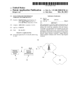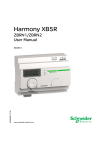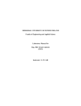
1
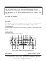
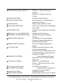
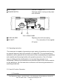
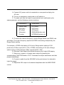
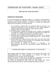
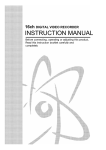
99 Washington Street
Melrose, MA 02176
Fax 781-665-0780
TestEquipmentDepot.com
FG-7002C
Sweep Function Generator
Operation Manual
88 88
WARRANTY
Warranty service covers a period of one year from the date of original purchase.
In case of technical failure within one year, our service center or sales outlet free of
charge will provide repair service.
We charge customers for repair after the one-year warranty period has been
expired. Provided that against any failure resulted from the user’s negligence,
natural disaster or accident, we charge you for repairs regardless of the warranty
period.
For more professional repair service, be sure to contact our service center or sales
outlet.
Introduction
Thank you for purchasing a EZ product. Electronic measuring instruments
produced by EZ Digital are high technology products made under strict quality
control. We guarantee their exceptional precision and utmost reliability. For proper
use of the product, please read this operation manual carefully.
Note
1. To fully maintain the precision and reliability of the product use it within the range
of standard setting( temperature 10 °C~35 °C, humidity 45%~85%)
2. After turning of power, please allow a pre-heating period of as long as some 10
minutes before use.
3. This equipment should be used with a triple line power cord for safety.
4. For quality improvement the exterior design and specification of the product can
be changed without prior notice.
5. If you have further questions concerning use, please contact the EZ Digital
service center or sales outlet
Safety Summary
Please take a moment to read these operating instructions thoroughly and
completely before operating this instrument. Pay particular attention to WARNINGS
used for conditions and actions that pose hazard to the user and CAUTIONS used
for conditions and actions that may damage the instrument.
Always to inspect the instrument and other accessories for any sign of damage
or abnormality before every use.
Never ground yourself and keep your body isolated from ground.
Never touch exposed wiring, connections or any live circuit conductors.
Do not install substitute parts or perform any unauthorized modification to the
instrument.
Use caution when working above 60V DC or 30V AC rms. Such voltages pose
a shock hazard.
Remember that line voltage is present on some power input circuit points such
as on-off switches, fuse, power transformers, etc., even when the equipment is
turn off.
Also, remember that high voltage may appear at unexpected points in defective
equipment.
Test Equipment Depot - 800.517.8431 - 99 Washington Street Melrose, MA 02176
FAX 781.665.0780 - TestEquipmentDepot.com
3
1-1. Introduction
This instrument is the Most Versatile Signal Source used as FUNCTION
GENERATOR, SWEEP GENERATOR, PULSE GENERATOR and a FREQUENCY
COUNTER, offering a wide range of applications in both analog and digital
electronics such as engineering, manufacturing, servicing, education and hobbyist
fields.
VCF(voltage controlled frequency) produces precision sine, square and
triangle waves over the 0.02 Hz to 2 MHz for sub-audible, audio, ultrasonic and RF
applications. A continuously variable DC offset allows the output to be injected
directly into circuits at the correct bias level.
Variable symmetry of the output waveforms converts the instrument to a
pulse generator capable of generating rectangular waves or pulses, ramp or
sawtooth waves and skewed sine waves of variable duty cycle. The sweep
generator offers linear sweep with variable sweep rate and sweep width up to 100:1
frequency change. The frequency response of any active or passive device up to 2
MHz can be determined.
1-2. Technical Specifications
OUTPUT CHARACTERISTICS
Waveforms
: Sine, Square, Triangle, Ramp, Pulse, Sawtooth,
TTL/CMOS Leveled Square, DC
Frequency Range
: 0.02 Hz to 2 MHz in 7 Range(1, 10, 100, 1K, 10K, 100K,
1M)
Frequency Accuracy : ± 5% ( 1, 10 , 100 , 1K , 10K , 100K ,1MHz Range )
(Full Scale)
Output Level
: 20 Vpp in open circuit, 10 Vpp into 50 Ω Load
Output Impedance : 50 Ω ± 5%
Attenuator
: 20 dB fixed and continuously variable
WAVEFORM CHARACTERISTICS
Test Equipment Depot - 800.517.8431 - 99 Washington Street Melrose, MA 02176
FAX 781.665.0780 - TestEquipmentDepot.com
5
Sine wave
Square wave
Triangle wave
TTL Output
CMOS Output
DUTY RATIO
-Flatness
: ± 2.5V to 2 MHz
-Distortion
: Less than 1% at 0.2 Hz to 100 KHz
-Rise and Fall Time : Less than 120 nS
-Linearity
: More than 99% at 0.2 Hz to 100 KHz
-Rise and Fall time : Less than 25 nS
-Output Level
: TTL Level(H 2.4V, L 0.4V)
-Rise and Fall Time : Less than 140 nS(Max. Out)
-Output Level
: 4V to 15V ± 1V, Variable
: 1:1 to 10 : 1
SWEEP FUNCTION CHARACTERISTICS
Mode
Width
Rate
External VCF Input
Input Impedance
: Linear
: Variable from 1 : 1 to 100 : 1
: 0.5 Hz to 50 Hz (20 mS to 2 S)
: Input Voltage : 0 to 10 V
: Approx. 10 KΩ
FREQUENCY COUNTER CHARACTERISTICS
Display
Frequency Range
Accuracy
Time base
Input Sensitivity
Max. Input Voltage
: 6 digit green LED, Gate time, MHz, KHz, Hz, mHz.
: 200 mHz to 50 MHz With Auto Range.
: ± Time base Error ± 1 count
: 10 MHz
: 100 mVrms
: 250 Vpp
DIMENSION AND WEIGHT
Dimension
: 255(W)x 255(D) x90(H)mm
Weight
: Approx. 2.0Kg
1-3. Equipment Ratings
Power
: AC 230V/115V, 50-60 Hz, 15W
Plug and Socket
: 3 wire ac power plug and 3 wire outlet
Test Equipment Depot - 800.517.8431 - 99 Washington Street Melrose, MA 02176
FAX 781.665.0780 - TestEquipmentDepot.com
6
Fuse
: 200mA/250V F Type
Operating Environment
TEMPERATURE : 0 ° C to + 40 ° C
HUMIDITY
:up to 85% to 40° C without
temperature
extremes
causing
condensation within
the instrument.
Storage Environment
TEMPERATURE : -20° C to +70° C
HUMIDITY
: below 85% RH
Insulation Category II: Portable equipment of local level.
Pollution Degree
:2
Protection to IEC 529: Ordinary
1-4. Supplied Accessories
User’s Manual ---------------------------------------------------------------------------- 1
BNC Cable ------------------------------------------------------------------------------
1
Power Cord -----------------------------------------------------------------------------Spare Fuse ------------------------------------------------------------------------------specifications are subject to change without notice.
1
1
2. INSTALLATION
2-1. Initial Inspection
This instrument was carefully inspected both mechanically and electrically before
shipment. It should be physically free of damage. To confirm this, the instrument
should be inspected for physical damage in transit. Also, check for supplied
accessories.
2-2. Connecting AC Power
This instrument requires AC 230V/115V,50-60Hz power through 3-conductor ac
power cable to be fit into three-contact electrical outlet to secure grounding.
If forced to use 2-conductor cable, use ground terminal in rear panel for grounding
instrument.
Test Equipment Depot - 800.517.8431 - 99 Washington Street Melrose, MA 02176
FAX 781.665.0780 - TestEquipmentDepot.com
7
CAUTION
THIS INSTRUMENT IS SET TO AC 230V. BEFORE POWERING ON THIS
INSTRUMENT, MAKE SURE THE VOLTAGE OF THE POWER SOURCE IS AC
230V. IN CASE OF AC115V, SWITCH SHOULD BE SELECTED DOWN TO 115V
POSITION.
2-3. Cooling And Ventilation
No special cooling and ventilation is required. However, the instrument should be
operated where the ambient temperature is maintained.
2-4. Position
This instrument is built as a bench-type instrument with rubber feet and tilt stand in
place. Stand-up angle can be adjusted by rotating angle of carrying handle.
2-5. WARMING-UP
Allow more than 20 minutes for the unit to warm up so that it is stabilized and ready
for use.
3. OPERATION
3-1. Controls, indicators and connectors
FIG 1. FRONT PANEL OPERATOR’S CONTROLS
LED DISPLAY.
Displays Internal Or External
Frequency.
Test Equipment Depot - 800.517.8431 - 99 Washington Street Melrose, MA 02176
FAX 781.665.0780 - TestEquipmentDepot.com
8
INTERNAL/EXTERNAL SWITCH.
PUSH IN
: External Frequency
Counter.
PUSH OUT: Internal Frequency
Counter.
RANGE SWITCHES.
Frequency Range Selector.
FUNCTION SWITCHES.
Select Sine wave, Triangle Wave Or
Square Wave Output.
ATTENUATOR.
Selects Output Level By -20 dB.
GATE TIME INDICATOR.
Gate Time Is Selected Automatically By
Input Signal.
FREQUENCY DIAL.
Controls Output Frequency In Selected
Range.
Indicates Unit Of Frequency.
Used As An External Frequency
Counter.
On-Off Switch For Internal Sweep
Generator, Adjusts Sweep Rate Of
Internal Sweep Generator.
MHz, KHz , Hz, mHz INDICATOR.
EXTERNAL COUNTER INPUT BNC.
SWEEP RATE CONTROL.
SWEEP WIDTH CONTROL.
Pullout And Adjusts Magnitude Of
Sweep.
Voltage Controlled Frequency Input
Permits External Sweep.
Frequency Control Sweep Rate Control
Should Be Off When Applying External
Voltage At This BNC.
Adjust Symmetry Of Output
Waveform 1:1 to 10:1 With Push/Pull
Switch On.
Selects TTL Or CMOS Mode
Pull-out : CMOS Level Control, PushIn: TTL Level.
TTL/CMOS Level Output.
Adds Positive Or Negative DC
Component To Output Signal.
Impedance 50 Ohm.
Adjusts Output Level From 0 TO 20 dB.
VCF INPUT BNC.
SYMMETRY CONTROL.
TTL/CMOS CONTROL.
TTL/CMOS OUTPUT BNC.
DC OFFSET CONTROLS.
MAIN OUTPUT BNC.
AMPLITUDE CONTROL.
Test Equipment Depot - 800.517.8431 - 99 Washington Street Melrose, MA 02176
FAX 781.665.0780 - TestEquipmentDepot.com
9
TILT STAND.
POWER SWITCH.
Pull Out To Adjust Tilt.
Push type switch. turning on the power
when pressed.
VOLTAGE
115V
230V
FUSE
0.5AF
0.25AF
POWER MAX
10W
10W
SN :
115V
22
230V
21
FIG 2. REAR PANEL
FUSE HOLDER.
Replacing fuse with unscrewing
AC INLET.
For connection of the supplied
AC power
3-2. Operating instruction
This instrument is capable of generating a wide variety of waveforms and counting
an external frequency with high resolution of 6 digits LED. The most benefit and
satisfaction can be gained from the instrument by fully understanding its capabilities
and versatility and becoming familiar with operation procedure. One of the best
ways to initially gain this familiarization is to connect the generator to an
oscilloscope. Observe the waveforms and notice the effects of the various controls
on the waveforms. Use this manual as a reference until becoming accustomed to
operating procedures.
3-3. Use As Function Generator.
1) Procedure
Test Equipment Depot - 800.517.8431 - 99 Washington Street Melrose, MA 02176
FAX 781.665.0780 - TestEquipmentDepot.com
10
A. Connect AC power cord into receptacle on rear panel and plug into
AC inlet.
B. To turn on equipment, push power on-off switch on.
C. To make sure that the output is symmetrical and unaffected by the
sweep generator, set the following controls as below.
CONTROLS
POSITION
Sweep width
OFF(push)
Symmetry
OFF(push)
DC offset
OFF(push)
Attenuator
RELEASE(button out)
Counter
INTERNAL(button out)
D. To select the desired frequency, set the Range Switch and FREQ. dial
as follows; The output frequency equals the FREQ. dial setting multiplied by the
Range Switch setting.
For example, a FREQ. dial setting of 0.6 and a Range switch setting of 10K
produces a 6 KHz output(.6x10 = 6K). A FREQ. dial setting of 2.0 and a Range
switch setting of 1M produces 2 MHz output(2.0x1M = 2M).
E. And also it can display the desired frequency by 6 digit LED display.
F. Select sine, square, or triangle wave output by pressing the
corresponding FUNCTION button. FIG 3. illustrates the output waveforms and their
phase relationships.
G. Connect a cable from the 50Ω BNC to the point where it is desired to
inject the signal.
H. Adjust the 50Ω output to the desired amplitude with the AMPLITUDE
control.
Test Equipment Depot - 800.517.8431 - 99 Washington Street Melrose, MA 02176
FAX 781.665.0780 - TestEquipmentDepot.com
11
TTL Pulse
0V
Triangle
0V
Sine
0V
Square
0V
FIG. 3 OUTPUT WAVEFORMS AND PHASE RELATIONSHIPS
I. A positive or negative DC component can be added to the signal at the
50Ω BNC by use of the DC OFFSET control, as required by the circuit into which
the signal is being injected.
J. A fixed amplitude TTL square wave is available at the TTL OUT BNC on
the front panel. This signal is unaffected by the AMPLITUDE, ATTENUATOR or DC
OFFSET. TTL output is a square wave for use in digital circuits, even though
FUNCTION SWITCH is on sine or triangle wave.
2) Considerations
CAUTION
KNOWLEDGE OF THE FOLLOWING FACTORS IS ESSENTIAL FOR PROPER
OPERATION OF THE INSTRUMENT:
A. The DC offset control can provide over ± 10 volts open-circuited, or ± 5
volts into 50Ω load. Remember that the combined signal swing plus DC offset is
also limited to ± 10 V open-circuited, or ± 5 V into 50Ω. Clipping occurs slightly
next page these levels. FIG 4. illustrates the various operating conditions
encountered when using DC offset. If the desired output signal is large or if a large
DC offset is used, an oscilloscope should be used to make sure that the desired
Test Equipment Depot - 800.517.8431 - 99 Washington Street Melrose, MA 02176
FAX 781.665.0780 - TestEquipmentDepot.com
12
combination is
obtained without clipping. Keeping the Amplitude control in the lower half of its
adjustment range reduces the probability of clipping.
B. To set the DC offset to zero or a specific DC voltage, depress the
Function Switches slightly so that all switches are released(all buttons out). This
removes signal from the output and leaves the DC only. Measure the DC output on
an oscilloscope or DC voltmeter and adjust the DC offset control for the desired
value.
C. It is easier to accurately set the FREQ. dial if settings between 0.1 and
2.0 are used. Since the dial rotation overlaps ranges, it is not usually necessary to
use readings below 1. Just change to a lower range and use a higher dial setting.
A. Zero DC Offset
With Maximum Signal
+5V
0V
-5V
B. Offset Limits
Without /Clipping
+5V
0V
-5V
Positive
DC Offset
C. Excessive Offset
+5V
0V
All Example
Output Terminated In 50Ω -5V
Positive
DC Offset
Negative
DC Offset
Negative
DC Offset
FIG 4. USE OF DC OFFSET CONTROL
D. The main output BNC is labeled 50Ω. This means that the source
impedance is 50Ω, but the output may be fed into any circuit impedance. However,
the output level varies in proportion to the terminating impedance. If it is desired to
maintain a constant output level while injecting signal into various circuits with
various impedance, a constant terminating impedance is necessary. When the
Test Equipment Depot - 800.517.8431 - 99 Washington Street Melrose, MA 02176
FAX 781.665.0780 - TestEquipmentDepot.com
13
generator output is connected to a coaxial connector on the equipment under test, it
usually moderate to high impedance. A reasonably constant terminating
impedance may be maintained while injecting signal into moderate and high
impedance circuits(500Ω and up)by adding a coaxial tee in the output cable and
connecting a 50Ω termination to one leg. Remove the 50Ω termination when
injecting into a 50Ω circuit. Also keep DC injection point, the DC offset should be
set to match the circuit voltage, or blocking capacitor may be required to avoid DC
loading with 50Ω.
E. When using the higher output frequencies and when using the square
wave output, terminate the cable in 50Ω to minimize ringing. Keep the cables as
short as possible.
F. To set output amplitude to a specific level, measure peak to peak
amplitude on an oscilloscope.
3-4. Use As Pulse Generator
In a symmetrical square wave, sine wave, or triangle wave, the positive and
negative transitions are of equal time duration, or 1:1 ratio. This is the condition
when the SYMMETRY control off. When the SYMMETRY control is pulled and
rotated, the positive transition can be stretched in relation to the negative transition,
up to at least, 10:1 ratio. Square waves can be stretched into rectangular waves or
pulses, triangle waves can be stretched into distorted wave shape called a skewed
sine wave. FIG 5. illustrates the types of waveforms possible and includes a
summary of control settings used to obtain the desired waveform.
1) Procedure
A. Setup generator as described for function generator operation. Display
the output of generator on an oscilloscope.
B. Select the desired type of waveform with the Function Switches. Press
the square wave button for pulses, triangle button for ramp waves or sine wave
button for skewed sine waves.
Test Equipment Depot - 800.517.8431 - 99 Washington Street Melrose, MA 02176
FAX 781.665.0780 - TestEquipmentDepot.com
14
Adjust Period Of Shorter
Duration With Freq. Controls
Pulse
(Square)
Ramp
(Triangle)
Skewed
(Sine)
FIG 5. PULSE, RAMP, AND SKEWED SINE WAVE GENERATION
C. If both a specific pulse width and repetition rate (specific rise time and
fall time for ramp wave), :are required, The waveform may be obtained as follows:
a. Adjust the shorter duration portion of the waveform(pulse width
for pulse, fall time for ramp waves)with the frequency controls FREQ. dial and
RANGE switch.
b. Adjust the longer duration portion of the waveform(rest time for
pulses, rise time for ramp waves)with the SYMMETRY control.
D. If a specific pulse width (specific fall time for ramp wave)is not critical,
but a specific repetition rate is required, the desired waveform may be obtained as
Adjust Period Of Longer
TTL
follows;
CMOS
Duration With
a. Observe
the oscilloscope and adjust the SYMMETRY control to
Symmetry
Control
obtain the approximate desired
pulse
width vs. rest time ratio(rise time vs. fall time
ratio for ramp waves).
b. Adjust the repetition rate with the frequency controls FREQ. dial
and RANGE switch. the frequency controls affect both the pulse width and
repetition rate.
Test Equipment Depot - 800.517.8431 - 99 Washington Street Melrose, MA 02176
FAX 781.665.0780 - TestEquipmentDepot.com
15
2) Considerations
A. When generating ramp waves or skewed sine waves, it may be easier
to measure the time periods on oscilloscope using the square wave mode, then
switch to the desired operating mode.
B. For ease and accuracy in measurement, use a higher sweep speed on
the oscilloscope to expand the pulse width for measurement, then reduce sweep
speed to measure the repetition rate.
C. Repetition rate may be expressed as a frequency or time period.
Measure the repetition rate as a time period on oscilloscope and convert to
frequency if required. The repetition rate includes the full cycle, both the pulse width
and rest time for pulses, the rise time and fall time for ramp waves.
D. Repetition rate can be measured accurately and easily as a frequency
or time period with a frequency counter.
E. Pulse width also can be measured on a frequency counter, but only with
the SYMMETRY control set off before the pulse waveform is “stretched”. Pulse
width equals one-half the time period of the square wave. If the counter is not
equipped for period measurement, calculate the frequency, which is equivalent to
the desired pulse width, and measure the frequency of the waveform.
1
DESIRED FREQUENCY =
DESIRED PULSE WIDTH x 2
3-5. TTL/CMOS OUTPUT
TTL/CMOS output is specifically designed for compatibility with TTL/CMOS digital
logic circuits. Set-up time is considerably reduced because the fixed logic levels
and polarity are ready for direct injection into TTL/CMOS circuits. there is a need for
protection from accidental Application of too high amplitude or incorrect DC offset
which might damage semiconductors. Another advantage is the extremely fast rise
time and fall time of signal. To use the TTL/CMOS output, connect a cable from
TTL/CMOS BNC on the Front panel to the point at which it is desired to inject the
signal. TL/CMOS output may be used in several modes of operation. Some
examples follow.
Test Equipment Depot - 800.517.8431 - 99 Washington Street Melrose, MA 02176
FAX 781.665.0780 - TestEquipmentDepot.com
16
A. Using the square wave generator or pulse generator modes, clock
pulses can be generated for testing, troubleshooting or circuit analysis. The
instrument could even be used as a substitute master clock generator as
TTL/CMOS circuits can be driven from the TTL/CMOS BNC.
B. The CMOS Level Control potentiometer (pull out position) provides
CMOS level output from 5V to 15V Variable and Continuously. For TTL/CMOS
output level, Rotate the potentiometer switch and Observe the TTL or CMOS
output : Push-in is TTL, Pull-out is CMOS.
3-6. Use As FM Signal Generator
1) Procedure
A. Set up equipment as described for function generator operation. Use
the frequency and amplitude controls to set the carrier to the desired frequency
and amplitude.
B. Connect an AC modulating signal with no DC component to the VCF IN
BNC on the front panel of generator.
C. Adjust amplitude of the AC modulating signal for the desired frequency
deviation.
2) Considerations
A. The approximate frequency deviation for a given VCF IN signal can be
determined as follows,
The 0.1 V change at the VCF IN BNC produces a frequency change of 1% of the
highest frequency obtainable on a given range. For example, the highest frequency
obtainable on the 100 K range is 200 KHz. One percent of 200 KHz equals 2 KHz.
Therefore, 0.1 V change at the VCF IN BNC will deviate the output frequency 2
KHz on the 100K range. Following table summarizes the frequency deviation
versus VCF IN voltage for all ranges.
Test Equipment Depot - 800.517.8431 - 99 Washington Street Melrose, MA 02176
FAX 781.665.0780 - TestEquipmentDepot.com
17
RANGE
HIGHEST FREQ.
OBTAINABLE(Hz)
FREQ. DEVIATION FOR EACH
0.1 VOLT VCF IN CHANGE(Hz)
1
10
100
1K
10K
100K
1M
2
20
200
2K
20K
200K
2M
0.02
0.2
2
20
200
2K
20K
Frequency deviation versus VCF IN voltage.
B. For an example, it is assumed that we wish to generate a 455 KHz
signal with FM deviation of ± 15 KHz (30 KHz swing). 1M range will be used to
obtain the 455 KHz carrier with the FREQ. dial set to 0.455. The highest frequency
obtainable on the 1M range is 2 MHz. One percent of 2 MHz is 20 KHz. Our
requirement of 30 KHz deviation is 1.5 times greater than 20 KHz deviation
produced by a 0.1 volt VCF IN swing, thus we will use 1.5 times as much peak-topeak voltage swing, or 0.15 V.
STATED ANOTHER WAY:
EXAMPLE:
desired deviation
x0.1 V = required VCF IN signal
1% deviation
SUBSTITUTING THIS
30 KHz x 0.1 = 1.5 x 0.1V = 0.15V
20 KHz
C. Remember that the value of VCF IN signal is the peak to peak
amplitude.
3-7. External Control Of VCF
Within a given range, the FREQ. dial setting normally controls the output
frequency of generator. However, applying voltage at the VCF IN BNC on the front
panel also may control it. There are three basic possible modes of external VCF
control as detailed below,
A. Applying an AC voltage produces FM modulation(previously described
Test Equipment Depot - 800.517.8431 - 99 Washington Street Melrose, MA 02176
FAX 781.665.0780 - TestEquipmentDepot.com
18
in “Use as FM Signal Generator” paragraph)
B. Applying a specific fixed DC voltage will produce a specific output
frequency described in following “Programmed Frequency Selection”paragraph)
C. Applying a ramp voltage(or other type waveform if desired)provides
externally controlled sweep generator operation(described in following “Use as
Externally Controlled Sweep Generator” paragraph)
The following consideration apply to all modes of operation involving external
control of the VCF(voltage controlled frequency)
A. The output frequency of generator is determined by the voltage applied
to the VCF. First of all, this voltage is established by the setting of the FREQ. dial.
Any voltage input drives the VCF TO A HIGHER FREQUENCY. However. The VCF
can never be driven beyond its range limits (the highest and lowest frequencies that
can be attained with the dial on a given range.)
B. With the FREQ. dial set at minimum(0.02) and 0 volts at the VCF in
BNC, the generator output frequency is at the lower limit of the selected range.
Increasing the voltage to + 10 volts drives the generator frequency to the upper limit
of the range. Between 0 and + 10 Volts, the generator output frequency is
proportional to the VCF IN voltage. The VCF IN voltage can be correlated to
equivalent dial settings as given in Table below.
VCF voltage
Equivalent dial Setting
0
0.02
1
.2
2
.4
3
.6
4
.8
5
1.0
6
.12
7
1.4
8
1.6
9
1.8
10
2.0
Correlation between VCF IN voltage and equivalent dial setting(dial set to 0.02)
C. The FREQ. dial is usually set to 0.02 when using external VCF control.
This reduces the dialed VCF voltage to zero and allows the external VCF voltage to
exercise complete control. It also reduces the effects of dial setting inaccuracy.
D. If the summed dial setting and VCF IN voltage exceeds +10 volts,
oscillation ceases and no output is produced. If the swing of the VCF IN signal is
Test Equipment Depot - 800.517.8431 - 99 Washington Street Melrose, MA 02176
FAX 781.665.0780 - TestEquipmentDepot.com
19
too great, oscillation will cease each time the instantaneous voltage reaches the
limit.
3-8. Programmed Frequency Selection
A specific output frequency can be selected each time a specific VCF input
voltage is applied(assuming a common dial setting). Such operation may
be advantageous where there is a requirement to return to a specific
frequency periodically. Eliminating the need for frequency measurement
reduces set-up time and precision tuning each time frequency is needed.
Just set the dial against its lower stop and turn on the external VCF voltage.
Using multiple DC voltage values, which may be selected by a switch or
electronic switching circuits, may program a set of two or more specific
frequencies. This type of operation would be desirable in production testing
where signals at several specific frequencies are required for various tests.
FSK(frequency shift keying)signals also may be generated in this manner.
To maintain the original accuracy each time the operation is repeated, the
FREQ. dial must be accurately set to the same position. Probably the
easiest way to assure this common dial setting is to set it against its lower
stop(0.02). Additional information on programmed frequency selection is
given in APPLICATIONS chapter of this manual.
3-9. Use As Sweep Generator
1) Procedure
A. Set up equipment as for function generator operation.
B. Select the highest frequency to be swept with RANGE switch and the
lowest frequency to be swept with FREQ. dial.
C. Adjust amount of sweep with the sweep rate control.
D. Adjust repetition rate of sweep with the sweep rate control.
2) Considerations
0.02 or low FREQ. dial setting is recommended for most sweep generator
operation. The dial setting determines the lowest frequency of generator. The
sweep generator will sweep upward from that point. However, it will sweep upward
only to the range limit(highest frequency to which the dial can tune on the selected
range). Therefore, a low dial setting is required to obtain a sweep covering a wide
Test Equipment Depot - 800.517.8431 - 99 Washington Street Melrose, MA 02176
FAX 781.665.0780 - TestEquipmentDepot.com
20
frequency range. The 0.02 setting must be used to obtain the maximum sweep
width of 100:1(highest frequency sweep is 100 times that of lowest frequency
swept).If a high dial setting and high SWEEP WIDTH setting are used
simultaneously, the generator will sweep to the range limit and ceases operation for
a portion of the sweep cycle, effectively clipping the sweep. Of course, if only a
small frequency band is to be swept, a low dial setting is not important. In fact, it
may be easier to set to the desired frequencies if the dial setting is 0.1 or higher.
3-10. Use As Externally Controlled Sweep Generator
A ramp voltage, or any other type waveform desired, can be applied for externally
controlled sweep generator operation. 0 to 10 volt swing will sweep frequencies
over a 100:1 ratio(with dial set to 0.02) Set up the instrument as described for
internally controlled sweep generator operation, except turn the SWEEP WIDTH
control to OFF. Apply the sweep voltage with no DC component at the VCF Input
BNC. Set the FREQ. dial to the highest frequency to be swept and apply a
negative-going ramp voltage.
3-11. Use As External Frequency Counter
1) USE AS EXTERNAL FREQUENCY COUNTER
A. EXTERNAL AND INTERNAL COUNTER SELECTION
This instrument can be used as a counter by Push-in of INT/EXT selection switch.
B. EXT COUNT IN BNC accepts external frequency input.
C. COUNTER DISPLAY
Input frequency is displayed with high resolution on a 6 digit LED display.
D. mHz, Hz, KHz, MHz INDICATOR
mHz, Hz, KHz, MHz indicators & decimal points display the max. 50 MHz of
external frequency.
E. PUSHED-IN FREQ.RANGE S.W X1.
Test Equipment Depot - 800.517.8431 - 99 Washington Street Melrose, MA 02176
FAX 781.665.0780 - TestEquipmentDepot.com
21
CAUTION
1. APPLICATION OF INPUT VOLTAGES HIGHER THAN THE LIMITS LISTED IN
THE SPECIFICATIONS SECTION MAY DAMAGE THE COUNTER. BEFORE
APPLYING ANY SIGNAL TO THE INPUTS, MAKE CERTAIN THAT IT DOES NOT
EXCEED THESE SPECIFIED MAXIMUMS.
2. FREQUENCY COUNTER GROUND POINTS ARE CONNECTED DIRECTLY TO
EARTH GROUND. ALWAYS CONNECT FREQUENCY COUNTER GROUND
ONLY TO GROUND POINTS IN THE CIRCUIT UNDER TES
4. MAINTENANCE
CAUTION
IT IS ESSENTIAL FOR SAFETY TO PROPERLY MAINTAIN AND SERVICE THIS
INSTRUMENT
WARNING
VOLTAGES WITHIN THIS INSTRUMENT ARE SUFFICIENTLY HIGH TO
ENDANGER LIFE. COVERS MUST NOT BE REMOVED EXCEPT BY PERSONS
QUALIFIED AND AUTHORIZED TO DO SO AND THESE PERSONS SHOULD
ALWAYS TAKE EXTREME CARE ONCE THE COVERS HAVE BEEN REMOVED.
4-1. Fuse replacement
Disconnect and remove all connections from any live power source.
Unscrew fuse holder by screw driver.
Locate the defective fuse and remove it by gently pulling-out.
Install a new fuse of the SAME SIZE AND RATING.
Screwing fuse holder.
Test Equipment Depot - 800.517.8431 - 99 Washington Street Melrose, MA 02176
FAX 781.665.0780 - TestEquipmentDepot.com
22
This instrument can be used to provide information regarding the input impedance
of a speaker or any other impedance network vs. frequency. In addition, the
resonant frequency of the network can be determined.
A. Connect equipment as shown in Test Set-Up in FIG. 8 for frequency
response measurement except that the signal input to the speaker or impedance
network is monitored. The oscilloscope may be used to verify that this instrument is
not in a clipping condition.
B. If the voltmeter method is used, vary the range over the full range of
interest and log the voltage measured at the speaker terminals vs. Frequency. The
dB scales of the AC voltmeter are convenient for converting this information to
standard response units.
C. If the oscilloscope method is used, use sweep operation as for
frequency response measurement.
D. In speaker testing, a pronounced increase of voltage will occur at some
low frequency. This is the resonance frequency of the speaker systems(FIG. 8).
The speaker enclosure will modify the results obtained from the same speaker
without an enclosure. A properly designed enclosure will produce a small peak on
each side of the peak obtained without an enclosure. the enclosure designer can
use the response characteristics to evaluate the effects of varying port sizes,
damping materials and other basic enclosure factors.
E. In testing other impedance networks resonance will not necessarily
occur at low frequency. However, as resonance is approached the signal level will
increase. The impedance of the network can be measured at resonance, or at other
frequencies if desired as follows:
1) Connect a variable resistor in series with the impedance
network as shown in FIG. 8
2) Measure the voltage at points E1 and E2 respectively and
adjust variable resistor R1 so that voltage E2 equals one half of voltage E1
5-7. Digital Frequency Selection
Test Equipment Depot - 800.517.8431 - 99 Washington Street Melrose, MA 02176
FAX 781.665.0780 - TestEquipmentDepot.com
29
CAUTION
MAKE SURE THAT THE RATED AND SPECIFIED FUSES ARE USED FOR
REPLACEMENT.
4-2. Adjustment and calibration
It is recommendable to regularly adjust and calibrate this instrument. Qualified and
authorized personnel only should execute performance and procedures
4-3. Cleaning and decontamination
The instrument can be cleaned with a soft clean cloth to remove any oil, grease or
grime. Never use liquid solvents or detergents. If the instrument gets wet for any
reason, dry the instrument using low pressure clean air at less than 25 PSI. Use
care and caution around the window cover areas where water or air could enter into
the instrument while drying.
5. OTHERS
5-1. Introduction
Because of the great versatility of this Sweep/Function Generator, it would be
impossible to include all of its possible applications in this manual, However ,many
of the primary applications are described in detail to allow the user to adapt the
procedures to other applications. The instrument has vast numbers of applications
as a signal source in electronics design labs, classrooms, service shops and
production facilities to test or analyze audio, radio, digital, communications, medical
electronics, sonar, industrial electronics, subsonic, ultrasonic and many other
electronic devices and circuits.
5-2. Troubleshooting By Signal Substitution
When troubleshooting dead audio equipment, localize the trouble by injecting an
audio signal from Sweep/Function Generator to substitute for the normal signal.
Starting at the nearest speaker and moving toward the audio input area, Step By
Step, sound will be heard from the speaker for each stage that is operating normally.
Test Equipment Depot - 800.517.8431 - 99 Washington Street Melrose, MA 02176
FAX 781.665.0780 - TestEquipmentDepot.com
23
When signal is applied to the defective stage, no sound will be heard from the
speaker.
CAUTION
MAKE SURE THE DC OFFSET MATCHES THE NORMAL OPERATING
VOLTAGE AT EACH POINT OF SIGNAL INJECTION. IMPROPER DC OFFSET
COULD BIAS A NORMALLY OPERATING STAGE TO CUT OFF AND MAKE IT
APPEAR DEFECTIVE. IMPROPER DC OFFSET COULD ALSO DAMAGE
CERTAIN CIRCUITS. A COUPLING CAPACITOR MAY BE USED TO BLOCK THE
DC OFFSET AND ALLOW THE SIGNAL TO FLOAT AT THE DC LEVEL OF THE
POINT OF INJECTION IF DESIRED.
The signal amplitude should also simulate the normal signal levels used in the
circuit where signal is being injected. This technique is equally applicable to non
audio equipment. Just connect an oscilloscope, voltmeter, or any other device,
which will indicate the presence or absence of output. Inject the type of signal
normally used by the equipment being tested. This instrument can generate almost
any type of signal normally required in the 0.02 Hz to 2 MHz range. If the equipment
under test, It can generate unique sounds or signals by means of sweep that should
be easily distinguishable from any other signals that may be present.
5-3. Troubleshooting By Signal Tracing
This technique is similar to “Troubleshooting by Signal Substitution” except that the
signal is injected at the input of the equipment under test. An oscilloscope is then
used to check for output at each stage, starting nearest at the input area and
moving toward to the output area. Each stage, which has no output, is presumed to
be defective.
5-4. Amplifier Overload Characteristics
The overload point for some amplifiers is difficult to determine by using sinewave
input. The triangle waveform is ideal for this type of test because any departure
Test Equipment Depot - 800.517.8431 - 99 Washington Street Melrose, MA 02176
FAX 781.665.0780 - TestEquipmentDepot.com
24
from absolute linearity is readily detectable. By using the triangle output, the peak
overload condition for an amplifier can be readily determined. This overload
condition is shown in shown in FIG 6.
Input Waveform
Output Waveform
FIG 6. Amplifier overload characteristics
5-5. Amplifier Performance Evaluation Using Square Waves
The standard sinewave frequency reopens curves do not give a full evaluation of
the amplifier transient response. the square wave, because of the high harmonic
content, yields much information regarding amplifier performance when used in
conjunction with an oscilloscope.
A. Use the test set-up of FIG 7. The 50Ω termination at the amplifier input
is essential when using square waves to eliminate the ringing effects generated by
the fast rise times.
B. Using the triangle output, set the AMPLITUDE control so that there is no
signal clipping over the range of frequencies to be used.
Test Equipment Depot - 800.517.8431 - 99 Washington Street Melrose, MA 02176
FAX 781.665.0780 - TestEquipmentDepot.com
25
B. Select the square wave output and adjust the frequency to several
check points within the pass band of the amplifier such as 20 Hz, 1000
Hz and
10 KHz.
C. At each frequency checkpoint, the waveform obtained at the amplifier
output provides information regarding amplifier performance with
respect to the frequency of square wave input. FIG 7. indicates the
possible waveforms obtained
at the amplifier output. Square wave evaluation is not practical for narrow-band
amplifiers. The restricted bandwidth of the amplifier cannot reproduce all frequency
components of the square wave in the proper phase and amplitude relationships.
Dual Trace Oscilloscope Preferred
Square Wave Selected
Test Equipment Depot - 800.517.8431 - 99 Washington Street Melrose, MA 02176
FAX 781.665.0780 - TestEquipmentDepot.com
26
FIG 7. AMPLIFIER PERFORMANCE EVALUATION USING SQUARE WAVES.
Test Equipment Depot - 800.517.8431 - 99 Washington Street Melrose, MA 02176
FAX 781.665.0780 - TestEquipmentDepot.com
A. Test Set-up
Test Equipment Depot - 800.517.8431 - 99 Washington Street Melrose, MA 02176
FAX 781.665.0780 - TestEquipmentDepot.com
27
B. Equivalent Circuit Of Test Set-Up
GENERATOR
C. Graph Of Results
GENERATOR
FIG 8. TESTING SPEAKER SYSTEMS AND IMPEDANCE NETWORKS.
5-6. Testing Speakers And Impedance Networks
Test Equipment Depot - 800.517.8431 - 99 Washington Street Melrose, MA 02176
FAX 781.665.0780 - TestEquipmentDepot.com
28
Frequencies can be switched electronically by using the set-up shown in FIG. 9.
The preset voltages can be digitally selected and applied to the VCF IN BNC.
Although provision for two frequencies are shown, additional frequencies can be
added using redundant circuits. This is convenient in frequency shift keying(FSK)
systems.
FIG 9. DIGITALLY PROGRAMMED FREQUENCY SELECTION
5-8. Additional Applications
The triangle or ramp output of this instrument can be used at its lowest frequencies
to simulate a slowly varying DC source. This can be used to check threshold levels
of TTL and CMOS logic as well as voltage compactors can be exercised from zero
to full scale to observe defective deflection such as sticky meter movements.
Test Equipment Depot - 800.517.8431 - 99 Washington Street Melrose, MA 02176
FAX 781.665.0780 - TestEquipmentDepot.com
30