1
WORK ORDER NO. 1127117
APPROPRIATION: O&MN
Repairs to Submarine A School BQ 534
At
Naval Submarine Base
New London, CT
VOLUME III of III
Division 26 – Division 34
SUBMITTED BY:
NAVFAC ML NEIPT
Bldg Z144
9742 Maryland Ave.
Norfolk Naval Station
Norfolk, Virginia
PREPARED BY:
Project Manager:
Civil:
Structural:
Interior:
Fire Protection:
Plumbing:
Mechanical:
Electrical:
Roger Schalge, NAVFAC ML NEIPT
Vince Hill, PE; NAVAC ML NEIPT
Brian Felker, PE; NAVAFAC ML NEIPT
Alison Roan, NAVAC ML NEIPT
Patrick Bakaj, PE; NAVFAC ML
Joe Smith, PE; NAVAC ML NEIPT
Joe Smith, PE; NAVAC ML NEIPT
Chris Vidal, PE; NAVAFAC ML NEIPT
Lead Engineer:
Nancy Wroten
NAVFAC ML NEIPT
Date: 11JUNE2012
APPROVED BY:
For Commander, NAVFAC Mid-Atlantic
Engineering Director: James E. Donahue, R.A.
Northeast IPT Capital Improvements
James E. Donahue, R.A.
Submarine A School BQ 534
1127117
PROJECT TABLE OF CONTENTS
DIVISION 00 - PROCUREMENT AND CONTRACTING REQUIREMENTS
00 01 15
LIST OF DRAWINGS
DIVISION 01 - GENERAL REQUIREMENTS
01
01
01
01
01
01
01
01
01
01
01
01
01
01
01
01
01
01
01
01
11
14
20
30
32
32
33
35
35
42
45
50
57
58
62
74
75
78
78
78
00
00
00.00
00
01.00
17.00
00
26
40.00
00
00.00
00
19.00
00
35
19
00
00
23
24.00
20
10
20
20
20
20
20
SUMMARY OF WORK
WORK RESTRICTIONS
PRICE AND PAYMENT PROCEDURES
ADMINISTRATIVE REQUIREMENTS
PROJECT SCHEDULE
NETWORK ANALYSIS SCHEDULES (NAS)
SUBMITTAL PROCEDURES
GOVERNMENTAL SAFETY REQUIREMENTS
ENVIRONMENTAL MANAGEMENT
SOURCES FOR REFERENCE PUBLICATIONS
QUALITY CONTROL
TEMPORARY CONSTRUCTION FACILITIES AND CONTROLS
TEMPORARY ENVIRONMENTAL CONTROLS
PROJECT IDENTIFICATION
RECYCLED / RECOVERED MATERIALS
CONSTRUCTION AND DEMOLITION WASTE MANAGEMENT
STARTING AND ADJUSTING
CLOSEOUT SUBMITTALS
OPERATION AND MAINTENANCE DATA
FACILITY ELECTRONIC OPERATION AND MAINTENANCE SUPPORT
INFORMATION (eOMSI)
DIVISION 02 - EXISTING CONDITIONS
02 82 16.00 20
02 83 13.00 20
02 84 16
02 85 00.00 20
ENGINEERING CONTROL OF ASBESTOS CONTAINING MATERIALS
LEAD IN CONSTRUCTION
HANDLING OF LIGHTING BALLASTS AND LAMPS CONTAINING PCBs
AND MERCURY
MOLD REMEDIATION
DIVISION 03 - CONCRETE
03 30 00
CAST-IN-PLACE CONCRETE
DIVISION 05 - METALS
05
05
05
05
05
05
12
40
50
51
51
52
00
00
13
00
33
00
STRUCTURAL STEEL
COLD-FORMED METAL FRAMING
MISCELLANEOUS METAL FABRICATIONS
METAL STAIRS
METAL LADDERS
METAL RAILINGS
DIVISION 06 - WOOD, PLASTICS, AND COMPOSITES
06 10 00
06 41 16.00 10
06 61 16
ROUGH CARPENTRY
LAMINATE CLAD ARCHITECTURAL CASEWORK
SOLID POLYMER (SOLID SURFACING) FABRICATIONS
DIVISION 07 - THERMAL AND MOISTURE PROTECTION
PROJECT TABLE OF CONTENTS Page 1
Submarine A School BQ 534
07
07
07
07
07
07
07
21
22
52
60
81
84
92
23
00
00
00
00
00
00
LOOSE FILL THERMAL INSULATION
ROOF AND DECK INSULATION
MODIFIED BITUMINOUS MEMBRANE ROOFING
FLASHING AND SHEET METAL
SPRAY-APPLIED FIREPROOFING
FIRESTOPPING
JOINT SEALANTS
DIVISION 08 - OPENINGS
08
08
08
08
08
08
08
11
14
41
51
71
81
91
13
00
13
13
00
00
00
STEEL DOORS AND FRAMES
WOOD DOORS
ALUMINUM-FRAMED ENTRANCES AND STOREFRONTS
ALUMINUM WINDOWS
DOOR HARDWARE
GLAZING
METAL WALL AND DOOR LOUVERS
DIVISION 09 - FINISHES
09
09
09
09
09
09
09
09
09
09
22
29
30
51
65
66
67
68
72
90
00
00
00
00
00
23.00 22
23.13
00
00
00
SUPPORTS FOR PLASTER AND GYPSUM BOARD
GYPSUM BOARD
CERAMIC TILE, QUARRY TILE, AND PAVER TILE
ACOUSTICAL CEILINGS
RESILIENT FLOORING
RESINOUS (EPOXY) TERRAZZO FLOORING
STANDARD RESINOUS FLOORING
CARPET
WALL COVERINGS
PAINTS AND COATINGS
DIVISION 10 - SPECIALTIES
10
10
10
10
10
14
21
26
28
44
02
13
13
13
16
INTERIOR SIGNAGE
TOILET AND SHOWER COMPARTMENTS
WALL AND CORNER GUARDS
TOILET ACCESSORIES
FIRE EXTINGUISHERS
DIVISION 12 - FURNISHINGS
12 24 13
12 48 13.13
ROLLER WINDOW SHADES
ENTRANCE FLOOR MATS
DIVISION 14 - CONVEYING EQUIPMENT
14 21 23
ELECTRIC TRACTION PASSENGER ELEVATORS
DIVISION 21 - FIRE SUPPRESSION
21 13 13.00 20
WET PIPE SPRINKLER SYSTEM, FIRE PROTECTION
DIVISION 22 - PLUMBING
22
22
22
22
00
05
07
14
00
83.63
19
29
PLUMBING, GENERAL PURPOSE
CURED-IN-PLACE PIPE (CIPP) LINING
PLUMBING PIPING INSULATION
SUMP PUMPS
PROJECT TABLE OF CONTENTS Page 2
1127117
Submarine A School BQ 534
1127117
DIVISION 23 - HEATING, VENTILATING, AND AIR CONDITIONING
23
23
23
23
23
23
23
23
23
23
23
00
03
05
05
07
08
09
09
11
23
81
00
00.00
15
93
00
00.00
23.13
53.00
25
00
28.10
20
10
20
20
22
AIR SUPPLY, DISTRIBUTION, VENTILATION, AND EXHAUST SYSTEMS
BASIC MECHANICAL MATERIALS AND METHODS
COMMON PIPING FOR HVAC
TESTING, ADJUSTING, AND BALANCING FOR HVAC
THERMAL INSULATION FOR MECHANICAL SYSTEMS
COMMISSIONING OF HVAC SYSTEMS
BACnet DIRECT DIGITAL CONTROL SYSTEMS FOR HVAC
SPACE TEMPERATURE CONTROL SYSTEMS
FACILITY GAS PIPING
REFRIGERANT PIPING
VARIABLE REFRIGERANT FLOW (VRF) MULTI-SPLIT AIR
CONDITIONING AND HEAT PUMP EQUIPMENT
DIVISION 26 - ELECTRICAL
26
26
26
26
26
26
26
26
26
00
08
12
20
23
27
29
41
51
00.00 20
00
19.10
00
00
14.00 20
23
00.00 20
00
BASIC ELECTRICAL MATERIALS AND METHODS
APPARATUS INSPECTION AND TESTING
THREE-PHASE PAD-MOUNTED TRANSFORMERS
INTERIOR DISTRIBUTION SYSTEM
SWITCHBOARDS
ELECTRICITY METERING
VARIABLE FREQUENCY DRIVE SYSTEMS UNDER 600 VOLTS
LIGHTNING PROTECTION SYSTEM
INTERIOR LIGHTING
DIVISION 27 - COMMUNICATIONS
27 10 00
BUILDING TELECOMMUNICATIONS CABLING SYSTEM
DIVISION 28 - ELECTRONIC SAFETY AND SECURITY
28 31 63.00 20
ANALOG/ADDRESSABLE INTERIOR FIRE ALARM SYSTEM
DIVISION 31 - EARTHWORK
31 00 00
31 05 22
EARTHWORK
GEOTEXTILES USED AS FILTERS
DIVISION 32 - EXTERIOR IMPROVEMENTS
32
32
32
32
32
32
01
01
01
12
12
12
13
16.17
17.16
10
17
19
32 16 13
32 17 23.00 20
32 92 19
BITUMINOUS SEAL AND FOG COATS
COLD MILLING OF BITUMINOUS PAVEMENTS
SEALING OF CRACKS IN BITUMINOUS PAVEMENTS
BITUMINOUS TACK AND PRIME COATS
HOT MIX BITUMINOUS PAVEMENT
BITUMINOUS BINDER AND WEARING COURSES (CENTRAL-PLANT
COLD-MIX)
CONCRETE SIDEWALKS AND CURBS AND GUTTERS
PAVEMENT MARKINGS
SEEDING
DIVISION 33 - UTILITIES
33
33
33
33
12
40
51
71
33.00
00.00
13.00
02.00
30
40
30
20
WATER UTILITY METERING
STORM DRAINAGE UTILITIES
NATURAL-GAS METERING
UNDERGROUND ELECTRICAL DISTRIBUTION
PROJECT TABLE OF CONTENTS Page 3
Submarine A School BQ 534
DIVISION 34 - TRANSPORTATION
34 41 26.00 10
ACCESS CONTROL POINT CONTROL SYSTEM
-- End of Project Table of Contents --
PROJECT TABLE OF CONTENTS Page 4
1127117
Submarine A School BQ 534
1127117
SECTION 26 00 00.00 20
BASIC ELECTRICAL MATERIALS AND METHODS
07/06
PART 1
1.1
GENERAL
REFERENCES
The publications listed below form a part of this specification to the
extent referenced. The publications are referred to in the text by the
basic designation only.
ASTM INTERNATIONAL (ASTM)
ASTM D 709
(2001; R 2007) Laminated Thermosetting
Materials
INSTITUTE OF ELECTRICAL AND ELECTRONICS ENGINEERS (IEEE)
IEEE 100
(2000; Archived) The Authoritative
Dictionary of IEEE Standards Terms
IEEE C2
(2012) National Electrical Safety Code
IEEE C57.12.28
(2005) Standard for Pad-Mounted Equipment
- Enclosure Integrity
IEEE C57.12.29
(2005) Standard for Pad-Mounted Equipment
- Enclosure Integrity for Coastal
Environments
NATIONAL ELECTRICAL MANUFACTURERS ASSOCIATION (NEMA)
NEMA 250
(2008) Enclosures for Electrical Equipment
(1000 Volts Maximum)
NATIONAL FIRE PROTECTION ASSOCIATION (NFPA)
NFPA 70
1.2
(2011; TIA 11-1; Errata 2011) National
Electrical Code
RELATED REQUIREMENTS
This section applies to certain sections of Division 02, EXISTING CONDITIONS
Divisions 22 and 23, PLUMBING and HEATING VENTILATING AND AIR CONDITIONING.
This section applies to all sections of Division 26 and 33, ELECTRICAL and
UTILITIES, of this project specification unless specified otherwise in the
individual sections. This section has been incorporated into, and thus,
does not apply to, and is not referenced in the following sections.
Section 26 12 19.10 THREE-PHASE PAD MOUNTED TRANSFORMERS
Section 26 20 00 INTERIOR DISTRIBUTION SYSTEM
Section 26 23 00 SWITCHBOARDS AND SWITCHGEAR
Section 26 51 00 INTERIOR LIGHTING
Section 27 10 00 BUILDING TELECOMMUNICATIONS CABLING SYSTEM
SECTION 26 00 00.00 20
Page 1
Submarine A School BQ 534
1127117
Section 33 71 02.00 20 UNDERGROUND ELECTRICAL DISTRIBUTION
1.3
DEFINITIONS
a.
Unless otherwise specified or indicated, electrical and electronics
terms used in these specifications, and on the drawings, shall be as
defined in IEEE 100.
b.
The technical sections referred to herein are those specification
sections that describe products, installation procedures, and equipment
operations and that refer to this section for detailed description of
submittal types.
c.
The technical paragraphs referred to herein are those paragraphs in
PART 2 - PRODUCTS and PART 3 - EXECUTION of the technical sections that
describe products, systems, installation procedures, equipment, and
test methods.
1.4
ELECTRICAL CHARACTERISTICS
Electrical characteristics for this project shall be 13.8 kV primary, three
phase, three wire, 60 Hz, and 208Y/120 volts secondary, three phase, four
wire.
Final connections to the power distribution system at the existing
pad-mount trasformer location using the existing primary feeders shall be
made by the Contractor.
1.5
ADDITIONAL SUBMITTALS INFORMATION
Submittals required in other sections that refer to this section must
conform to the following additional requirements as applicable.
1.5.1
Shop Drawings (SD-02)
Include wiring diagrams and installation details of equipment indicating
proposed location, layout and arrangement, control panels, accessories,
piping, ductwork, and other items that must be shown to ensure a
coordinated installation. Wiring diagrams shall identify circuit terminals
and indicate the internal wiring for each item of equipment and the
interconnection between each item of equipment. Drawings shall indicate
adequate clearance for operation, maintenance, and replacement of operating
equipment devices.
1.5.2
Product Data (SD-03)
Submittal shall include performance and characteristic curves.
1.6
1.6.1
QUALITY ASSURANCE
Regulatory Requirements
In each of the publications referred to herein, consider the advisory
provisions to be mandatory, as though the word, "shall" had been
substituted for "should" wherever it appears. Interpret references in
these publications to the "authority having jurisdiction," or words of
similar meaning, to mean the Contracting Officer. Equipment, materials,
installation, and workmanship shall be in accordance with the mandatory and
advisory provisions of NFPA 70 unless more stringent requirements are
specified or indicated.
SECTION 26 00 00.00 20
Page 2
Submarine A School BQ 534
1.6.2
1127117
Standard Products
Provide materials and equipment that are products of manufacturers
regularly engaged in the production of such products which are of equal
material, design and workmanship. Products shall have been in satisfactory
commercial or industrial use for 2 years prior to bid opening. The 2-year
period shall include applications of equipment and materials under similar
circumstances and of similar size. The product shall have been on sale on
the commercial market through advertisements, manufacturers' catalogs, or
brochures during the 2-year period. Where two or more items of the same
class of equipment are required, these items shall be products of a single
manufacturer; however, the component parts of the item need not be the
products of the same manufacturer unless stated in the technical section.
1.6.2.1
Alternative Qualifications
Products having less than a 2-year field service record will be acceptable
if a certified record of satisfactory field operation for not less than
6000 hours, exclusive of the manufacturers' factory or laboratory tests, is
furnished.
1.6.2.2
Material and Equipment Manufacturing Date
Products manufactured more than 3 years prior to date of delivery to site
shall not be used, unless specified otherwise.
1.7
WARRANTY
The equipment items shall be supported by service organizations which are
reasonably convenient to the equipment installation in order to render
satisfactory service to the equipment on a regular and emergency basis
during the warranty period of the contract.
1.8
POSTED OPERATING INSTRUCTIONS
Provide for each system and principal item of equipment as specified in the
technical sections for use by operation and maintenance personnel. The
operating instructions shall include the following:
a.
Wiring diagrams, control diagrams, and control sequence for each
principal system and item of equipment.
b.
Start up, proper adjustment, operating, lubrication, and shutdown
procedures.
c.
Safety precautions.
d.
The procedure in the event of equipment failure.
e.
Other items of instruction as recommended by the manufacturer of each
system or item of equipment.
Print or engrave operating instructions and frame under glass or in
approved laminated plastic. Post instructions where directed. For
operating instructions exposed to the weather, provide weather-resistant
materials or weatherproof enclosures. Operating instructions shall not
fade when exposed to sunlight and shall be secured to prevent easy removal
or peeling.
SECTION 26 00 00.00 20
Page 3
Submarine A School BQ 534
1.9
1127117
MANUFACTURER'S NAMEPLATE
Each item of equipment shall have a nameplate bearing the manufacturer's
name, address, model number, and serial number securely affixed in a
conspicuous place; the nameplate of the distributing agent will not be
acceptable.
1.10
FIELD FABRICATED NAMEPLATES
ASTM D 709. Provide laminated plastic nameplates for each equipment
enclosure, relay, switch, and device; as specified in the technical
sections or as indicated on the drawings. Each nameplate inscription shall
identify the function and, when applicable, the position. Nameplates shall
be melamine plastic, 0.125 inch thick, white with black center core.
Surface shall be matte finish. Corners shall be square. Accurately align
lettering and engrave into the core. Minimum size of nameplates shall be
one by 2.5 inches. Lettering shall be a minimum of 0.25 inch high normal
block style.
1.11
WARNING SIGNS
Provide warning signs for the enclosures of electrical equipment including
substations, pad-mounted transformers, pad-mounted switches, generators,
and switchgear having a nominal rating exceeding 600 volts.
a.
1.12
When the enclosure integrity of such equipment is specified to be in
accordance with IEEE C57.12.28 or IEEE C57.12.29, such as for
pad-mounted transformers, provide self-adhesive warning signs on the
outside of the high voltage compartment door(s). Sign shall be a decal
and shall have nominal dimensions of 7 by 10 inches with the legend
"DANGER HIGH VOLTAGE" printed in two lines of nominal 2 inch high
letters. The word "DANGER" shall be in white letters on a red
background and the words "HIGH VOLTAGE" shall be in black letters on a
white background. Decal shall be Panduit No. PPSO710D72 or approved
equal.
ELECTRICAL REQUIREMENTS
Electrical installations shall conform to IEEE C2, NFPA 70, and
requirements specified herein.
1.13
INSTRUCTION TO GOVERNMENT PERSONNEL
Where specified in the technical sections, furnish the services of
competent instructors to give full instruction to designated Government
personnel in the adjustment, operation, and maintenance of the specified
systems and equipment, including pertinent safety requirements as required.
Instructors shall be thoroughly familiar with all parts of the installation
and shall be trained in operating theory as well as practical operation and
maintenance work. Instruction shall be given during the first regular work
week after the equipment or system has been accepted and turned over to the
Government for regular operation. The number of man-days (8 hours per day)
of instruction furnished shall be as specified in the individual section.
When more than 4 man-days of instruction are specified, use approximately
half of the time for classroom instruction. Use other time for instruction
with equipment or system. When significant changes or modifications in the
equipment or system are made under the terms of the contract, provide
additional instructions to acquaint the operating personnel with the
SECTION 26 00 00.00 20
Page 4
Submarine A School BQ 534
1127117
changes or modifications.
PART 2
2.1
PRODUCTS
FACTORY APPLIED FINISH
Electrical equipment shall have factory-applied painting systems which
shall, as a minimum, meet the requirements of NEMA 250 corrosion-resistance
test and the additional requirements specified in the technical sections.
PART 3
3.1
EXECUTION
FIELD APPLIED PAINTING
Paint electrical equipment as required to match finish of adjacent surfaces
or to meet the indicated or specified safety criteria. Painting shall be
as specified in Section 09 90 00 PAINTS AND COATINGS .
3.2
FIELD FABRICATED NAMEPLATE MOUNTING
Provide number, location, and letter designation of nameplates as
indicated. Fasten nameplates to the device with a minimum of two
sheet-metal screws or two rivets.
3.3
WARNING SIGN MOUNTING
Provide the number of signs required to be readable from each accessible
side, but space the signs a maximum of 30 feet apart.
-- End of Section --
SECTION 26 00 00.00 20
Page 5
Submarine A School BQ 534
1127117
SECTION 26 08 00
APPARATUS INSPECTION AND TESTING
08/08
PART 1
1.1
GENERAL
REFERENCES
The publications listed below form a part of this specification to the
extent referenced. The publications are referred to within the text by the
basic designation only.
INTERNATIONAL ELECTRICAL TESTING ASSOCIATION (NETA)
NETA ATS
1.2
(2009) Standard for Acceptance Testing
Specifications for Electrical Power
Equipment and Systems
RELATED REQUIREMENTS
Section 26 00 00.00 20 BASIC ELECTRICAL MATERIALS AND METHODS applies to
this section with additions and modifications specified herein.
1.3
SUBMITTALS
Government approval is required for submittals with a "G" designation;
submittals not having a "G" designation are for Contractor Quality Control
approval. The following shall be submitted in accordance with Section
01 33 00 SUBMITTAL PROCEDURES:
SD-06 Test Reports
Acceptance tests and inspections; G
SD-07 Certificates
Qualifications of organization, and lead engineering technician; G
Acceptance test and inspections procedure; G
1.4
1.4.1
QUALITY ASSURANCE
Qualifications
Contractor shall engage the services of a qualified testing organization to
provide inspection, testing, calibration, and adjustment of the electrical
distribution system and generation equipment listed in paragraph entitled
"Acceptance Tests and Inspections" herein. Organization shall be
independent of the supplier, manufacturer, and installer of the
equipment.
The organization shall be a first tier subcontractor. No work
required by this section of the specification shall be performed by a
second tier subcontractor.
a.
Submit name and qualifications of organization. Organization shall
have been regularly engaged in the testing of electrical materials,
devices, installations, and systems for a minimum of 5 years. The
organization shall have a calibration program, and test instruments
SECTION 26 08 00
Page 1
Submarine A School BQ 534
1127117
used shall be calibrated in accordance with NETA ATS.
b.
1.4.2
Submit name and qualifications of the lead engineering technician
performing the required testing services. Include a list of three
comparable jobs performed by the technician with specific names and
telephone numbers for reference. Testing, inspection, calibration, and
adjustments shall be performed by an engineering technician, certified
by NETA or the National Institute for Certification in Engineering
Technologies (NICET) with a minimum of 5 years' experience inspecting,
testing, and calibrating electrical distribution and generation
equipment, systems, and devices.
Acceptance Tests and Inspections Reports
Submit certified copies of inspection reports and test reports. Reports
shall include certification of compliance with specified requirements,
identify deficiencies, and recommend corrective action when appropriate.
Type and neatly bind test reports to form a part of the final record.
Submit test reports documenting the results of each test not more than 10
days after test is completed.
1.4.3
Acceptance Test and Inspections Procedure
Submit test procedure reports for each item of equipment to be field tested
at least 45 days prior to planned testing date. Do not perform testing
until after test procedure has been approved.
PART 2
PRODUCTS
Not used.
PART 3
3.1
EXECUTION
ACCEPTANCE TESTS AND INSPECTIONS
Testing organization shall perform acceptance tests and inspections. Test
methods, procedures, and test values shall be performed and evaluated in
accordance with NETA ATS, the manufacturer's recommendations, and paragraph
entitled "Field Quality Control" of each applicable specification section.
Tests identified as optional in NETA ATS are not required unless otherwise
specified. Equipment shall be placed in service only after completion of
required tests and evaluation of the test results have been completed.
Contractor shall supply to the testing organization complete sets of shop
drawings, settings of adjustable devices, and other information necessary
for an accurate test and inspection of the system prior to the performance
of any final testing. Contracting Officer shall be notified at least 14
days in advance of when tests will be conducted by the testing
organization. Perform acceptance tests and inspections on applicable
equipment and systems specified in the following sections:
a.
Section 26 12 19.10 THREE-PHASE PAD-MOUNTED TRANSFORMERS
b.
Section 33 71 02.00 20 UNDERGROUND ELECTRICAL DISTRIBUTION
SECTION 26 08 00
Page 2
Submarine A School BQ 534
c.
3.2
1127117
Section 26 23 00 SWITCHBOARDS AND SWITCHGEAR
SYSTEM ACCEPTANCE
Final acceptance of the system is contingent upon satisfactory completion
of acceptance tests and inspections.
3.3
PLACING EQUIPMENT IN SERVICE
A representative of the approved testing organization shall be present when
equipment tested by the organization is initially energized and placed in
service.
-- End of Section --
SECTION 26 08 00
Page 3
Submarine A School BQ 534
1127117
SECTION 26 12 19.10
THREE-PHASE PAD-MOUNTED TRANSFORMERS
08/11
PART 1
1.1
GENERAL
REFERENCES
The publications listed below form a part of this specification to the
extent referenced. The publications are referred to in the text by the
basic designation only.
ASTM INTERNATIONAL (ASTM)
ASTM A167
(1999; R 2009) Standard Specification for
Stainless and Heat-Resisting
Chromium-Nickel Steel Plate, Sheet, and
Strip
ASTM D 1535
(2008e1) Specifying Color by the Munsell
System
ASTM D 877
(2002; R 2007) Standard Test Method for
Dielectric Breakdown Voltage of Insulating
Liquids Using Disk Electrodes
ASTM D 92
(2005a; R 2010) Standard Test Method for
Flash and Fire Points by Cleveland Open
Cup Tester
ASTM D 97
(2011) Pour Point of Petroleum Products
FM GLOBAL (FM)
FM APP GUIDE
(updated on-line) Approval Guide
http://www.approvalguide.com/
INSTITUTE OF ELECTRICAL AND ELECTRONICS ENGINEERS (IEEE)
IEEE 100
(2000; Archived) The Authoritative
Dictionary of IEEE Standards Terms
IEEE 386
(2006) Standard for Separable Insulated
Connector Systems for Power Distribution
Systems Above 600V
IEEE C2
(2012) National Electrical Safety Code
IEEE C37.47
(2000) Standard for High Voltage
Current-Limiting Type Distribution Class
Fuses and Fuse Disconnecting Switches
IEEE C57.12.00
(2010) Standard General Requirements for
Liquid-Immersed Distribution, Power, and
Regulating Transformers
SECTION 26 12 19.10
Page 1
Submarine A School BQ 534
1127117
IEEE C57.12.28
(2005) Standard for Pad-Mounted Equipment
- Enclosure Integrity
IEEE C57.12.29
(2005) Standard for Pad-Mounted Equipment
- Enclosure Integrity for Coastal
Environments
IEEE C57.12.34
(2009) Standard for Requirements for
Pad-Mounted, Compartmental-Type,
Self-Cooled, Three-Phase Distribution
Transformers, 5 MVA and Smaller; High
Voltage, 34.5 kV Nominal System Voltage
and Below; Low Voltage, 15 kV Nominal
System Voltage and Below
IEEE C57.12.90
(2010) Standard Test Code for
Liquid-Immersed Distribution, Power, and
Regulating Transformers
IEEE C57.13
(2008) Standard Requirements for
Instrument Transformers
IEEE C57.98
(1993; Errata 1998; R 1999) Guide for
Transformer Impulse Tests
IEEE C62.11
(2005; Amd 1 2008) Standard for
Metal-Oxide Surge Arresters for
Alternating Current Power Circuits (>1kV)
INTERNATIONAL ELECTRICAL TESTING ASSOCIATION (NETA)
NETA ATS
(2009) Standard for Acceptance Testing
Specifications for Electrical Power
Equipment and Systems
NATIONAL ELECTRICAL MANUFACTURERS ASSOCIATION (NEMA)
ANSI C12.1
(2008) Electric Meters Code for
Electricity Metering
ANSI C12.7
(2005) Requirements for Watthour Meter
Sockets
NEMA/ANSI C12.10
(2004) Physical Aspects of Watthour Meters
- Safety Standards
NATIONAL FIRE PROTECTION ASSOCIATION (NFPA)
NFPA 70
(2011; TIA 11-1; Errata 2011) National
Electrical Code
ORGANISATION FOR ECONOMIC CO-OPERATION AND DEVELOPMENT (OECD)
OECD Test 203
(1992) Fish Acute Toxicity Test
U.S. ENVIRONMENTAL PROTECTION AGENCY (EPA)
EPA 712-C-98-075
(1996) Fate, Transport and Transformation
Test Guidelines - OPPTS 835.3100- "Aerobic
SECTION 26 12 19.10
Page 2
Submarine A School BQ 534
1127117
Aquatic Biodegradation"
EPA 821-R-02-012
(2002) Methods for Measuring the Acute
Toxicity of Effluents and Receiving Waters
to Freshwater and Marine Organisms
U.S. NATIONAL ARCHIVES AND RECORDS ADMINISTRATION (NARA)
10 CFR 431
Energy Efficiency Program for Certain
Commercial and Industrial Equipment
UNDERWRITERS LABORATORIES (UL)
UL 467
1.2
(2007) Grounding and Bonding Equipment
RELATED REQUIREMENTS
Section 26 08 00 APPARATUS INSPECTION AND TESTING applies to this section,
with the additions and modifications specified herein.
1.3
DEFINITIONS
Unless otherwise specified or indicated, electrical and electronics terms
used in these specifications, and on the drawings, shall be as defined in
IEEE 100.
1.4
SUBMITTALS
Government approval is required for submittals with a "G" designation;
submittals not having a "G" designation are for Contractor Quality Control
approval. The following shall be submitted in accordance with Section
01 33 00 SUBMITTAL PROCEDURES:
SD-02 Shop Drawings
Pad-mounted transformer drawings; G
SD-03 Product Data
Pad-mounted transformers; G
Submittal shall include manufacturer's information for each
component, device, insulating fluid, and accessory provided with
the transformer.
SD-06 Test Reports
Acceptance checks and tests; G
Submittal shall include acceptance criteria and limits for each
test in accordance with NETA ATS "Test Values".
SD-07 Certificates
Transformer Efficiencies; G
Submit certification, including supporting calculations, from the
manufacturer indicating conformance with the paragraph entitled
"Specified Transformer Efficiencies."
SECTION 26 12 19.10
Page 3
Submarine A School BQ 534
1127117
SD-09 Manufacturer's Field Reports
Pad-mounted transformer design tests; G
Pad-mounted transformerroutine and other tests; G
SD-10 Operation and Maintenance Data
Transformer(s), Data Package 5; G
Submit operation and maintenance data in accordance with Section
01 78 23 OPERATION AND MAINTENANCE DATA and as specified herein.
SD-11 Closeout Submittals
Transformer test schedule; G
Submit report of test results as specified by paragraph entitled
"Field Quality Control."
1.4.1
Government Submittal Review
Code CIEE, NAVFAC Mid-Atlantic NE IPT, Naval Facilities Engineering Command
will review and approve all submittals in this section requiring Government
approval.
1.4.2
Reduced Submittal Requirements
Transformers designed and manufactured by ABB in Jefferson City, MO; by
Cooper Power Systems in Waukesha, WI; by ERMCO in Dyersburg, TN; or by
Howard Industries in Laurel, MS need not submit the entire submittal
package requirements of this contract. Instead, the following items shall
be submitted:
a.
A certification, signed by the manufacturer, stating that the technical
requirements of this specification shall be met.
b.
An outline drawing of the transformer with devices identified
(paragraph entitled "Pad-Mounted Transformer Drawings", item a).
c.
ANSI nameplate data of the transformer (paragraph entitled "Pad-Mounted
Transformer Drawings", item b).
d.
Manufacturer's published time-current curves (properly overlaid on one
full size logarithmic paper) of the transformer high side fuses
(paragraph entitled "Pad-Mounted Transformer Drawings", item e) with
transformer damage curve, inrush curve, and thru fault current
indicated.
e.
Routine and other tests (in PART 2, see paragraph entitled "Source
Quality Control", subparagraph entitled "Routine and Other Tests"),
shall be conducted by the manufacturer and may be witnessed by the
government. Provide transformer test schedule required by submittal
item "SD-11 Closeout Submittals". Provide certified copies of the
tests.
f.
Provide acceptance test reports required by submittal item "SD-06 Test
SECTION 26 12 19.10
Page 4
Submarine A School BQ 534
1127117
Reports".
g.
1.5
Provide operation and maintenance manuals required by submittal item
"SD-10 Operation and Maintenance Data".
QUALITY ASSURANCE
1.5.1
Pad-Mounted Transformer Drawings
Drawings shall indicate, but not be limited to the following:
a.
An outline drawing, with front, top, and side views.
b.
ANSI nameplate data.
c.
Elementary diagrams and wiring diagrams with terminals identified of
watthour meter and current transformers.
d.
One-line diagram, including switch(es).
e.
Manufacturer's published time-current curves (on full size logarithmic
paper) of the transformer high side fuses.
1.5.2
Regulatory Requirements
In each of the publications referred to herein, consider the advisory
provisions to be mandatory, as though the word, "shall" had been
substituted for "should" wherever it appears. Interpret references in
these publications to the "authority having jurisdiction," or words of
similar meaning, to mean the Contracting Officer. Equipment, materials,
installation, and workmanship shall be in accordance with the mandatory and
advisory provisions of NFPA 70 unless more stringent requirements are
specified or indicated.
1.5.3
Standard Products
Provide materials and equipment that are products of manufacturers
regularly engaged in the production of such products which are of equal
material, design and workmanship. Products shall have been in satisfactory
commercial or industrial use for 2 years prior to bid opening. The 2-year
period shall include applications of equipment and materials under similar
circumstances and of similar size. The product shall have been on sale on
the commercial market through advertisements, manufacturers' catalogs, or
brochures during the 2-year period. Where two or more items of the same
class of equipment are required, these items shall be products of a single
manufacturer; however, the component parts of the item need not be the
products of the same manufacturer unless stated in this section.
1.5.3.1
Alternative Qualifications
Products having less than a 2-year field service record will be acceptable
if a certified record of satisfactory field operation for not less than
6000 hours, exclusive of the manufacturers' factory or laboratory tests, is
furnished.
SECTION 26 12 19.10
Page 5
Submarine A School BQ 534
1.5.3.2
1127117
Material and Equipment Manufacturing Date
Products manufactured more than 3 years prior to date of delivery to site
shall not be used, unless specified otherwise.
1.6
MAINTENANCE
1.6.1
Additions to Operation and Maintenance Data
In addition to requirements of Data Package 5, include the following on the
actual transformer(s) provided:
a.
An instruction manual with pertinent items and information highlighted
b.
An outline drawing, front, top, and side views
c.
Prices for spare parts and supply list
d.
Routine and field acceptance test reports
e.
Fuse curves for primary fuses
f.
Information on watthour demand meter, CT's, and fuse block
g.
Actual nameplate diagram
h.
Date of purchase
1.7
WARRANTY
The equipment items shall be supported by service organizations which are
reasonably convenient to the equipment installation in order to render
satisfactory service to the equipment on a regular and emergency basis
during the warranty period of the contract.
PART 2
2.1
PRODUCTS
PRODUCT COORDINATION
Products and materials not considered to be pad-mounted transformers and
related accessories are specified in, Section 33 71 02.00 20 UNDERGROUND
ELECTRICAL DISTRIBUTION, Section 26 20 00 INTERIOR DISTRIBUTION SYSTEM,
2.2
THREE-PHASE PAD-MOUNTED TRANSFORMERS
IEEE C57.12.34, IEEE C57.12.28 and as specified herein.
2.2.1
Compartments
The high- and low-voltage compartments shall be separated by steel
isolating barriers extending the full height and depth of the compartments.
Compartment doors: hinged lift-off type with stop in open position and
three-point latching.
2.2.1.1
High Voltage, Dead-Front
High-voltage compartment shall contain the incoming line, insulated
SECTION 26 12 19.10
Page 6
Submarine A School BQ 534
1127117
high-voltage load-break ]connectors, bushing well inserts, feed-thru
inserts, six high-voltage bushing wells configured for loop feed
application, load-break switch handle(s), access to oil-immersed fuses,
dead-front surge arresters, tap changer handle, connector parking stands,]
and ground pad.
a.
Insulated high-voltage load-break connectors: IEEE 386, rated 15 kV,
95 kV BIL. Current rating: 200 amperes rms continuous. Short time
rating: 10,000 amperes rms symmetrical for a time duration of 0.17
seconds. Connector shall have a steel reinforced hook-stick eye,
grounding eye, test point, and arc-quenching contact material.
b.
Bushing well inserts and feed-thru inserts: IEEE 386, 200 amperes, 15]
kV Class. Provide a bushing well insert for each bushing well unless
indicated otherwise. Provide feed-thru inserts as indicated.
c.
Load-break switch
Loop feed sectionalizer switches: Provide three, two-position,
oil-immersed type switches to permit closed transition loop feed and
sectionalizing. Each switch shall be rated at 15 kV, 95 kV BIL, with a
continuous current rating and load-break rating of 200] amperes, and a
make-and-latch rating of 10,000 rms amperes symmetrical. Locate the
switch handles in the high-voltage compartment. Operation of switches
shall be as follows:
| DESCRIPTION
| SWITCH POSITION
ARRANGE- | OF SWITCH
| LINE A SW. | LINE B SW | XFMR. SW
MENT NO. | ARRANGEMENT
| OPEN|CLOSE | OPEN|CLOSE| OPEN|CLOSE
-------------------------------------------------------------------------1
| Line A
|
| X
|
| X |
| X
| connected
|
|
|
|
|
|
| to Line B
|
|
|
|
|
|
| and both lines
|
|
|
|
|
|
| connected to
|
|
|
|
|
|
| transformer
|
|
|
|
|
|
-------------------------------------------------------------------------2
| Transformer
|
| X
| X |
|
| X
| connected to
|
|
|
|
|
|
| Line A only
|
|
|
|
|
|
-------------------------------------------------------------------------3
| Transformer
| X
|
|
| X |
| X
| connected to
|
|
|
|
|
|
| Line B only
|
|
|
|
|
|
-------------------------------------------------------------------------4
| Transformer
|
| X
|
| X | X
|
| open and
|
|
|
|
|
|
| loop closed
|
|
|
|
|
|
-------------------------------------------------------------------------5
| Transformer
| X
|
| X |
| X
|
| open and
|
|
|
|
|
|
| loop open
|
|
|
|
|
|
-------------------------------------------------------------------------
d.
Provide bayonet type, oil-immersed, expulsion fuses in series with
oil-immersed, partial-range, current-limiting fuses. Bayonet fuse
SECTION 26 12 19.10
Page 7
Submarine A School BQ 534
1127117
links shall sense both high currents and high oil temperature in order
to provide thermal protection to the transformer. Coordinate
transformer protection with expulsion fuse clearing low-current faults
and current-limiting fuse clearing high-current faults beyond the
interrupting rating of the expulsion fuse. In order to eliminate or
minimize oil spills, the bayonet fuse assembly shall include an oil
retention valve inside the housing which closes when the fuse holder is
removed and an external drip shield. Warning shall be conspicuously
displayed within the high-voltage compartment cautioning against
removing or inserting fuses unless the load-break switch is in the open
position and the tank pressure has been released.
Bayonet fuse assembly:
150 kV BIL.
Oil-immersed current-limiting fuses: IEEE C37.47; 50,000 rms amperes
symmetrical interrupting rating at the system voltage specified.
e.
Surge arresters: IEEE C62.11, rated 15 kV, fully shielded, dead-front,
metal-oxide-varistor, elbow type with resistance-graded gap, suitable
for plugging into inserts. Provide three arresters for radial feed
circuits. Provide six arresters for loop feed circuits.
f.
Parking stands: Provide a parking stand near each bushing well.
Provide insulated standoff bushings for parking of energized load-break
connectors on parking stands.
2.2.1.2
Low Voltage
Low-voltage compartment shall contain low-voltage bushings with NEMA spade
terminals, accessories, metering, stainless steel or laser-etched anodized
aluminum diagrammatic transformer nameplate, and ground pad.
a.
Accessories shall include drain valve with sampler device, fill plug,
pressure relief device, liquid level gage, pressure-vacuum gage, and
dial type thermometer with maximum temperature indicator.
b.
Metering: NEMA/ANSI C12.10. Provide a socket-mounted electronic
programmable outdoor watthour meter, surface mounted flush against the
side of the low-voltage compartment as indicated. Meter shall either
be programmed at the factory or shall be programmed in the field. When
field programming is performed, turn field programming device over to
the Contracting Officer at completion of project. Meter shall be
coordinated to system requirements.
1.
Design: Provide meter designed for use on a 3-phase, 4-wire,
208Y/120 volt system with 3 current transformers. Include
necessary KYZ pulse initiation hardware to comply with the
Advanced Meter Infrastructure (AMI) program requirements as
specified in Section 26 27 14.00 20 ELECTRICITY METERING..
2.
Coordination: Provide meter coordinated with ratios of current
transformers and transformer secondary voltage.
3.
Class: 20; Form:
Finish: Class II
4.
Cover: Polycarbonate and lockable to prevent tampering and
unauthorized removal.
9S; Accuracy: plus or minus 1.0 percent;
SECTION 26 12 19.10
Page 8
Submarine A School BQ 534
1127117
5.
Kilowatt-hour Register:
6.
Demand Register:
five digit electronic programmable type
(a) Provide solid state
(b) Meter reading multiplier:
face.
Indicate multiplier on the meter
(c) Demand interval length: shall be programmed for 60minutes
with rolling demand up to six subintervals per interval.
kVA
750
2.2.2
7.
Meter fusing: Provide a fuse block mounted in a meter box
enclosure containing one fuse per phase to protect the voltage
input to the watthour meter. Size fuses as recommended by the
meter manufacturer.
8.
Socket: ANSI C12.7. Provide NEMA Type 3R, box-mounted socket
having automatic circuit-closing bypass and having jaws compatible
with requirements of the meter. Cover unused hub openings with
blank hub plates. Paint box Munsell 7GY3.29/1.5 green to match
the pad-mounted transformer to which the box-mounted socket is
attached. The Munsell color notation is specified in ASTM D 1535.
9.
Current transformers: IEEE C57.13. Provide butyl-molded window
type current transformers with 600-volt insulation, 10 kV BIL and
mount on the low-voltage bushings. Provide shorting type terminal
blocks and route current transformer leads from the shorting type
terminal blocks in a location as remote as possible from the power
transformer secondary cables to permit current measurements to be
taken with hook-on-ammeters. Provide three current transformers
per power transformer with characteristics listed in the following
table.
Sec. Volt
208Y/120
CT Ratio
2000/5
1.5
RF
Meter Acc. Class
0.3 thru B-1.8
Transformer
a.
Less-flammable liquid-insulated, two winding, 60 hertz, 65 degrees C
rise above a 30 degrees C average ambient, self-cooled type.
b.
Transformer shall be rated 750 kVA, 95 kV BIL.
c.
Transformer voltage ratings:
d.
Tap changer shall be externally operated, manual type for changing tap
setting when the transformer is de-energized. Provide four 2.5 percent
full capacity taps, two above and two below rated primary voltage. Tap
changers shall clearly indicate which tap setting is in use.
e.
Minimum tested percent impedance at 85 degrees C shall not be less than
the following values:
13,800 V Delta - 208/120_ V GrdY.
5.32 for units rated 750kVA and above
SECTION 26 12 19.10
Page 9
Submarine A School BQ 534
f.
1127117
Audible sound levels shall comply with the following:
kVA
DECIBELS(MAX)
750
g.
57
Transformer shall include lifting lugs and provisions for jacking under
base. The transformer base construction shall be suitable for using
rollers or skidding in any direction. Provide transformer top with an
access handhole. Transformer shall have its kVA rating conspicuously
displayed using 3 inch high yellow letters on its enclosure. The
transformer shall have an insulated low-voltage neutral bushing with
NEMA spade terminal, and with removable ground strap.
2.2.2.1
Specified Transformer Efficiencies
Provide transformer efficiency calculations utilizing the actual no-load
and load loss values obtained during the routine tests performed on the
actual transformer(s) prepared for this project.
No-load losses (NLL)
shall be referenced at 20 degrees C. Load losses (LL) shall be referenced
at 55 degrees C and at 50 percent of the nameplate load. The transformer is
not acceptable if the calculated transformer efficiency is less than the
efficiency indicated in the "KVA / Efficiency" table below. That table is
based on requirements contained within 10 CFR 431, Subpart K.
kVA
EFFICIENCY (percent)
750
2.2.3
a.
99.32
Insulating Liquid
Less-flammable transformer liquids: NFPA 70 and FM APP GUIDE for
less-flammable liquids having a fire point not less than 300 degrees C
tested per ASTM D 92 and a dielectric strength not less than 33 kV
tested per ASTM D 877. Provide identification of transformer as
"non-PCB" and "manufacturer's name and type of fluid" on the nameplate.
The fluid shall be a biodegradable electrical insulating and cooling
liquid classified by UL and approved by FM as "less flammable" fluids.
The fluid shall meet the following fluid properties:
1.
Pour point:
2.
Aquatic biodegradation:
3.
Trout toxicity:
pass
2.2.3.1
ASTM D 97, less than -15 degree C
EPA 712-C-98-075, 100 percent
OECD Test 203, zero mortality of EPA 821-R-02-012,
Liquid-Filled Transformer Nameplates
Distribution transformers shall be provided with nameplate information in
accordance with IEEE C57.12.00 and as modified or supplemented by this
section.
SECTION 26 12 19.10
Page 10
Submarine A School BQ 534
2.2.4
1127117
Corrosion Protection
Bases and cabinets of transformers shall be corrosion resistant and shall
be fabricated of stainless steel conforming to ASTM A167, Type 304 or
304L. Base shall include any part of pad-mounted transformer that is within
3 inches of concrete pad.
Paint entire transformer assembly Munsell 7GY3.29/1.5 green. Paint coating
system shall comply with IEEE C57.12.28 and IEEE C57.12.29 regardless of
base, cabinet, and tank material. The Munsell color notation is specified
in ASTM D 1535.
2.3
WARNING SIGNS
Provide warning signs for the enclosures of pad-mounted transformers having
a nominal rating exceeding 600 volts.
a.
2.4
When the enclosure integrity of such equipment is specified to be in
accordance with IEEE C57.12.28, such as for pad-mounted transformers,
provide self-adhesive warning signs on the outside of the high voltage
compartment door(s). Sign shall be a decal and shall have nominal
dimensions of 7 by 10 inches with the legend "DANGER HIGH VOLTAGE"
printed in two lines of nominal 2 inch high letters. The word "DANGER"
shall be in white letters on a red background and the words "HIGH
VOLTAGE" shall be in black letters on a white background. Decal shall
be Panduit No. PPSO710D72 or approved equal.
Arc Flash Warning Label
Provide warning label for the enclosure of pad-mounted transformers.
Locate this self-adhesive warning label on the outside of the high voltage
compartment door warning of potential electrical arc flash hazards and
appropriate PPE required. The label format shall be as indicated.
2.5
GROUNDING AND BONDING
UL 467. Provide grounding and bonding as specified in Section
33 71 02.00 20 UNDERGROUND ELECTRICAL DISTRIBUTION.
2.6
CAST-IN-PLACE CONCRETE
Concrete associated with electrical work for other than encasement of
underground ducts shall be 4000 psi minimum 28-day compressive strength
unless specified otherwise. All concrete shall conform to the requirements
of Section 03 30 00 CAST-IN-PLACE CONCRETE.
2.7
2.7.1
SOURCE QUALITY CONTROL
Transformer Test Schedule
The Government reserves the right to witness tests. Provide transformer
test schedule for tests to be performed at the manufacturer's test
facility. Submit required test schedule and location, and notify the
Contracting Officer 30 calendar days before scheduled test date. Notify
Contracting Officer 15 calendar days in advance of changes to scheduled
date.
a.
Test Instrument Calibration
SECTION 26 12 19.10
Page 11
Submarine A School BQ 534
1127117
1.
The manufacturer shall have a calibration program which assures
that all applicable test instruments are maintained within rated
accuracy.
2.
The accuracy shall be directly traceable to the National Institute
of Standards and Technology.
3.
Instrument calibration frequency schedule shall not exceed 12
months for both test floor instruments and leased specialty
equipment.
4.
Dated calibration labels shall be visible on all test equipment.
5.
Calibrating standard shall be of higher accuracy than that of the
instrument tested.
6.
Keep up-to-date records that indicate dates and test results of
instruments calibrated or tested. For instruments calibrated by
the manufacturer on a routine basis, in lieu of third party
calibration, include the following:
(a) Maintain up-to-date instrument calibration instructions and
procedures for each test instrument.
(b) Identify the third party/laboratory calibrated instrument to
verify that calibrating standard is met.
2.7.2
Design Tests
IEEE C57.12.00 states that "design tests are made only on representative
apparatus to substantiate the ratings assigned to all other apparatus of
basically the same design." Submit design test reports (complete with test
data, explanations, formulas, and results), in the same submittal package
as the catalog data and drawings for the specified transformer(s). Design
tests shall have been performed in accordance with IEEE C57.12.90 prior to
the award of this contract.
a.
Tests shall be certified and signed by a registered professional
engineer.
b.
Temperature rise: "Basically the same design" for the temperature rise
test means a pad-mounted transformer with the same coil construction
(such as wire wound primary and sheet wound secondary), the same kVA,
the same cooling type (ONAN), the same temperature rise rating, and the
same insulating liquid as the transformer specified.
c.
Lightning impulse: "Basically the same design" for the lightning
impulse dielectric test means a pad-mounted transformer with the same
BIL, the same coil construction (such as wire wound primary and sheet
wound secondary), and a tap changer, if specified. Design lightning
impulse tests shall include the primary windings only of that
transformer.
1.
IEEE C57.12.90, paragraph 10.3 entitled "Lightning Impulse Test
Procedures," and IEEE C57.98.
2.
State test voltage levels.
3.
Provide photographs of oscilloscope display waveforms or plots of
SECTION 26 12 19.10
Page 12
Submarine A School BQ 534
1127117
digitized waveforms with test report.
d.
Lifting and moving devices: "Basically the same design" requirement
for the lifting and moving devices test means a test report confirming
that the lifting device being used is capable of handling the weight of
the specified transformer in accordance with IEEE C57.12.34.
e.
Pressure: "Basically the same design" for the pressure test means a
pad-mounted transformer with a tank volume within 30 percent of the
tank volume of the transformer specified.
f.
Short circuit: "Basically the same design" for the short circuit test
means a pad-mounted transformer with the same kVA as the transformer
specified.
2.7.3
Routine and Other Tests
IEEE C57.12.00. Routine and other tests shall be performed in accordance
with IEEE C57.12.90 by the manufacturer on the actual transformer(s)
prepared for this project to ensure that the design performance is
maintained in production. Submit test reports, by serial number and
receive approval before delivery of equipment to the project site.
Required tests and testing sequence shall be as follows:
a.
Phase relation
b.
Ratio
c.
No-load losses (NLL) and excitation current
d.
Load losses (LL) and impedance voltage
e.
Dielectric
f.
Impulse
2.
Applied voltage
3.
Induced voltage
Leak
PART 3
3.1
1.
EXECUTION
INSTALLATION
Electrical installations shall conform to IEEE C2, NFPA 70, and to the
requirements specified herein. Provide new equipment and materials unless
indicated or specified otherwise.
3.2
GROUNDING
NFPA 70 and IEEE C2, except that grounding systems shall have a resistance
to solid earth ground not exceeding 5 ohms.
3.2.1
Grounding Electrodes
Provide driven ground rods as specified in Section 33 71 02.00 20
UNDERGROUND ELECTRICAL DISTRIBUTION. Connect ground conductors to the
SECTION 26 12 19.10
Page 13
Submarine A School BQ 534
1127117
upper end of ground rods by exothermic weld or compression connector.
Provide compression connectors at equipment end of ground conductors.
3.2.2
Pad-Mounted Transformer Grounding
Provide separate copper grounding conductors and connect them to the ground
loop as indicated. When work in addition to that indicated or specified is
required to obtain the specified ground resistance, the provision of the
contract covering "Changes" shall apply.
3.2.3
Connections
Make joints in grounding conductors and loops by exothermic weld or
compression connector. Exothermic welds and compression connectors shall
be installed as specified in Section 33 71 02.00 20 UNDERGROUND ELECTRICAL
DISTRIBUTION.
3.2.4
Grounding and Bonding Equipment
UL 467, except as indicated or specified otherwise.
3.3
INSTALLATION OF EQUIPMENT AND ASSEMBLIES
Install and connect pad-mounted transformers furnished under this section
as indicated on project drawings, the approved shop drawings, and as
specified herein.
3.3.1
Meters and Current Transformers
ANSI C12.1.
3.4
FIELD APPLIED PAINTING
Where field painting of enclosures is required to correct damage to the
manufacturer's factory applied coatings, provide manufacturer's recommended
coatings and apply in accordance with manufacturer's instructions.
3.5
WARNING SIGN MOUNTING
Provide the number of signs required to be readable from each accessible
side, but space the signs a maximum of 30 feet apart.
3.6
FOUNDATION FOR EQUIPMENT AND ASSEMBLIES
Mount transformer on concrete slab. Unless otherwise indicated, the slab
shall be at least 8 inches thick, reinforced with a 6 by 6 - W2.9 by W2.9
mesh, placed uniformly 4 inches from the top of the slab. Slab shall be
placed on a 6 inch thick, well-compacted gravel base. Top of concrete slab
shall be approximately 4 inches above finished grade with gradual slope for
drainage. Edges above grade shall have 1/2 inch chamfer. Slab shall be of
adequate size to project at least 8 inches beyond the equipment.
Stub up conduits, with bushings, 2 inches into cable wells in the concrete
pad. Coordinate dimensions of cable wells with transformer cable training
areas.
SECTION 26 12 19.10
Page 14
Submarine A School BQ 534
3.6.1
1127117
Cast-In-Place Concrete
Cast-in-place concrete work shall conform to the requirements of Section
03 30 00 CAST-IN-PLACE CONCRETE.
3.6.2
Sealing
When the installation is complete, the Contractor shall seal all entries
into the equipment enclosure with an approved sealing method. Seals shall
be of sufficient strength and durability to protect all energized live
parts of the equipment from rodents, insects, or other foreign matter.
3.7
FIELD QUALITY CONTROL
3.7.1
Performance of Acceptance Checks and Tests
Perform in accordance with the manufacturer's recommendations and include
the following visual and mechanical inspections and electrical tests,
performed in accordance with NETA ATS.
3.7.1.1
a.
b.
Pad-Mounted Transformers
Visual and mechanical inspection
1.
Compare equipment nameplate data with specifications and approved
shop drawings.
2.
Inspect physical and mechanical condition.
cracked insulators and leaks.
3.
Inspect anchorage, alignment, and grounding.
4.
Verify the presence of PCB content labeling.
5.
Verify the bushings and transformer interiors are clean.
6.
Inspect all bolted electrical connections for high resistance
using low-resistance ohmmeter, verifying tightness of accessible
bolted electrical connections by calibrated torque-wrench method,
or performing thermographic survey.
7.
Verify correct liquid level in tanks and bushings.
8.
Verify that positive pressure is maintained on gas-blanketed
transformers.
9.
Perform specific inspections and mechanical tests as recommended
by manufacturer.
Check for damaged or
10.
Verify de-energized tap changer position is left as specified.
11.
Verify the presence of transformer surge arresters.
Electrical tests
1.
Perform resistance measurements through all bolted connections
with low-resistance ohmmeter.
2.
Verify proper secondary voltage phase-to-phase and
SECTION 26 12 19.10
Page 15
Submarine A School BQ 534
1127117
phase-to-neutral after energization and prior to loading.
3.7.1.2
a.
b.
Visual and mechanical inspection
1.
Compare equipment nameplate data with specifications and approved
shop drawings.
2.
Inspect physical and mechanical condition.
3.
Verify correct connection.
4.
Verify that adequate clearances exist between primary and
secondary circuit wiring.
5.
Verify the unit is clean.
6.
Inspect all bolted electrical connections for high resistance
using low-resistance ohmmeter, verifying tightness of accessible
bolted electrical connections by calibrated torque-wrench method,
or performing thermographic survey.
7.
Verify that all required grounding and shorting connections
provide good contact.
8.
Verify correct operation of transformer withdrawal mechanism and
grounding operation.
9.
Verify appropriate lubrication on moving current-carrying parts
and on moving and sliding surfaces.
Electrical tests
1.
Perform resistance measurements through all bolted connections
with low-resistance ohmmeter, if applicable.
2.
Perform insulation-resistance test of each current transformer and
its secondary wiring.
3.
Perform a polarity test of each current transformer.
4.
Perform a ratio-verification test.
3.7.1.3
a.
Current Transformers
Watthour Meter
Visual and mechanical inspection
1.
Compare equipment nameplate data with specifications and approved
shop drawings.
2.
Inspect physical and mechanical condition.
3.
Verify tightness of electrical connections.
SECTION 26 12 19.10
Page 16
Submarine A School BQ 534
b.
Electrical tests
1.
Calibrate watthour meters according to manufacturer's published
data.
2.
Verify that correct multiplier has been placed on face of meter,
where applicable.
3.
Verify that current transformer secondary circuits are intact.
3.7.1.4
a.
Grounding System
Visual and mechanical inspection
1.
b.
3.7.2
1127117
Inspect ground system for compliance with contract plans and
specifications.
Electrical tests
1.
Perform ground-impedance measurements utilizing the
fall-of-potential method. On systems consisting of interconnected
ground rods, perform tests after interconnections are complete.
On systems consisting of a single ground rod perform tests before
any wire is connected. Take measurements in normally dry weather,
not less than 48 hours after rainfall. Use a portable ground
testing megger in accordance with manufacturer's instructions to
test each ground or group of grounds. The instrument shall be
equipped with a meter reading directly in ohms or fractions
thereof to indicate the ground value of the ground rod or
grounding systems under test.
2.
Submit the measured ground resistance of each ground rod and
grounding system, indicating the location of the rod and grounding
system. Include the test method and test setup (i.e., pin
location) used to determine ground resistance and soil conditions
at the time the measurements were made.
Follow-Up Verification
Upon completion of acceptance checks and tests, the Contractor shall show
by demonstration in service that circuits and devices are in good operating
condition and properly performing the intended function. As an exception
to requirements stated elsewhere in the contract, the Contracting Officer
shall be given 5 working days advance notice of the dates and times of
checking and testing.
-- End of Section --
SECTION 26 12 19.10
Page 17
Submarine A School BQ 534
1127117
SECTION 26 20 00
INTERIOR DISTRIBUTION SYSTEM
08/08
PART 1
1.1
GENERAL
REFERENCES
The publications listed below form a part of this specification to the
extent referenced. The publications are referred to in the text by the
basic designation only.
ASTM INTERNATIONAL (ASTM)
ASTM B1
(2001; R 2007) Standard Specification for
Hard-Drawn Copper Wire
ASTM B8
(2011) Standard Specification for
Concentric-Lay-Stranded Copper Conductors,
Hard, Medium-Hard, or Soft
ASTM D 709
(2001; R 2007) Laminated Thermosetting
Materials
INSTITUTE OF ELECTRICAL AND ELECTRONICS ENGINEERS (IEEE)
IEEE 100
(2000; Archived) The Authoritative
Dictionary of IEEE Standards Terms
IEEE 81
(1983) Guide for Measuring Earth
Resistivity, Ground Impedance, and Earth
Surface Potentials of a Ground System
IEEE C2
(2012) National Electrical Safety Code
INTERNATIONAL ELECTRICAL TESTING ASSOCIATION (NETA)
NETA ATS
(2009) Standard for Acceptance Testing
Specifications for Electrical Power
Equipment and Systems
NATIONAL ELECTRICAL MANUFACTURERS ASSOCIATION (NEMA)
ANSI C12.1
(2008) Electric Meters Code for
Electricity Metering
ANSI C80.1
(2005) American National Standard for
Electrical Rigid Steel Conduit (ERSC)
ANSI C80.3
(2005) American National Standard for
Electrical Metallic Tubing (EMT)
NEMA 250
(2008) Enclosures for Electrical Equipment
(1000 Volts Maximum)
NEMA FU 1
(2002; R 2007) Low Voltage Cartridge Fuses
SECTION 26 20 00
Page 1
Submarine A School BQ 534
1127117
NEMA ICS 1
(2000; R 2005; R 2008) Standard for
Industrial Control and Systems: General
Requirements
NEMA ICS 2
(2000; R 2005; Errata 2008) Standard for
Controllers, Contactors, and Overload
Relays Rated 600 V
NEMA ICS 4
(2010) Terminal Blocks
NEMA ICS 6
(1993; R 2006) Enclosures
NEMA KS 1
(2001; R 2006) Enclosed and Miscellaneous
Distribution Equipment Switches (600 V
Maximum)
NEMA MG 1
(2009) Motors and Generators
NEMA MG 10
(2001; R 2007) Energy Management Guide for
Selection and Use of Fixed Frequency
Medium AC Squirrel-Cage Polyphase
Induction Motors
NEMA MG 11
(1977; R 2007) Energy Management Guide for
Selection and Use of Single Phase Motors
NEMA RN 1
(2005) Polyvinyl-Chloride (PVC) Externally
Coated Galvanized Rigid Steel Conduit and
Intermediate Metal Conduit
NEMA ST 20
(1992; R 1997) Standard for Dry-Type
Transformers for General Applications
NEMA TC 2
(2003) Standard for Electrical Polyvinyl
Chloride (PVC) Conduit
NEMA TC 3
(2004) Standard for Polyvinyl Chloride
(PVC) Fittings for Use With Rigid PVC
Conduit and Tubing
NEMA WD 1
(1999; R 2005; R 2010) Standard for
General Color Requirements for Wiring
Devices
NEMA WD 6
(2002; R 2008) Wiring Devices Dimensions
Specifications
NEMA Z535.4
(2007; Errata 2007) American National
Standard for Product Safety Signs and
Labels
NATIONAL FIRE PROTECTION ASSOCIATION (NFPA)
NFPA 70
(2011; TIA 11-1; Errata 2011) National
Electrical Code
NFPA 70E
(2012) Standard for Electrical Safety in
the Workplace
SECTION 26 20 00
Page 2
Submarine A School BQ 534
NFPA 780
1127117
(2011) Standard for the Installation of
Lightning Protection Systems
TELECOMMUNICATIONS INDUSTRY ASSOCIATION (TIA)
TIA J-STD-607
(2002a) Commercial Building Grounding
(Earthing) and Bonding Requirements for
Telecommunications
TIA-568-C.1
(2009) Commercial Building
Telecommunications Cabling Standard
TIA-569
(2004b; Add 1 2009) Commercial Building
Standard for Telecommunications Pathways
and Spaces
U.S. NATIONAL ARCHIVES AND RECORDS ADMINISTRATION (NARA)
29 CFR 1910.147
Control of Hazardous Energy (Lock Out/Tag
Out)
UNDERWRITERS LABORATORIES (UL)
UL 1
(2005; Reprint Jul 2007) Standard for
Flexible Metal Conduit
UL 1063
(2006) Machine-Tool Wires and Cables
UL 1242
(2006; Reprint Jul 2007) Standard for
Electrical Intermediate Metal Conduit -Steel
UL 1449
(2006; Reprint Feb 2011) Surge Protective
Devices
UL 1660
(2004; Reprint Apr 2008) Liquid-Tight
Flexible Nonmetallic Conduit
UL 1699
(2006; Reprint Feb 2011) Arc-Fault
Circuit-Interrupters
UL 198M
(2003; Reprint Oct 2007) Standard for
Mine-Duty Fuses
UL 20
(2010) General-Use Snap Switches
UL 360
(2009; Reprint Jun 2009) Liquid-Tight
Flexible Steel Conduit
UL 4248
(2007) UL Standard for Safety Fuseholders
UL 44
(2010) Thermoset-Insulated Wires and Cables
UL 467
(2007) Grounding and Bonding Equipment
UL 486A-486B
(2003; Reprint Feb 2010) Wire Connectors
UL 486C
(2004; Reprint Feb 2010) Splicing Wire
Connectors
SECTION 26 20 00
Page 3
Submarine A School BQ 534
1127117
UL 489
(2009; Reprint Jun 2011) Molded-Case
Circuit Breakers, Molded-Case Switches,
and Circuit-Breaker Enclosures
UL 498
(2001; Reprint Apr 2010) Attachment Plugs
and Receptacles
UL 5
(2004; Reprint Jul 2010) Surface Metal
Raceways and Fittings
UL 50
(2007) Enclosures for Electrical
Equipment, Non-environmental Considerations
UL 506
(2008; Reprint Mar 2010) Specialty
Transformers
UL 508
(1999; Reprint Apr 2010) Industrial
Control Equipment
UL 510
(2005; Reprint Apr 2008) Polyvinyl
Chloride, Polyethylene and Rubber
Insulating Tape
UL 514A
(2004; Reprint Apr 2010) Metallic Outlet
Boxes
UL 514B
(2004; Reprint Nov 2009) Conduit, Tubing
and Cable Fittings
UL 514C
(1996; Reprint May 2011) Nonmetallic
Outlet Boxes, Flush-Device Boxes, and
Covers
UL 5A
(2003; Reprint Aug 2008) Nonmetallic
Surface Raceways and Fittings
UL 6
(2007; reprint Nov 2010) Electrical Rigid
Metal Conduit-Steel
UL 651
(2005; Reprint Mar 2010) Standard for
Schedule 40 and 80 Rigid PVC Conduit and
Fittings
UL 67
(2009; Reprint Sep 2010) Standard for
Panelboards
UL 797
(2007) Electrical Metallic Tubing -- Steel
UL 817
(2001; Reprint Oct 2009) Standard for Cord
Sets and Power-Supply Cords
UL 83
(2008) Thermoplastic-Insulated Wires and
Cables
UL 854
(2004; Reprint Oct 2007) Standard for
Service-Entrance Cables
UL 869A
(2006) Reference Standard for Service
SECTION 26 20 00
Page 4
Submarine A School BQ 534
1127117
Equipment
UL 870
(2008) Standard for Wireways, Auxiliary
Gutters, and Associated Fittings
UL 943
(2006; Reprint May 2010) Ground-Fault
Circuit-Interrupters
UL 984
(1996; Reprint Sep 2005) Hermetic
Refrigerant Motor-Compressors
1.2
DEFINITIONS
Unless otherwise specified or indicated, electrical and electronics terms
used in these specifications, and on the drawings, shall be as defined in
IEEE 100.
1.3
SUBMITTALS
Government approval is required for submittals with a "G" designation;
submittals not having a "G" designation are for Contractor Quality Control
approval. The following shall be submitted in accordance with Section
01 33 00 SUBMITTAL PROCEDURES:
SD-02 Shop Drawings
Panelboards; G
Transformers; G
Busway; G
Motor control centers; G
Include wiring diagrams and installation details of equipment
indicating proposed location, layout and arrangement, control
panels, accessories, piping, ductwork, and other items that must
be shown to ensure a coordinated installation. Wiring diagrams
shall identify circuit terminals and indicate the internal wiring
for each item of equipment and the interconnection between each
item of equipment. Drawings shall indicate adequate clearance for
operation, maintenance, and replacement of operating equipment
devices.
Wireways; G
Marking strips drawings; G
SD-03 Product Data
Receptacles; G
Circuit breakers; G
Switches; G
SECTION 26 20 00
Page 5
Submarine A School BQ 534
1127117
Enclosed circuit breakers; G
Motor controllers; G
Manual motor starters; G
CATV outlets; G
Telecommunications Grounding Busbar
Surge protective devices; G
Submittals shall include performance and characteristic curves.
SD-06 Test Reports
600-volt wiring test; G
Grounding system test; G
Transformer tests; G
Ground-fault receptacle test; G
SD-07 Certificates
Fuses; G
SD-09 Manufacturer's Field Reports
Transformer factory tests
SD-10 Operation and Maintenance Data
Electrical Systems, Data Package 5; G
Submit operation and maintenance data in accordance with Section
01 78 23, OPERATION AND MAINTENANCE DATA and as specified herein.
1.4
1.4.1
QUALITY ASSURANCE
Fuses
Submit coordination data as specified in paragraph, FUSES of this section.
1.4.2
Regulatory Requirements
In each of the publications referred to herein, consider the advisory
provisions to be mandatory, as though the word, "shall" had been
substituted for "should" wherever it appears. Interpret references in
these publications to the "authority having jurisdiction," or words of
similar meaning, to mean the Contracting Officer. Equipment, materials,
installation, and workmanship shall be in accordance with the mandatory and
advisory provisions of NFPA 70 unless more stringent requirements are
specified or indicated.
SECTION 26 20 00
Page 6
Submarine A School BQ 534
1.4.3
1127117
Standard Products
Provide materials and equipment that are products of manufacturers
regularly engaged in the production of such products which are of equal
material, design and workmanship. Products shall have been in satisfactory
commercial or industrial use for 2 years prior to bid opening. The 2-year
period shall include applications of equipment and materials under similar
circumstances and of similar size. The product shall have been on sale on
the commercial market through advertisements, manufacturers' catalogs, or
brochures during the 2-year period. Where two or more items of the same
class of equipment are required, these items shall be products of a single
manufacturer; however, the component parts of the item need not be the
products of the same manufacturer unless stated in this section.
1.4.3.1
Alternative Qualifications
Products having less than a 2-year field service record will be acceptable
if a certified record of satisfactory field operation for not less than
6000 hours, exclusive of the manufacturers' factory or laboratory tests, is
furnished.
1.4.3.2
Material and Equipment Manufacturing Date
Products manufactured more than 3 years prior to date of delivery to site
shall not be used, unless specified otherwise.
1.5
1.5.1
MAINTENANCE
Electrical Systems
Submit operation and maintenance manuals for electrical systems that
provide basic data relating to the design, operation, and maintenance of
the electrical distribution system for the building. This shall include:
a.
Single line diagram of the "as-built" building electrical system.
b.
Schematic diagram of electrical control system (other than HVAC,
covered elsewhere).
c.
Manufacturers' operating and maintenance manuals on active electrical
equipment.
1.6
WARRANTY
The equipment items shall be supported by service organizations which are
reasonably convenient to the equipment installation in order to render
satisfactory service to the equipment on a regular and emergency basis
during the warranty period of the contract.
PART 2
2.1
PRODUCTS
MATERIALS AND EQUIPMENT
Materials, equipment, and devices shall, as a minimum, meet requirements of
UL, where UL standards are established for those items, and requirements of
NFPA 70.
SECTION 26 20 00
Page 7
Submarine A School BQ 534
2.2
1127117
CONDUIT AND FITTINGS
Shall conform to the following:
2.2.1
Rigid Metallic Conduit
2.2.1.1
Rigid, Threaded Zinc-Coated Steel Conduit
ANSI C80.1, UL 6.
2.2.2
Rigid Nonmetallic Conduit
PVC Type EPC-40, and EPC-80 in accordance with NEMA TC 2,UL 651.
2.2.3
Intermediate Metal Conduit (IMC)
UL 1242, zinc-coated steel only.
2.2.4
Electrical, Zinc-Coated Steel Metallic Tubing (EMT)
UL 797, ANSI C80.3.
2.2.5
Plastic-Coated Rigid Steel and IMC Conduit
NEMA RN 1, Type 40( 40 mils thick).
2.2.6
Flexible Metal Conduit
UL 1.
2.2.6.1
Liquid-Tight Flexible Metal Conduit, Steel
UL 360.
2.2.7
Fittings for Metal Conduit, EMT, and Flexible Metal Conduit
UL 514B. Ferrous fittings shall be cadmium- or zinc-coated in accordance
with UL 514B.
2.2.7.1
Fittings for Rigid Metal Conduit and IMC
Threaded-type.
2.2.7.2
Split couplings unacceptable.
Fittings for EMT
Steel compression type.
2.2.8
Fittings for Rigid Nonmetallic Conduit
NEMA TC 3 for PVC, and UL 514B.
2.2.9
Liquid-Tight Flexible Nonmetallic Conduit
UL 1660.
SECTION 26 20 00
Page 8
Submarine A School BQ 534
2.3
1127117
SURFACE RACEWAY
2.3.1
Surface Metal Raceway
UL 5, two-piece painted steel, totally enclosed, snap-cover type. Alternate
receptacles shall be wired on different circuits.
2.3.2
Surface Nonmetallic Raceway
UL 5A, nonmetallic totally enclosed, snap-cover type. Alternate receptacles
shall be wired on different circuits.
2.4
OUTLET BOXES AND COVERS
UL 514A, cadmium- or zinc-coated, if ferrous metal.
nonmetallic.
2.4.1
UL 514C, if
Outlet Boxes for Telecommunications System
Provide standard type 4 inches square by 2 1/8 inches deep. Outlet boxes
for wall-mounted telecommunications outlets shall be 4 by 2 1/8 by 2 1/8
inches deep. Depth of boxes shall be large enough to allow manufacturers'
recommended conductor bend radii.
2.5
CABINETS, JUNCTION BOXES, AND PULL BOXES
Volume greater than 100 cubic inches, UL 50, hot-dip, zinc-coated, if sheet
steel.
2.6
WIRES AND CABLES
Wires and cables shall meet applicable requirements of NFPA 70 and UL for
type of insulation, jacket, and conductor specified or indicated. Wires
and cables manufactured more than 12 months prior to date of delivery to
site shall not be used.
2.6.1
Conductors
Conductors No. 8 AWG and larger diameter shall be stranded. Conductors No.
10 AWG and smaller diameter shall be solid, except that conductors for
remote control, alarm, and signal circuits, classes 1, 2, and 3, shall be
stranded unless specifically indicated otherwise. Conductor sizes and
capacities shown are based on copper, unless indicated otherwise. All
conductors shall be copper.
2.6.1.1
Equipment Manufacturer Requirements
When manufacturer's equipment requires copper conductors at the
terminations or requires copper conductors to be provided between
components of equipment, provide copper conductors or splices, splice
boxes, and other work required to satisfy manufacturer's requirements.
2.6.1.2
Minimum Conductor Sizes
Minimum size for branch circuits shall be No. 12 AWG; for Class 1
remote-control and signal circuits, No. 14 AWG; for Class 2 low-energy,
remote-control and signal circuits, No. 16 AWG; and for Class 3 low-energy,
remote-control, alarm and signal circuits, No. 22 AWG.
SECTION 26 20 00
Page 9
Submarine A School BQ 534
2.6.2
1127117
Color Coding
Provide for service, feeder, branch, control, and signaling circuit
conductors. Color shall be green for grounding conductors and white for
neutrals; except where neutrals of more than one system are installed in
same raceway or box, other neutrals shall be white with a different colored
(not green) stripe for each. Color of ungrounded conductors in different
voltage systems shall be as follows:
a.
b.
208/120 volt, three-phase
(1)
Phase A - black
(2)
Phase B - red
(3)
Phase C - blue
120/240 volt, single phase:
2.6.3
Black and red
Insulation
Unless specified or indicated otherwise or required by NFPA 70, power
lighting wires shall be 600-volt, Type THWN/THHN conforming to UL 83
Type XHHW conforming to UL 44, except that grounding wire may be type
conforming to UL 83; remote-control and signal circuits shall be Type
TF, conforming to UL 83. Where lighting fixtures require 90-degree
Centigrade (C) conductors, provide only conductors with 90-degree C
insulation or better.
2.6.4
and
or
TW
TW or
Bonding Conductors
ASTM B1, solid bare copper wire for sizes No. 8 AWG and smaller diameter;
ASTM B8, Class B, stranded bare copper wire for sizes No. 6 AWG and larger
diameter.
2.6.4.1
Telecommunications Bonding Backbone (TBB)
Provide a copper conductor TBB in accordance with TIA J-STD-607. The TBB
shall be a minimum No. 6 AWG and be sized at 2 kcmil per linear foot of
conductor length up to a maximum size of 3/0 AWG. Provide insulated TBB
with insulation as specified in the paragraph INSULATION and meeting the
fire ratings of its pathway.
2.6.4.2
Bonding Conductor for Telecommunications
Provide a copper conductor Bonding Conductor for Telecommunications between
the telecommunications main grounding busbar (TMGB) and the electrical
service ground in accordance with TIA J-STD-607. The bonding conductor for
telecommunications shall be sized the same as the TBB.
2.6.5
Service Entrance Cables
Service Entrance (SE) and Underground Service Entrance (USE) Cables, UL 854.
2.6.6
Cord Sets and Power-Supply Cords
UL 817.
SECTION 26 20 00
Page 10
Submarine A School BQ 534
2.7
1127117
SPLICES AND TERMINATION COMPONENTS
UL 486A-486B for wire connectors and UL 510 for insulating tapes.
Connectors for No. 10 AWG and smaller diameter wires shall be insulated,
pressure-type in accordance with UL 486A-486B or UL 486C (twist-on splicing
connector). Provide solderless terminal lugs on stranded conductors.
2.8
DEVICE PLATES
Provide UL listed, one-piece device plates for outlets to suit the devices
installed. For metal outlet boxes, plates on unfinished walls shall be of
zinc-coated sheet steel or cast metal having round or beveled edges. For
nonmetallic boxes and fittings, other suitable plates may be provided.
Plates on finished walls shall be nylon or lexan, minimum 0.03 inch wall
thickness. Plates shall be same color as receptacle or toggle switch with
which they are mounted. Screws shall be machine-type with countersunk heads
in color to match finish of plate. Sectional type device plates will not
be permitted. Plates installed in wet locations shall be gasketed and UL
listed for "wet locations."
2.9
2.9.1
SWITCHES
Toggle Switches
NEMA WD 1, UL 20, single pole, double pole, three-way, totally enclosed
with bodies of thermoplastic or thermoset plastic and mounting strap with
grounding screw. Handles shall be ivory thermoplastic. Wiring terminals
shall be screw-type, side-wired. Contacts shall be silver-cadmium and
contact arm shall be one-piece copper alloy. Switches shall be rated
quiet-type ac only, 120/277 volts, with current rating and number of poles
indicated.
2.9.2
Switch with Red Pilot Handle
NEMA WD 1. Provide pilot lights that are integrally constructed as a part
of the switch's handle. The pilot light shall be red and shall illuminate
whenever the switch is closed or "on". The pilot lighted switch shall be
rated 20 amps and 120 volts or 277 volts as indicated. Provide the
circuit's neutral conductor to each switch with a pilot light.
2.9.3
Breakers Used as Switches
For 120- and 277-Volt fluorescent fixtures, mark breakers "SWD" in
accordance with UL 489.
2.9.4
Disconnect Switches
NEMA KS 1. Provide heavy duty-type switches where indicated, where
switches are rated higher than 240 volts, and for double-throw switches.
Fused switches shall utilize Class R fuseholders and fuses, unless
indicated otherwise. Switches serving as motor-disconnect means shall be
horsepower rated. Provide switches in NEMA 1 ,3R , enclosure as indicated
per NEMA ICS 6.
2.10
FUSES
NEMA FU 1. Provide complete set of fuses for each fusible switch.
Time-current characteristics curves of fuses serving motors or connected in
series with circuit breakers or other circuit protective devices shall be
SECTION 26 20 00
Page 11
Submarine A School BQ 534
1127117
coordinated for proper operation. Submit coordination data for approval.
Fuses shall have voltage rating not less than circuit voltage.
2.10.1
Fuseholders
Provide in accordance with UL 4248.
2.10.2
Cartridge Fuses, Current Limiting Type (Class R)
UL 198M, Class RK-1 RK-5 time-delay type.
Class R only.
Associated fuseholders shall be
2.10.3
Cartridge Fuses, High-Interrupting Capacity, Current Limiting Type
(Classes J, L, and CC)
UL 198M, Class J for zero to 600 amperes, Class L for 601 to 6,000 amperes,
and Class CC for zero to 30 amperes.
2.10.4
Cartridge Fuses, Current Limiting Type (Class T)
UL 198M, Class T for zero to 1,200 amperes, 300 volts; and zero to 800
amperes, 600 volts.
2.11
RECEPTACLES
UL 498, hard use, heavy-duty, grounding-type. Ratings and configurations
shall be as indicated. Bodies shall be of ivory as per NEMA WD 1. Face
and body shall be thermoplastic supported on a metal mounting strap.
Dimensional requirements shall be per NEMA WD 6. Provide screw-type,
side-wired wiring terminals. Connect grounding pole to mounting strap.
The receptacle shall contain triple-wipe power contacts and double or
triple-wipe ground contacts.
2.11.1
Switched Duplex Receptacles
Provide separate terminals for each ungrounded pole.
be switched when installed.
2.11.2
Top receptacle shall
Weatherproof Receptacles
Provide in cast metal box with gasketed, weatherproof, cast-metal cover
plate and gasketed cap over each receptacle opening. Provide caps with a
spring-hinged flap. Receptacle shall be UL listed for use in "wet
locations with plug in use."
2.11.3
Ground-Fault Circuit Interrupter Receptacles
UL 943, duplex type for mounting in standard outlet box. Device shall be
capable of detecting current leak of 6 milliamperes or greater and tripping
per requirements of UL 943 for Class A GFI devices.
Provide screw-type,
side-wired wiring terminals or pre-wired (pigtail) leads.
2.11.4
Special Purpose Receptacles
See Drawings for special purpose receptacles. Provide receptacles with the
required ratings: NEMA configuration, rated amperes, and volts as
indicated on the plans.
SECTION 26 20 00
Page 12
Submarine A School BQ 534
2.11.5
1127117
Plugs
Provide heavy-duty, rubber-covered three-, four-, five-wire cord of
required size, install plugs thereon, and attach to equipment. Plugs shall
be UL listed with receptacles, complete with grounding blades. Where
equipment is not available, turn over plugs and cord assemblies to the
Government.
2.11.6
Tamper-Resistant Receptacles
Provide duplex receptacle with mechanical sliding shutters that prevent the
insertion of small objects into its contact slots.
2.12
PANELBOARDS
UL 67 and UL 50 having a short-circuit current rating as indicated of
10,000 amperes symmetrical minimum. Panelboards for use as service
disconnecting means shall additionally conform to UL 869A. Panelboards
shall be circuit breaker-equipped. Design shall be such that individual
breakers can be removed without disturbing adjacent units or without
loosening or removing supplemental insulation supplied as means of
obtaining clearances as required by UL. "Specific breaker placement" is
required in panelboards to match the breaker placement indicated in the
panelboard schedule on the drawings. Use of "Subfeed Breakers" is not
acceptable unless specifically indicated otherwise. Main breaker shall be
"separately" mounted "above" or "below" branch breakers. Where "space
only" is indicated, make provisions for future installation of breakers.
Directories shall indicate load served by each circuit in panelboard.
Directories shall also indicate source of service to panelboard (e.g.,
Panel PA served from Panel MDP). Provide new directories for existing
panels modified by this project as indicated. Type directories and mount
in holder behind transparent protective covering. Panelboards shall be
listed and labeled for their intended use. Panelboard shall have
nameplates in accordance with paragraph FIELD FABRICATED NAMEPLATES.
2.12.1
Enclosure
Enclosures shall meet the requirements of UL 50. All cabinets shall be
fabricated from sheet steel of not less than No. 10 gauge if flush-mounted
or mounted outdoors, and not less than No. 12 gauge if surface-mounted
indoors, with full seam-welded box ends. Cabinets mounted outdoors or
flush-mounted shall be hot-dipped galvanized after fabrication. Cabinets
shall be painted in accordance with paragraph PAINTING. Outdoor cabinets
shall be of NEMA 3R raintight with conduit hubs welded to the cabinet.
Front edges of cabinets shall be form-flanged or fitted with structural
shapes welded or riveted to the sheet steel, for supporting the panelboard
front. All cabinets shall be so fabricated that no part of any surface on
the finished cabinet shall deviate from a true plane by more than 1/8 inch.
Holes shall be provided in the back of indoor surface-mounted cabinets,
with outside spacers and inside stiffeners, for mounting the cabinets with a
1/2 inch clear space between the back of the cabinet and the wall
surface. Flush doors shall be mounted on hinges that expose only the hinge
roll to view when the door is closed. Each door shall be fitted with a
combined catch and lock, except that doors over 24 inches long shall be
provided with a three-point latch having a knob with a T-handle, and a
cylinder lock. Two keys shall be provided with each lock, and all locks
shall be keyed alike. Finished-head cap screws shall be provided for
mounting the panelboard fronts on the cabinets.
SECTION 26 20 00
Page 13
Submarine A School BQ 534
2.12.2
1127117
Panelboard Buses
Support bus bars on bases independent of circuit breakers. Main buses and
back pans shall be designed so that breakers may be changed without
machining, drilling, or tapping. Provide isolated neutral bus in each
panel for connection of circuit neutral conductors. Provide separate
ground bus identified as equipment grounding bus per UL 67 for connecting
grounding conductors; bond to steel cabinet.
2.12.3
Circuit Breakers
UL 489, thermal magnetic-type solid state-type having a minimum
short-circuit current rating equal to the short-circuit current rating of
the panelboard in which the circuit breaker shall be mounted. Breaker
terminals shall be UL listed as suitable for type of conductor provided.
Where indicated on the drawings, provide circuit breakers with shunt trip
devices. Series rated circuit breakers and plug-in circuit breakers are
unacceptable.
2.12.3.1
Multipole Breakers
Provide common trip-type with single operating handle. Breaker design
shall be such that overload in one pole automatically causes all poles to
open. Maintain phase sequence throughout each panel so that any three
adjacent breaker poles are connected to Phases A, B, and C, respectively.
2.12.3.2
Circuit Breaker With GFI
UL 943 and NFPA 70. Provide with "push-to-test" button, visible indication
of tripped condition, and ability to detect and trip on current imbalance of
6 milliamperes or greater per requirements of UL 943 for Class A GFI
devices, for personnel protection, and 20 milliamperes or greater per
requirements of UL 943 for Class B GFI per equipment protection.
2.12.3.3
Circuit Breakers for HVAC Equipment
Circuit breakers for HVAC equipment having motors (group or individual)
shall be marked for use with HACR type and UL listed as HACR type.
2.12.3.4
Arc-Fault Circuit-Interrupters
UL 489, UL 1699 and NFPA 70. Molded case circuit breaker shall be rated as
indicated. Two pole arc-fault circuit-interrupters shall be rated 120/240
volts. The provision of (two) one pole circuit breakers for shared neutral
circuits in lieu of (one) two pole circuit breaker is unacceptable.
Provide with "push-to-test" button.
2.12.4
Fusible Switches for Panelboards
NEMA KS 1, hinged door-type.
shall be horsepower rated.
2.13
Switches serving as motor disconnect means
ENCLOSED CIRCUIT BREAKERS
UL 489. Individual molded case circuit breakers with voltage and
continuous current ratings, number of poles, overload trip setting, and
short circuit current interrupting rating as indicated. Enclosure type as
indicated. Provide solid neutral.
SECTION 26 20 00
Page 14
Submarine A School BQ 534
2.14
1127117
MOTORS
NEMA MG 1 FIRE PUMPS; hermetic-type sealed motor compressors shall also
comply with UL 984. Provide the size in terms of HP, or kVA, or full-load
current, or a combination of these characteristics, and other
characteristics, of each motor as indicated or specified. Determine
specific motor characteristics to ensure provision of correctly sized
starters and overload heaters. Motors for operation on 208-volt, 3-phase
circuits shall have terminal voltage rating of 200 volts, and those for
operation on 480-volt, 3-phase circuits shall have terminal voltage rating
of 460 volts. Motors shall be designed to operate at full capacity with
voltage variation of plus or minus 10 percent of motor voltage rating.
Unless otherwise indicated, motors rated 1 HP and above shall be continuous
duty type.
Where fuse protection is specifically recommended by the equipment
manufacturer, provide fused switches in lieu of non-fused switches
indicated.
2.14.1
High Efficiency Single-Phase Motors
Single-phase fractional-horsepower alternating-current motors shall be high
efficiency types corresponding to the applications listed in NEMA MG 11.
In exception, for motor-driven equipment with a minimum seasonal or overall
efficiency rating, such as a SEER rating, provide equipment with motor to
meet the overall system rating indicated.
2.14.2
Premium Efficiency Polyphase Motors
Polyphase motors shall be selected based on high efficiency characteristics
relative to typical characteristics and applications as listed in NEMA MG 10.
In addition, continuous rated, polyphase squirrel-cage medium induction
motors shall meet the requirements for premium efficiency electric motors
in accordance with NEMA MG 1, including the NEMA full load efficiency
ratings. In exception, for motor-driven equipment with a minimum seasonal
or overall efficiency rating, such as a SEER rating, provide equipment with
motor to meet the overall system rating indicated.
2.14.3
Motor Sizes
Provide size for duty to be performed, not exceeding the full-load
nameplate current rating when driven equipment is operated at specified
capacity under most severe conditions likely to be encountered. When motor
size provided differs from size indicated or specified, make adjustments to
wiring, disconnect devices, and branch circuit protection to accommodate
equipment actually provided. Provide controllers for motors rated 1-hp and
above with electronic phase-voltage monitors designed to protect motors
from phase-loss, undervoltage, and overvoltage. Provide protection for
motors from immediate restart by a time adjustable restart relay.
2.14.4
Wiring and Conduit
Provide internal wiring for components of packaged equipment as an integral
part of the equipment. Provide power wiring and conduit for
field-installed equipment, and motor control equipment forming part of
motor control centers or switchgear assemblies, the conduit and wiring
connecting such centers, assemblies, or other power sources to equipment as
specified herein. Power wiring and conduit shall conform to the
requirements specified herein. Control wiring shall be provided under, and
SECTION 26 20 00
Page 15
Submarine A School BQ 534
1127117
conform to the requirements of the section specifying the associated
equipment.
2.15
MOTOR CONTROLLERS
UL 508, NEMA ICS 1, and NEMA ICS 2,. Controllers shall have thermal
overload protection in each phase and shall have one spare normally open
and one spare normally closed auxiliary contact. Provide controllers for
motors rated 1-hp and above with electronic phase-voltage monitors designed
to protect motors from phase-loss, undervoltage, and overvoltage. Provide
protection for motors from immediate restart by a time adjustable restart
relay. Magnetic-type motor controllers shall have undervoltage protection
when used with momentary-contact pushbutton stations or switches and shall
have undervoltage release when used with maintained-contact pushbutton
stations or switches. When used with pressure, float, or similar
automatic-type or maintained-contact switch, controller shall have
hand/off/automatic selector switch. Connections to selector switch shall
be such that only normal automatic regulatory control devices are bypassed
when switch is in "hand" position. Safety control devices, such as low and
high pressure cutouts, high temperature cutouts, and motor overload
protective devices, shall be connected in motor control circuit in "hand"
and "automatic" positions. Control circuit connections to
hand/off/automatic selector switch or to more than one automatic regulatory
control device shall be made in accordance with indicated or manufacturer's
approved wiring diagram. For each motor not in sight of controller or where
controller disconnecting means is not in sight of motor location and driven
machinery location, controller disconnecting means shall be capable of
being locked in open position. As an alternative, provide a manually
operated, lockable, nonfused switch which disconnects motor from supply
source within sight of motor. Overload protective devices shall provide
adequate protection to motor windings; be thermal inverse-time-limit type;
and include manual reset-type pushbutton on outside of motor controller
case. Cover of combination motor controller and manual switch or circuit
breaker shall be interlocked with operating handle of switch or circuit
breaker so that cover cannot be opened unless handle of switch or circuit
breaker is in "off" position. Minimum short circuit withstand rating of
combination motor controller shall be as indicated. Provide controllers in
hazardous locations with classifications as indicated.
2.15.1
Control Wiring
All control wire shall be stranded tinned copper switchboard wire with
600-volt flame-retardant insulation Type SIS meeting UL 44, or Type MTW
meeting UL 1063, and shall pass the VW-1 flame tests included in those
standards. Hinge wire shall have Class K stranding. Current transformer
secondary leads shall be not smaller than No. 10 AWG. The minimum size of
control wire shall be No. 14 AWG. Power wiring for 480-volt circuits and
below shall be of the same type as control wiring and the minimum size
shall be No. 12 AWG. Special attention shall be given to wiring and
terminal arrangement on the terminal blocks to permit the individual
conductors of each external cable to be terminated on adjacent terminal
points.
2.15.2
Control Circuit Terminal Blocks
NEMA ICS 4. Control circuit terminal blocks for control wiring shall be
molded or fabricated type with barriers, rated not less than 600 volts.
The terminals shall be removable binding, fillister or washer head screw
type, or of the stud type with contact and locking nuts. The terminals
SECTION 26 20 00
Page 16
Submarine A School BQ 534
1127117
shall be not less than No. 10 in size and shall have sufficient length and
space for connecting at least two indented terminals for 10 AWG conductors
to each terminal. The terminal arrangement shall be subject to the
approval of the Contracting Officer and not less than four (4) spare
terminals or 10 percent, whichever is greater, shall be provided on each
block or group of blocks. Modular, pull apart, terminal blocks will be
acceptable provided they are of the channel or rail-mounted type. The
Contractor shall submit data showing that the proposed alternate will
accommodate the specified number of wires, are of adequate current-carrying
capacity, and are constructed to assure positive contact between
current-carrying parts.
2.15.2.1
Types of Terminal Blocks
a.
Short-Circuiting Type: Short-circuiting type terminal blocks shall be
furnished for all current transformer secondary leads and shall have
provision for shorting together all leads from each current transformer
without first opening any circuit. Terminal blocks shall meet the
requirements of paragraph CONTROL CIRCUIT TERMINAL BLOCKS above.
b.
Load Type: Load terminal blocks rated not less than 600 volts and of
adequate capacity shall be provided for the conductors for NEMA Size 3
and smaller motor controllers and for other power circuits, except
those for feeder tap units. The terminals shall be of either the stud
type with contact nuts and locking nuts or of the removable screw type,
having length and space for at least two indented terminals of the size
required on the conductors to be terminated. For conductors rated more
than 50 amperes, screws shall have hexagonal heads. Conducting parts
between connected terminals shall have adequate contact surface and
cross-section to operate without overheating. Each connected terminal
shall have the circuit designation or wire number placed on or near the
terminal in permanent contrasting color.
2.15.3
Control Circuits
Control circuits shall have maximum voltage of 120 volts derived from
control transformer in same enclosure. Transformers shall conform to UL 506,
as applicable. Transformers, other than transformers in bridge circuits,
shall have primaries wound for voltage available and secondaries wound for
correct control circuit voltage. Size transformers so that 80 percent of
rated capacity equals connected load. Provide disconnect switch on primary
side. Provide fuses in each ungrounded primary feeder. One secondary lead
shall be fused; other shall be grounded. For designated systems, as
indicated, provide backup power supply, including transformers connected to.
Provide for automatic switchover and alarm upon failure of primary control
circuit.
2.15.4
Enclosures for Motor Controllers
NEMA ICS 6.
2.15.5
Multiple-Speed Motor Controllers and Reversible Motor Controllers
Across-the-line-type, electrically and mechanically interlocked.
Multiple-speed controllers shall have compelling relays and shall be
multiple-button, station-type with pilot lights for each speed.
SECTION 26 20 00
Page 17
Submarine A School BQ 534
2.15.6
1127117
Pushbutton Stations
Provide with "start/stop" momentary contacts having one normally open and
one normally closed set of contacts, and red lights to indicate when motor
is running. Stations shall be heavy duty, oil-tight design.
2.15.7
2.16
Pilot and Indicating Lights
MANUAL MOTOR STARTERS (MOTOR RATED SWITCHES)
SingleDoubleThree pole designed for flush surface mounting with overload
protection.
2.16.1
2.17
Pilot Lights
LOCKOUT REQUIREMENTS
Provide disconnecting means capable of being locked out for machines and
other equipment to prevent unexpected startup or release of stored energy
in accordance with 29 CFR 1910.147. Mechanical isolation of machines and
other equipment shall be in accordance with requirements of Division 23,
"Mechanical."
2.18
TELECOMMUNICATIONS SYSTEM
Provide system of telecommunications wire-supporting structures (pathway),
including: outlet boxes, conduits with pull wires wireways, cable trays,
and other accessories for telecommunications outlets and pathway in
accordance with TIA-569 and as specified herein. Additional
telecommunications requirements are specified in Section 27 10 00, BUILDING
TELECOMMUNICATIONS CABLING SYSTEM.
2.19
COMMUNITY ANTENNA TELEVISION (CATV) SYSTEM
Additional CATV requirements are specified in the following two paragraphs.
2.19.1
CATV Outlets
Provide flush mounted, 75-ohm, F-type connector outlet rated from 5 to 1000
MHz in standard electrical outlet boxes with isolation barrier with
mounting frame.
2.19.2
CATV Faceplates
Provide modular faceplates for mounting of CATV Outlets. Faceplate shall
include designation labels and label covers for circuit identification.
Faceplate color shall match outlet and switch coverplates.
2.20
2.20.1
GROUNDING AND BONDING EQUIPMENT
Ground Rods
UL 467. Ground rods shall be copper-clad steel, with minimum diameter of
3/4 inch and minimum length of 10 feet.
SECTION 26 20 00
Page 18
Submarine A School BQ 534
2.20.2
1127117
Ground Bus
A copper ground bus shall be provided in the electrical equipment rooms as
indicated.
2.20.3
Telecommunications Grounding Busbar
Provide corrosion-resistant grounding busbar suitable for indoor
installation in accordance with TIA J-STD-607. Busbars shall be electro
plated for reduced contact resistance. If not plated, the busbar shall be
cleaned prior to fastening the conductors to the busbar, and an
anti-oxidant shall be applied to the contact area to control corrosion and
reduce contact resistance. Provide a telecommunications main grounding
busbar (TMGB) in the telecommunications entrance facility. The
telecommunications main grounding busbar (TMGB) shall be sized in
accordance with the immediate application requirements and with
consideration of future growth. Provide telecommunications grounding
busbars with the following:
a.
Predrilled copper busbar provided with holes for use with standard
sized lugs,
b.
Minimum dimensions of 0.25 in thick by
length as indicated;
c.
Listed by a nationally recognized testing laboratory.
2.21
4 in wide for the TMGB with
MANUFACTURER'S NAMEPLATE
Each item of equipment shall have a nameplate bearing the manufacturer's
name, address, model number, and serial number securely affixed in a
conspicuous place; the nameplate of the distributing agent will not be
acceptable.
2.22
FIELD FABRICATED NAMEPLATES
ASTM D 709. Provide laminated plastic nameplates for each equipment
enclosure, relay, switch, and device; as specified or as indicated on the
drawings. Each nameplate inscription shall identify the function and, when
applicable, the position. Nameplates shall be melamine plastic, 0.125 inch
thick, white with black center core. Surface shall be matte finish.
Corners shall be square. Accurately align lettering and engrave into the
core. Minimum size of nameplates shall be one by 2.5 inches. Lettering
shall be a minimum of 0.25 inch high normal block style.
2.23
WARNING SIGNS
Provide warning signs for flash protection in accordance with NFPA 70E and
NEMA Z535.4 for switchboards, panelboards, industrial control panels, and
motor control centers that are in other than dwelling occupancies and are
likely to require examination, adjustment, servicing, or maintenance while
energized. Provide field installed signs to warn qualified persons of
potential electric arc flash hazards when warning signs are not provided by
the manufacturer. The marking shall be clearly visible to qualified
persons before examination, adjustment, servicing, or maintenance of the
equipment.
SECTION 26 20 00
Page 19
Submarine A School BQ 534
2.24
1127117
FIRESTOPPING MATERIALS
Provide firestopping around electrical penetrations in accordance with
Section 07 84 00, FIRESTOPPING .
2.25
WIREWAYS
UL 870. Material shall be steel epoxy painted 16 gauge for heights and
depths up to 6 by 6 inches, and 14 gauge for heights and depths up to 12 by
12 inches. Provide in length required for the application with screwcover NEMA 1 3R enclosure per NEMA ICS 6.
2.26
SURGE PROTECTIVE DEVICES
Provide parallel type surge protective devices which comply with UL 1449 at
the service entrance , panelboards . Provide surge protectors in a NEMA 1
enclosure per NEMA ICS 6. Provide the following modes of protection:
FOR SINGLE PHASE AND THREE PHASE WYE CONNECTED SYSTEMSEach phase to neutral ( L-N )
Neutral to ground ( N-G )
Phase to ground ( L-G )
Surge protective devices at the service entrance shall have a minimum surge
current rating of 80,000 amperes per mode minimum. The maximum line to
neutral (L-N) Suppressed Voltage Rating (SVR) shall be:
500V for 208Y/120V, three phase system
The minimum MCOV (Maximum Continuous Operating Voltage) rating shall be:
300/150V for 208Y/120V, three phase system
EMI/RFI filtering shall be provided for each mode with the capability to
attenuate high frequency noise. Minimum attenuation shall be 20db.
2.27
FACTORY APPLIED FINISH
Electrical equipment shall have factory-applied painting systems which
shall, as a minimum, meet the requirements of NEMA 250 corrosion-resistance
test and the additional requirements as specified herein. Interior and
exterior steel surfaces of equipment enclosures shall be thoroughly cleaned
and then receive a rust-inhibitive phosphatizing or equivalent treatment
prior to painting. Exterior surfaces shall be free from holes, seams,
dents, weld marks, loose scale or other imperfections. Interior surfaces
shall receive not less than one coat of corrosion-resisting paint in
accordance with the manufacturer's standard practice. Exterior surfaces
shall be primed, filled where necessary, and given not less than two coats
baked enamel with semigloss finish. Equipment located indoors shall be
ANSI Light Gray, and equipment located outdoors shall be ANSI Dark Gray.
Provide manufacturer's coatings for touch-up work and as specified in
paragraph FIELD APPLIED PAINTING.
SECTION 26 20 00
Page 20
Submarine A School BQ 534
2.28
1127117
SOURCE QUALITY CONTROL
2.28.1
Transformer Factory Tests
Submittal shall include routine NEMA ST 20 transformer test results on each
transformer and also contain the results of NEMA "design" and "prototype"
tests that were made on transformers electrically and mechanically equal to
those specified.
PART 3
3.1
EXECUTION
INSTALLATION
Electrical installations, including weatherproof and hazardous locations
and ducts, plenums and other air-handling spaces, shall conform to
requirements of NFPA 70 and IEEE C2 and to requirements specified herein.
3.1.1
Underground Service
Underground service conductors and associated conduit shall be continuous
from service entrance equipment to outdoor power system connection.
3.1.2
Service Entrance Identification
Service entrance disconnect devices, switches, and enclosures shall be
labeled and identified as such.
3.1.2.1
Labels
Wherever work results in service entrance disconnect devices in more than
one enclosure, as permitted by NFPA 70, each enclosure, new and existing,
shall be labeled as one of several enclosures containing service entrance
disconnect devices. Label, at minimum, shall indicate number of service
disconnect devices housed by enclosure and shall indicate total number of
enclosures that contain service disconnect devices. Provide laminated
plastic labels conforming to paragraph FIELD FABRICATED NAMEPLATES. Use
lettering of at least 0.25 inch in height, and engrave on black-on-white
matte finish. Service entrance disconnect devices in more than one
enclosure, shall be provided only as permitted by NFPA 70.
3.1.3
Wiring Methods
Provide insulated conductors installed in rigid steel conduit, IMC, rigid
nonmetallic conduit, or EMT, except where specifically indicated or
specified otherwise or required by NFPA 70 to be installed otherwise.
Grounding conductor shall be separate from electrical system neutral
conductor. Provide insulated green equipment grounding conductor for
circuit(s) installed in conduit and raceways. Shared neutral, or
multi-wire branch circuits, are not permitted with arc-fault circuit
interrupters. Minimum conduit size shall be 1/2 inch in diameter for low
voltage lighting and power circuits. Vertical distribution in multiple
story buildings shall be made with metal conduit in fire-rated shafts.
Metal conduit shall extend through shafts for minimum distance of 6 inches.
Conduit which penetrates fire-rated walls, fire-rated partitions, or
fire-rated floors shall be firestopped in accordance with Section 07 84 00,
FIRESTOPPING.
SECTION 26 20 00
Page 21
Submarine A School BQ 534
3.1.3.1
1127117
Pull Wire
Install pull wires in empty conduits. Pull wire shall be plastic having
minimum 200-pound force tensile strength. Leave minimum 36 inches of slack
at each end of pull wire.
3.1.4
Conduit Installation
Unless indicated otherwise, conceal conduit under floor slabs and within
finished walls, ceilings, and floors. Keep conduit minimum 6 inches away
from parallel runs of fuel and steam or hot water pipes. Install conduit
parallel with or at right angles to ceilings, walls, and structural members
where located above accessible ceilings and where conduit will be visible
after completion of project. Run conduits under floor slab as if exposed.
3.1.4.1
Restrictions Applicable to Aluminum Conduit
a.
Do not install underground or encase in concrete or masonry.
b.
Do not use brass or bronze fittings.
c.
Do not use when the enclosed conductors must be shielded from the
effects of High-altitude Electromagnetic Pulse (HEMP).
3.1.4.2
Restrictions Applicable to EMT
a.
Do not install underground.
b.
Do not encase in concrete, mortar, grout, or other cementitious
materials.
c.
Do not use in areas subject to severe physical damage including but not
limited to equipment rooms where moving or replacing equipment could
physically damage the EMT.
d.
Do not use in hazardous areas.
e.
Do not use outdoors.
f.
Do not use in fire pump rooms.
g.
Do not use when the enclosed conductors must be shielded from the
effects of High-altitude Electromagnetic Pulse (HEMP).
3.1.4.3
a.
Restrictions Applicable to Nonmetallic Conduit
PVC Schedule 40 and PVC Schedule 80
(1)
Do not use in areas where subject to severe physical damage,
including but not limited to, mechanical equipment rooms,
electrical equipment rooms, hospitals, power plants, missile
magazines, and other such areas.
(2)
Do not use in hazardous (classified) areas.
(3)
Do not use in fire pump rooms.
(4)
Do not use in penetrating fire-rated walls or partitions, or
fire-rated floors.
SECTION 26 20 00
Page 22
Submarine A School BQ 534
1127117
(5)
Do not use above grade, except where allowed in this section for
rising through floor slab or indicated otherwise.
(6)
Do not use when the enclosed conductors must be shielded from the
effects of High-altitude Electromagnetic Pulse (HEMP).
(8)
Do not use when the enclosed conductors must be shielded from the
effects of High-altitude Electromagnetic Pulse (HEMP).
3.1.4.4
Restrictions Applicable to Flexible Conduit
Use only as specified in paragraph FLEXIBLE CONNECTIONS. Do not use when
the enclosed conductors must be shielded from the effects of High-altitude
Electromagnetic Pulse (HEMP).
3.1.4.5
Service Entrance Conduit, Overhead
Rigid steel or IMC from service entrance to service entrance fitting or
weatherhead outside building.
3.1.4.6
Service Entrance Conduit, Underground
PVC, Type-EPC 40, galvanized rigid steel or steel IMC. Underground portion
shall be encased in minimum of 3 inches of concrete and shall be installed
minimum 18 inches below slab or grade.
3.1.4.7
Underground Conduit Other Than Service Entrance
Plastic-coated rigid steel; plastic-coated steel IMC; PVC, Type EPC-40; or
fiberglass. Convert nonmetallic conduit, other than PVC Schedule 40 or 80,
to plastic-coated rigid, or IMC, steel conduit before rising through floor
slab. Plastic coating shall extend minimum 6 inches above floor.
3.1.4.8
Conduit for Circuits Rated Greater Than 600 Volts
Rigid metal conduit or IMC only.
3.1.4.9
Conduit Installed Under Floor Slabs
Conduit run under floor slab shall be located a minimum of 12 inches below
the vapor barrier. Seal around conduits at penetrations thru vapor barrier.
3.1.4.10
Conduit Through Floor Slabs
Where conduits rise through floor slabs, curved portion of bends shall not
be visible above finished slab.
3.1.4.11
Conduit Installed in Concrete Floor Slabs
Rigid steel; steel IMC; fiberglass, or PVC, Type EPC-40.PVC, Type EPC-40,
unless indicated otherwise. Locate so as not to adversely affect
structural strength of slabs. Install conduit within middle one-third of
concrete slab. Do not stack conduits. Space conduits horizontally not
closer than three diameters, except at cabinet locations. Curved portions
of bends shall not be visible above finish slab. Increase slab thickness
as necessary to provide minimum one inch cover over conduit. Where
embedded conduits cross building and/or expansion joints, provide suitable
SECTION 26 20 00
Page 23
Submarine A School BQ 534
1127117
watertight expansion/deflection fittings and bonding jumpers.
Expansion/deflection fittings shall allow horizontal and vertical movement
of raceway. Conduit larger than one inch trade size shall be parallel with
or at right angles to main reinforcement; when at right angles to
reinforcement, conduit shall be close to one of supports of slab. Where
nonmetallic conduit is used, raceway shall be converted to plastic coated
rigid steel or plastic coated steel IMC before rising above floor, unless
specifically indicated.
3.1.4.12
Stub-Ups
Provide conduits stubbed up through concrete floor for connection to
free-standing equipment with adjustable top or coupling threaded inside for
plugs, set flush with finished floor. Extend conductors to equipment in
rigid steel conduit, except that flexible metal conduit may be used 6 inches
above floor. Where no equipment connections are made, install
screwdriver-operated threaded flush plugs in conduit end.
3.1.4.13
Conduit Support
Support conduit by pipe straps, wall brackets, hangers, or ceiling trapeze.
Fasten by wood screws to wood; by toggle bolts on hollow masonry units; by
concrete inserts or expansion bolts on concrete or brick; and by machine
screws, welded threaded studs, or spring-tension clamps on steel work.
Threaded C-clamps may be used on rigid steel conduit only. Do not weld
conduits or pipe straps to steel structures. Load applied to fasteners
shall not exceed one-fourth proof test load. Fasteners attached to
concrete ceiling shall be vibration resistant and shock-resistant. Holes
cut to depth of more than 1 1/2 inches in reinforced concrete beams or to
depth of more than 3/4 inch in concrete joints shall not cut main
reinforcing bars. Fill unused holes. In partitions of light steel
construction, use sheet metal screws. In suspended-ceiling construction,
run conduit above ceiling. Do not support conduit by ceiling support
system. Conduit and box systems shall be supported independently of both
(a) tie wires supporting ceiling grid system, and (b) ceiling grid system
into which ceiling panels are placed. Supporting means shall not be shared
between electrical raceways and mechanical piping or ducts. Installation
shall be coordinated with above-ceiling mechanical systems to assure
maximum accessibility to all systems. Spring-steel fasteners may be used
for lighting branch circuit conduit supports in suspended ceilings in dry
locations.
Support exposed risers in wire shafts of multistory buildings
by U-clamp hangers at each floor level and at 10 foot maximum intervals.
Where conduit crosses building expansion joints, provide suitable watertight
expansion fitting that maintains conduit electrical continuity by bonding
jumpers or other means. For conduits greater than 2 1/2 inches inside
diameter, provide supports to resist forces of 0.5 times the equipment
weight in any direction and 1.5 times the equipment weight in the downward
direction.
3.1.4.14
Directional Changes in Conduit Runs
Make changes in direction of runs with symmetrical bends or cast-metal
fittings. Make field-made bends and offsets with hickey or conduit-bending
machine. Do not install crushed or deformed conduits. Avoid trapped
conduits. Prevent plaster, dirt, or trash from lodging in conduits, boxes,
fittings, and equipment during construction. Free clogged conduits of
obstructions.
SECTION 26 20 00
Page 24
Submarine A School BQ 534
3.1.4.15
1127117
Locknuts and Bushings
Fasten conduits to sheet metal boxes and cabinets with two locknuts where
required by NFPA 70, where insulated bushings are used, and where bushings
cannot be brought into firm contact with the box; otherwise, use at least
minimum single locknut and bushing. Locknuts shall have sharp edges for
digging into wall of metal enclosures. Install bushings on ends of
conduits, and provide insulating type where required by NFPA 70.
3.1.4.16
Flexible Connections
Provide flexible steel conduit between 3 and 6 feet in length for recessed
and semirecessed lighting fixtures; for equipment subject to vibration,
noise transmission, or movement; and for motors. Install flexible conduit
to allow 20 percent slack. Minimum flexible steel conduit size shall be
1/2 inch diameter. Provide liquidtight flexible conduit in wet and damp
locations for equipment subject to vibration, noise transmission, movement
or motors. Provide separate ground conductor across flexible connections.
3.1.4.17
Telecommunications and Signal System Pathway
Install telecommunications pathway in accordance with TIA-569.
a.
Horizontal Pathway: Telecommunications pathways from the work area to
the telecommunications room shall be installed and cabling length
requirements in accordance with TIA-568-C.1. Size conduits, wireways,
and cable trays in accordance with TIA-569.
b.
Backbone Pathway: Telecommunication pathways from the
telecommunications entrance facility to telecommunications rooms, and,
telecommunications equipment rooms (backbone cabling) shall be
installed in accordance with TIA-569. Size conduits, wireways, and
cable trays for telecommunications risers in accordance with TIA-569.
3.1.5
Busway Installation
Installation shall comply at minimum with NFPA 70. Install busways
parallel with or at right angles to ceilings, walls, and structural
members. Support busways at 5 foot maximum intervals, and brace to prevent
lateral movement. Hinges provided on risers shall be fixed type;
spring-type are unacceptable. Provide flanges where busway makes
penetrations through walls and floors, and seal to maintain smoke and fire
ratings. Provide waterproof curb where busway riser passes through floor.
Seal gaps with fire-rated foam and calk. Provide expansion joints, but
only where bus duct crosses building expansion joints. Provide supports to
resist forces of 0.5 times the equipment weight in any direction and 1.5
times the equipment weight in the downward direction.
3.1.6
Telecommunications Cable Support Installation
Install open top and closed ring cable supports on 4 ft to 5 ft centers to
adequately support and distribute the cable’s weight. These types of
supports shall be used to support a maximum of 50 0.25 in diameter cables.
Install suspended cables with at least 3 in of clear vertical space above
the ceiling tiles and support channels (T-bars). Open top and closed ring
cable supports shall be suspended from or attached to the structural
ceiling or walls with hardware or other installation aids specifically
designed to support their weight.
SECTION 26 20 00
Page 25
Submarine A School BQ 534
3.1.7
1127117
Boxes, Outlets, and Supports
Provide boxes in wiring and raceway systems wherever required for pulling
of wires, making connections, and mounting of devices or fixtures. Boxes
for metallic raceways shall be cast-metal, hub-type when located in wet
locations, when surface mounted on outside of exterior surfaces, when
surface mounted on interior walls exposed up to 7 feet above floors and
walkways, and when specifically indicated. Boxes in other locations shall
be sheet steel, except that aluminum boxes may be used with aluminum
conduit, and nonmetallic boxes may be used with nonmetallic conduit
system. Each box shall have volume required by NFPA 70 for number of
conductors enclosed in box. Boxes for mounting lighting fixtures shall be
minimum 4 inches square, or octagonal, except that smaller boxes may be
installed as required by fixture configurations, as approved. Boxes for
use in masonry-block or tile walls shall be square-cornered, tile-type, or
standard boxes having square-cornered, tile-type covers. Provide gaskets
for cast-metal boxes installed in wet locations and boxes installed flush
with outside of exterior surfaces. Provide separate boxes for flush or
recessed fixtures when required by fixture terminal operating temperature;
fixtures shall be readily removable for access to boxes unless ceiling
access panels are provided. Support boxes and pendants for surface-mounted
fixtures on suspended ceilings independently of ceiling supports. Fasten
boxes and supports with wood screws on wood, with bolts and expansion
shields on concrete or brick, with toggle bolts on hollow masonry units,
and with machine screws or welded studs on steel. In open overhead spaces,
cast boxes threaded to raceways need not be separately supported except
where used for fixture support; support sheet metal boxes directly from
building structure or by bar hangers. Where bar hangers are used, attach
bar to raceways on opposite sides of box, and support raceway with
approved-type fastener maximum 24 inches from box. When penetrating
reinforced concrete members, avoid cutting reinforcing steel.
3.1.7.1
Boxes
Boxes for use with raceway systems shall be minimum 1 1/2 inches deep,
except where shallower boxes required by structural conditions are
approved. Boxes for other than lighting fixture outlets shall be minimum 4
inches square, except that 4 by 2 inch boxes may be used where only one
raceway enters outlet. Telecommunications outlets shall be a minimum of 4
inches square by 2 1/8 inches deep. Mount outlet boxes flush in finished
walls.
3.1.7.2
Pull Boxes
Construct of at least minimum size required by NFPA 70 of code-gauge
aluminum or galvanized sheet steel, and compatible with nonmetallic
raceway systems, except where cast-metal boxes are required in locations
specified herein. Provide boxes with screw-fastened covers. Where several
feeders pass through common pull box, tag feeders to indicate clearly
electrical characteristics, circuit number, and panel designation.
3.1.7.3
Extension Rings
Extension rings are not permitted for new construction. Use only on
existing boxes in concealed conduit systems where wall is furred out for
new finish.
SECTION 26 20 00
Page 26
Submarine A School BQ 534
3.1.8
1127117
Mounting Heights
Mount panelboards, enclosed circuit breakers, motor controller and
disconnecting switches so height of operating handle at its highest
position is maximum 78 inches above floor. Mount lighting switches 48
inches above finished floor. Mount receptacles and telecommunications
outlets 18 inches above finished floor, unless otherwise indicated.
Wall-mounted telecommunications outlets shall be mounted at height 60 inches
above finished floor.
3.1.9
Conductor Identification
Provide conductor identification within each enclosure where tap, splice,
or termination is made. For conductors No. 6 AWG and smaller diameter,
color coding shall be by factory-applied, color-impregnated insulation.
For conductors No. 4 AWG and larger diameter, color coding shall be by
plastic-coated, self-sticking markers; colored nylon cable ties and plates;
or heat shrink-type sleeves. Identify control circuit terminations in
accordance with Section 23 09 53.00 20 SPACE TEMPERATURE CONTROL SYSTEMS.
Section 23 09 23 LONWORKS DIRECT DIGITAL CONTROL FOR HVAC AND OTHER
BUILDING CONTROL SYSTEMS. Provide telecommunications system conductor
identification as specified in Section 27 10 00 BUILDING TELECOMMUNICATIONS
CABLING SYSTEMS.
3.1.9.1
Marking Strips
White or other light-colored plastic marking strips, fastened by screws to
each terminal block, shall be provided for wire designations. The wire
numbers shall be made with permanent ink. The marking strips shall be
reversible to permit marking both sides, or two marking strips shall be
furnished with each block. Marking strips shall accommodate the two sets
of wire numbers. Each device to which a connection is made shall be
assigned a device designation in accordance with NEMA ICS 1 and each device
terminal to which a connection is made shall be marked with a distinct
terminal marking corresponding to the wire designation used on the
Contractor's schematic and connection diagrams. The wire (terminal point)
designations used on the Contractor's wiring diagrams and printed on
terminal block marking strips may be according to the Contractor's standard
practice; however, additional wire and cable designations for
identification of remote (external) circuits shall be provided for the
Government's wire designations. Prints of the marking strips drawings
submitted for approval will be so marked and returned to the Contractor for
addition of the designations to the terminal strips and tracings, along
with any rearrangement of points required.
3.1.10
Splices
Make splices in accessible locations. Make splices in conductors No. 10
AWG and smaller diameter with insulated, pressure-type connector. Make
splices in conductors No. 8 AWG and larger diameter with solderless
connector, and cover with insulation material equivalent to conductor
insulation.
3.1.10.1
Splices of Aluminum Conductors
Make with solderless circumferential compression-type, aluminum-bodied
connectors UL listed for AL/CU. Remove surface oxides from aluminum
conductors by wire brushing and immediately apply oxide-inhibiting joint
compound and insert in connector. After joint is made, wipe away excess
SECTION 26 20 00
Page 27
Submarine A School BQ 534
1127117
joint compound, and insulate splice.
3.1.11
Covers and Device Plates
Install with edges in continuous contact with finished wall surfaces
without use of mats or similar devices. Plaster fillings are not
permitted. Install plates with alignment tolerance of 1/16 inch. Use of
sectional-type device plates are not permitted. Provide gasket for plates
installed in wet locations.
3.1.12
Electrical Penetrations
Seal openings around electrical penetrations through fire resistance-rated
walls, partitions, floors, or ceilings in accordance with Section 07 84 00
FIRESTOPPING.
3.1.13
Grounding and Bonding
Provide In accordance with NFPA 70 and NFPA 780. Ground exposed,
non-current-carrying metallic parts of electrical equipment, metallic
raceway systems, grounding conductor in metallic and nonmetallic raceways,
telecommunications system grounds, and neutral conductor of wiring systems.
Make ground connection at main service equipment, and extend grounding
conductor to point of entrance of metallic water service. Make connection
to water pipe by suitable ground clamp or lug connection to plugged tee. If
flanged pipes are encountered, make connection with lug bolted to street
side of flanged connection. Supplement metallic water service grounding
system with additional made electrode in compliance with NFPA 70. In
addition to the requirements specified herein, provide telecommunications
grounding in accordance with TIA J-STD-607. Where ground fault protection
is employed, ensure that connection of ground and neutral does not
interfere with correct operation of fault protection.
3.1.13.1
Ground Rods
Provide cone pointed ground rods. The resistance to ground shall be
measured using the fall-of-potential method described in IEEE 81. The
maximum resistance of a driven ground shall not exceed 25 ohms under
normally dry conditions. If this resistance cannot be obtained with a
single rod,provide additional rods not less than 6 feet on centers,. If the
resultant resistance exceeds 25 ohms measured not less than 48 hours after
rainfall, notify the Contracting Officer who will decide on the number of
ground rods to add.
3.1.13.2
Grounding Connections
Make grounding connections which are buried or otherwise normally
inaccessible, by exothermic weld or compression connector.
a.
Make exothermic welds strictly in accordance with the weld
manufacturer's written recommendations. Welds which are "puffed up" or
which show convex surfaces indicating improper cleaning are not
acceptable. Mechanical connectors are not required at exothermic welds.
b.
Make compression connections using a hydraulic compression tool to
provide the correct circumferential pressure. Tools and dies shall be
as recommended by the manufacturer. An embossing die code or other
standard method shall provide visible indication that a connector has
been adequately compressed on the ground wire.
SECTION 26 20 00
Page 28
Submarine A School BQ 534
3.1.13.3
1127117
Ground Bus
A copper ground bus shall be provided in the electrical equipment rooms as
indicated. Noncurrent-carrying metal parts of transformer neutrals and
other electrical equipment shall be effectively grounded by bonding to the
ground bus. The ground bus shall be bonded to both the entrance ground,
and to a ground rod or rods as specified above having the upper ends
terminating approximately 4 inches above the floor. Connections and
splices shall be of the brazed, welded, bolted, or pressure-connector type,
except that pressure connectors or bolted connections shall be used for
connections to removable equipment.
3.1.13.4
Resistance
Maximum resistance-to-ground of grounding system shall not exceed 5 ohms
under dry conditions. Where resistance obtained exceeds 5 ohms, contact
Contracting Officer for further instructions.
3.1.13.5
Telecommunications System
Provide telecommunications grounding in accordance with the following:
a.
Telecommunications Grounding Busbars: Provide a telecommunications
main grounding busbar (TMGB) in the telecommunications entrance
facility. The TMGB shall be as close to the electrical service
entrance grounding connection as practicable. Telecommunications
grounding busbars shall be installed to maintain clearances as required
by NFPA 70 and shall be insulated from its support. A minimum of 2
inches separation from the wall is recommended to allow access to the
rear of the busbar and the mounting height shall be adjusted to
accommodate overhead or underfloor cable routing.
b.
Telecommunications Bonding Conductors: Provide main telecommunications
service equipment ground consisting of separate bonding conductor for
telecommunications, between the TMGB and readily accessible grounding
connection of the electrical service. Grounding and bonding conductors
should not be placed in ferrous metallic conduit. If it is necessary
to place grounding and bonding conductors in ferrous metallic conduit
that exceeds3 feet in length, the conductors shall be bonded to each
end of the conduit using a grounding bushing or a No. 6 AWG conductor,
minimum.
c.
Telecommunications Grounding Connections: Telecommunications grounding
connections to the TMGB shall utilize listed compression two-hole lugs,
exothermic welding, suitable and equivalent one hole non-twisting lugs,
or other irreversible compression type connections. All metallic
pathways, cabinets, and racks for telecommunications cabling and
interconnecting hardware located within the same room or space as the
TMGB shall be bonded to the TMGB. In a metal frame (structural steel)
building, where the steel framework is readily accessible within the
room; each TMGB shall be bonded to the vertical steel metal frame using
a minimum No. 6 AWG conductor. Where the metal frame is external to
the room and readily accessible, the metal frame shall be bonded to the
TGB or TMGB with a minimum No. 6 AWG conductor. When practicable
because of shorter distances and, where horizontal steel members are
permanently electrically bonded to vertical column members, the TGB may
be bonded to these horizontal members in lieu of the vertical column
members. All connectors used for bonding to the metal frame of a
SECTION 26 20 00
Page 29
Submarine A School BQ 534
1127117
building shall be listed for the intended purpose.
3.1.14
Equipment Connections
Provide power wiring for the connection of motors and control equipment
under this section of the specification. Except as otherwise specifically
noted or specified, automatic control wiring, control devices, and
protective devices within the control circuitry are not included in this
section of the specifications but shall be provided under the section
specifying the associated equipment.
3.1.15
Elevator
Provide circuit to line terminals of elevator controller, and disconnect
switch on line side of controller, outlet for control power, outlet
receptacle and work light at midheight of elevator shaft, and work light
and outlet receptacle in elevator pit.
3.1.16
Government-Furnished Equipment
Contractor shall rough-in for Government-furnished equipment and shall make
connections to Government-furnished equipment to make equipment operate as
intended, including providing miscellaneous items such as plugs,
receptacles, wire, cable, conduit, flexible conduit, and outlet boxes or
fittings.
3.1.17
Repair of Existing Work
Repair of existing work, demolition, and modification of existing
electrical distribution systems shall be performed as follows:
3.1.17.1
Workmanship
Lay out work in advance. Exercise care where cutting, channeling, chasing,
or drilling of floors, walls, partitions, ceilings, or other surfaces is
necessary for proper installation, support, or anchorage of conduit,
raceways, or other electrical work. Repair damage to buildings, piping,
and equipment using skilled craftsmen of trades involved.
3.1.17.2
Existing Concealed Wiring to be Removed
Existing concealed wiring to be removed shall be disconnected from its
source. Remove conductors; cut conduit flush with floor, underside of
floor, and through walls; and seal openings.
3.1.17.3
Removal of Existing Electrical Distribution System
Removal of existing electrical distribution system equipment shall include
equipment's associated wiring, including conductors, cables, exposed
conduit, surface metal raceways, boxes, and fittings, back to equipment's
power source as indicated.
3.1.17.4
Maintain
circuits
but were
restored
Continuation of Service
continuity of existing circuits of equipment to remain. Existing
of equipment shall remain energized. Circuits which are to remain
disturbed during demolition shall have circuits wiring and power
back to original condition.
SECTION 26 20 00
Page 30
Submarine A School BQ 534
3.1.18
1127117
Watthour Meters
ANSI C12.1.
3.1.19
Surge Protective Devices
Connect the surge protective devices in parallel to the power source,
keeping the conductors as short and straight as practically possible.
3.2
FIELD FABRICATED NAMEPLATE MOUNTING
Provide number, location, and letter designation of nameplates as
indicated. Fasten nameplates to the device with a minimum of two
sheet-metal screws or two rivets.
3.3
WARNING SIGN MOUNTING
Provide the number of signs required to be readable from each accessible
side. Space the signs in accordance with NFPA 70E.
3.4
FIELD APPLIED PAINTING
Paint electrical equipment as required to match finish of adjacent surfaces
or to meet the indicated or specified safety criteria. Painting shall be
as specified in Section 09 90 00 PAINTS AND COATINGS.
3.5
FIELD QUALITY CONTROL
Furnish test equipment and personnel and submit written copies of test
results. Give Contracting Officer 5 working days notice prior to each test.
3.5.1
Devices Subject to Manual Operation
Each device subject to manual operation shall be operated at least five
times, demonstrating satisfactory operation each time.
3.5.2
600-Volt Wiring Test
Test wiring rated 600 volt and less to verify that no short circuits or
accidental grounds exist. Perform insulation resistance tests on wiring
No. 6 AWG and larger diameter using instrument which applies voltage of
approximately 500 volts to provide direct reading of resistance. Minimum
resistance shall be 250,000 ohms.
3.5.3
Transformer Tests
Perform the standard, not optional, tests in accordance with the Inspection
and Test Procedures for transformers, dry type, air-cooled, 600 volt and
below; as specified in NETA ATS. Measure primary and secondary voltages
for proper tap settings. Tests need not be performed by a recognized
independent testing firm or independent electrical consulting firm.
3.5.4
Ground-Fault Receptacle Test
Test ground-fault receptacles with a "load" (such as a plug in light) to
verify that the "line" and "load" leads are not reversed.
SECTION 26 20 00
Page 31
Submarine A School BQ 534
3.5.5
1127117
Grounding System Test
Test grounding system to ensure continuity, and that resistance to ground
is not excessive. Test each ground rod for resistance to ground before
making connections to rod; tie grounding system together and test for
resistance to ground. Make resistance measurements in dry weather, not
earlier than 48 hours after rainfall. Submit written results of each test
to Contracting Officer, and indicate location of rods as well as resistance
and soil conditions at time measurements were made.
3.5.6
a.
b.
Watthour Meter
Visual and mechanical inspection
(1)
Examine for broken parts, shipping damage, and tightness of
connections.
(2)
Verify that meter type, scales, and connections are in accordance
with approved shop drawings.
Electrical tests
(1)
Determine accuracy of meter.
(2)
Calibrate watthour meters to one-half percent.
(3)
Verify that correct multiplier has been placed on face of meter,
where applicable.
-- End of Section --
SECTION 26 20 00
Page 32
Submarine A School BQ 534
1127117
SECTION 26 23 00
SWITCHBOARDS
07/06
PART 1
1.1
GENERAL
REFERENCES
The publications listed below form a part of this specification to the
extent referenced. The publications are referred to in the text by the
basic designation only.
ASTM INTERNATIONAL (ASTM)
ASTM A123/A123M
(2009) Standard Specification for Zinc
(Hot-Dip Galvanized) Coatings on Iron and
Steel Products
ASTM A153/A153M
(2009) Standard Specification for Zinc
Coating (Hot-Dip) on Iron and Steel
Hardware
ASTM A167
(1999; R 2009) Standard Specification for
Stainless and Heat-Resisting
Chromium-Nickel Steel Plate, Sheet, and
Strip
ASTM A653/A653M
(2010) Standard Specification for Steel
Sheet, Zinc-Coated (Galvanized) or
Zinc-Iron Alloy-Coated (Galvannealed) by
the Hot-Dip Process
ASTM A780/A780M
(2009) Standard Practice for Repair of
Damaged and Uncoated Areas of Hot-Dip
Galvanized Coatings
ASTM D 149
(2009) Dielectric Breakdown Voltage and
Dielectric Strength of Solid Electrical
Insulating Materials at Commercial Power
Frequencies
ASTM D 1535
(2008e1) Specifying Color by the Munsell
System
ASTM D 709
(2001; R 2007) Laminated Thermosetting
Materials
INSTITUTE OF ELECTRICAL AND ELECTRONICS ENGINEERS (IEEE)
IEEE 100
(2000; Archived) The Authoritative
Dictionary of IEEE Standards Terms
IEEE 81
(1983) Guide for Measuring Earth
Resistivity, Ground Impedance, and Earth
Surface Potentials of a Ground System
IEEE C2
(2012) National Electrical Safety Code
SECTION 26 23 00
Page 1
Submarine A School BQ 534
IEEE C57.12.28
1127117
(2005) Standard for Pad-Mounted Equipment
- Enclosure Integrity
INTERNATIONAL ELECTRICAL TESTING ASSOCIATION (NETA)
NETA ATS
(2009) Standard for Acceptance Testing
Specifications for Electrical Power
Equipment and Systems
NATIONAL ELECTRICAL MANUFACTURERS ASSOCIATION (NEMA)
ANSI/NEMA PB 2.1
(2007) General Instructions for Proper
Handling, Installation, Operation and
Maintenance of Deadfront Distribution
Switchboards Rated 600 V or Less
NEMA ICS 6
(1993; R 2006) Enclosures
NEMA LI 1
(1998) Industrial Laminating Thermosetting
Products
NEMA PB 2
(2006) Deadfront Distribution Switchboards
NEMA ST 20
(1992; R 1997) Standard for Dry-Type
Transformers for General Applications
NATIONAL FIRE PROTECTION ASSOCIATION (NFPA)
NFPA 70
(2011; TIA 11-1; Errata 2011) National
Electrical Code
UNDERWRITERS LABORATORIES (UL)
UL 467
(2007) Grounding and Bonding Equipment
UL 489
(2009; Reprint Jun 2011) Molded-Case
Circuit Breakers, Molded-Case Switches,
and Circuit-Breaker Enclosures
UL 891
(2005) Switchboards
1.2
RELATED REQUIREMENTS
Section 26 08 00 APPARATUS INSPECTION AND TESTING applies to this section,
with the additions and modifications specified herein.
1.3
a.
1.4
DEFINITIONS
Unless otherwise specified or indicated, electrical and electronics
terms used in these specifications, and on the drawings, shall be as
defined in IEEE 100.
SUBMITTALS
Government approval is required for submittals with a "G" designation;
submittals not having a "G" designation are for Contractor Quality Control
approval. Submit the following in accordance with Section 01 33 00
SUBMITTAL PROCEDURES:
SECTION 26 23 00
Page 2
Submarine A School BQ 534
1127117
SD-02 Shop Drawings
Switchboard Drawings; G
Include wiring diagrams and installation details of equipment
indicating proposed location, layout and arrangement, control
panels, accessories, piping, ductwork, and other items that must
be shown to ensure a coordinated installation. Wiring diagrams
shall identify circuit terminals and indicate the internal wiring
for each item of equipment and the interconnection between each
item of equipment. Drawings shall indicate adequate clearance for
operation, maintenance, and replacement of operating equipment
devices. Submittals shall include the nameplate data, size, and
capacity. Submittals shall also include applicable federal,
military, industry, and technical society publication references.
SD-03 Product Data
Switchboard; G
SD-06 Test Reports
Switchboard design tests; G
Switchboard production tests; G
Acceptance checks and tests; G
SD-10 Operation and Maintenance Data
Switchboard Operation and Maintenance, Data Package 5; G
SD-11 Closeout Submittals
Assembled Operation and Maintenance Manuals; G
Equipment Test Schedule; G
Request for Settings; G
1.5
1.5.1
QUALITY ASSURANCE
Switchboard Product Data
Each submittal shall include manufacturer's information for each component,
device and accessory provided with the switchboard including:
a.
Circuit breaker type, interrupting rating, and trip devices, including
available settings
b.
Manufacturer's instruction manuals and published time-current curves
(on full size logarithmic paper) of the main secondary breaker and
largest secondary feeder device.
1.5.2
Switchboard Drawings
Drawings shall include, but are not limited to the following:
SECTION 26 23 00
Page 3
Submarine A School BQ 534
1127117
a.
One-line diagram including breakers, fuses, current transformers, and
meters
b.
Outline drawings including front elevation, section views, footprint,
and overall dimensions
c.
Bus configuration including dimensions and ampere ratings of bus bars
d.
Markings and NEMA nameplate data, including fuse information
(manufacturer's name, catalog number, and ratings)
e.
Circuit breaker type, interrupting rating, and trip devices, including
available settings
f.
Three-line diagrams and elementary diagrams and wiring diagrams with
terminals identified, and indicating prewired interconnections between
items of equipment and the interconnection between the items.
g.
Manufacturer's instruction manuals and published time-current curves
(on full size logarithmic paper) of the main secondary breaker and
largest secondary feeder device. These shall be used by the designer
of record to provide breaker settings that will ensure protection and
coordination are achieved.
h.
Provisions for future extension.
1.5.3
Regulatory Requirements
In each of the publications referred to herein, consider the advisory
provisions to be mandatory, as though the word, "shall" had been
substituted for "should" wherever it appears. Interpret references in
these publications to the "authority having jurisdiction," or words of
similar meaning, to mean the Contracting Officer. Equipment, materials,
installation, and workmanship shall be in accordance with the mandatory and
advisory provisions of NFPA 70 unless more stringent requirements are
specified or indicated.
1.5.4
Standard Products
Provide materials and equipment that are products of manufacturers
regularly engaged in the production of such products which are of equal
material, design and workmanship. Products shall have been in satisfactory
commercial or industrial use for 2 years prior to bid opening. The 2-year
period shall include applications of equipment and materials under similar
circumstances and of similar size. The product shall have been on sale on
the commercial market through advertisements, manufacturers' catalogs, or
brochures during the 2-year period. Where two or more items of the same
class of equipment are required, these items shall be products of a single
manufacturer; however, the component parts of the item need not be the
products of the same manufacturer unless stated in this section.
1.5.4.1
Alternative Qualifications
Products having less than a 2-year field service record will be acceptable
if a certified record of satisfactory field operation for not less than
6000 hours, exclusive of the manufacturers' factory or laboratory tests, is
furnished.
SECTION 26 23 00
Page 4
Submarine A School BQ 534
1.5.4.2
1127117
Material and Equipment Manufacturing Date
Products manufactured more than 3 years prior to date of delivery to site
shall not be used, unless specified otherwise.
1.6
1.6.1
MAINTENANCE
Switchboard Operation and Maintenance Data
Submit Operation and Maintenance Manuals in accordance with Section 01 78 23
OPERATION AND MAINTENANCE DATA.
1.6.2
Assembled Operation and Maintenance Manuals
Manuals shall be assembled and bound securely in durable, hard covered,
water resistant binders. The manuals shall be assembled and indexed in the
following order with a table of contents. The contents of the assembled
operation and maintenance manuals shall be as follows:
a.
Manufacturer's O&M information required by the paragraph entitled
"SD-10, Operation and Maintenance Data".
b.
Catalog data required by the paragraph entitled, "SD-03, Product Data".
c.
Drawings required by the paragraph entitled, "SD-02, Shop Drawings".
d.
Prices for spare parts and supply list.
e.
Information on metering
f.
Design test reports
g.
Production test reports
1.7
WARRANTY
The equipment items shall be supported by service organizations which are
reasonably convenient to the equipment installation in order to render
satisfactory service to the equipment on a regular and emergency basis
during the warranty period of the contract.
PART 2
2.1
PRODUCTS
PRODUCT COORDINATION
Products and materials not considered to be switchboards and related
accessories are specified in Section 33 71 02.00 20 UNDERGROUND ELECTRICAL
DISTRIBUTION, and Section 26 20 00 INTERIOR DISTRIBUTION SYSTEM.
2.2
SWITCHBOARD
NEMA PB 2 and UL 891.
2.2.1
Ratings
The voltage rating of the switchboard shall be 208Y/120 volts AC, 4-wire 3
phase. The continuous current rating of the main bus shall be 2,500 amperes.
The short-circuit current rating shall be 35,000 rms symmetrical amperes.
The switchboard shall be UL listed and labeled as service entrance equipment.
SECTION 26 23 00
Page 5
Submarine A School BQ 534
2.2.2
1127117
Construction
Switchboard shall consist of vertical sections bolted together to form a
rigid assembly and shall be front and rear aligned. All circuit breakers
shall be front accessible. Front and rear aligned switchboards shall have
full accessible load connections. Where indicated, "space for future" or
"space" shall mean to include bus, device supports, and connections.
Provide insulating barriers in accordance with NEMA LI 1, Type GPO-3, 0.25
inch minimum thickness. Apply moisture resistant coating to all rough-cut
edges of barriers. Switchboard shall be completely factory engineered and
assembled, including protective devices and equipment indicated with
necessary interconnections, instrumentation, and control wiring.
2.2.2.1
Enclosure
The switchboard enclosure shall be a NEMA ICS 6 Type 1 . Enclosure shall
be bolted together with removable bolt-on side and rear covers, and sloping
roof downward toward rear. Bases, frames and channels of enclosure shall be
corrosion resistant and shall be fabricated of ASTM A167 type 304 or 304L
stainless steel. Base shall include any part of enclosure that is within 3
inches of concrete pad.Galvanized steel shall be ASTM A123/A123M,
ASTM A653/A653M G90 coating, and ASTM A153/A153M, as applicable. Galvanize
after fabrication where practicable. Paint enclosure, including bases,
ASTM D 1535 light gray No. 61 or No. 49. Paint coating system shall comply
withIEEE C57.12.28 for galvanized steel.
2.2.2.2
Bus Bars
Bus bars shall be copper with silver-plated contact surfaces. Plating
shall be a minimum of 0.0002 inch thick. Make bus connections and joints
with hardened steel bolts. The through-bus shall be rated at the full
ampacity of the main throughout the switchboard. Provide minimum
one-quarter by 2 inch copper ground bus secured to each vertical section
along the entire length of the switchboard. The neutral bus shall be rated
100 percent of the main bus continuous current rating. Phase bus bars
shall be insulated with an epoxy finish coating powder providing a minimum
breakdown voltage of 16,000 volts per ASTM D 149.
2.2.2.3
Main Section
The main section shall consist of an individually mounted molded-case
circuit breaker.
2.2.2.4
Distribution Sections
The distribution section shall consist of molded-case circuit breakers as
indicated.
2.2.2.5
Combination Sections
Combination sections shall consist of molded-case circuit breakers for the
branch devices as indicated.
2.2.2.6
Handles
Handles for individually mounted devices shall be of the same design and
method of external operation. Label handles prominently to indicate device
ampere rating, color coded for device type. Identify ON-OFF indication by
SECTION 26 23 00
Page 6
Submarine A School BQ 534
1127117
handle position and by prominent marking.2.2.3
Protective Device
Provide main and branch protective devices as indicated.
2.2.3.1
Molded-Case Circuit Breaker
UL 489. UL listed and labeled, 100 percent rated, stationary, 120 Vac,
low voltage molded-case circuit breaker, with a short-circuit current
rating of as indicated at 208 volts. Breaker frame size shall be as
indicated. Series rated circuit breakers are unacceptable.
2.2.4
Electronic Trip Units
Equip main and distribution breakers as indicated with a solid-state
tripping system consisting of three current sensors and a
microprocessor-based trip unit that will provide true rms sensing
adjustable time-current circuit protection. The ampere rating of the
current sensors shall be as indicated. The trip unit ampere rating shall be
as indicated.Ground fault protectionshall be zero sequence sensing The
electronic trip units shall have the following features as indicated.
b.
Main breakers shall have short delay pick-up and time settings and,
instantaneous settings and ground fault settings as indicated.
c.
Distribution breakers shall have short delay pick-up and time settings,
instantaneous settings, and ground fault settings as indicated.
2.2.5
Heaters
Provide 120-volt heaters in each switchboard section. Heaters shall be of
sufficient capacity to control moisture condensation in the section, shall
be 250 watts minimum, and shall be controlled by a thermostat located in
the section. Thermostat shall be industrial type, high limit, to maintain
sections within the range of 60 to 90 degrees F. Supply voltage for the
heaters shall be obtained from a control power transformer within the
switchboard. If heater voltage is different than switchboard voltage,
provide transformer rated to carry 125 percent of heater full load rating.
Transformer shall have 220 degrees C insulation system with a temperature
rise not exceeding 115 degrees C and shall conform to NEMA ST 20. Energize
electric heaters in switchboard assemblies while the equipment is in
storage or in place prior to being placed in service. Provide method for
easy connection of heater to external power source. Provide temporary,
reliable external power source if commercial power at rated voltage is not
available on site.
2.2.6
Terminal Boards
Provide with engraved plastic terminal strips and screw type terminals for
external wiring between components and for internal wiring between
removable assemblies. Terminal boards associated with current transformers
shall be short-circuiting type. Terminate conductors for current
transformers with ring-tongue lugs. Terminal board identification shall be
identical in similar units. External wiring shall be color coded
consistently for similar terminal boards.
SECTION 26 23 00
Page 7
Submarine A School BQ 534
2.2.7
1127117
Wire Marking
Mark control and metering conductors at each end. Provide
factory-installed, white, plastic tubing, heat stamped with black block
type letters on factory-installed wiring. On field-installed wiring,
provide white, preprinted, polyvinyl chloride (PVC) sleeves, heat stamped
with black block type letters. Each sleeve shall contain a single letter
or number, shall be elliptically shaped to securely grip the wire, and
shall be keyed in such a manner to ensure alignment with adjacent sleeves.
Provide specific wire markings using the appropriate combination of
individual sleeves. Each wire marker shall indicate the device or
equipment, including specific terminal number to which the remote end of
the wire is attached.
2.3
MANUFACTURER'S NAMEPLATE
Each item of equipment shall have a nameplate bearing the manufacturer's
name, address, model number, and serial number securely affixed in a
conspicuous place; the nameplate of the distributing agent will not be
acceptable. This nameplate and method of attachment may be the
manufacturer's standard if it contains the required information.
2.4
FIELD FABRICATED NAMEPLATES
ASTM D 709. Provide laminated plastic nameplates for each switchboard,
equipment enclosure, relay, switch, and device; as specified in this
section or as indicated on the drawings. Each nameplate inscription shall
identify the function and, when applicable, the position. Nameplates shall
be melamine plastic, 0.125 inch thick, white with black center core.
Surface shall be matte finish. Corners shall be square. Accurately align
lettering and engrave into the core. Minimum size of nameplates shall be
one by 2.5 inches. Lettering shall be a minimum of 0.25 inch high normal
block style.
2.5
2.5.1
SOURCE QUALITY CONTROL
Equipment Test Schedule
The Government reserves the right to witness tests. Provide equipment test
schedules for tests to be performed at the manufacturer's test facility.
Submit required test schedule and location, and notify the Contracting
Officer 30 calendar days before scheduled test date. Notify Contracting
Officer 15 calendar days in advance of changes to scheduled date.
a.
Test Instrument Calibration
1.
The manufacturer shall have a calibration program which assures
that all applicable test instruments are maintained within rated
accuracy.
2.
The accuracy shall be directly traceable to the National Institute
of Standards and Technology.
3.
Instrument calibration frequency schedule shall not exceed 12
months for both test floor instruments and leased specialty
equipment.
4.
Dated calibration labels shall be visible on all test equipment.
SECTION 26 23 00
Page 8
Submarine A School BQ 534
1127117
5.
Calibrating standard shall be of higher accuracy than that of the
instrument tested.
6.
Keep up-to-date records that indicate dates and test results of
instruments calibrated or tested. For instruments calibrated by
the manufacturer on a routine basis, in lieu of third party
calibration, include the following:
(a) Maintain up-to-date instrument calibration instructions and
procedures for each test instrument.
(b) Identify the third party/laboratory calibrated instrument to
verify that calibrating standard is met.
2.5.2
Switchboard Design Tests
NEMA PB 2 and UL 891.
2.5.2.1
Design Tests
Furnish documentation showing the results of design tests on a product of
the same series and rating as that provided by this specification.
a.
Short-circuit current test
b.
Enclosure tests
c.
Dielectric test
2.5.3
Switchboard Production Tests
NEMA PB 2 and UL 891. Furnish reports which include results of production
tests performed on the actual equipment for this project. These tests
include:
a.
60-hertz dielectric tests
b.
Mechanical operation tests
c.
Electrical operation and control wiring tests
d.
Ground fault sensing equipment test
PART 3
3.1
EXECUTION
INSTALLATION
Electrical installations shall conform to IEEE C2, NFPA 70, and to the
requirements specified herein.
3.2
GROUNDING
NFPA 70 and IEEE C2, except that grounds and grounding systems shall have a
resistance to solid earth ground not exceeding 5 ohms.
3.2.1
Grounding Electrodes
Provide driven ground rods as specified in Section 33 71 02.00 20
UNDERGROUND ELECTRICAL DISTRIBUTION. Connect ground conductors to the
SECTION 26 23 00
Page 9
Submarine A School BQ 534
1127117
upper end of the ground rods by exothermic weld or compression connector.
Provide compression connectors at equipment end of ground conductors.
3.2.2
Equipment Grounding
Provide bare copper cable not smaller than No. 4/0 AWG not less than 24
inches below grade connecting to the indicated ground rods. When work in
addition to that indicated or specified is directed to obtain the specified
ground resistance, the provision of the contract covering "Changes" shall
apply.
3.2.3
Connections
Make joints in grounding conductors and loops by exothermic weld or
compression connector. Exothermic welds and compression connectors shall
be installed as specified in Section 33 71 02.00 20 UNDERGROUND ELECTRICAL
DISTRIBUTION, paragraph entitled "Grounding Connections."
3.2.4
Grounding and Bonding Equipment
UL 467, except as indicated or specified otherwise.
3.3
INSTALLATION OF EQUIPMENT AND ASSEMBLIES
Install and connect equipment furnished under this section as indicated on
project drawings, the approved shop drawings, and as specified herein.
3.3.1
Switchboard
ANSI/NEMA PB 2.1.
3.3.2
Field Applied Painting
Where field painting of enclosures is required to correct damage to the
manufacturer's factory applied coatings, provide manufacturer's recommended
coatings and apply in accordance with manufacturer's instructions.
3.3.3
Galvanizing Repair
Repair damage to galvanized coatings using ASTM A780/A780M, zinc rich
paint, for galvanizing damaged by handling, transporting, cutting, welding,
or bolting. Do not heat surfaces that repair paint has been applied to.
3.3.4
Field Fabricated Nameplate Mounting
Provide number, location, and letter designation of nameplates as
indicated. Fasten nameplates to the device with a minimum of two
sheet-metal screws or two rivets.
3.4
3.4.1
FOUNDATION FOR EQUIPMENT AND ASSEMBLIES
Interior Location
Mount switchboard on concrete slab. Unless otherwise indicated, the slab
shall be at least 4 inches thick. The top of the concrete slab shall be
approximately 4 inches above finished floor. Edges above floor shall have
1/2 inch chamfer. The slab shall be of adequate size to project at least 8
inches beyond the equipment. Provide conduit turnups and cable entrance
space required by the equipment to be mounted. Seal voids around conduit
SECTION 26 23 00
Page 10
Submarine A School BQ 534
1127117
openings in slab with water- and oil-resistant caulking or sealant. Cut
off and bush conduits 3 inches above slab surface. Concrete work shall be
as specified in Section 03 30 00 CAST-IN-PLACE CONCRETE.
3.5
FIELD QUALITY CONTROL
Contractor shall submit request for settings of breakers to the Contracting
Officer after approval of switchboard and at least 30 days in advance of
their requirement.
3.5.1
Performance of Acceptance Checks and Tests
Perform in accordance with the manufacturer's recommendations and include
the following visual and mechanical inspections and electrical tests,
performed in accordance with NETA ATS.
3.5.1.1
a.
Switchboard Assemblies
Visual and Mechanical Inspection
1.
Compare equipment nameplate data with specifications and approved
shop drawings.
2.
Inspect physical, electrical, and mechanical condition.
3.
Confirm correct application of manufacturer's recommended
lubricants.
4.
Verify appropriate anchorage, required area clearances, and
correct alignment.
5.
Inspect all doors, panels, and sections for paint, dents,
scratches, fit, and missing hardware.
6.
Verify that circuit breaker sizes and types correspond to approved
shop drawings.
8.
Inspect all bolted electrical connections for high resistance
using low-resistance ohmmeter, verifying tightness of accessible
bolted electrical connections by calibrated torque-wrench method,
or performing thermographic survey.
9.
Confirm correct operation and sequencing of electrical and
mechanical interlock systems.
10. Clean switchboard.
11. Inspect insulators for evidence of physical damage or contaminated
surfaces.
12. Verify correct barrier installation and operation.
13. Exercise all active components.
14. Inspect all mechanical indicating devices for correct operation.
15. Verify that vents are clear.
16. Test operation, alignment, and penetration of instrument
SECTION 26 23 00
Page 11
Submarine A School BQ 534
1127117
transformer withdrawal disconnects.
17. Inspect control power transformers.
b.
Electrical Tests
1.
Perform insulation-resistance tests on each bus section.
2.
Perform overpotential tests.
3.
Perform insulation-resistance test on control wiring; Do not
perform this test on wiring connected to solid-state components.
4.
Perform control wiring performance test.
5.
Perform primary current injection tests on the entire current
circuit in each section of assembly.
7.
Verify operation of switchboard heaters.
3.5.1.2
Circuit Breakers
Low Voltage Molded Case with Solid State Trips
a.
b.
Visual and Mechanical Inspection
1.
Compare nameplate data with specifications and approved shop
drawings.
2.
Inspect circuit breaker for correct mounting.
3.
Operate circuit breaker to ensure smooth operation.
4.
Inspect case for cracks or other defects.
5.
Inspect all bolted electrical connections for high resistance
using low resistance ohmmeter, verifying tightness of accessible
bolted connections and/or cable connections by calibrated
torque-wrench method, or performing thermographic survey.
6.
Inspect mechanism contacts and arc chutes in unsealed units.
Electrical Tests
1.
Perform contact-resistance tests.
2.
Perform insulation-resistance tests.
3.
Perform Breaker adjustments for final settings in accordance with
Government provided settings.
4.
Perform long-time delay time-current characteristic tests
5.
Determine short-time pickup and delay by primary current injection.
6.
Determine ground-fault pickup and time delay by primary current
injection.
7.
Determine instantaneous pickup current by primary injection.
SECTION 26 23 00
Page 12
Submarine A School BQ 534
8.
3.5.1.3
a.
b.
b.
Verify correct operation of any auxiliary features such as trip
and pickup indicators, zone interlocking, electrical close and
trip operation, trip-free, and anti-pump function.
Current Transformers
Visual and Mechanical Inspection
1.
Compare equipment nameplate data with specifications and approved
shop drawings.
2.
Inspect physical and mechanical condition.
3.
Verify correct connection.
4.
Verify that adequate clearances exist between primary and
secondary circuit.
5.
Inspect all bolted electrical connections for high resistance
using low-resistance ohmmeter, verifying tightness of accessible
bolted electrical connections by calibrated torque-wrench method,
or performing thermographic survey.
6.
Verify that all required grounding and shorting connections
provide good contact.
Electrical Tests
1.
Perform resistance measurements through all bolted connections
with low-resistance ohmmeter, if applicable.
2.
Perform insulation-resistance tests.
3.
Perform polarity tests.
4.
Perform ratio-verification tests.
3.5.1.4
a.
1127117
Metering and Instrumentation
Visual and Mechanical Inspection
1.
Compare equipment nameplate data with specifications and approved
shop drawings.
2.
Inspect physical and mechanical condition.
3.
Verify tightness of electrical connections.
Electrical Tests
1.
Determine accuracy of meters at 25, 50, 75, and 100 percent of
full scale.
2.
Calibrate watthour meters according to manufacturer's published
data.
3.
Verify all instrument multipliers.
SECTION 26 23 00
Page 13
Submarine A School BQ 534
4.
3.5.1.5
a.
3.5.2
Electrically confirm that current transformer and voltage
transformer secondary circuits are intact.
Grounding System
Visual and Mechanical Inspection
1.
b.
1127117
Inspect ground system for compliance with contract plans and
specifications.
Electrical Tests
1.
IEEE 81. Perform ground-impedance measurements utilizing the
fall-of-potential method. On systems consisting of interconnected
ground rods, perform tests after interconnections are complete.
On systems consisting of a single ground rod perform tests before
any wire is connected. Take measurements in normally dry weather,
not less than 48 hours after rainfall. Use a portable ground
testing megger in accordance with manufacturer's instructions to
test each ground or group of grounds. The instrument shall be
equipped with a meter reading directly in ohms or fractions
thereof to indicate the ground value of the ground rod or
grounding systems under test.
2.
Submit the measured ground resistance of each ground rod and
grounding system, indicating the location of the rod and grounding
system. Include the test method and test setup (i.e., pin
location) used to determine ground resistance and soil conditions
at the time the measurements were made.
Follow-Up Verification
Upon completion of acceptance checks, settings, and tests, the Contractor
shall show by demonstration in service that circuits and devices are in
good operating condition and properly performing the intended function.
Circuit breakers shall be tripped by operation of each protective device.
Test shall require each item to perform its function not less than three
times. As an exception to requirements stated elsewhere in the contract,
the Contracting Officer shall be given 5 working days advance notice of the
dates and times for checks, settings, and tests.
-- End of Section --
SECTION 26 23 00
Page 14
Submarine A School BQ 534
1127117
SECTION 26 27 14.00 20
ELECTRICITY METERING
02/11
PART 1
1.1
GENERAL
REFERENCES
The publications listed below form a part of this specification to the
extent referenced. The publications are referred to within the text by the
basic designation only.
INSTITUTE OF ELECTRICAL AND ELECTRONICS ENGINEERS (IEEE)
IEEE C2
(2012) National Electrical Safety Code
IEEE C37.90.1
(2002; Errata 2003; Errata 2004) Standard
for Surge Withstand Capability (SWC) Tests
for Relays and Relay Systems Associated
with Electric Power Apparatus
IEEE C57.13
(2008) Standard Requirements for
Instrument Transformers
IEEE Stds Dictionary
(2009) IEEE Standards Dictionary: Glossary
of Terms & Definitions
INTERNATIONAL ELECTRICAL TESTING ASSOCIATION (NETA)
NETA ATS
(2009) Standard for Acceptance Testing
Specifications for Electrical Power
Equipment and Systems
INTERNATIONAL ELECTROTECHNICAL COMMISSION (IEC)
IEC 60687
(1992) Alternating Current Static
Watt-Hour Meters for Active Energy
(Classes 0,2 S and 0,5 S)
IEC 62053-22
(2003) Electricity Metering Equipment
(a.c.) - Particular Requirements - Part
22: Static Meters for Active Energy
(Classes 0,2 S and 0,5 S); Ed 1.0
NATIONAL ELECTRICAL MANUFACTURERS ASSOCIATION (NEMA)
ANSI C12.1
(2008) Electric Meters Code for
Electricity Metering
ANSI C12.18
(2006) Protocol Specification for ANSI
Type 2 Optical Port
ANSI C12.20
(2010) Electricity Meters - 0.2 and 0.5
Accuracy Classes
ANSI C12.7
(2005) Requirements for Watthour Meter
Sockets
SECTION 26 27 14.00 20
Page 1
Submarine A School BQ 534
NEMA C12.19
1127117
(2008) Utility Industry End Device Data
Tables
NATIONAL FIRE PROTECTION ASSOCIATION (NFPA)
NFPA 70
1.2
(2011; TIA 11-1; Errata 2011) National
Electrical Code
DEFINITIONS
Unless otherwise specified or indicated, electrical and electronics terms
used in these specifications, and on the drawings, shall be as defined in
IEEE Stds Dictionary.
1.3
SUBMITTALS
Government approval is required for submittals with a "G" designation;
submittals not having a "G" designation are for Contractor Quality Control
approval.
Submit the following in accordance with Section 01 33 00 SUBMITTAL
PROCEDURES, the CONTRACT CLAUSES and DD Form 1423:
SD-02 Shop Drawings
Installation Drawings; G
SD-03 Product Data
Electricity meters; G
The most recent meter product data shall be submitted as a
Technical Data Package and shall be licensed to the project site.
Any software shall be submitted on CD-ROM and hard copies of the
software user manual shall be submitted for each piece of software
provided.
Current transformer; G
Potential transformer; G
External communications devices; G
SD-06 Test Reports
Acceptance checks and tests; G
System functional verification; G
Building meter installation sheet, per building; G
Completed meter installation schedule; G
Completed meter data schedule; G
Meter configuration template; G
Contractor shall fill in the meter configuration template and
SECTION 26 27 14.00 20
Page 2
Submarine A School BQ 534
1127117
submit to the Activity for concurrence.
Meter configuration report; G
The meter configuration report shall be submitted as a Technical
Data Package.
SD-10 Operation and Maintenance Data
Electricity Meters and Accessories, Data Package 5; G
Submit operation and maintenance data in accordance with Section 01 78 23
OPERATION AND MAINTENANCE DATA and as specified herein.
SD-11 Closeout Submittals
System functional verification; G
1.4
1.4.1
QUALITY ASSURANCE
Installation Drawings
Drawings shall be provided in hard-copy and electronic format, and shall
include but not be limited to the following:
a.
Wiring diagrams with terminals identified of kilowatt advancedmeter,
current transformers, potential transformers, protocol modules,
communications interfaces, Ethernet connections, telephone lines. For
each typical meter installation, provide a diagram.
b.
One-line diagram, including meters, switch(es), current transformers,
potential transformers, protocol modules, communications interfaces,
Ethernet connections, telephone outlets, and fuses. For each typical
meter installation, provide a diagram.
1.4.2
Standard Products
Provide materials and equipment that are products of manufacturers
regularly engaged in the production of such products which are of equal
material, design and workmanship. Products shall have been in satisfactory
commercial or industrial use for 1 year prior to bid opening. The 1-year
period shall include applications of equipment and materials under similar
circumstances and of similar size. The product, or an earlier release of
the product, shall have been on sale on the commercial market through
advertisements, manufacturers catalogs, or brochures during the prior
1-year period. Where two or more items of the same class of equipment are
required, these items shall be products of a single manufacturer; however,
the component parts of the item need not be the products of the same
manufacturer unless stated in this section.
1.4.3
Material and Equipment Manufacturing Data
Products manufactured more than 1 year prior to date of delivery to site
shall not be used, unless specified otherwise.
SECTION 26 27 14.00 20
Page 3
Submarine A School BQ 534
1.5
1.5.1
1127117
MAINTENANCE
Additions to Operation and Maintenance Data
In addition to requirements of Data Package 5, include the following on the
actual electricity meters and accessories provided:
a.
A condensed description of how the system operates
b.
Block diagram indicating major assemblies
c.
Troubleshooting information
d.
Preventive maintenance
e.
Prices for spare parts and supply list
1.6
WARRANTY
The equipment items and software shall be supported by service
organizations which are reasonably convenient to the equipment installation
in order to render satisfactory service to the equipment and software on a
regular and emergency basis during the warranty period of the contract.
1.7
1.7.1
SYSTEM DESCRIPTION
System Requirements
Electricity metering, consisting of meters and associated equipment, will
be used to record the electricity consumption and other values as described
in the requirements that follow and as shown on the drawings. Communication
system requirements are contained in a separate specification section as
identified in paragraph entitled "Communications Interfaces".
1.7.2
Selection Criteria
Metering components and software are part of a system that includes the
physical meter, data recorder function and communications method. Every
building site identified shall include sufficient metering components to
measure the electrical parameters identified and to store and communicate
the values as required.
Contractor shall verify that the electricity meter installed on any
building site is compatible with the base-wide metering system with respect
to the types of meters selected and the method used to program the meters
for initial use. Software and meter programming tools are necessary to set
up the meters described by this specification. New software tools
different from the meter programming methods currently used by base
personnel will require separate approval for use.
SECTION 26 27 14.00 20
Page 4
Submarine A School BQ 534
PART 2
2.1
1127117
PRODUCTS
ELECTRICITY METERS AND ACCESSORIES
Provide meter(s) and connect the meter(s) to the existing AMI DAS. The
contractor shall use the existing government laptop computers to configure
the meter using existing software loaded on the computer. The contractor
will not be allowed to modify any software or add any additional software
to the computer. Alternatively, the government will configure the
meter(s), which must be compatible with the existing system, using existing
software. Contract shall insure that the meter(s) will transmit the
specified data to the DAS. The current meters being used by Naval SUBASE
New London, CT are: Nexus 1272 .
2.1.1
Physical and Common Requirements
a.
Provide metering system components in accordance with the Metering
System Schedule shown in this specification. Provide Meter
configuration template.
b.
Replace all existing meter bases. For socket arrangements, use meter
and base form of 9S unless installation-specific limitations require
the use of a different form type. For panelboards, switchboards, and
switchgear, match the existing installation with the new meter base.
c.
Meter shall have NEMA 3Renclosure for surface mounting with bottom or
rear penetrations.
d.
Surge withstand capability shall conform to IEEE C37.90.1.
e.
Use #12 SIS (XHHW, or equivalent) wiring with ring lugs for all meter
connections. Color code and mark the conductors as follows:
(1)
(2)
(3)
(4)
(5)
(6)
(7)
(8)
2.1.2
Red - Phase A CT - C1
Orange - Phase B CT - C2
Brown - Phase C CT - C3
Gray with white stripe - neutral current return - C0
Black - Phase A voltage - V1
Yellow - Phase B voltage - V2
Blue - Phase C voltage - V3
White - Neutral voltage
Potential Transformer Requirements
a.
Meter shall be capable of connection to the service voltage phases and
magnitude being monitored. If the meter is not rated for the service
voltage, provide suitable potential transformers to send an acceptable
voltage to the meter.
b.
Voltage input shall be optically isolated to 2500 volts DC from signal
and communications outputs. Components shall meet or exceed
IEEE C37.90.1.
c.
Provide one fuse per phase, Class RK type, to protect the voltage input
to the meter. Size fuses as recommended by the meter manufacturer.
Fusing shall either be inside the secondary compartment of the
transformer or inside the same enclosure as the CT shorting device.
SECTION 26 27 14.00 20
Page 5
Submarine A School BQ 534
2.1.3
1127117
Current Transformer Requirements
a.
Current transformer shall be installed with a rating as shown in the
schedule.
b.
Current transformers shall have an Accuracy Class of 0.3 (with a
maximum error of plus/minus 0.3 percent at 5.0 amperes) when operating
within the specified rating factor.
c.
Current transformers shall be solid-core, bracket-mounted for new
installations using ring-tongue lugs for electrical connections.
Current transformers shall be accessible and the associated wiring
shall be installed in an organized and neat workmanship arrangement.
Current transformers that are retrofitted onto existing switchgear
busbar can be a busbar split-core design.
d.
Current transformers shall have:
(1) Insulation Class: All 600 volt and below current transformers
shall be rated 10 KV BIL.
(2) Frequency: Nominal 60 Hz.
(3) Burden: Burden class shall be selected for the load.
(4) Phase Angle Range: 0 to 60 degrees.
e.
Meter shall accept current input from standard instrument transformers
(5A secondary current transformers).
f.
Current inputs shall have a continuous rating in accordance with
IEEE C57.13.
g.
Provide one single-ratio current transformer for each phase per power
transformer with characteristics listed in the following table.
Single-Ratio Current Transformer Characteristics
kVA
Sec. Volt
CT Ratio
750
208Y/120
2000/5
2.1.4
RF
1.0
Meter Acc. Class
0.3 thru B0.09
Meter Requirements
Notwithstanding any other provision of this contract, meters shall be ; no
other product will be acceptable.
Electricity meters shall include the following features:
a.
Meter shall comply with ANSI C12.1, NEMA C12.19, and ANSI C12.20.
b.
Meter sockets shall comply with ANSI C12.7.
c.
Meter shall comply with IEC 62053-22, certified by a qualified third
party test laboratory.
SECTION 26 27 14.00 20
Page 6
Submarine A School BQ 534
1127117
d.
Meter shall comply with IEC 60687 certified by a qualified 3rd party
test laboratory.]
e.
Provide socket-mounted or panel mounted meters as indicated on the
meter schedule.
(2) For meter replacement projects, meter shall match the existing
installation.
f.
Meter shall be a Class 20, transformer rated design.
g.
Use Class 200 meters for direct current reading without current
transformers for applications with an expected load less than 200
amperes, where indicated.
h.
Meter shall be rated for use at temperature from minus 40
Centigrade to plus 70 degrees Centigrade.
i.
The meters shall have an electronic demand recording register and shall
be secondary reading as indicated. The register shall be used to
indicate maximum kilowatt demand as well as cumulative or continuously
cumulative demand. Demand shall be measured on a block-interval basis
and shall be capable of a 5 to 60 minute interval and initially set to
a 15-minute interval. It shall have provisions to be programmed to
calculate demand on a rolling interval basis. Meter readings shall be
true RMS.
j.
The meter electronic register shall be of modular design with
non-volatile data storage. Downloading meter stored data shall be
capable via an optical port. Recording capability of data storage with
a minimum capability of 89 days of 15 minute, 2 channel interval data.
The meter shall be capable of providing at least 2 KYZ pulse outputs
(dry contacts). Default initial configuration (unless identified
otherwise by base personnel) shall be:
(1)
(2)
(3)
(4)
degrees
First channel - kWh
Second channel - kVARh
KYZ output #1 - kWh
KYZ output #2 - kVARh
k.
All meters shall have identical features available in accordance with
this specification. The meter schedule identifies which features shall
be activated at each meter location.
l.
Enable switches for Time of Use (TOU), pulse and load profile
measurement module at the factory.
m.
Meter shall have an optical port on front of meter capable of speeds
from 9600 to a minimum of 19.2k baud, and shall be initially set at
9600 baud. Optical device shall be compatible with ANSI C12.18.
n.
Meters shall be 120-480 volts auto ranging.
o.
Provide blank tag
meter multiplier,
ratio and will be
meter's nameplate
fixed to the meter faceplate for the addition of the
which will be the product of the current transformer
filled in by base personnel on the job site. The
shall include:
SECTION 26 27 14.00 20
Page 7
Submarine A School BQ 534
(1)
(2)
(3)
(4)
(5)
(6)
(7)
(8)
1127117
Meter ID number.
Rated voltage.
Current class.
Metering form.
Test amperes.
Frequency.
Catalog number.
Manufacturing date.
p.
On switchboard style installations, provide switchboard case with
disconnect means for meter removal incorporating short-circuiting of
current transformer circuits.
q.
Meter covers shall be polycarbonate resins with an optical port and
reset. Backup battery shall be easily accessible for change-out after
removing the meter cover.
r.
The normal billing data scroll shall be fully programmable.
scroll display shall include the following.
(1)
(2)
(3)
(4)
(5)
(6)
(7)
s.
Data
Number of demand resets.
End-of-interval indication.
Maximum demand.
New maximum demand indication.
Cumulative or continuously cumulative.
Time remaining in interval.
Kilowatt hours.
The register shall incorporate a built-in test mode that allows it to
be tested without the loss of any data or parameters. The following
quantities shall be available for display in the test mode:
(1) Present interval's accumulating demand.
(2) Maximum demand.
(3) Number of impulses being received by the register.
t.
Pulse module simple I/O board with programmable ratio selection.
u.
Meters shall be programmed after installation via an optical port.
Optical display shall show TOU data, peak kWh, semi-peak kWh, off peak
kWh, and phase angles.
v.
Self-monitoring to provide for:
(1)
(2)
(3)
(4)
(5)
(6)
(7)
Unprogrammed register.
RAM checksum error.
ROM checksum error.
Hardware failure.
Memory failure.
EPROM error.
Battery status (fault, condition, or time in service).
w.
Liquid crystal alphanumeric displays, 9 digits, blinking squares
confirm register operation. 6 Large digits for data and smaller digits
for display identifier.
x.
Display operations, programmable sequence with display identifiers.
Display identifiers shall be selectable for each item. Continually
SECTION 26 27 14.00 20
Page 8
Submarine A School BQ 534
1127117
sequence with time selectable for each item.
y.
The meters shall support three modes of registers: Normal Mode,
Alternate Mode, and Test Mode. The meter also shall support a
"Toolbox" or "Service Information" (accessible in the field) through an
optocom port to a separate computer using the supplied software to
allow access to instantaneous service information such as voltage,
current, power factor, load demand, and the phase angle for individual
phases.
z.
Meter shall have a standard 4 -year warranty.]
2.1.5
Disconnect Method
a.
Provide a 10-pole safety disconnect complete with isolation devices for
the voltage and current transformer inputs, including a shorting means
for the current transformers.
b.
Disconnecting wiring blocks shall be provided between the current
transformer and the meter. A shorting mechanism shall be built into
the wiring block to allow the current transformer wiring to be changed
without removing power to the transformer. The wiring blocks shall be
located where they are accessible without the necessity of
disconnecting power to the transformer.
c.
Voltage monitoring circuits shall be equipped with disconnect switches
to isolate the meter base or socket from the voltage source. Provide
fuse protection in accordance with paragraph entitled "Voltage
Requirements"
2.1.6
Installation Methods
a.
Transformer Mounted ("XFMR" in Metering Systems Schedule). Meter base
shall be located outside on the secondary side of the pad-mounted
transformer.
b.
Stand Mounted Adjacent to Transformer ("STAND" in Metering Systems
Schedule). Meter base shall be mounted on a structural steel pole
approximately 4 feet from the transformer pad. This can be used for
multiple meters associated with a single transformers.
c.
Building Mounted ("BLDG" in Metering Systems Schedule). Meter base
shall be mounted on the side of the existing building near the service
entrance.
d.
Panel Mounted. ("PNL" in Metering Systems Schedule).
mounted where directed.
e.
Commercial meter pedestal ("PED" in Metering Systems Schedule).
2.2
Meter shall be
COMMUNICATIONS INTERFACES
Meter shall have two-way communication with the existing data acquisition
system (DAS). Provide a communications interface utilizing . Refer to
Section for the communication interface requirements for these meters.
Provide interfacing software if a meter is used that is different than the
existing meters at the Activity to ensure compatibility within the metering
system.
SECTION 26 27 14.00 20
Page 9
Submarine A School BQ 534
1127117
Connect to the AMI network utilizing a fiber optic link to the closest
connection point.
Provide .
2.3
SPARE PARTS
2.4
METERING SYSTEM SCHEDULE
PART 3
3.1
EXECUTION
INSTALLATION
Electrical installations shall conform to IEEE C2, NFPA 70 (National
Electrical Code), and to the requirements specified herein. Provide new
equipment and materials unless indicated or specified otherwise.
3.1.1
Existing Condition Survey
The Contractor shall perform a field survey, including inspection of all
existing equipment, resulting clearances, and new equipment locations
intended to be incorporated into the system and furnish an existing
conditions report to the Government. The report shall identify those items
that are non-workable as defined in the contract documents. The Contractor
shall be held responsible for repairs and modifications necessary to make
the system perform as required.
3.1.1.1
Existing Meter Sockets
In some cases, the existing meter sockets will have to be replaced to
accommodate the new electrical meters. An existing socket is considered
unacceptable for any of the following conditions:
a.
It is a non-ANSI form factor meter socket.
b.
It is weathered beyond the point of being safe to reuse.
c.
It is installed incorrectly, such as a non-weather resistant enclosure
installed outdoors.
d.
It is not the correct form factor for the existing electrical service.
3.1.1.2
Existing Installations
As part of the existing condition survey, the following applies for
installations with existing meters:
a.
Replace any meters that do not comply with this section.
b.
If CTs are installed, verify that they comply with this section.
they do not comply, replace them with CTs that comply with this
section. One CT per phase is required for wye-connected systems.
c.
Install disconnect switches as specified in this section.
SECTION 26 27 14.00 20
Page 10
If
Submarine A School BQ 534
3.1.2
1127117
Scheduling of Work and Outages
The Contract Clauses shall govern regarding permission for power outages,
scheduling of work, coordination with Government personnel, and special
working conditions.
]3.1.3
Configuration Software
The standard meter shall include the latest available version of firmware
and software. Meter shall either be programmed at the factory or shall be
programmed in the field. Meters shall have a password that shall be
provided to the contracting officer upon project completion. When field
programming is performed, turn field programming device over to the
Contracting Officer at completion of project. When interfacing software is
used for a meter that is different than the existing meters in use at the
Activity, turn the software over to the Contracting Officer at completion
of the project.
3.2
FIELD QUALITY CONTROL
Perform the following acceptance checks and tests on a random sample of 10
percent of the installed meters as designated by the Contracting Officer.
3.2.1
Performance of Acceptance Checks and Tests
Perform in accordance with the manufacturer's recommendations and include
the following visual and mechanical inspections and electrical tests,
performed in accordance with NETA ATS.
a.
Meter Assembly
(1) Visual and mechanical inspection.
(a) Compare equipment nameplate data with specifications and
approved shop drawings.
(b) Inspect physical and mechanical condition. Confirm the meter
is firmly seated in the socket, the socket is not abnormally
heated, the display is visible, and the ring and seal on the cover
are intact.
(c) Inspect all electrical connections to ensure they are tight.
For Class 200 services, verify tightness of the service conductor
terminations for high resistance using low-resistance ohmmeter, or
by verifying tightness of accessible bolted electrical connections
by calibrated torque-wrench method.
(d) Record model number, serial number, firmware revision,
software revision, and rated control voltage.
(e)
Verify operation of display and indicating devices.
(f)
Record password and user log-in for each meter.
(g) Verify grounding of metering enclosure.
(h) Set all required parameters including instrument transformer
ratios, system type, frequency, power demand methods/intervals,
SECTION 26 27 14.00 20
Page 11
Submarine A School BQ 534
1127117
and communications requirements. Verify that the CT ratio and the
PT ratio are properly included in the meter multiplier or the
programming of the meter. Confirm that the multiplier is provided
on the meter face or on the meter.
(i) Provide building meter installation sheet, per building for
each facility. See example Graphic E-S1.
(j) Provide the completed meter installation schedule for the
installation. See example Graphic E-S2
(k) Provide the completed meter data schedule for the
installation. See example Graphic E-S3.
(2) Electrical tests.
(a) Apply voltage or current as appropriate to each analog input
and verify correct measurement and indication.
(b) Confirm correct operation and setting of each auxiliary
input/output feature including mechanical relay, digital, and
analog.
(c) After initial system energization, confirm measurements and
indications are consistent with loads present.
(d) Make note of, and report, any "Error-Code" or "Caution-Code"
on the meter's display.
(3) Provide meter configuration report.
b.
Current Transformers
(1) Visual and mechanical inspection.
(a) Compare equipment nameplate data with specification and
approved shop drawings.
(b) Inspect physical and mechanical condition.
(c) Verify correct connection, including polarity.
(d) Inspect all electrical connections to ensure they are tight.
(e) Verify that required grounding and shorting connections
provide good contact.
(2) Electrical Tests.
Verify proper operation by reviewing the meter configuration
report.
3.2.2
System Functional Verification
Verify that the installed meters are working correctly in accordance with
the meter configuration report:
SECTION 26 27 14.00 20
Page 12
Submarine A School BQ 534
1127117
a.
The correct meter form is installed.
b.
All voltage phases are present.
c.
Phase rotation is correct.
d.
Phase angles are correct.
e.
The new meter accurately measures power magnitude and direction, and
can communicate as required by paragraph entitled "Communications
Interfaces".
-- End of Section --
SECTION 26 27 14.00 20
Page 13
Submarine A School BQ 534
1127117
SECTION 26 29 23
VARIABLE FREQUENCY DRIVE SYSTEMS UNDER 600 VOLTS
04/06
PART 1
1.1
GENERAL
REFERENCES
The publications listed below form a part of this specification to the
extent referenced. The publications are referred to within the text by the
basic designation only.
INSTITUTE OF ELECTRICAL AND ELECTRONICS ENGINEERS (IEEE)
IEEE 519
(1992; R 1993; Errata 2004) Recommended
Practices and Requirements for Harmonic
Control in Electrical Power Systems
IEEE C62.41.1
(2002; R 2008) Guide on the Surges
Environment in Low-Voltage (1000 V and
Less) AC Power Circuits
IEEE C62.41.2
(2002) Recommended Practice on
Characterization of Surges in Low-Voltage
(1000 V and Less) AC Power Circuits
NATIONAL ELECTRICAL MANUFACTURERS ASSOCIATION (NEMA)
NEMA 250
(2008) Enclosures for Electrical Equipment
(1000 Volts Maximum)
NEMA ICS 1
(2000; R 2005; R 2008) Standard for
Industrial Control and Systems: General
Requirements
NEMA ICS 3.1
(2009) Guide for the Application,
Handling, Storage, Installation and
Maintenance of Medium-Voltage AC
Contactors, Controllers and Control Centers
NEMA ICS 6
(1993; R 2006) Enclosures
NEMA ICS 7
(2006) Adjustable-Speed Drives
NATIONAL FIRE PROTECTION ASSOCIATION (NFPA)
NFPA 70
(2011; TIA 11-1; Errata 2011) National
Electrical Code
U.S. DEPARTMENT OF DEFENSE (DOD)
MIL-STD-461
(2007; Rev F) Requirements for the Control
of Electromagnetic Interference
Characteristics of Subsystems and Equipment
SECTION 26 29 23
Page 1
Submarine A School BQ 534
1127117
U.S. NATIONAL ARCHIVES AND RECORDS ADMINISTRATION (NARA)
47 CFR 15
Radio Frequency Devices
UNDERWRITERS LABORATORIES (UL)
UL 489
(2009; Reprint Jun 2011) Molded-Case
Circuit Breakers, Molded-Case Switches,
and Circuit-Breaker Enclosures
UL 508C
(2002; Reprint Nov 2010) Power Conversion
Equipment
1.2
RELATED REQUIREMENTS
Section 26 00 00.00 20 BASIC ELECTRICAL MATERIALS AND METHODS, and Section
26 20 00 INTERIOR DISTRIBUTION SYSTEM apply to this section with additions
and modifications specified herein.
1.3
SYSTEM DESCRIPTION
1.3.1
Performance Requirements
1.3.1.1
Electromagnetic Interference Suppression
Computing devices, as defined by 47 CFR 15, MIL-STD-461 rules and
regulations, shall be certified to comply with the requirements for class A
computing devices and labeled as set forth in part 15.
1.3.1.2
Electromechanical and Electrical Components
Electrical and electromechanical components of the Variable Frequency Drive
(VFD) shall not cause electromagnetic interference to adjacent electrical
or electromechanical equipment while in operation.
1.3.2
Electrical Requirements
1.3.2.1
Power Line Surge Protection
IEEE C62.41.1 and IEEE C62.41.2, IEEE 519 Control panel shall have surge
protection, included within the panel to protect the unit from damaging
transient voltage surges. Surge arrestor shall be mounted near the
incoming power source and properly wired to all three phases and ground.
Fuses shall not be used for surge protection.
1.3.2.2
Sensor and Control Wiring Surge Protection
I/O functions as specified shall be protected against surges induced on
control and sensor wiring installed outdoors and as shown. The inputs and
outputs shall be tested in both normal mode and common mode using the
following two waveforms:
a.
A 10 microsecond by 1000 microsecond waveform with a peak voltage of
1500 volts and a peak current of 60 amperes.
b.
An 8 microsecond by 20 microsecond waveform with a peak voltage of 1000
volts and a peak current of 500 amperes.
SECTION 26 29 23
Page 2
Submarine A School BQ 534
1.4
1127117
SUBMITTALS
Government approval is required for submittals with a "G" designation;
submittals not having a "G" designation are for Contractor Quality Control
approval. The following shall be submitted in accordance with Section
01 33 00 SUBMITTAL PROCEDURES:
SD-02 Shop Drawings
Schematic diagrams; G; G,
Interconnecting diagrams; G; G,
Installation drawings; G; G,
Submit drawings for government approval prior to equipment
construction or integration. Modifications to original drawings
made during installation shall be immediately recorded for
inclusion into the as-built drawings.
SD-03 Product Data
Variable frequency drives; G; G,
Wires and cables
Equipment schedule
Include data indicating compatibility with motors being driven.
SD-06 Test Reports
VFD Test
Performance Verification Tests
Endurance Test
SD-08 Manufacturer's Instructions
Installation instructions
SD-09 Manufacturer's Field Reports
VFD Factory Test Plan; G; G,
Factory test results
SD-10 Operation and Maintenance Data
Variable frequency drives, Data Package 4
Submit in accordance with Section 01 78 23 OPERATION AND
MAINTENANCE DATA. Provide service and maintenance information
including preventive maintenance, assembly, and disassembly
procedures. Include electrical drawings from electrical general
sections. Submit additional information necessary to provide
complete operation, repair, and maintenance information, detailed
to the smallest replaceable unit. Include copies of as-built
SECTION 26 29 23
Page 3
Submarine A School BQ 534
1127117
submittals. Provide routine preventative maintenance
instructions, and equipment required. Provide instructions on how
to modify program settings, and modify the control program.
Provide instructions on drive adjustment, trouble-shooting, and
configuration. Provide instructions on process tuning and system
calibration.
1.5
1.5.1
QUALITY ASSURANCE
Schematic Diagrams
Show circuits and device elements for each replaceable module. Schematic
diagrams of printed circuit boards are permitted to group functional
assemblies as devices, provided that sufficient information is provided for
government maintenance personnel to verify proper operation of the
functional assemblies.
1.5.2
Interconnecting Diagrams
Show interconnections between equipment assemblies, and external
interfaces, including power and signal conductors. Include for enclosures
and external devices.
1.5.3
Installation Drawings
Show floor plan of each site, with V.F.D.'s and motors indicated.
ventilation requirements, adequate clearances, and cable routes.
1.5.4
Indicate
Equipment Schedule
Provide schedule of equipment supplied. Schedule shall provide a cross
reference between manufacturer data and identifiers indicated in shop
drawings. Schedule shall include the total quantity of each item of
equipment supplied. For complete assemblies, such as VFD's, provide the
serial numbers of each assembly, and a sub-schedule of components within
the assembly. Provide recommended spare parts listing for each assembly or
component.
1.5.5
Installation instructions
Provide installation instructions issued by the manufacturer of the
equipment, including notes and recommendations, prior to shipment to the
site. Provide operation instructions prior to acceptance testing.
1.5.6
Factory Test Results
Document test results and submit to government within 7 working days after
completion of test.
1.6
DELIVERY AND STORAGE
Equipment delivered and placed in storage shall be stored with protection
from the weather, humidity and temperature variations, dirt and dust, or
other contaminants.
1.7
WARRANTY
The complete system shall be warranted by the manufacturer for a period of
one year, or the contracted period of any extended warrantee agreed upon by
SECTION 26 29 23
Page 4
Submarine A School BQ 534
1127117
the contractor and the Government, after successful completion of the
acceptance test. Any component failing to perform its function as
specified and documented shall be repaired or replaced by the contractor at
no additional cost to the Government. Items repaired or replaced shall be
warranted for an additional period of at least one year from the date that
it becomes functional again, as specified in the FAR CLAUSE 52.246-21.
1.8
1.8.1
MAINTENANCE
Spare Parts
Manufacturers provide spare parts in accordance with recommended spare
parts list.
1.8.2
Maintenance Support
During the warranty period, the Contractor shall provide on-site, on-call
maintenance services by Contractor's personnel on the following basis: The
service shall be on a per-call basis with 36 hour response. Contractor
shall support the maintenance of all hardware and software of the system.
Various personnel of different expertise shall be sent on-site depending on
the nature of the maintenance service required. Costs shall include
travel, local transportation, living expenses, and labor rates of the
service personnel while responding to the service request. The provisions
of this Section are not in lieu of, nor relieve the Contractor of, warranty
responsibilities covered in this specification. Should the result of the
service request be the uncovering of a system defect covered under the
warranty provisions, all costs for the call, including the labor necessary
to identify the defect, shall be borne by the Contractor.
PART 2
2.1
PRODUCTS
VARIABLE FREQUENCY DRIVES (VFD)
Provide frequency drive to control the speed of induction motor(s). The
VFD shall include the following minimum functions, features and ratings.
a.
Input circuit breaker per UL 489 with a minimum of 10,000 amps
symmetrical interrupting capacity and door interlocked external
operator.
b.
A converter stage per UL 508C shall change fixed voltage, fixed
frequency, ac line power to a fixed dc voltage. The converter shall
utilize a full wave bridge design incorporating diode rectifiers.
Silicon Controlled Rectifiers (SCR) are not acceptable. The converter
shall be insensitive to three phase rotation of the ac line and shall
not cause displacement power factor of less than .95 lagging under any
speed and load condition.
c.
An inverter stage shall change fixed dc voltage to variable frequency,
variable voltage, ac for application to a standard NEMA design B
squirrel cage motor. The inverter shall be switched in a manner to
produce a sine coded pulse width modulated (PWM) output waveform.
d.
The VFD shall be capable of supplying 120 percent of rated full load
current for one minute at maximum ambient temperature.
e.
The VFD shall be designed to operate from a 208 volt, plus or minus 10
percent, three phase, 60 Hz supply, and control motors with a
SECTION 26 29 23
Page 5
Submarine A School BQ 534
1127117
corresponding voltage rating.
f.
Acceleration and deceleration time shall be independently adjustable
from one second to 60 seconds.
g.
Adjustable full-time current limiting shall limit the current to a
preset value which shall not exceed 120 percent of the controller rated
current. The current limiting action shall maintain the V/Hz ratio
constant so that variable torque can be maintained. Short time
starting override shall allow starting current to reach 175 percent of
controller rated current to maximum starting torque.
h.
The controllers shall be capable of producing an output frequency over
the range of 3 Hz to 60 Hz (20 to one speed range), without low speed
cogging. Over frequency protection shall be included such that a
failure in the controller electronic circuitry shall not cause
frequency to exceed 110 percent of the maximum controller output
frequency selected.
i.
Minimum and maximum output frequency shall be adjustable over the
following ranges: 1) Minimum frequency 3 Hz to 50 percent of maximum
selected frequency; 2) Maximum frequency 40 Hz to 60 Hz.
j.
The controller efficiency at any speed shall not be less than 96
percent.
k.
The controllers shall be capable of being restarted into a motor
coasting in the forward direction without tripping.
l.
Protection of power semiconductor components shall be accomplished
without the use of fast acting semiconductor output fuses. Subjecting
the controllers to any of the following conditions shall not result in
component failure or the need for fuse replacement:
m.
1.
Short circuit at controller output
2.
Ground fault at controller output
3.
Open circuit at controller output
4.
Input undervoltage
5.
Input overvoltage
6.
Loss of input phase
7.
AC line switching transients
8.
Instantaneous overload
9.
Sustained overload exceeding 115 percent of controller rated
current
10.
Over temperature
11.
Phase reversal
Solid state motor overload protection shall be included such that
current exceeding an adjustable threshold shall activate a 60 second
SECTION 26 29 23
Page 6
Submarine A School BQ 534
1127117
timing circuit. Should current remain above the threshold continuously
for the timing period, the controller will automatically shut down.
n.
A slip compensation circuit shall be included which will sense changing
motor load conditions and adjust output frequency to provide speed
regulation of NEMA B motors to within plus or minus 0.5 percent of
maximum speed without the necessity of a tachometer generator.
o.
The VFD shall be factory set for manual restart after the first
protective circuit trip for malfunction (overcurrent,undervoltage,
overvoltage or overtemperature) or an interruption of power. The VFD
shall be capable of being set for automatic restart after a selected
time delay. If the drive faults again within a specified time period
(adjustable 0-60 seconds), a manual restart will be required.
p.
The VFD shall include external fault reset capability. All the
necessary logic to accept an external fault reset contact shall be
included.
q.
Provide critical speed lockout circuitry to prevent operating at
frequencies with critical harmonics that cause resonant vibrations. The
VFD shall have a minimum of three user selectable bandwidths.
r.
Provide the following operator control and monitoring devices mounted
on the front panel of the VFD:
s.
2.2
1.
Manual speed potentiometer.
2.
Hand-Off-Auto ( HOA ) switch.
3.
Power on light.
4.
Drive run power light.
5.
Local display.
Provide properly sized NEMA rated by-pass and isolation contactors to
enable operation of motor in the event of VFD failure. Mechanical and
electrical interlocks shall be installed between the by-pass and
isolation contactors. Provide a selector switch and transfer delay
timer.
ENCLOSURES
Provide equipment enclosures conforming to NEMA 250, NEMA ICS 7, NEMA ICS 6.
2.3
WIRES AND CABLES
All wires and cables shall conform to NEMA 250, NEMA ICS 7, NFPA 70.
2.4
NAMEPLATES
Nameplates external to NEMA enclosures shall conform with the requirements
of Section 26 00 00.00 20 BASIC ELECTRICAL MATERIALS AND METHODS.
Nameplates internal to enclosures shall be manufacturer's standard, with
the exception that they must be permanent.
SECTION 26 29 23
Page 7
Submarine A School BQ 534
2.5
1127117
2.5.1
SOURCE QUALITY CONTROL
VFD Factory Test Plan
To ensure quality, each VFD shall be subject to a series of in-plant
quality control inspections before approval for shipment from the
manufacturer's facilities. Provide test plans and test reports.
PART 3
3.1
EXECUTION
INSTALLATION
Per NEMA ICS 3.1, install equipment in accordance with the approved
manufacturer's printed installation drawings, instructions, wiring
diagrams, and as indicated on project drawings and the approved shop
drawings. A field representative of the drive manufacturer shall supervise
the installation of all equipment, and wiring.
3.2
FIELD QUALITY CONTROL
Specified products shall be tested as a system for conformance to
specification requirements prior to scheduling the acceptance tests.
Contractor shall conduct performance verification tests in the presence of
Government representative, observing and documenting complete compliance of
the system to the specifications. Contractor shall submit a signed copy of
the test results, certifying proper system operation before scheduling
tests.
3.2.1
VFD Test
A proposed test plan shall be submitted to the contracting officer at least
28 calendar days prior to proposed testing for approval. The tests shall
conform to NEMA ICS 1, NEMA ICS 7, and all manufacturer's safety
regulations. The Government reserves the right to witness all tests and
review any documentation. The contractor shall inform the Government at
least 14 working days prior to the dates of testing. Contractor shall
provide video tapes, if available, of all training provided to the
Government for subsequent use in training new personnel. All training
aids, texts, and expendable support material for a self-sufficient
presentation shall be provided, the amount of which to be determined by the
contracting officer.
3.2.2
Performance Verification Tests
"Performance Verification Test" plan shall provide the step by step
procedure required to establish formal verification of the performance of
the VFD. Compliance with the specification requirements shall be verified
by inspections, review of critical data, demonstrations, and tests. The
Government reserves the right to witness all tests, review data, and
request other such additional inspections and repeat tests as necessary to
ensure that the system and provided services conform to the stated
requirements. The contractor shall inform the Government 14 calendar days
prior to the date the test is to be conducted.
3.2.3
Endurance Test
Immediately upon completion of the performance verification test, the
endurance test shall commence. The system shall be operated at varying
rates for not less than 192 consecutive hours, at an average effectiveness
SECTION 26 29 23
Page 8
Submarine A School BQ 534
1127117
level of .9998, to demonstrate proper functioning of the complete PCS.
Continue the test on a day-to-day basis until performance standard is met.
During the endurance test, the contractor shall not be allowed in the
building. The system shall respond as designed.
3.3
DEMONSTRATION
3.3.1
Training
Coordinate training requirements with the Contracting Officer.
3.3.1.1
Instructions to Government Personnel
Provide the services of competent instructors who will give full
instruction to designated personnel in operation, maintenance, calibration,
configuration, and programming of the complete control system. Orient the
training specifically to the system installed. Instructors shall be
thoroughly familiar with the subject matter they are to teach. The
Government personnel designated to attend the training will have a high
school education or equivalent. The number of training days of instruction
furnished shall be as specified. A training day is defined as eight hours
of instruction, including two 15-minute breaks and excluding lunch time;
Monday through Friday. Provide a training manual for each student at each
training phase which describes in detail the material included in each
training program. Provide one additional copy for archiving. Provide
equipment and materials required for classroom training. Provide a list of
additional related courses, and offers, noting any courses recommended.
List each training course individually by name, including duration,
approximate cost per person, and location of course. Unused copies of
training manuals shall be turned over to the Government at the end of last
training session.
3.3.1.2
Operating Personnel Training Program
Provide one 2 hour training session at the site at a time and place
mutually agreeable between the Contractor and the Government. Provide
session to train 4 operation personnel in the functional operations of the
system and the procedures that personnel will follow in system operation.
This training shall include:
a.
System overview
b.
General theory of operation
c.
System operation
d.
Alarm formats
e.
Failure recovery procedures
f.
Troubleshooting
3.3.1.3
Engineering/Maintenance Personnel Training
Accomplish the training program as specified. Training shall be conducted
on site at a location designated by the Government. Provide a one day
training session to train 4 engineering personnel in the functional
operations of the system. This training shall include:
SECTION 26 29 23
Page 9
Submarine A School BQ 534
1127117
a.
System overview
b.
General theory of operation
c.
System operation
d.
System configuration
e.
Alarm formats
f.
Failure recovery procedures
g.
Troubleshooting and repair
h.
Maintenance and calibration
i.
System programming and configuration
-- End of Section --
SECTION 26 29 23
Page 10
Submarine A School BQ 534
1127117
SECTION 26 41 00.00 20
LIGHTNING PROTECTION SYSTEM
04/06
PART 1
1.1
GENERAL
REFERENCES
The publications listed below form a part of this specification to the
extent referenced. The publications are referred to within the text by the
basic designation only.
INSTITUTE OF ELECTRICAL AND ELECTRONICS ENGINEERS (IEEE)
IEEE 81
(1983) Guide for Measuring Earth
Resistivity, Ground Impedance, and Earth
Surface Potentials of a Ground System
NATIONAL FIRE PROTECTION ASSOCIATION (NFPA)
NFPA 70
(2011; TIA 11-1; Errata 2011) National
Electrical Code
NFPA 780
(2011) Standard for the Installation of
Lightning Protection Systems
UNDERWRITERS LABORATORIES (UL)
UL 467
(2007) Grounding and Bonding Equipment
UL 96
(2005; Reprint Oct 2010) Standard for
Lightning Protection Components
UL 96A
(2007; Reprint Oct 2010) Standard for
Installation Requirements for Lightning
Protection Systems
UL Electrical Constructn
(2009) Electrical Construction Equipment
Directory
1.2
RELATED REQUIREMENTS
Section 26 00 00.00 20 BASIC ELECTRICAL MATERIALS AND METHODS applies to
this section with additions and modifications specified herein.
1.2.1
Verification of Dimensions
Contractor shall become familiar with all details of work, verify all
dimensions in field, and shall advise Contracting Officer of any
discrepancy before performing work. No departures shall be made without
prior approval of Contracting Officer.
1.2.2
System Requirements
Materials shall consist of standard products of a manufacturer regularly
engaged in production of lightning protection systems and shall be
manufacturer's latest UL approved design. Lightning protection system
SECTION 26 41 00.00 20
Page 1
Submarine A School BQ 534
1127117
shall conform to NFPA 70, NFPA 780, UL 96 and UL 96A.
1.3
SUBMITTALS
Government approval is required for submittals with a "G" designation;
submittals not having a "G" designation are for Contractor Quality Control
approval. The following shall be submitted in accordance with Section
01 33 00 SUBMITTAL PROCEDURES:
SD-02 Shop Drawings
Overall lightning protection system; G
Each major component; G
SD-06 Test Reports
Grounding system test; G
Lightning protection system inspection; G
SD-07 Certificates
UL listing or label; G
1.4
QUALITY ASSURANCE
In each standard referred to herein, consider the advisory provisions to be
mandatory, as though the word "shall" has been substituted for "should"
wherever it appears. Interpret references in these standards to "authority
having jurisdiction," or words of similar meaning, to mean Contracting
Officer.
1.4.1
Installation Drawings
a.
Submit installation shop drawing for the overall lightning protection
system. Drawings shall include physical layout of the equipment,
mounting details, relationship to other parts of the work, and wiring
diagram.
b.
Submit detail drawings for each major component to include
manufacturer's descriptive and technical literature, catalog cuts, and
installation instructions.
1.4.2
UL Listing or Label
Submit proof of compliance. Label of or listing in UL Electrical Constructn
is acceptable evidence. In lieu of label or listing, submit written
certificate from an approved, nationally recognized testing organization
equipped to perform such services, stating that items have been tested and
conform to requirements and testing methods of Underwriters Laboratories.
1.5
SITE CONDITIONS
Contractor will become familiar with details of the work, verify dimensions
in the field, and advise Contracting Officer of discrepancies before
performing work. Deviations from contract drawings will not be made
without prior approval of Contracting Officer.
SECTION 26 41 00.00 20
Page 2
Submarine A School BQ 534
PART 2
2.1
1127117
PRODUCTS
MATERIALS
Do not use a combination of materials that forms an electrolytic couple of
such nature that corrosion is accelerated in presence of moisture unless
moisture is permanently excluded from the junction of such metals. Where
unusual conditions exist which would cause corrosion of conductors, provide
conductors with protective coatings or oversize conductors. Where
mechanical hazard is involved, increase conductor size to compensate for
hazard or protect conductors by covering them with molding or tubing made
of wood or nonmagnetic material. When metallic conduit or tubing is
provided, electrically bond conductor to conduit or tubing at the upper and
lower ends by clamp type connectors or welds (including exothermic).
2.1.1
Main and Bonding Conductors
NFPA 780 and UL 96 Class I, Class II, or Class II modified materials as
applicable.
2.1.2
Copper
Provide copper conductors on nonmetallic stacks that do not weigh less than
319 pounds per thousand feet, and provide cable such that the size of any
strand in the cable is not less than No. 15 AWG. Provide thickness of web
or ribbon on stacks that is not less than No. 12 AWG. Provide loop
conductors that are comprised of copper conductors not smaller than No. 1/0
AWG.
2.1.3
Aluminum
Do not allow aluminum to contact the earth and do not use in any other
manner that will contribute to rapid deterioration of the metal. Observe
appropriate precautions at connections with dissimilar metals in accordance
with NFPA 70 Article 110-14. Provide aluminum cable conductors for bonding
and interconnecting metallic bodies to main cable that are at least
equivalent to strength cross-sectional area of a No. 4 AWG aluminum wire.
When perforated strips are provided, use strips that are much wider than
solid strips. Use a strip width that is at least twice that of the
diameter of the perforations. Use an aluminum strip which has a thickness
of not less than the diameter of No. 12 AWG and at least 1 1/2 inches wide
for connecting exposed water pipes.
2.2
2.2.1
COMPONENTS
Air Terminals
Provide terminals in accordance with UL 96, except provide Class II for
Class I and Class II applications. Support air terminals more than 24
inches in length by suitable brace, with guides, not less than one-half the
height of the terminal.
2.2.2
Ground Rods
Provide ground rods made of copper-clad steel
UL 467. Provide ground rods that are not less
10 feet in length. Do not mix ground rods of
steel, galvanized ferrous, or solid copper on
SECTION 26 41 00.00 20
conforming to conform to
than 3/4 inch in diameter and
copper-clad steel, stainless
the job.
Page 3
Submarine A School BQ 534
2.2.3
1127117
Connections and Terminations
Provide connectors for splicing conductors that conform to UL 96, class as
applicable. Conductor connections can be made by clamps or welds
(including exothermic). Provide style and size connectors required for the
installation.
2.2.4
Connector Fittings
Provide connector fittings for "end-to-end", "Tee", or "Y" splices that
conform to NFPA 780.
2.2.5
Lightning Protection Components
Provide bonding plates, air terminal supports, chimney bands, clips, and
fasteners that conform to UL 96 classes as applicable.
PART 3
3.1
EXECUTION
INTEGRAL SYSTEM
Lightning protection system consists of air terminals, roof conductors,
down conductors, ground connections, grounding electrodes and ground loop
conductor. Electrically interconnect lightning protection system to form
the shortest distance to ground. Do not use nonconducting parts of the
structure as part of the building's lightning protection system. Expose
conductors on the structures except where conductors are required to be in
protective sleeves. Interconnect secondary conductors with grounded
metallic parts within the building. Make interconnections within
side-flash distances at or above the level of the grounded metallic parts.
3.1.1
Air Terminals
Air terminal design and support conforming to NFPA 780. Rigidly connect
terminals to, and make electrically continuous with, roof conductors by
means of pressure connectors or crimped joints of T-shaped malleable
metal. Provide pressure connector or crimped joint with a dowel or
threaded fitting to connect ground rod conductor with air terminal. Set
air terminals at ends of structures not more than 2 feetfrom ends of ridges
and corners of roofs. Do not exceed 25 feet in spacing of 2 foot high air
terminals on ridges, parapets, and around perimeter of building with flat
roofs. When necessary to exceed this spacing, increase specified height of
air terminals not less than 2 inches for each one foot of increase over 25
feet. On large flat, or gently sloping roofs, as defined in NFPA 780,
place air terminals at points of the intersection of imaginary lines
dividing the surface into rectangles having sides not exceeding 50 feet in
length. Secure air terminals against overturning either by attachment to
the object to be protected or by means of a substantial tripod or other
braces which are permanently and rigidly attached to the building or
structure. Metal projections and metal parts of buildings such as
smokestacks and other metal objects that are at least 3/16 inch thick and
that do not contain hazardous materials, need not be provided with air
terminals. However, bond these metal objects to a lightning conductor
through a metal conductor of the same unit weight per length as the main
conductor. Where metal ventilators are installed, mount air terminals
thereon, where practical. Bond air terminals, erected by necessity
adjacent to a metal ventilator, to the ventilator near the top and bottom.
Where nonmetallic spires, steeples, or ventilators are present, mount air
terminals to the side. In addition, where spires or steeples project more
SECTION 26 41 00.00 20
Page 4
Submarine A School BQ 534
1127117
than 10 feet above the building, continue conductor from air terminal to
nearest down conductor securely connect thereto.
3.1.2
Roof Conductors
Connect roof conductors directly to the roof or ridge roll. Avoid sharp
bends or turns in conductors. Do not make turns of less than 8 inches.
Preserve horizontal or downward course on conductors. Rigidly fasten
conductors every 3 feet along the roof and down the building to the
ground. Rigidly connect metal ventilators to the roof conductor at three
places. Make connections electrically continuous. Course roof conductors
along contours of flat roofs, ridges, parapets, and edges; and where
necessary, over flat surfaces, in such a way as to join each air terminal
to all the rest. Connect roof conductors surrounding tank tops, decks,
flat surfaces, and flat roofs to form a closed loop.
3.1.3
Down Conductors
Make down conductors electrically continuous from air terminals and roof
conductors to grounding electrodes. Course down conductors over outer
extreme portions of the building, such as corners, with consideration given
to location of ground connections and air terminals. Provide each building
or structure not less than two down conductors located as widely separated
as practicable, such as at diagonally opposite corners. Rectangular
structures having French, flat, or sawtooth roofs exceeding 250 feet in
perimeter, provide at least one additional down conductor for each 100 feet
of perimeter or fraction thereof. Install additional down conductors when
necessary to avoid "dead ends" or branch conductors exceeding 16 feet in
length, ending at air terminals. Equally and symmetrically spaced down
conductors about the perimeter of the structure. Protect conductors where
necessary, to prevent physical damage or displacement to the conductor.
3.1.4
Interconnection of Metallic Parts
Connect metal doors, windows, and gutters directly to ground or down
conductors using not smaller than No. 6 copper conductor, or equivalent.
Where there is probability of unusual wear, mechanical injury, or
corrosion, provide conductors with greater electrical capacity than normal
or protect the conductor. Provide mechanical ties or pressure connectors
between grounds and metal doors and windows.
3.1.5
Ground Connections
Securely connect conductor forming continuations of down conductors from
structure to grounding electrode in a manner to ensure electrical
continuity between the two. Provide clamp type connections or welds
(including exothermic) for continuation. Provide a ground connection for
each down conductor. Attach down conductors to ground rods by welding
(including exothermic), brazing, or clamping. Provide clamps suitable for
direct burial. Protect ground connection from mechanical injury. Bond
metal water pipes and other large underground metallic objects together
with all grounding mediums. In making ground connections, take advantage
of all permanently moist places where practicable, although avoid such
places when area is wet with waste water that contains chemical substances,
especially those corrosive to metal.
3.1.6
Grounding Electrodes
Provide grounding electrode for each down conductor.
SECTION 26 41 00.00 20
Page 5
Extend driven ground
Submarine A School BQ 534
1127117
rods into the existing undisturbed earth for a distance of not less 10 feet.
Set ground rods not less than 2 feet nor more than 10 feet, from the
structure. After the completed installation, measure the total resistance
to ground using the fall-of-potential method described in IEEE 81. Maximum
resistance of a driven ground rod shall be 10 ohms, under normally dry
conditions . Use a ground loop when two of any three ground rods, driven
not less than 10 feet into the ground, a minimum of 10 feet apart, and
equally spaced around the perimeter, give a combined value exceeding 50
ohms immediately after having driven. For ground loop, provide continuous
No. 1/0 bare stranded copper cable or equivalent material having suitable
resistance to corrosion. Lay ground loop around the perimeter of the
structure in a trench not less than 30 inches below grade, at a distance
not less than 2 feet nor more than 10 feet from the nearest point of the
structure. Install a ground loop in earth undisturbed by excavation, not
earth fill, and do not locate beneath roof overhang, or wholly under paved
areas or roadways where rainfall cannot penetrate to keep soil moist in the
vicinity of the cable. Make connections between ground conductors and
grounds or ground loop, and between ground loop and grounds electrically
continuous. .
3.2
3.2.1
APPLICATIONS
Nonmetallic Exterior Walls with Metallic Roof
Bond metal roof sections together which are insulated from each other so
that they are electrically continuous. Connect air terminals so that they
are electrically continuous with the metal roof as well as the roof
conductors and down conductors. Bond ridge cables and roof conductors to
the roof at upper and lower edges of roof and at intervals not to exceed
100 feet. Bond down conductors to roof conductors and to lower edge of
metal roof. Where metal of roof is in small sections, make connections
between air terminals and down conductors to at least four sections of the
metal roof. Make connections electrically continuous and have a surface
contact of at least 3 square inches.
3.2.2
Metal Roofs with Metal Walls
Bond metal roof and metal walls so that they are electrically continuous
and considered as one unit. Connect air terminals to and make them
electrically continuous with the metal roof as well as the roof down
conductors. Bond all roof conductors and down conductors to metal roof or
metal walls at upper and lower edges at intervals not to exceed 100 feet.
Make all connections electrically continuous and have surface contact of at
least 3 square inches.
3.2.3
Steel Frame Building
Make the steel framework of the building electrically continuous.
Electrical continuity may be provided by bolting, riveting, or welding
unless another specific method is indicated. Connect air terminals to the
structural steel framework at the ridge. Provide short runs of conductors
to join air terminals to the metal framework so that proper placing of air
terminals is maintained. Separate down conductors from air terminals to
ground connections are not required. Where water system enters the
building, securely connect structural steel framework and water system at
point of entrance by a ground connector. Make connections to pipes by
means of ground clamps with lugs. Make connections to structural framework
by means of nut and bolt or welding. Make connections between columns and
ground connections at bottom of steel columns. Make ground connections to
SECTION 26 41 00.00 20
Page 6
Submarine A School BQ 534
1127117
grounds or ground loop runs from not less than one-half of the columns
distributed equally around perimeter of structure. When no water system
enter the structure, run ground connections from steel columns distributed
equally around the perimeter of the structure. Bond metal doors, windows,
gutters, and similar metal installation to steel work of the building.
Provide a grounding electrode for each ground connection.
3.2.4
Ramps and Covered Passageways
Ramps and covered passageways which are in the zone of protection of a
lightning protection system, as defined by NFPA 780, need no additional
lightning protection. However, ramps and covered passageways which are
outside the zone of protection of a lightning protection system shall be
provided with a lightning protection conforming to the requirements for
lightning protection systems for buildings of similar construction. Place
a down conductor and a driven ground at one of the corners where the ramp
connects to each building or structure. Connect down conductor and driven
ground to the ground loop or nearest ground connection of the building or
structure. Where buildings or structures and connecting ramps are clad
with metal, connect metal of the buildings or structures and metal of the
ramp in a manner to ensure electrical continuity, in order to avoid the
possibility of a flash-over or spark due to a difference in potential.
Make connections electrically continuous and have a surface contact area of
at least 3 square inches.
3.2.5
3.2.5.1
Tanks and Towers
Wooden Tanks and Towers
Electrically interconnect lightning protection system components (such as:
air terminals, ridge cables, down conductors, ground connections, and
grounds) to form the shortest distance to ground without passing through
any nonconducting parts of the structure. Where the roof of the structure
ends in a peak, a single air terminal not less than 2 feethigh will be
regarded as sufficient. When structure does not end in a peak, provide air
terminals not less than 2 feet high at intervals not exceeding 25 feet
along the perimeter of the structure. When the tank or tower is an adjunct
of a building, near or touching the perimeter, extend one of the down
conductors directly to a ground connection and connect the other to
lightning protection of the building. When tank or tower is set well
within the perimeter of the building, connect both down conductors to
lightning protection system of the building. When height of the structure
exceeds 100 feet, cross-connect down conductors midway between the top and
bottom. Where buried metal pipes enter tank or tower, connect one down
conductor to pipes, approximately 1 foot below grade. Ground metal guy
wires or cables set in concrete or attached to buildings or nonconducting
supports to a ground rod driven full length into the ground.
3.2.5.2
Metal or Reinforced-Concrete Tanks and Towers
Make metal or reinforcing steel electrically continuous. Electrical
continuity may be provided by bolting, riveting, or welding metal and tying
or clipping reinforcing bars, unless a specific method is noted on the
drawings. Air terminals and down conductors are required except on bolted,
riveted, or welded 3/16 inch minimum steel plate tanks. Ground connections
and grounding electrodes are not required on metal tanks that are
electrically continuous with a metallic underground pipe system. On other
structures, provide two ground connections approximately 180 degrees apart
at the base of the structure. Connect each buried metal pipe entering the
SECTION 26 41 00.00 20
Page 7
Submarine A School BQ 534
1127117
tank or tower to one ground connection approximately one foot below
finished grade. Ground metal guy wires on tanks and towers. Metal guy
wires or cables attached to steel anchor rods set in earth will be
considered as grounded. Ground metal guy wires or cables set in concrete
or attached to buildings or nonconducting supports to a ground rod driven
full length into the ground.
3.2.6
Stacks
Ground metal guy wires for stacks. Metal guy wires or cables attached to
steel anchor rods set in earth will be considered as sufficiently well
grounded. However, ground metal guy wires or cables attached to anchor
rods set in concrete or attached to buildings or nonconducting supports to
a ground rod driven full length into the ground.
3.2.6.1
Metal Stacks
Make metal smokestacks electrically continuous and to ground. Heavy-duty
metal stacks having a metal thickness of 3/16 inches or greater do not
require air terminals or down conductors. Otherwise, provide two ground
rods driven full length into the earth. Locate ground rods approximately
180 degrees apart and set ground rods not less than 3 feet nor more than 8
feet from the nearest point of the stack foundation.
3.2.6.2
Nonmetallic Stacks
On nonmetallic smokestacks constructed of brick, hollow tile, or concrete,
make the air terminals solid copper, copper alloy, stainless steel or Monel
metal. Distribute uniformly about the rim of the stack at intervals not
exceeding 8 feet and extending at least 30 inches above the rim of stack.
Electrically connect air terminal together by means of a metal band or ring
to form a closed loop about 2 feet below the top of the stack. Where the
stack has a metal crown, connect air terminals to the metal crown. Where
stacks have metal lining extending part way up, connect lining to air
terminal at its upper end and ground at the bottom. Provide at least two
down conductors on opposite sides of the stack leading from the ring or
crown at the top to the ground. When the stack is an adjunct of building
near or touching the building perimeter, extend one of the conductors
directly to a ground connection while the other may be connected to
lightning protection system on the building. On stacks exceeding 160 feet
in height, cross-connect down conductors approximately midway between the
top and bottom. Reduce joints in conductors to a minimum and make joints
to have the same tension strength as the conductors that are joining.
Space fasteners of copper or copper-bronze alloy not over 3 feetapart for
vertical conductors and not over 2 feet apart for horizontal conductors.
To prevent gases from corroding copper air terminals, provide conductors
and fasteners within 25 feetof the top of stack with continuous coating of
hot dipped lead or an equivalent coating. Provide conductors conforming to
the requirements for nonmetallic stacks for stacks partly or wholly of
reinforced concrete. For nonmetallic stacks, electrically connect
reinforcing steel to down conductors at top and bottom of concrete.
3.3
3.3.1
INTERFACE WITH OTHER STRUCTURES
Interconnection of Metal Bodies
Protect metal bodies when not within the zone of protection of air
terminal. Bond metal bodies having an area of 400 square inches or greater
or a volume of 1000 cubic inches or greater to lightning protection system
SECTION 26 41 00.00 20
Page 8
Submarine A School BQ 534
1127117
using main size conductors and a bonding plate having a surface contact
area of not less than 3 square inches. Make provisions to guard against
the corrosive effect of bonding dissimilar metals. Bond metal bodies at
their closest point to the lightning protection system using bonding
conductors and fittings. Independently ground any metal body that exceeds
5 feet in any dimension, that is situated wholly within a building, and
that does not at any point come within 6 feet of a lightning conductor or
metal connected to a lightning protection system.
3.3.2
Exterior Overhead Pipe Lines
Properly ground overhead pipes, conduits, and cable trays on the exterior
of the building that enter a building, preferably to building grounds at
points where pipes enter the building. Where a separate ground is
provided, bond the pipes to the building ground at points where the pipes
are closest to the ground connections. In addition, bond pipes to any
metallic masses that are within 6 feet of the pipe.
3.4
RESTORATION
Where sod has been removed, place sod as soon as possible after completing
the backfilling. Restore to original condition the areas disturbed by
trenching, storing of dirt, cable laying, and other work. Include
necessary topsoiling, fertilizing, liming, seeding, sodding, sprigging or
mulching in any restoration. Maintain disturbed surfaces and replacements
until final acceptance.
3.5
3.5.1
FIELD QUALITY CONTROL
Grounding System Test
Test the grounding system to ensure continuity and that resistance to
ground is not in excess of 10 ohms. Test the ground rod for resistance to
ground before making connections to the rod. Tie the grounding system
together and test for resistance to ground. Make resistance measurements
in dry weather, not earlier than 48 hours after rainfall. Include in the
written report: locations of ground rods, resistance, and soil conditions
at the time that measurements were made. Submit results of each test to
the Contracting Officer.
3.5.2
Lightning Protection System Inspection
Make visual inspections to verify that there are no loose connections which
may result in high resistance joints, and that conductors and system
components are securely fastened to their mounting surfaces and are
protected against accidental mechanical displacement.
-- End of Section --
SECTION 26 41 00.00 20
Page 9
Submarine A School BQ 534
1127117
SECTION 26 51 00
INTERIOR LIGHTING
07/07
PART 1
1.1
GENERAL
REFERENCES
The publications listed below form a part of this specification to the
extent referenced. The publications are referred to in the text by the
basic designation only.
AMERICAN NATIONAL STANDARDS INSTITUTE (ANSI)
ANSI ANSLG C78.81
(2010) American National Standard for
Electric Lamps--Double-Capped Fluorescent
Lamps--Dimensional and Electrical
Characteristics
ASTM INTERNATIONAL (ASTM)
ASTM A641/A641M
(2009a) Standard Specification for
Zinc-Coated (Galvanized) Carbon Steel Wire
ASTM E 2129
(2005) Standard Practice for Data
Collection for Sustainability Assessment
of Building Products
CALIFORNIA ENERGY COMMISSION (CEC)
CEC Title 24
(1978; R 2005) California's Energy
Efficiency Standards for Residential and
Nonresidential Buildings
GREEN SEAL (GS)
GC-12
(1997) Occupancy Sensors
ILLUMINATING ENGINEERING SOCIETY OF NORTH AMERICA (IESNA)
IESNA HB-9
(2000; Errata 2004; Errata 2005; Errata
2006) IES Lighting Handbook
INSTITUTE OF ELECTRICAL AND ELECTRONICS ENGINEERS (IEEE)
IEEE 100
(2000; Archived) The Authoritative
Dictionary of IEEE Standards Terms
IEEE C2
(2012) National Electrical Safety Code
IEEE C62.41.1
(2002; R 2008) Guide on the Surges
Environment in Low-Voltage (1000 V and
Less) AC Power Circuits
IEEE C62.41.2
(2002) Recommended Practice on
Characterization of Surges in Low-Voltage
(1000 V and Less) AC Power Circuits
SECTION 26 51 00
Page 1
Submarine A School BQ 534
1127117
NATIONAL ELECTRICAL MANUFACTURERS ASSOCIATION (NEMA)
ANSI C78.1381
(1998) American National Standard for
Electric Lamps - 250-Watt, 70 Watt, M85
Metal-Halide Lamps
ANSI C78.901
(2005) American National Standard for
Electric Lamps - Single Base Fluorescent
Lamps--Dimensional and Electrical
Characteristics
ANSI C82.4
(2002) American National Standard for
Ballasts for High-Intensity-Discharge and
Low-Pressure Sodium (LPS) Lamps
(Multiple-Supply Type)
ANSI/ANSLG C78.43
(2007) American National Standard for
Electric Lamps - Single-Ended Metal-Halide
Lamps
NEMA 250
(2008) Enclosures for Electrical Equipment
(1000 Volts Maximum)
NEMA ANSLG C82.11
(2011) American National Standard for
High-Frequency Fluorescent Lamp
Ballasts--Supplements
NEMA C136.10
(2010) American National Standard for
Roadway and Area Lighting
Equipment-Locking-Type Photocontrol
Devices and Mating Receptacles--Physical
and Electrical Interchangeability and
Testing
NEMA ICS 2
(2000; R 2005; Errata 2008) Standard for
Controllers, Contactors, and Overload
Relays Rated 600 V
NEMA ICS 6
(1993; R 2006) Enclosures
NEMA LL 1
(1997; R 2002) Procedures for Linear
Fluorescent Lamp Sample Preparation and
the TCLP Extraction
NATIONAL FIRE PROTECTION ASSOCIATION (NFPA)
NFPA 101
(2012) Life Safety Code
NFPA 70
(2011; TIA 11-1; Errata 2011) National
Electrical Code
U.S. ENVIRONMENTAL PROTECTION AGENCY (EPA)
Energy Star
(1992; R 2006) Energy Star Energy
Efficiency Labeling System
SECTION 26 51 00
Page 2
Submarine A School BQ 534
1127117
UNDERWRITERS LABORATORIES (UL)
UL 1029
(1994; Reprint May 2011)
High-Intensity-Discharge Lamp Ballasts
UL 1598
(2008; Reprint Jan 2010) Luminaires
UL 20
(2010) General-Use Snap Switches
UL 773
(1995; Reprint Mar 2002) Standard for
Plug-In, Locking Type Photocontrols for
Use with Area Lighting
UL 773A
(2006; Reprint Mar 2011) Standard for
Nonindustrial Photoelectric Switches for
Lighting Control
UL 924
(2006; Reprint Feb 2011) Standard for
Emergency Lighting and Power Equipment
UL 935
(2001; Reprint Jun 2010) Standard for
Fluorescent-Lamp Ballasts
1.2
RELATED REQUIREMENTS
Materials not considered to be lighting equipment or lighting fixture
accessories are specified in Section 26 20 00 INTERIOR DISTRIBUTION
SYSTEM. Lighting fixtures and accessories mounted on exterior surfaces of
buildings are specified in this section.
1.3
DEFINITIONS
a.
Unless otherwise specified or indicated, electrical and electronics
terms used in these specifications, and on the drawings, shall be as
defined in IEEE 100.
b.
Average life is the time after which 50 percent will have failed and 50
percent will have survived under normal conditions.
c.
Total harmonic distortion (THD) is the root mean square (RMS) of all
the harmonic components divided by the total fundamental current.
1.4
1.4.1
SYSTEM DESCRIPTION
Lighting Control System
Provide lighting control system as indicated. Lighting control equipment
shall include, if indicated: control modules, power packs, dimming
ballasts, occupancy sensors, and light level sensors.
1.5
SUBMITTALS
Government approval is required for submittals with a "G" designation;
submittals not having a "G" designation are for information only or as
otherwise designated. When used, a designation following the "G"
designation identifies the office that will review the submittal for the
Government. The following shall be submitted in accordance with Section
01 33 00 SUBMITTAL PROCEDURES:
SECTION 26 51 00
Page 3
Submarine A School BQ 534
1127117
Data, drawings, and reports shall employ the terminology, classifications,
and methods prescribed by the IESNA HB-9, as applicable, for the lighting
system specified.
SD-03 Product Data
Fluorescent lighting fixtures; G,
Fluorescent electronic ballasts; G,
;
Fluorescent lamps; G,
High-intensity-discharge (HID) lighting fixtures; G,
HID ballasts; G,
;
;
Metal-halide lamps; G,
;
;
;
Lighting contactor; G,
;
Photocell switch; G,
;
Exit signs; G,
Emergency lighting equipment; G,
;
Occupancy sensors; G,
;
;
Light Level Sensor; G,
Local/Regional Materials
Documentation indicating distance between manufacturing facility
and the project site. Indicate distance of raw material origin
from the project site. Indicate relative dollar value of
local/regional materials to total dollar value of products
included in project.
SECTION 26 51 00
Page 4
Submarine A School BQ 534
1127117
Environmental Data
Energy Efficiency
SD-04 Samples
Lighting fixtures, complete with lamps and ballasts; G,
SD-06 Test Reports
Operating test
Submit test results as stated in paragraph entitled "Field Quality
Control."
SD-10 Operation and Maintenance Data
Lighting Control System, Data Package 5; G,
Submit operation and maintenance data in accordance with Section
01 78 23 OPERATION AND MAINTENANCE DATA and as specified herein,
showing all light fixtures, control modules, control zones,
occupancy sensors, light level sensors, power packs, dimming
ballasts, schematic diagrams and all interconnecting control
wire, conduit, and associated hardware.
Operational Service
Submit documentation that includes contact information, summary
of procedures, and the limitations and conditions applicable to
the project. Indicate manufacturer's commitment to reclaim
materials for recycling and/or reuse.
1.6
1.6.1
QUALITY ASSURANCE
Fluorescent Electronic Ballasts
Submit ballast catalog data as required in the paragraph entitled
"Fluorescent Lamp Electronic Ballasts" contained herein. As an option,
submit the fluorescent fixture manufacturer's electronic ballast
specification information in lieu of the actual ballast manufacturer's
catalog data. This information shall include published specifications and
sketches, which covers the information required by the paragraph entitled
"Fluorescent Lamp Electronic Ballasts" herein. This information may be
supplemented by catalog data if required, and shall contain a list of
vendors with vendor part numbers.
1.6.2
Lighting Fixtures, Complete With Lamps and Ballasts
Submit one sample of each fixture type for inspection, review, and
approval. The sample shall be retained for comparison against the
remainder of the fixtures. The sample may be used in the final fixture
installation.
1.6.3
Regulatory Requirements
In each of the publications referred to herein, consider the advisory
provisions to be mandatory, as though the word, "shall" had been
SECTION 26 51 00
Page 5
Submarine A School BQ 534
1127117
substituted for "should" wherever it appears. Interpret references in
these publications to the "authority having jurisdiction," or words of
similar meaning, to mean the Contracting Officer. Equipment, materials,
installation, and workmanship shall be in accordance with the mandatory and
advisory provisions of NFPA 70 unless more stringent requirements are
specified or indicated.
1.6.4
Standard Products
Provide materials and equipment that are products of manufacturers
regularly engaged in the production of such products which are of equal
material, design and workmanship. Products shall have been in satisfactory
commercial or industrial use for 2 years prior to bid opening. The 2-year
period shall include applications of equipment and materials under similar
circumstances and of similar size. The product shall have been on sale on
the commercial market through advertisements, manufacturers' catalogs, or
brochures during the 2-year period. Where two or more items of the same
class of equipment are required, these items shall be products of a single
manufacturer; however, the component parts of the item need not be the
products of the same manufacturer unless stated in this section.
1.6.4.1
Alternative Qualifications
Products having less than a 2-year field service record will be acceptable
if a certified record of satisfactory field operation for not less than
6000 hours, exclusive of the manufacturers' factory or laboratory tests, is
furnished.
1.6.4.2
Material and Equipment Manufacturing Date
Products manufactured more than 3 years prior to date of delivery to site
shall not be used, unless specified otherwise.
1.6.4.3
Energy Efficiency
Comply with National Energy Policy Act and Energy Star requirements for
lighting products. Submit documentation for Energy Star qualifications for
equipment provided under this section. Submit data indicating lumens per
watt efficiency and color rendition index of light source.
1.7
WARRANTY
The equipment items shall be supported by service organizations which are
reasonably convenient to the equipment installation in order to render
satisfactory service to the equipment on a regular and emergency basis
during the warranty period of the contract.
1.7.1
Electronic Ballast Warranty
Furnish the electronic ballast manufacturer's warranty. The warranty
period shall not be less than 5 years from the date of manufacture of the
electronic ballast. Ballast assembly in the lighting fixture,
transportation, and on-site storage shall not exceed 12 months, thereby
permitting 4 years of the ballast 5 year warranty to be in service and
energized. The warranty shall state that the malfunctioning ballast shall
be exchanged by the manufacturer and promptly shipped to the using
Government facility. The replacement ballast shall be identical to, or an
improvement upon, the original design of the malfunctioning ballast.
SECTION 26 51 00
Page 6
Submarine A School BQ 534
1.8
1127117
OPERATIONAL SERVICE
Coordinate with manufacturer for maintenance agreement . Collect
information from the manufacturer about maintenance agreement options, and
submit to Contracting Officer. Services shall reclaim materials for
recycling and/or reuse. Services shall not landfill or burn reclaimed
materials. Indicate procedures for compliance with regulations governing
disposal of mercury. When such a service is not available, local recyclers
shall be sought after to reclaim the materials.
1.9
1.9.1
SUSTAINABLE DESIGN REQUIREMENTS
Local/Regional Materials
Use materials or products extracted, harvested, or recovered, as well as
manufactured, within a 500 mile radius from the project site, if available
from a minimum of three sources.
1.9.2
Environmental Data
Submit Table 1 of ASTM E 2129 for the following products: .
PART 2
2.1
PRODUCTS
FLUORESCENT LIGHTING FIXTURES
UL 1598.
2.1.1
Fluorescent fixtures shall have electronic ballasts .
Fluorescent Lamp Electronic Ballasts
The electronic ballast shall as a minimum meet the following
characteristics:
a.
Ballast shall comply with UL 935, NEMA ANSLG C82.11, NFPA 70, and
CEC Title 24 unless specified otherwise. Ballast shall be 100 percent
electronic high frequency type with no magnetic core and coil
components. Ballast shall provide transient immunity as recommended by
IEEE C62.41.1 and IEEE C62.41.2. Ballast shall be designed for the
wattage of the lamps used in the indicated application. Ballasts shall
be designed to operate on the voltage system to which they are
connected.
b.
Power factor shall be 0.95 (minimum).
c.
Ballast shall operate at a frequency of 20,000 Hertz (minimum).
Ballast shall be compatible with and not cause interference with the
operation of occupancy sensors or other infrared control systems.
Provide ballasts operating at or above 40,000 Hertz where available.
d.
Ballast shall have light regulation of plus or minus 10 percent lumen
output with a plus or minus 10 percent input voltage regulation.
Ballast shall have 10 percent flicker (maximum) using any compatible
lamp.
e.
Ballast factor shall be between 0.85 (minimum) and 1.00 (maximum).
Current crest factor shall be 1.7 (maximum).
f.
Ballast shall be UL listed Class P with a sound rating of "A."
SECTION 26 51 00
Page 7
Submarine A School BQ 534
1127117
g.
Ballast shall have circuit diagrams and lamp connections displayed on
the ballast.
h.
Ballasts shall be instant start unless otherwise indicated. Ballasts
shall be programmed start where indicated. Instant start ballasts
shall operate lamps in a parallel circuit configuration that permits
the operation of remaining lamps if one or more lamps fail or are
removed. Programmed start ballasts may operate lamps in a series
circuit configuration. Provide series/parallel wiring for programmed
start ballasts where available.
i.
Ballasts for compact fluorescent fixtures shall be programmed start.
j.
Ballasts for T-5 and smaller lamps shall have end-of-life protection
circuits as required by ANSI ANSLG C78.81 and ANSI C78.901 as
applicable.
k.
Ballast shall be capable of starting and maintaining operation at a
minimum of 0 degrees F unless otherwise indicated.
l.
Electronic ballast shall have a full replacement warranty of 5 years
from date of manufacture as specified in paragraph entitled "Electronic
Ballast Warranty" herein.
2.1.1.1
T-8 Lamp Ballast
a.
Total harmonic distortion (THD):
b.
Input wattage.
c.
e.
Shall be 20 percent (maximum).
1.
32 watts (maximum) when operating one F32T8 lamp
2.
62 watts (maximum) when operating two F32T8 lamps
3.
92 watts (maximum) when operating three F32T8 lamps
Ballast efficacy factor.
1.
2.54 (minimum) when operating one F32T8 lamp
2.
1.44 (minimum) when operating two F32T8 lamps
3.
0.93 (minimum) when operating three F32T8 lamps
A single ballast may be used to serve multiple fixtures if they are
continuously mounted and factory manufactured for that installation
with an integral wireway.
2.1.1.2
F17T8 Lamp Ballast
a.
Total harmonic distortion (THD):
b.
Input wattage:
1.
Shall be 25 percent (maximum).
34 watts (maximum) when operating two F17T8 lamps.
SECTION 26 51 00
Page 8
Submarine A School BQ 534
2.1.1.3
1127117
T-5 Long Twin Tube Lamp Ballast
a.
Total harmonic distortion (THD): Shall not be greater than 25 percent
when operating one lamp, 15 percent when operating two lamps,.
b.
Input wattage:
d.
2.1.2
1.
45 watts (maximum) when operating one F40 T-5 lamps
2.
74 watts (maximum) when operating two F40 T-5 lamps
A single ballast may be used to serve multiple fixtures if they are
continuously mounted and factory manufactured for that installation
with an integral wireway.
Fluorescent Lamps
a.
T-8 rapid start low mercury lamps shall be rated 32 watts (maximum),
2800 initial lumens (minimum), CRI of 75 (minimum), color temperature
of 3500 K, and an average rated life of 20,000 hours. Low mercury
lamps shall have passed the EPA Toxicity Characteristic Leachate
Procedure (TCLP) for mercury by using the lamp sample preparation
procedure described in NEMA LL 1.
b.
T-8 rapid start lamp, 17 watt (maximum), nominal length of 24 inches,
1300 initial lumens, CRI of 75 (minimum), color temperature of 3500 K,
and an average rated life of 20,000 hours.
e.
T-5, long twin tube fluorescent lamp, 40 watts (maximum), 3500 K, 22.6
inches maximum length, 20,000 hours average rated life, 3150 initial
lumens, CRI of 80 (minimum), 2G11 Type base, 90 to 100 lumens/watt
depending on wattage.
f.
T-8, U shaped fluorescent lamp, 31 watts maximum, 2600 initial lumens
(minimum), 3500 K, 75 CRI (minimum), 20,000 hours average rated life,
1.625 inch leg spacing.
g.
Compact fluorescent lamps shall be: CRI 80, minimum, 3500 K, 10,000
hours average rated life, and as follows:
1.
T-4, twin tube, rated as indicated.
2.
T-4, double twin tube, rated 13 watts, 900 initial lumens
(minimum), and 26 watts, 1800 initial lumens (minimum), as
indicated.
Average rated life is based on 3 hours operating per start.
2.1.3
Compact Fluorescent Fixtures
Compact fluorescent fixtures shall be manufactured specifically for compact
fluorescent lamps with ballasts integral to the fixture. Providing
assemblies designed to retrofit incandescent fixtures is prohibited except
when specifically indicated for renovation of existing fixtures. Fixtures
shall use lamps as indicated, with a minimum CRI of 80.
SECTION 26 51 00
Page 9
Submarine A School BQ 534
2.1.3.1
1127117
Bare Bulb Retrofits
Replace 40-watt incandescent bulbs (495+ lumens) with 11- to 14-watt
compact fluorescent bulbs (45+ lumens per watt). Replace 60-watt
incandescent bulbs (900+ lumens) with 15- to 19-watt compact fluorescent
bulbs (60+ lumens per watt). Replace 75-watt incandescent bulbs (1200+
lumens) with 20- to 25-watt compact fluorescent bulbs (60+ lumens per
watt). Replace 100-watt incandescent bulbs (1750+ lumens) with 29-watt or
greater compact fluorescent bulbs (60+ lumens per watt).
2.1.3.2
Reflector Type Bulb Retrofits
Replace 50-watt incandescent bulbs (550+ lumens) with 17- to 19-watt
compact fluorescent bulbs (33+ lumens per watt). Replace 60-watt
incandescent bulbs (675+ lumens) with 20- to 21-watt compact fluorescent
bulbs (40+ lumens per watt). Replace 75-watt incandescent bulbs (875+
lumens) with 22-watt or greater compact fluorescent bulbs (40+ lumens per
watt).
2.2
HIGH-INTENSITY-DISCHARGE (HID) LIGHTING FIXTURES
UL 1598. Provide HID fixtures with tempered glass lenses when using
metal-halide lamps.
2.2.1
HID Ballasts
UL 1029 and ANSI C82.4 and shall be constant wattage autotransformer (CWA)
or regulator, high power factor type (minimum 90 percent). Provide
single-lamp ballasts which shall have a minimum starting temperature of
minus 30 degrees C. Ballasts shall be:
a.
Designed to operate on the voltage system to which they are connected.
b.
Designed for installation in a normal ambient temperature of 40 degrees
C.
c.
Constructed so that open circuit operation will not reduce the average
life.
High-pressure sodium (HPS) ballasts shall have a solid-state
igniter/starter with an average life in the pulsing mode of 3500 hours at
the intended ambient temperature. Igniter case temperature shall not
exceed 90 degrees C in any mode.
2.2.2
Metal-Halide Lamps
a.
Double-ended, 70 watt, conforming to ANSI C78.1381
b.
Single-ended, wattage as indicated, conforming to ANSI/ANSLG C78.43
2.2.2.1
a.
Luminaire Efficiency Rating (LER)
Upward efficiency of 0 percent
1.
150-399 watts: minimum 41 LER for closed fixture
2.
400-999 watts: minimum 53 LER for closed fixture; minimum 59 for
open fixture
SECTION 26 51 00
Page 10
Submarine A School BQ 534
3.
b.
c.
2.3
1127117
1000+ watts: minimum 77 LER for closed fixture
Upward efficiency of 1 percent - 10 percent
1.
150-399 watts: minimum 56 LER for closed fixture
2.
400-999 watts: minimum 62 LER for closed fixture; minimum 64 for
open fixture
3.
1000+ watts: minimum 88 LER for open fixture
Upward efficiency greater than 20 percent
1.
150-399 watts: minimum 62 LER for closed fixture; minimum 77 for
open fixture
2.
400-999 watts: minimum 65 LER for closed fixture
INCANDESCENT LIGHTING FIXTURES
Use of incandescent lamps and fixtures is prohibited, unless specifically
indicated otherwise. UL 1598.
2.3.1
Incandescent Lamps
Provide the number, type, and wattage indicated.
2.4
RECESS- AND FLUSH-MOUNTED FIXTURES
Provide type that can be relamped from the bottom. Access to ballast shall
be from the bottom. Trim for the exposed surface of flush-mounted fixtures
shall be as indicated.
2.5
SUSPENDED FIXTURES
Provide hangers capable of supporting twice the combined weight of fixtures
supported by hangers. Provide with swivel hangers to ensure a plumb
installation. Hangers shall be cadmium-plated steel with a swivel-ball
tapped for the conduit size indicated. Hangers shall be shock-absorbing
type where indicated. Hangers shall allow fixtures to swing within an
angle of 45 degrees. Brace pendants 4 feet or longer provided in shops or
hangers to limit swinging. Single-unit suspended fluorescent fixtures
shall have twin-stem hangers. Multiple-unit or continuous row fluorescent
fixtures shall have a tubing or stem for wiring at one point and a tubing
or rod suspension provided for each unit length of chassis, including one
at each end. Rods shall be a minimum 0.18 inch diameter.
2.6
2.6.1
SWITCHES
Toggle Switches
Provide toggle switches as specified in Section 26 20 00 INTERIOR
DISTRIBUTION SYSTEM.
2.6.2
Incandescent Dimmer Switch
UL 20, single-pole, 600 watt, 120 volt ac, full-range rotary on-off type
with built-in electromagnetic interference filter.
SECTION 26 51 00
Page 11
Submarine A School BQ 534
2.7
1127117
LIGHTING CONTACTOR
NEMA ICS 2, electrically held contactor. Contacts shall be rated volts,
amperes, and poles. Coils shall be rated volts. Provide in NEMA 1
enclosure conforming to NEMA ICS 6. Contactor shall have silver alloy
double-break contacts. Provide contactor with hand-off-automatic selector
switch.
2.8
TIME SWITCH
Astronomic dial type or electronic type, arranged to turn "ON" at sunset
and turn "OFF" at predetermined time between 8:30 p.m. and 2:30 a.m. or
sunrise, automatically changing the settings each day in accordance with
seasonal changes of sunset and sunrise. Provide switch rated 120 volts,
having automatically wound spring mechanism or capacitor, to maintain
accurate time for a minimum of 15 hours following power failure. Provide
time switch with a manual on-off bypass switch. Housing for the time
switch shall be surface-mounted, NEMA 1 enclosure conforming to NEMA ICS 6.
2.9
PHOTOCELL SWITCH
UL 773 or UL 773A, hermetically sealed cadmium-sulfide or silicon diode
type cell rated 120 volts ac, 60 Hz with single-throw contacts. Switch
shall turn on at or below 3 footcandles and off at 2 to 10 footcandles.
time delay shall prevent accidental switching from transient light
sources. Provide switch:
A
a.
Integral to the luminaire, rated 1000W minimum. Provide a directional
lens in front of the cell to prevent fixed light sources from creating
a turnoff condition.
b.
In a U.V. stabilized polycarbonate housing with swivel arm and
adjustable window slide, rated 1800 VA, minimum.
c.
In a high-impact-resistant, noncorroding and nonconductive molded
plastic housing with a locking-type receptacle conforming to
NEMA C136.10, rated 1800 VA, minimum.
d.
In a cast weatherproof aluminum housing with adjustable window slide,
rated 1800 VA, minimum.
2.10
POWER HOOK FIXTURE HANGERS
Provide UL listed assembly including through-wired power hook housing,
interlocking plug and receptacle, power cord, and fixture support loop.
Power hook housing shall be cast aluminum having two 3/4 inch threaded
hubs. Support hook shall have safety screw. Fixture support loop shall be
cast aluminum with provisions for accepting 3/4 inch threaded fixture
stems. Power cord shall include 16 inches of 3 conductor No. 16 Type SO
cord. Assembly shall be rated 120 volts or 277 volts, 15 amperes.
2.11
EXIT SIGNS
UL 924, NFPA 70, and NFPA 101. Exit signs shall be self-powered type.
Exit signs shall use no more than 5 watts.
2.11.1
Self-Powered LED Type Exit Signs (Battery Backup)
Provide with automatic power failure device, test switch, pilot light, and
SECTION 26 51 00
Page 12
Submarine A School BQ 534
1127117
fully automatic high/low trickle charger in a self-contained power pack.
Battery shall be sealed electrolyte type, shall operate unattended, and
require no maintenance, including no additional water, for a period of not
less than 5 years. LED exit sign shall have emergency run time of 1 1/2
hours (minimum). The light emitting diodes shall have rated lamp life of
70,000 hours (minimum).
2.11.2
Remote-Powered Exit Signs
Provide remote ac/dc exit signs with provisions for wiring to external ac
and dc power sources. Provide signs with a minimum of two ac lamps for
normal illumination and a minimum of two dc lamps for emergency lighting.
2.12
EMERGENCY LIGHTING EQUIPMENT
UL 924, NFPA 70, and NFPA 101.
2.12.1
Provide lamps in wattage indicated.
Emergency Lighting Unit
Provide as indicated. Emergency lighting units shall be rated for 12
volts, except units having no remote-mounted lamps and having no more than
two unit-mounted lamps may be rated 6 volts. Equip units with brown-out
sensitive circuit to activate battery when ac input falls to 75 percent of
normal voltage. Provide integral self-testing module.
2.12.2
Fluorescent Emergency System
Each system shall consist of an automatic power failure device, test switch
operable from outside of the fixture, pilot light visible from outside the
fixture, and fully automatic solid-state charger in a self-contained power
pack. Provide self-testing module integral to the fixture. Charger shall
be either trickle, float, constant current or constant potential type, or a
combination of these. Battery shall be sealed electrolyte type with
capacity as required to supply power to the number of lamps shown for each
system for 90 minutes at a minimum of 1100 lumens per lamp output. Battery
shall operate unattended and require no maintenance, including no
additional water, for a period of not less than 5 years. Emergency
ballasts provided with fixtures containing solid-state ballasts shall be
fully compatible with the solid-state ballasts.
2.13
SELF-TESTING MODULE
Self-testing module for exit signs and emergency lighting equipment shall
perform the following functions:
a.
Continuous monitoring of charger operation and battery voltage with
visual indication of normal operation and of malfunction.
b.
Monthly discharge cycling of battery with monitoring of transfer
circuit function, battery capacity and emergency lamp operation with
visual indication of malfunction. The battery capacity test may be
conducted by using a synthetic load.
c.
Manual test switch to simulate a discharge test cycle.
d.
Module shall have low voltage battery disconnect (LVD) and brown-out
protection circuit.
SECTION 26 51 00
Page 13
Submarine A School BQ 534
2.14
1127117
OCCUPANCY SENSORS
UL listed. Comply with GC-12. Occupancy sensors and power packs shall be
designed to operate on the voltage indicated. Sensors and power packs
shall have circuitry that only allows load switching at or near zero
current crossing of supply voltage. Occupancy sensor mounting as
indicated. Sensor shall have an LED occupant detection indicator. Sensor
shall have adjustable sensitivity and adjustable delayed-off time range of
5 minutes to 15 minutes. Wall mounted sensors shall be ivory, ceiling
mounted sensors shall be white. Ceiling mounted sensors shall have 360
degree coverage unless otherwise indicated.
c.
Ultrasonic/Infrared Combination Sensor
Occupancy detection to turn lights on requires both ultrasonic and
infrared sensor detection. Lights shall remain on if either the
ultrasonic or infrared sensor detects movement. Infrared sensor shall
have lens selected for indicated usage and daylight filter to prevent
short wavelength infrared interference. Ultrasonic sensor frequency
shall be crystal controlled.
2.15
2.15.1
SUPPORT HANGERS FOR LIGHTING FIXTURES IN SUSPENDED CEILINGS
Wires
ASTM A641/A641M, galvanized regular coating, soft temper, 0.1055 inches in
diameter (12 gage).
2.15.2
Rods
Threaded steel rods, 3/16 inch diameter, zinc or cadmium coated.
2.16
2.16.1
EQUIPMENT IDENTIFICATION
Manufacturer's Nameplate
Each item of equipment shall have a nameplate bearing the manufacturer's
name, address, model number, and serial number securely affixed in a
conspicuous place; the nameplate of the distributing agent will not be
acceptable.
2.16.2
Labels
Provide labeled luminaires in accordance with UL 1598 requirements. All
luminaires shall be clearly marked for operation of specific lamps and
ballasts according to proper lamp type. The following lamp characteristics
shall be noted in the format "Use Only _____":
a.
Lamp diameter code (T-4, T-5, T-8, T-12), tube configuration (twin,
quad, triple), base type, and nominal wattage for fluorescent and
compact fluorescent luminaires.
b.
Lamp type, wattage, bulb type (ED17, BD56, etc.) and coating (clear or
coated) for HID luminaires.
c.
Start type (preheat, rapid start, instant start) for fluorescent and
compact fluorescent luminaires.
SECTION 26 51 00
Page 14
Submarine A School BQ 534
1127117
d.
ANSI ballast type (M98, M57, etc.) for HID luminaires.
e.
Correlated color temperature (CCT) and color rendering index (CRI) for
all luminaires.
All markings related to lamp type shall be clear and located to be readily
visible to service personnel, but unseen from normal viewing angles when
lamps are in place. Ballasts shall have clear markings indicating
multi-level outputs and indicate proper terminals for the various outputs.
2.17
FACTORY APPLIED FINISH
Electrical equipment shall have factory-applied painting systems which
shall, as a minimum, meet the requirements of NEMA 250 corrosion-resistance
test.
PART 3
3.1
EXECUTION
INSTALLATION
Electrical installations shall conform to IEEE C2, NFPA 70, and to the
requirements specified herein.
3.1.1
Lamps
Lamps of the type, wattage, and voltage rating indicated shall be delivered
to the project in the original cartons and installed just prior to project
completion. Lamps installed and used for working light during construction
shall be replaced prior to turnover to the Government if more than 15
percent of their rated life has been used. Lamps shall be tested for
proper operation prior to turn-over and shall be replaced if necessary with
new lamps from the original manufacturer. Provide 10 percent spare lamps
of each type from the original manufacturer.
3.1.2
Lighting Fixtures
Set lighting fixtures plumb, square, and level with ceiling and walls, in
alignment with adjacent lighting fixtures, and secure in accordance with
manufacturers' directions and approved drawings. Installation shall meet
requirements of NFPA 70. Mounting heights specified or indicated shall be
to the bottom of fixture for ceiling-mounted fixtures and to center of
fixture for wall-mounted fixtures. Obtain approval of the exact mounting
for lighting fixtures on the job before commencing installation and, where
applicable, after coordinating with the type, style, and pattern of the
ceiling being installed. Recessed and semi-recessed fixtures shall be
independently supported from the building structure by a minimum of four
wires or straps or rods per fixture and located near each corner of each
fixture. Ceiling grid clips are not allowed as an alternative to
independently supported light fixtures. Round fixtures or fixtures smaller
in size than the ceiling grid shall be independently supported from the
building structure by a minimum of four wires or straps or rods per fixture
spaced approximately equidistant around the fixture. Do not support
fixtures by ceiling acoustical panels. Where fixtures of sizes less than
the ceiling grid are indicated to be centered in the acoustical panel,
support such fixtures independently and provide at least two 3/4 inch metal
channels spanning, and secured to, the ceiling tees for centering and
aligning the fixture. Provide wires or straps or rods for lighting fixture
support in this section. Lighting fixtures installed in suspended ceilings
shall also comply with the requirements of Section 09 51 00 ACOUSTICAL
SECTION 26 51 00
Page 15
Submarine A School BQ 534
1127117
CEILINGS.
3.1.3
Suspended Fixtures
Suspended fixtures shall be provided with 45 degree swivel hangers so that
they hang plumb and shall be located with no obstructions within the 45
degree range in all directions. The stem, canopy and fixture shall be
capable of 45 degree swing. Pendants, rods, or chains 4 feet or longer
excluding fixture shall be braced to prevent swaying using three cables at
120 degree separation. Suspended fixtures in continuous rows shall have
internal wireway systems for end to end wiring and shall be properly
aligned to provide a straight and continuous row without bends, gaps, light
leaks or filler pieces. Aligning splines shall be used on extruded
aluminum fixtures to assure hairline joints. Steel fixtures shall be
supported to prevent "oil-canning" effects. Fixture finishes shall be free
of scratches, nicks, dents, and warps, and shall match the color and gloss
specified. Pendants shall be finished to match fixtures. Aircraft cable
shall be stainless steel. Canopies shall be finished to match the ceiling
and shall be low profile unless otherwise shown. Maximum distance between
suspension points shall be 10 feet or as recommended by the manufacturer,
whichever is less.
3.1.4
3.1.4.1
Ballasts
Remote Ballasts
Remote type ballasts or transformers, where indicated, shall be mounted in
a well ventilated, easily accessible location, within the maximum operating
distance from the lamp, as designated by the manufacturer.
3.1.5
Exit Signs and Emergency Lighting Units
Wire exit signs and emergency lighting units ahead of the switch to the
normal lighting circuit located in the same room or area.
3.1.5.1
Exit Signs
Wire exit signs on separate circuits and serve from a separate breaker.
Signs shall have only one control, which shall be the separate breaker.
Paint control device red and provide lockout.
3.1.6
Photocell Switch Aiming
Aim switch according to manufacturer's recommendations. Set adjustable
window slide for minimum 5 footcandles photocell turn-on.
3.1.7
Occupancy Sensor
Provide quantity of sensor units indicated as a minimum. Provide
additional units to give full coverage over controlled area. Full coverage
shall provide hand and arm motion detection for office and administration
type areas and walking motion for industrial areas, warehouses, storage
rooms and hallways. Locate the sensor(s) as indicated and in accordance
with the manufacturer's recommendations to maximize energy savings and to
avoid nuisance activation and deactivation due to sudden temperature or
airflow changes and usage. Set sensor "on" duration to 15 minutes.
SECTION 26 51 00
Page 16
Submarine A School BQ 534
3.1.8
1127117
Light Level Sensor
Locate light level sensor as indicated and in accordance with the
manufacturer's recommendations. Adjust sensor for 50 footcandles or for
the indicated light level at the typical work plane for that area.
3.2
FIELD APPLIED PAINTING
Paint electrical equipment as required to match finish of adjacent surfaces
or to meet the indicated or specified safety criteria. Painting shall be
as specified in Section 09 90 00 PAINTS AND COATINGS.
3.3
FIELD QUALITY CONTROL
Upon completion of installation, verify that equipment is properly
installed, connected, and adjusted. Conduct an operating test to show that
equipment operates in accordance with requirements of this section.
3.3.1
Electronic Dimming Ballast
Test for full range of dimming capability.
flicker over full dimming range.
3.3.2
Observe for visually detectable
Occupancy Sensor
Test sensors for proper operation.
area being covered.
Observe for light control over entire
-- End of Section --
SECTION 26 51 00
Page 17
Submarine A School BQ 534
1127117
SECTION 27 10 00
BUILDING TELECOMMUNICATIONS CABLING SYSTEM
08/11
PART 1
1.1
GENERAL
REFERENCES
The publications listed below form a part of this specification to the
extent referenced. The publications are referred to within the text by the
basic designation only.
ASTM INTERNATIONAL (ASTM)
ASTM D 709
(2001; R 2007) Laminated Thermosetting
Materials
INSTITUTE OF ELECTRICAL AND ELECTRONICS ENGINEERS (IEEE)
IEEE 100
(2000; Archived) The Authoritative
Dictionary of IEEE Standards Terms
INSULATED CABLE ENGINEERS ASSOCIATION (ICEA)
ICEA S-90-661
(2008) Category 3, 5, & 5e Individually
Unshielded Twisted Pair Indoor Cables for
Use in General Purpose and LAN
Communications Wiring Systems Technical
Requirements
NATIONAL ELECTRICAL CONTRACTORS ASSOCIATION (NECA)
NECA/BICSI 568
(2006) Standard for Installing Building
Telecommunications Cabling
NATIONAL ELECTRICAL MANUFACTURERS ASSOCIATION (NEMA)
ANSI/NEMA WC 66
(2001; Errata 2003) Performance Standard
for Category 6 and Category 7 100 Ohm
Shielded and Unshielded Twisted Pairs
NATIONAL FIRE PROTECTION ASSOCIATION (NFPA)
NFPA 70
(2011; TIA 11-1; Errata 2011) National
Electrical Code
TELECOMMUNICATIONS INDUSTRY ASSOCIATION (TIA)
TIA J-STD-607
(2002a) Commercial Building Grounding
(Earthing) and Bonding Requirements for
Telecommunications
TIA-1152
(2009) Requirements for Field Test
Instruments and Measurements for Balanced
Twisted-Pair Cabling
TIA-455-21
(1988a; R 2002) FOTP-21 - Mating
SECTION 27 10 00
Page 1
Submarine A School BQ 534
1127117
Durability of Fiber Optic Interconnecting
Devices
TIA-568-C.0
(2009; Add 1 2010) Generic
Telecommunications Cabling for Customer
Premises
TIA-568-C.1
(2009) Commercial Building
Telecommunications Cabling Standard
TIA-568-C.2
(2009; Errata 2010) Balanced Twisted-Pair
Telecommunications Cabling and Components
Standards
TIA-568-C.3
(2008; Corrections 2008) Optical Fiber
Cabling Components Standard
TIA-569
(2004b; Add 1 2009) Commercial Building
Standard for Telecommunications Pathways
and Spaces
TIA/EIA-604-3
(2000b) Fiber Optic Connector
Intermateability Standard (FOCIS), Type SC
and SC-APC, FOCIS-3
TIA/EIA-606
(2002a; Errata 2007; R 2007; Adm 1 2008)
Administration Standard for the
Telecommunications Infrastructure
U.S. FEDERAL COMMUNICATIONS COMMISSION (FCC)
FCC Part 68
Connection of Terminal Equipment to the
Telephone Network (47 CFR 68)
UNDERWRITERS LABORATORIES (UL)
UL 1286
(2008; Reprint Jan 2011) Office Furnishings
UL 1863
(2004; Reprint Aug 2008) Communication
Circuit Accessories
UL 444
(2008; Reprint Apr 2010) Communications
Cables
UL 467
(2007) Grounding and Bonding Equipment
UL 514C
(1996; Reprint May 2011) Nonmetallic
Outlet Boxes, Flush-Device Boxes, and
Covers
UL 969
(1995; Reprint Nov 2008) Standard for
Marking and Labeling Systems
1.2
RELATED REQUIREMENTS
Section 26 20 00 INTERIOR DISTRIBUTION SYSTEM , apply to this section with
additions and modifications specified herein.
SECTION 27 10 00
Page 2
Submarine A School BQ 534
1.3
1127117
DEFINITIONS
Unless otherwise specified or indicated, electrical and electronics terms
used in this specification shall be as defined in TIA-568-C.1, TIA-568-C.2,
TIA-568-C.3, TIA-569, TIA/EIA-606 and IEEE 100 and herein.
1.3.1
Campus Distributor (CD)
A distributor from which the campus backbone cabling emanates.
(International expression for main cross-connect (MC).)
1.3.2
Building Distributor (BD)
A distributor in which the building backbone cables terminate and at which
connections to the campus backbone cables may be made. (International
expression for intermediate cross-connect (IC).)
1.3.3
Floor Distributor (FD)
A distributor used to connect horizontal cable and cabling subsystems or
equipment. (International expression for horizontal cross-connect (HC).)
1.3.4
Telecommunications Room (TR)
An enclosed space for housing telecommunications equipment, cable,
terminations, and cross-connects. The room is the recognized cross-connect
between the backbone cable and the horizontal cabling.
1.3.5
Entrance Facility (EF) (Telecommunications)
An entrance to the building for both private and public network service
cables (including wireless) including the entrance point at the building
wall and continuing to the equipment room.
1.3.6
Equipment Room (ER) (Telecommunications)
An environmentally controlled centralized space for telecommunications
equipment that serves the occupants of a building. Equipment housed
therein is considered distinct from a telecommunications room because of
the nature of its complexity.
1.3.7
Open Cable
Cabling that is not run in a raceway as defined by NFPA 70. This refers to
cabling that is "open" to the space in which the cable has been installed
and is therefore exposed to the environmental conditions associated with
that space.
1.3.8
Open Office
A floor space division provided by furniture, moveable partitions, or other
means instead of by building walls.
1.3.9
Pathway
A physical infrastructure utilized for the placement and routing of
telecommunications cable.
SECTION 27 10 00
Page 3
Submarine A School BQ 534
1.4
1127117
SYSTEM DESCRIPTION
The building telecommunications cabling and pathway system shall include
permanently installed backbone and horizontal cabling, horizontal and
backbone pathways, service entrance facilities, work area pathways,
telecommunications outlet assemblies, conduit, raceway, and hardware for
splicing, terminating, and interconnecting cabling necessary to transport
telephone and data (including LAN) between equipment items in a building.
The horizontal system shall be wired in a star topology from the
telecommunications work area to the floor distributor or campus distributor
at the center or hub of the star. The backbone cabling and pathway system
includes intrabuilding and interbuilding interconnecting cabling, pathway,
and terminal hardware. The intrabuilding backbone provides connectivity
from the floor distributors to the building distributors or to the campus
distributor and from the building distributors to the campus distributor as
required. The backbone system shall be wired in a star topology with the
campus distributor at the center or hub of the star. Provide
telecommunications pathway systems referenced herein as specified in
Section 26 20 00 INTERIOR DISTRIBUTION SYSTEM.
1.5
SUBMITTALS
Government approval is required for submittals with a "G" designation;
submittals not having a "G" designation are for Contractor Quality Control
approval. The following shall be submitted in accordance with Section
01 33 00 SUBMITTAL PROCEDURES:
SD-02 Shop Drawings
Telecommunications drawings; G
In addition to Section 01 33 00 SUBMITTAL PROCEDURES, provide shop
drawings in accordance with paragraph SHOP DRAWINGS.
SD-03 Product Data
Telecommunications cabling (backbone and horizontal); G
Telecommunications outlet/connector assemblies
Submittals shall include the manufacturer's name, trade name,
place of manufacture, and catalog model or number. Include
performance and characteristic curves. Submittals shall also
include applicable federal, military, industry, and technical
society publication references. Should manufacturer's data
require supplemental information for clarification, the
supplemental information shall be submitted as specified in
paragraph REGULATORY REQUIREMENTS and as required in Section
01 33 00 SUBMITTAL PROCEDURES.
SECTION 27 10 00
Page 4
Submarine A School BQ 534
1127117
SD-06 Test Reports
Telecommunications cabling testing; G
SD-07 Certificates
Telecommunications Contractor Qualifications; G
Key Personnel Qualifications; G
Manufacturer Qualifications; G
Test plan; G
SD-09 Manufacturer's Field Reports
Factory reel tests; G
SD-10 Operation and Maintenance Data
Telecommunications cabling and pathway system Data Package 5; G
SD-11 Closeout Submittals
Record Documentation; G
1.6
QUALITY ASSURANCE
1.6.1
Shop Drawings
In exception to Section 01 33 00 SUBMITTAL PROCEDURES, submitted plan
drawings shall be a minimum of 11 by 17 inches in size using a minimum
scale of 1/8 inch per foot, except as specified otherwise. Include wiring
diagrams and installation details of equipment indicating proposed
location, layout and arrangement, control panels, accessories, piping,
ductwork, and other items that must be shown to ensure a coordinated
installation. Wiring diagrams shall identify circuit terminals and
indicate the internal wiring for each item of equipment and the
interconnection between each item of equipment. Drawings shall indicate
adequate clearance for operation, maintenance, and replacement of operating
equipment devices. Submittals shall include the nameplate data, size, and
capacity. Submittals shall also include applicable federal, military,
industry, and technical society publication references.
1.6.1.1
Telecommunications Drawings
Provide registered communications distribution designer (RCDD) approved,
drawings in accordance with TIA/EIA-606. The identifier for each
termination and cable shall appear on the drawings. Drawings shall depict
final telecommunications installed wiring system infrastructure in
accordance with TIA/EIA-606. The drawings should provide details required
to prove that the distribution system shall properly support connectivity
from the EF telecommunications and ER telecommunications, CD's, and FD's to
the telecommunications work area outlets. Provide a plastic laminated
schematic of the as-installed telecommunications cable system showing
cabling, CD's, BD's, FD's, and the EF and ER for telecommunications keyed
to floor plans by room number. Mount the laminated schematic in the EF
telecommunications space as directed by the Contracting Officer. The
SECTION 27 10 00
Page 5
Submarine A School BQ 534
1127117
following drawings shall be provided as a minimum:
a.
T1 - Layout of complete building per floor - Building Area/Serving Zone
Boundaries, Backbone Systems, and Horizontal Pathways. Layout of
complete building per floor. The drawing indicates location of building
areas, serving zones, vertical backbone diagrams, telecommunications
rooms, access points, pathways, grounding system, and other systems
that need to be viewed from the complete building perspective.
b.
T2 - Serving Zones/Building Area Drawings - Drop Locations and Cable
Identification (ID’S). Shows a building area or serving zone. These
drawings show drop locations, telecommunications rooms, access points
and detail call outs for common equipment rooms and other congested
areas.
c.
T4 - Typical Detail Drawings - Faceplate Labeling, Firestopping,
Americans with Disabilities Act (ADA), Safety, Department of
Transportation (DOT). Detailed drawings of symbols and typicals such
as faceplate labeling, faceplate types, faceplate population
installation procedures, detail racking, and raceways.
1.6.1.2
Telecommunications Space Drawings
Provide T3 drawings in accordance with TIA/EIA-606 that include
telecommunications rooms plan views, pathway layout (cable tray, racks,
ladder-racks, etc.), mechanical/electrical layout, and wall elevations.
Drawings shall show layout of applicable equipment including incoming cable
stub or connector blocks, building protector assembly, outgoing cable
connector blocks, patch panels and equipment spaces and cabinet/racks.
Drawings shall include a complete list of equipment and material, equipment
rack details, proposed layout and anchorage of equipment and appurtenances,
and equipment relationship to other parts of the work including clearance
for maintenance and operation. Drawings may also be an enlargement of a
congested area of T1 or T2 drawings.
1.6.2
Telecommunications Qualifications
Work under this section shall be performed by and the equipment shall be
provided by the approved telecommunications contractor and key personnel.
Qualifications shall be provided for: the telecommunications system
contractor, the telecommunications system installer, and the supervisor (if
different from the installer). A minimum of 30 days prior to installation,
submit documentation of the experience of the telecommunications contractor
and of the key personnel.
1.6.2.1
Telecommunications Contractor
The telecommunications contractor shall be a firm which is regularly and
professionally engaged in the business of the applications, installation,
and testing of the specified telecommunications systems and equipment. The
telecommunications contractor shall demonstrate experience in providing
successful telecommunications systems within the past 3 years of similar
scope and size. Submit documentation for a minimum of three and a maximum
of five successful telecommunication system installations for the
telecommunications contractor.
1.6.2.2
Key Personnel
Provide key personnel who are regularly and professionally engaged in the
SECTION 27 10 00
Page 6
Submarine A School BQ 534
1127117
business of the application, installation and testing of the specified
telecommunications systems and equipment. There may be one key person or
more key persons proposed for this solicitation depending upon how many of
the key roles each has successfully provided. Each of the key personnel
shall demonstrate experience in providing successful telecommunications
systems within the past 3 years.
Supervisors and installers assigned to the installation of this system or
any of its components shall be Building Industry Consulting Services
International (BICSI) Registered Cabling Installers, Technician Level.
Submit documentation of current BICSI certification for each of the key
personnel.
In lieu of BICSI certification, supervisors and installers assigned to the
installation of this system or any of its components shall have a minimum
of 3 years experience in the installation of the specified copper and fiber
optic cable and components. They shall have factory or factory approved
certification from each equipment manufacturer indicating that they are
qualified to install and test the provided products. Submit documentation
for a minimum of three and a maximum of five successful telecommunication
system installations for each of the key personnel. Documentation for each
key person shall include at least two successful system installations
provided that are equivalent in system size and in construction complexity
to the telecommunications system proposed for this solicitation. Include
specific experience in installing and testing telecommunications systems
and provide the names and locations of at least two project installations
successfully completed using copper telecommunications cabling systems.
All of the existing telecommunications system installations offered by the
key persons as successful experience shall have been in successful
full-time service for at least 18 months prior to the issuance date for
this solicitation. Provide the name and role of the key person, the title,
location, and completed installation date of the referenced project, the
referenced project owner point of contact information including name,
organization, title, and telephone number, and generally, the referenced
project description including system size and construction complexity.
Indicate that all key persons are currently employed by the
telecommunications contractor, or have a commitment to the
telecommunications contractor to work on this project. All key persons
shall be employed by the telecommunications contractor at the date of
issuance of this solicitation, or if not, have a commitment to the
telecommunications contractor to work on this project by the date that the
bid was due to the Contracting Officer.
Note that only the key personnel approved by the Contracting Officer in the
successful proposal shall do work on this solicitation's telecommunications
system. Key personnel shall function in the same roles in this contract,
as they functioned in the offered successful experience. Any substitutions
for the telecommunications contractor's key personnel requires approval
from The Contracting Officer.
1.6.2.3
Minimum Manufacturer Qualifications
Cabling, equipment and hardware manufacturers shall have a minimum of 3
years experience in the manufacturing, assembly, and factory testing of
components which comply with TIA-568-C.1, TIA-568-C.2 and TIA-568-C.3.
SECTION 27 10 00
Page 7
Submarine A School BQ 534
1.6.3
1127117
Test Plan
Provide a complete and detailed test plan for the telecommunications
cabling system including a complete list of test equipment for the
components and accessories for each cable type specified, 60 days prior to
the proposed test date. Include procedures for certification, validation,
and testing.
1.6.4
Regulatory Requirements
In each of the publications referred to herein, consider the advisory
provisions to be mandatory, as though the word, "shall" had been
substituted for "should" wherever it appears. Interpret references in
these publications to the "authority having jurisdiction," or words of
similar meaning, to mean the Contracting Officer. Equipment, materials,
installation, and workmanship shall be in accordance with the mandatory and
advisory provisions of NFPA 70 unless more stringent requirements are
specified or indicated.
1.6.5
Standard Products
Provide materials and equipment that are products of manufacturers
regularly engaged in the production of such products which are of equal
material, design and workmanship. Products shall have been in satisfactory
commercial or industrial use for 2 years prior to bid opening. The 2-year
period shall include applications of equipment and materials under similar
circumstances and of similar size. The product shall have been on sale on
the commercial market through advertisements, manufacturers' catalogs, or
brochures during the 2-year period. Where two or more items of the same
class of equipment are required, these items shall be products of a single
manufacturer; however, the component parts of the item need not be the
products of the same manufacturer unless stated in this section.
1.6.5.1
Alternative Qualifications
Products having less than a 2-year field service record will be acceptable
if a certified record of satisfactory field operation for not less than
6000 hours, exclusive of the manufacturers' factory or laboratory tests, is
furnished.
1.6.5.2
Material and Equipment Manufacturing Date
Products manufactured more than 1 year prior to date of delivery to site
shall not be used, unless specified otherwise.
1.7
DELIVERY AND STORAGE
Provide protection from weather, moisture, extreme heat and cold, dirt,
dust, and other contaminants for telecommunications cabling and equipment
placed in storage.
1.8
ENVIRONMENTAL REQUIREMENTS
Connecting hardware shall be rated for operation under ambient conditions of
32 to 140 degrees F and in the range of 0 to 95 percent relative humidity,
noncondensing.
SECTION 27 10 00
Page 8
Submarine A School BQ 534
1.9
1127117
WARRANTY
The equipment items shall be supported by service organizations which are
reasonably convenient to the equipment installation in order to render
satisfactory service to the equipment on a regular and emergency basis
during the warranty period of the contract.
1.10
1.10.1
MAINTENANCE
Operation and Maintenance Manuals
Commercial off the shelf manuals shall be furnished for operation,
installation, configuration, and maintenance of products provided as a part
of the telecommunications cabling and pathway system, Data Package 5.
Submit operations and maintenance data in accordance with Section 01 78 23
OPERATION AND MAINTENANCE DATA and as specified herein not later than 2
months prior to the date of beneficial occupancy. In addition to
requirements of Data Package 5, include the requirements of paragraphs
TELECOMMUNICATIONS DRAWINGS, TELECOMMUNICATIONS SPACE DRAWINGS, and RECORD
DOCUMENTATION. Ensure that these drawings and documents depict the
as-built configuration.
1.10.2
Record Documentation
Provide T5 drawings including documentation on cables and termination
hardware in accordance with TIA/EIA-606. T5 drawings shall include
schedules to show information for cut-overs and cable plant management,
patch panel layouts and cover plate assignments, cross-connect information
and connecting terminal layout as a minimum. T5 drawings shall be provided
in hard copy format Provide the following T5 drawing documentation as a
minimum:
a.
Cables - A record of installed cable shall be provided in accordance
with TIA/EIA-606. The cable records shall include the required data
fields for each cable and complete end-to-end circuit report for each
complete circuit from the assigned outlet to the entry facility in
accordance with TIA/EIA-606. Include manufacture date of cable with
submittal.
b.
Termination Hardware - A record of installed patch panels,
cross-connect points, distribution frames, terminating block
arrangements and type, and outlets shall be provided in accordance with
TIA/EIA-606. Documentation shall include the required data fields as a
minimum in accordance with TIA/EIA-606.
PART 2
2.1
PRODUCTS
COMPONENTS
Comments shall be UL or third party certified. Where equipment or
materials are specified to conform to industry and technical society
reference standards of the organizations, submit proof of such compliance.
The label or listing by the specified organization will be acceptable
evidence of compliance. In lieu of the label or listing, submit a
certificate from an independent testing organization, competent to perform
testing, and approved by the Contracting Officer. The certificate shall
state that the item has been tested in accordance with the specified
organization's test methods and that the item complies with the specified
organization's reference standard. Provide a complete system of
SECTION 27 10 00
Page 9
Submarine A School BQ 534
1127117
telecommunications cabling and pathway components using star topology.
Provide support structures and pathways, complete with outlets, cables,
connecting hardware and telecommunications cabinets/racks. Cabling and
interconnecting hardware and components for telecommunications systems
shall be UL listed or third party independent testing laboratory certified,
and shall comply with NFPA 70 and conform to the requirements specified
herein.
2.2
TELECOMMUNICATIONS PATHWAY
Provide telecommunications pathways in accordance with TIA-569 and as
specified in Section 26 20 00 INTERIOR DISTRIBUTION SYSTEM. Provide system
furniture pathways in accordance with UL 1286.
2.3
TELECOMMUNICATIONS CABLING
Cabling shall be UL listed for the application and shall comply with
TIA-568-C.0, TIA-568-C.1, TIA-568-C.2, TIA-568-C.3 and NFPA 70. Provide a
labeling system for cabling as required by TIA/EIA-606 and UL 969. Ship
cable on reels or in boxes bearing manufacture date for for unshielded
twisted pair (UTP) in accordance with ICEA S-90-661 for all cable used on
this project. Cabling manufactured more than 12 months prior to date of
installation shall not be used.
2.3.1
Horizontal Cabling
Provide horizontal cable in compliance with NFPA 70 and performance
characteristics in accordance with TIA-568-C.1.
2.3.1.1
Horizontal Copper
Provide horizontal copper cable, UTP, 100 ohm in accordance with TIA-568-C.2,
UL 444, ANSI/NEMA WC 66, ICEA S-90-661 . Provide four each individually
twisted pair, minimum size 24 AWG conductors, Category 6, with a blue
thermoplastic jacket. Cable shall be imprinted with manufacturers name or
identifier, flammability rating, gauge of conductor, transmission
performance rating (category designation) and length marking at regular
intervals in accordance with ICEA S-90-661. Provide plenum (CMP), riser
(CMR), or general purpose (CM or CMG) communications rated cabling in
accordance with NFPA 70. Substitution of a higher rated cable shall be
permitted in accordance with NFPA 70. Cables installed in conduit within
and under slabs shall be UL listed and labeled for wet locations in
accordance with NFPA 70.
2.4
TELECOMMUNICATIONS SPACES
Provide connecting hardware and termination equipment in the
telecommunications entrance facility to facilitate installation as shown on
design drawings for terminating and cross-connecting permanent cabling.
Provide telecommunications interconnecting hardware color coding in
accordance with TIA/EIA-606.
2.4.1
Backboards
Provide void-free, interior gradeA-C plywood 3/4 inch thick4 by 8 feetas
indicated. Backboards shall be fire rated by manufacturing process. Fire
stamp shall be clearly visible. . Backboards shall be provided on a
minimum of two adjacentwalls in the telecommunication spaces.
SECTION 27 10 00
Page 10
Submarine A School BQ 534
2.5
2.5.1
1127117
TELECOMMUNICATIONS OUTLET/CONNECTOR ASSEMBLIES
Outlet/Connector Copper
Outlet/connectors shall comply with FCC Part 68, TIA-568-C.1, and
TIA-568-C.2. UTP outlet/connectors shall be UL 1863 listed, non-keyed,
8-pin modular, constructed of high impact rated thermoplastic housing and
shall be third party verified and shall comply with TIA-568-C.2 Category 6
requirements. Outlet/connectors provided for UTP cabling shall meet or
exceed the requirements for the cable provided. Outlet/connectors shall be
terminated using a Type 110 IDC PC board connector, color-coded for both
T568A and T568B wiring. Each outlet/connector shall be wired T568A. UTP
outlet/connectors shall comply with TIA-568-C.2 for 200 mating cycles.
2.5.2
Optical Fiber Adapters(Couplers)
Provide optical fiber adapters suitable for duplex SC in Accordance with
TIA/EIA-604-3 with zirconia ceramic alignment sleeves, as indicated.
Provide dust cover for adapters. Optical fiber adapters shall comply with
TIA-455-21 for 500 mating cycles.
2.5.3
Optical Fiber Connectors
Provide in accordance with TIA-455-21.
2.5.4
Cover Plates
Telecommunications cover plates shall comply with UL 514C, and TIA-568-C.1,
TIA-568-C.2, TIA-568-C.3; flush design constructed of high impact
thermoplastic material ivory in color. Provide labeling in accordance with
the paragraph LABELING in this section.
2.6
GROUNDING AND BONDING PRODUCTS
Provide in accordance with UL 467, TIA J-STD-607, and NFPA 70. Components
shall be identified as required by TIA/EIA-606. Provide ground rods,
bonding conductors, and grounding busbars as specified in Section 26 20 00
INTERIOR DISTRIBUTION SYSTEM.
2.7
FIRESTOPPING MATERIAL
Provide as specified in Section 07 84 00 FIRESTOPPING.
2.8
MANUFACTURER'S NAMEPLATE
Each item of equipment shall have a nameplate bearing the manufacturer's
name, address, model number, and serial number securely affixed in a
conspicuous place; the nameplate of the distributing agent will not be
acceptable.
2.9
FIELD FABRICATED NAMEPLATES
ASTM D 709. Provide laminated plastic nameplates for each equipment
enclosure, relay, switch, and device; as specified or as indicated on the
drawings. Each nameplate inscription shall identify the function and, when
applicable, the position. Nameplates shall be melamine plastic, 0.125
inches thick, white with black center core. Surface shall be matte
SECTION 27 10 00
Page 11
Submarine A School BQ 534
1127117
finish. Corners shall be square. Accurately align lettering and engrave
into the core. Minimum size of nameplates shall be one by 2.5 inches.
Lettering shall be a minimum of 0.25 inches high normal block style.
2.10
TESTS, INSPECTIONS, AND VERIFICATIONS
2.10.1
Factory Reel Tests
Provide documentation of the testing and verification actions taken by
manufacturer to confirm compliance with TIA-568-C.1, TIA-568-C.2,
TIA-568-C.3 cables.
PART 3
3.1
EXECUTION
INSTALLATION
Install telecommunications cabling and pathway systems, including the
horizontal and backbone cable, pathway systems, telecommunications
outlet/connector assemblies, and associated hardware in accordance with
NECA/BICSI 568, TIA-568-C.1, TIA-568-C.2, TIA-568-C.3, TIA-569, NFPA 70,
and UL standards as applicable. Provide cabling in a star topology network.
Pathways and outlet boxes shall be installed as specified in Section
26 20 00 INTERIOR DISTRIBUTION SYSTEM. Install telecommunications cabling
with copper media in accordance with the following criteria to avoid
potential electromagnetic interference between power and telecommunications
equipment. The interference ceiling shall not exceed 3.0 volts per meter
measured over the usable bandwidth of the telecommunications cabling.
Cabling shall be run with horizontal and vertical cable guides in
telecommunications spaces with terminating hardware and interconnection
equipment.
3.1.1
Cabling
Install UTP, telecommunications cabling system as detailed in TIA-568-C.1,
TIA-568-C.2, TIA-568-C.3. Screw terminals shall not be used except where
specifically indicated on plans. Use an approved insulation displacement
connection (IDC) tool kit for copper cable terminations. Do not exceed
manufacturers' cable pull tensions for copper and optical fiber cables.
Provide a device to monitor cable pull tensions. Do not exceed 25 pounds
pull tension for four pair copper cables. Do not chafe or damage outer
jacket materials. Use only lubricants approved by cable manufacturer. Do
not over cinch cables, or crush cables with staples. For UTP cable, bend
radii shall not be less than four times the cable diameter. Cables shall
be terminated; no cable shall contain unterminated elements. Cables shall
not be spliced. Label cabling in accordance with paragraph LABELING in
this section.
3.1.1.1
Backbone Cable
a.
Copper Backbone Cable. Install intrabuilding backbone copper cable, in
indicated pathways, between the campus distributor, located in the
telecommunications entrance facility or room, the building distributors
and the floor distributors located in telecommunications rooms and
telecommunications equipment rooms as indicated on drawings.
b.
Optical fiber Backbone Cable. Install intrabuilding backbone optical
fiber in indicated pathways. Do not exceed manufacturer's recommended
bending radii and pull tension. Prepare cable for pulling by cutting
outer jacket 10 inches leaving strength members exposed for
SECTION 27 10 00
Page 12
Submarine A School BQ 534
1127117
approximately 10 inches. Twist strength members together and attach to
pulling eye. Vertical cable support intervals shall be in accordance
with manufacturer's recommendations.
3.1.1.2
Horizontal Cabling
Install horizontal cabling as indicated on drawings Do not untwist
Category 6 UTP cables more than one half inch from the point of termination
to maintain cable geometry. Provide slack cable in the form of a figure
eight (not a service loop) on each end of the cable, 10 feet in the
telecommunications room, and 12 inches in the work area outlet..
3.1.2
Pathway Installations
Provide in accordance with TIA-569 and NFPA 70. Provide building pathway
as specified in Section 26 20 00 INTERIOR DISTRIBUTION SYSTEM.
3.1.3
Cable Tray Installation
Install cable tray as specified in Section 26 20 00 INTERIOR DISTRIBUTION
SYSTEM. Only CMP type cable shall be installed in a plenum.
3.1.4
3.1.4.1
Work Area Outlets
Terminations
Terminate UTP cable in accordance with TIA-568-C.1, TIA-568-C.2 and wiring
configuration as specified. Terminate fiber optic cables in accordance
with TIA-568-C.3
3.1.4.2
Cover Plates
As a minimum, each outlet/connector shall be labeled as to its function and
a unique number to identify cable link in accordance with the paragraph
LABELING in this section.
3.1.4.3
Cables
Unshielded twisted pair and fiber optic cables shall have a minimum of 12
inches of slack cable loosely coiled into the telecommunications outlet
boxes. Minimum manufacturer's bend radius for each type of cable shall not
be exceeded.
3.1.4.4
Pull Cords
Pull cords shall be installed in conduit serving telecommunications outlets
that do not have cable installed.
3.1.5
Telecommunications Space Termination
Install termination hardware required for Category 6 system. An insulation
displacement tool shall be used for terminating copper cable to insulation
displacement connectors.
3.1.6
Electrical Penetrations
Seal openings around electrical penetrations through fire resistance-rated
wall, partitions, floors, or ceilings as specified in Section 07 84 00
FIRESTOPPING.
SECTION 27 10 00
Page 13
Submarine A School BQ 534
3.1.7
1127117
Grounding and Bonding
Provide in accordance with TIA J-STD-607, NFPA 70 and as specified in
Section 26 20 00 INTERIOR DISTRIBUTION SYSTEM.
3.2
LABELING
3.2.1
Labels
Provide labeling in accordance with TIA/EIA-606. Handwritten labeling is
unacceptable. Stenciled lettering for voice and data circuits shall be
provided using thermal ink transfer process.
3.2.2
Cable
Cables shall be labeled using color labels on both ends with identifiers in
accordance with TIA/EIA-606.
3.2.3
Termination Hardware
Workstation outlets and patch panel connections shall be labeled using
color coded labels with identifiers in accordance with TIA/EIA-606.
3.3
FIELD APPLIED PAINTING
Paint electrical equipment as required to match finish of adjacent surfaces
or to meet the indicated or specified safety criteria. Painting shall be
as specified in Section 09 90 00 PAINTS AND COATINGS.
3.3.1
Painting Backboards
If backboards are required to be painted, then the manufactured fire
retardant backboard must be painted with fire retardant paint, so as not to
increase flame spread and smoke density and must be appropriately labeled.
Label and fire rating stamp must be unpainted.
3.4
FIELD FABRICATED NAMEPLATE MOUNTING
Provide number, location, and letter designation of nameplates as
indicated. Fasten nameplates to the device with a minimum of two
sheet-metal screws or two rivets.
3.5
TESTING
3.5.1
Telecommunications Cabling Testing
Perform telecommunications cabling inspection, verification, and
performance tests in accordance with TIA-568-C.1, TIA-568-C.2, TIA-568-C.3.
Test equipment shall conform to TIA-1152. Perform optical fiber field
inspection tests via attenuation measurements on factory reels and provide
results along with manufacturer certification for factory reel tests.
Remove failed cable reels from project site upon attenuation test failure.
3.5.1.1
Inspection
Visually inspect UTP and optical fiber jacket materials for UL or third
party certification markings. Inspect cabling terminations in
SECTION 27 10 00
Page 14
Submarine A School BQ 534
1127117
telecommunications rooms and at workstations to confirm color code for
T568A or T568B pin assignments, and inspect cabling connections to confirm
compliance with TIA-568-C.1, TIA-568-C.2, TIA-568-C.3, . Visually confirm
Category 6, marking of outlets, cover plates, outlet/connectors, and patch
panels.
3.5.1.2
Verification Tests
UTP backbone copper cabling shall be tested for DC loop resistance, shorts,
opens, intermittent faults, and polarity between conductors, and between
conductors and shield, if cable has overall shield. Test operation of
shorting bars in connection blocks. Test cables after termination but
prior to being cross-connected.
3.5.1.3
Performance Tests
Perform testing for each outlet and MUTOA as follows:
a.
Perform Category 6 link tests in accordance with TIA-568-C.1 and
TIA-568-C.2. Tests shall include wire map, length, insertion loss,
NEXT, PSNEXT, ELFEXT, PSELFEXT, return loss, propagation delay, and
delay skew.
3.5.1.4
Final Verification Tests
Perform verification tests for UTP systems after the complete
telecommunications cabling and workstation outlet/connectors are installed.
a.
Voice Tests. These tests assume that dial tone service has been
installed. Connect to the network interface device at the demarcation
point. Go off-hook and listen and receive a dial tone. If a test
number is available, make and receive a local, long distance, and DSN
telephone call.
b.
Data Tests. These tests assume the
network installed and are available
the network interface device at the
network to ensure proper connection
Information Technology Staff has a
to assist with testing. Connect to
demarcation point. Log onto the
to the network.
-- End of Section --
SECTION 27 10 00
Page 15
Submarine A School BQ 534
1127117
SECTION 28 31 63.00 20
ANALOG/ADDRESSABLE INTERIOR FIRE ALARM SYSTEM
10/07
PART 1
1.1
GENERAL
REFERENCES
The publications listed below form a part of this specification to the
extent referenced. The publications are referred to within the text by the
basic designation only.
ASME INTERNATIONAL (ASME)
ASME A17.1/CSA B44
(2010) Safety Code for Elevators and
Escalators
FM GLOBAL (FM)
FM APP GUIDE
(updated on-line) Approval Guide
http://www.approvalguide.com/
INSTITUTE OF ELECTRICAL AND ELECTRONICS ENGINEERS (IEEE)
IEEE C62.41.1
(2002; R 2008) Guide on the Surges
Environment in Low-Voltage (1000 V and
Less) AC Power Circuits
IEEE C62.41.2
(2002) Recommended Practice on
Characterization of Surges in Low-Voltage
(1000 V and Less) AC Power Circuits
NATIONAL FIRE PROTECTION ASSOCIATION (NFPA)
NFPA 101
(2012) Life Safety Code
NFPA 241
(2009) Standard for Safeguarding
Construction,Alteration, and Demolition
Operations
NFPA 72
(2010; TIA 10-4) National Fire Alarm and
Signaling Code
NFPA 90A
(2009; Errata 09-1) Standard for the
Installation of Air Conditioning and
Ventilating Systems
UNDERWRITERS LABORATORIES (UL)
UL 1971
(2002; Reprint Oct 2008) Signaling Devices
for the Hearing Impaired
UL 228
(2006; Reprint Nov 2008) Door
Closers-Holders, With or Without Integral
Smoke Detectors
UL 268
(2009) Smoke Detectors for Fire Alarm
SECTION 28 31 63.00 20
Page 1
Submarine A School BQ 534
1127117
Systems
UL 464
(2009; Reprint Jan 2011) Standard for
Audible Signal Appliances
UL Electrical Constructn
(2009) Electrical Construction Equipment
Directory
UL Fire Prot Dir
(2011) Fire Protection Equipment Directory
1.2
RELATED REQUIREMENTS
Section 26 00 00.00 20 BASIC ELECTRICAL MATERIALS AND METHODS, applies to
this section, with the additions and modifications specified herein.
1.3
1.3.1
DESCRIPTION OF WORK
Scope
This work includes designing and providing a new, complete,
analog/addressable fire alarm system as described herein and on the
contract drawings for the building. The system shall include wiring,
raceways, pull boxes, terminal cabinets, outlet and mounting boxes, control
equipment, alarm, and supervisory signal initiating devices, alarm
notification appliances, supervising station fire alarm system transmitter,
and other accessories and miscellaneous items required for a complete
operating system even though each item is not specifically mentioned or
described. Provide system complete and ready for operation. Equipment,
materials, installation, workmanship, inspection, and testing shall be in
strict accordance with the required and advisory provisions of NFPA 72
except as modified herein. The system layout on the drawings show the
intent of coverage and are shown in suggested locations. Final quantity,
layout, and coordination is the responsibility of the Contractor. Each
remote fire alarm control unit shall be powered from a wiring riser
specifically for that use or from a local emergency power panel located on
the same floor as the remote fire alarm control unit.
1.4
SUBMITTALS
Government approval is required for submittals with a "G" designation;
submittals not having a "G" designation are for information only. When
used, a designation following the "G" designation identifies the office
that will review the submittal for the Government. The following shall be
submitted in accordance with Section 01 33 00 SUBMITTAL PROCEDURES:
Provide six complete sets of submittals. Partial submittals will not be
acceptable and will be returned without review. , The Naval Facilities
Engineering Command MIDLANT Fire Protection Engineer, will review and
approve submittals.
SD-02 Shop Drawings
Provide point-to-point wiring diagrams showing the points of
connection and terminals used for electrical field connections in
the system, including interconnections between the equipment or
systems which are supervised or controlled by the system.
Diagrams shall show connections from field devices to the FACP and
remote fire alarm control units, initiating circuits, switches,
relays and terminals.
SECTION 28 31 63.00 20
Page 2
Submarine A School BQ 534
1127117
Provide plan view drawing showing device locations, terminal
cabinet locations, junction boxes, other related equipment,
conduit routing, wire counts, circuit identification in each
conduit, and circuit layouts for all floors.
Provide a complete description of the system operation in matrix
format on the drawings.
Provide a complete list of device addresses and corresponding
messages.
Include annotated catalog data, in table format on the drawings,
showing manufacturer's name, model, voltage, and catalog numbers
for equipment and components.
Provide complete riser diagrams indicating the wiring sequence
of devices and their connections to the control equipment.
Include a color code schedule for the wiring. Include floor plans
showing the locations of devices and equipment.
Battery power calculations
Submit shop drawings not smaller than 24 by 36 inches. As a
minimum, the shop drawing submittal shall include the items listed
above.
SD-03 Product Data
Fire alarm control panel (FACP); G
Terminal cabinets/assemblies; G
Manual stations; G
Batteries; G
Battery chargers; G
Smoke sensors; G
Wiring and cable; G
Notification appliances; G
Addressable interface devices; G
Amplifiers; G
Tone generators; G
Digitalized voice generators; G
Waterflow detectors; G
Tamper switches; G
Electromagnetic door holders; G
SECTION 28 31 63.00 20
Page 3
Submarine A School BQ 534
1127117
Smoke sensor testing procedures; G
Submit data on proposed equipment, including, but not limited to
the items listed above. Include UL or FM listing cards for
equipment provided.
SD-06 Test Reports
Furnish preliminary test results to the Contracting Officer.
Include the control panel and initiating and indicating devices, a
unique identifier for each device with an indication of test
results, and signature of the factory-trained technician of the
control panel manufacturer and equipment installer. With reports
on preliminary tests, include printer information.
SD-07 Certificates
Qualifications of installer
SD-10 Operation and Maintenance Data
INTERIOR FIRE ALARM SYSTEM, Data Package 5
Submit in accordance with Section 01 78 23 OPERATION AND
MAINTENANCE DATA.
Record drawing software
SD-11 Closeout Submittals
Prepare and submit to the Contracting Officer six sets of
detailed as-built drawings. The drawings shall include complete
wiring diagrams showing connections between devices and equipment,
both factory and field wired. Include a riser diagram and drawings
showing the as-built location of devices and equipment. The
drawings shall show the system as installed, including deviations
from both the project drawings and the approved shop drawings.
The drawings shall be prepared on uniform sized mylar sheets not
less than 30 by 42 inches with 8 by 4 inch title block similar to
contract drawings. These drawings shall be submitted within 2
weeks after the final acceptance test of the system. At least one
set of as-built (marked-up) drawings shall be provided at the time
of, or prior to the final acceptance test.
Submit the installer’s training history for the employees
involved with this contract.
1.5
1.5.1
ADDITIONAL SUBMITTAL REQUIREMENTS
Battery Power Calculations
Verify that battery capacity exceeds supervisory and alarm power
requirements.
a.
Provide complete battery calculations for both the alarm and
supervisory power requirements. Ampere hour requirements for each
system component shall be submitted with the calculations.
SECTION 28 31 63.00 20
Page 4
Submarine A School BQ 534
1127117
b.
Provide data on each circuit to indicate that there is at least 25
percent spare capacity for notification appliances, 25 percent spare
capacity for initiating devices. Annotate data for each circuit on the
drawings.
c.
Provide data to indicate that the amplifiers have sufficient capacity
to simultaneously drive fire alarm speakers at their 1/2 watt tap plus
50 percent spare capacity. Annotate data for each circuit on the
drawings.
d.
Provide a detailed description of the final acceptance testing
procedures (including equipment necessary for testing smoke detectors
using real smoke).
1.5.2
Qualifications of Installer
Design shall be by a National Institute for Certification in Engineering
Technologies (NICET) Level III or Level IV Technician. Installer shall
have an office, which has been in existence for at least 3 years.
Installation shall be accomplished by an electrical contractor with a
minimum of 5 years' experience in the installation of fire alarm systems.
The Contracting Officer may reject any proposed installer who cannot show
evidence of such qualifications. The services of a technician provided by
the control equipment manufacturer shall be provided to supervise
installation, adjustments, and tests of the system. The Contractor shall
furnish evidence that the fire alarm equipment supplier has an experienced
and effective service organization which carries a stock of repair parts
for the system to be furnished. The Contractor shall guarantee labor,
materials, and equipment provided under this contract against defects for a
period of one year after the date of final acceptance of this work by the
Contracting Officer and the receipt of as-built drawings and schematics of
all equipment. Prior to installation, submit data for approval by the
Naval Facilities Engineering Command MIDLANT Fire Protection Engineer,
showing that the Contractor has successfully installed addressable, analog
intelligent interior fire alarm systems of the same type as specified
herein, or that the Contractor has a firm contractual agreement with a
subcontractor having such required experience. Include the names and
locations of at least three installations where the Contractor, or the
subcontractor referred to above, has installed such systems. Indicate the
type and design of each system and certify that each system has performed
satisfactorily in the manner intended for a period of not less than 18
months. Submit names and phone numbers of points of contact at each site.
1.5.3
Record Drawing Software
Furnish one set of floppy diskettes containing CAD based drawings in DXF
format of as-built drawings and schematics.
1.6
QUALITY ASSURANCE
Equipment and devices shall be compatible and operable with existing
station fire alarm system and shall not impair reliability or operational
functions of existing supervising station fire alarm system. Existing
supervising station fire alarm system is King Fisher.
1.6.1
Regulatory Requirements
Devices and equipment for fire alarm service shall be listed by
UL Fire Prot Dir or approved by FM APP GUIDE.
SECTION 28 31 63.00 20
Page 5
Submarine A School BQ 534
1.6.1.1
1127117
Requirements for Fire Protection Service
Equipment and material shall have been tested by UL and listed in
UL Fire Prot Dir or approved by FM and listed in FM APP GUIDE. Where the
terms "listed" or "approved" appear in this specification, they shall mean
listed in UL Fire Prot Dir or FM APP GUIDE. The omission of these terms
under the description of any item of equipment described shall not be
construed as waiving this requirement.
1.6.1.2
Testing Services or Laboratories
Fire alarm and fire detection equipment shall be constructed in accordance
with UL Fire Prot Dir, UL Electrical Constructn, or FM APP GUIDE.
1.6.2
Standard Products
Provide materials, equipment, and devices that have been tested by a
nationally recognized testing laboratory, such as UL or FM, and listed or
approved for fire protection service when so required by NFPA 72 or this
specification. Select material from one manufacturer, where possible, and
not a combination of manufacturers, for any particular classification of
materials.
1.6.3
a.
Modification of References
In NFPA publications referred to herein, consider advisory provisions
to be mandatory, as though the word "shall" had been substituted for
"should" wherever it appears; interpret reference to "authority having
jurisdiction" to mean the Naval Facilities Engineering Command MIDLANT,
Fire Protection Engineer.
b. The recommended practices stated in the manufacturer's literature or
documentation shall be considered as mandatory requirements.
1.7
DELIVERY, STORAGE, AND HANDLING
Protect equipment delivered and placed in storage from the weather,
humidity, and temperature variation, dirt and dust, and other contaminants.
1.8
1.8.1
SPARE PARTS AND TOOLS
Interchangeable Parts
Spare parts furnished shall be directly interchangeable with the
corresponding components of the installed system. Spare parts shall be
suitably packaged and identified by nameplate, tagging, or stamping. Spare
parts shall be delivered to the Contracting Officer at the time of the
final acceptance testing.
1.8.2
Spare Parts
Furnish the following spare parts and accessories:
a.
4audiovisual devices of each type installed
b.
4 fuses for each fused circuit
c.
1 electromagnetic door holders
SECTION 28 31 63.00 20
Page 6
Submarine A School BQ 534
1127117
d.
1 manual stations
f.
2 smoke sensors and base of each type installed
i.
3 test magnets/devices for each type of sensors installed
1.8.3
Parts List
Furnish a list, in duplicate, of all other parts and accessories which the
manufacturer of the system recommends to be stocked for maintenance.
1.9
KEYS
Keys and locks for equipment shall be identical. Provide not less than six
keys of each type required. Keys shall be CAT 60 .
PART 2
2.1
PRODUCTS
EXISTING FIRE ALARM EQUIPMENT
Existing fire alarm equipment shall be removed prior to installation of the
new system. Existing conduits may be used at the discretion of the
installing contractor. All wiring must be new.
2.1.1
Equipment Removal
After acceptance of the new system by the Contracting Officer, the
remaining existing equipment not connected to the new system shall be
removed, unused exposed conduit shall be removed, and damaged surfaces
shall be restored. The material shall be removed from the site and
disposed of by the Contractor.
2.1.2
Other Divisions To Be Coordinated With
Refer to the following sections for related work and coordination:
Section 21 13 13.00 20 WET PIPE SPRINKLER SYSTEM, FIRE PROTECTION Section
23 00 00 AIR SUPPLY, DISTRIBUTION, VENTILATION, AND EXHAUST SYSTEMS.
Section 14 21 23 ELECTRIC TRACTION PASSENGER ELEVATORS for additional work
related to elevators.
Section 07 84 00 FIRESTOPPING for additional work related to firestopping.
2.1.3
Manufacturer Qualifications
Components shall be of current design and shall be in regular and recurrent
production at the time of installation. Provide design, materials, and
devices for a protected premises fire alarm system, complete, conforming to
NFPA 72, except as otherwise or additionally specified herein.
2.2
2.2.1
INTERIOR FIRE ALARM SYSTEM DESIGN
Definitions
Wherever mentioned in this specification or on the drawings, the equipment,
devices, and functions shall be defined as follows:
SECTION 28 31 63.00 20
Page 7
Submarine A School BQ 534
1127117
a.
Analog/Addressable System: A system in which multiple signals are
transmitted via the same conduction path to a remote fire alarm control
unit and fire alarm control panel, decoded and separated so that each
signal will initiate the specified response.
b.
Hard Wired System: A system in which alarm and supervisory initiating
devices are directly connected, through individual dedicated
conductors, to a central control panel without the use of
analog/addressable circuits or devices.
c.
Interface Device: An addressable device which interconnects hard wired
systems or devices to an analog/addressable system.
d.
Fire Alarm Control Unit: A control panel, remote from the fire alarm
control panel, that receives inputs from automatic and manual fire
alarm devices; may supply power to detection devices and interface
devices; may provide transfer of power to the notification appliances;
may provide transfer of condition to relays or devices connected to the
control unit; and reports to and receives signals from the fire alarm
control panel.
e.
Fire Alarm Control Panel (FACP): A master control panel having the
features of a fire alarm control unit and to which fire alarm control
units are interconnected. The panel has central processing, memory,
input and output terminals, .
f.
Terminal Cabinet: A steel cabinet with locking, hinge-mounted door in
which terminal strips are securely mounted.
2.2.2
System Operation
The system shall be a complete, supervised, noncoded, analog/addressable
fire alarm system conforming to NFPA 72. The system shall have an
interconnected riser loop or network having Class A supervision that shall
not be located in the same room or shaft. The return portion of the loop
shall be remote from the supply portion of the loop.
The system shall
operate in the alarm mode upon actuation of any alarm initiating device.
The system shall remain in the alarm mode until initiating device(s) are
reset and the fire alarm control panel is manually reset and restored to
normal. The system shall provide the following functions and operating
features:
a.
The FACP and fire alarm control units, if used, shall provide power,
annunciation, supervision, and control for the system.
b.
Provide Class B initiating device circuits for conductor lengths of 10
feet or less.
c.
Provide Class A signaling line circuits for each floor.
d.
Provide Class A signaling line circuits for the network.
e.
Provide Class A notification appliance circuits. The visual alarm
notification appliances shall have the flash rates synchronized.
f.
Provide electrical supervision of the primary power (AC) supply,
presence of the battery, battery voltage, and placement of system
modules within the control panel.
SECTION 28 31 63.00 20
Page 8
Submarine A School BQ 534
1127117
g.
Provide an audible and visual trouble signal to activate upon a single
break or open condition, or ground fault. The trouble signal shall
also operate upon loss of primary power (AC) supply, absence of a
battery supply, low battery voltage, or removal of alarm or supervisory
panel modules. Provide a trouble alarm silence feature which shall
silence the audible trouble signal, without affecting the visual
indicator. After the system returns to normal operating conditions,
the trouble signal shall again sound until the trouble is
acknowledged. A smoke sensor in the process of being verified for the
actual presence of smoke shall not initiate a trouble condition.
h.
Provide a notification appliance silencing switch which, when
activated, will silence the audible signal appliance, but will not
affect the visual alarm indicator, the liquid crystal display, or the
automatic notification of the fire department . This switch shall be
overridden upon activation of a subsequent alarm.
i.
Provide alarm verification capability for smoke sensors.
verification shall initially be set for 30 seconds.
j.
Provide program capability via switches in a locked portion of the FACP
to bypass the automatic notification appliance circuits, fire reporting
system air handler shutdown elevator recall door release features.
Operation of this programming shall indicate this action on the FACP
display and printer output.
k.
Alarm, supervisory, and/or trouble signals shall be automatically
transmitted to the fire department .
l.
Alarm functions shall override trouble or supervisory functions.
Supervisory functions shall override trouble functions.
m.
The system shall be capable of being programmed from the panel’s
keyboard. Programmed information shall be stored in non-volatile
memory.
n.
The system shall be capable of operating, supervising, and/or
monitoring both addressable and non-addressable alarm and supervisory
devices.
o.
There shall be no limit, other than maximum system capacity, as to the
number of addressable devices which may be in alarm simultaneously.
p.
Where the fire alarm system is responsible for initiating an action in
another emergency control device or system, such as an HVAC system an
elevator system, the addressable fire alarm relay shall be within 3 feet
of the emergency control device.
q.
An alarm signal shall automatically initiate the following functions:
(1)
Alarm
Transmission of an alarm signal to the fire department .
(2)
Visual indication of the device operated on the fire alarm
control panel (FACP), .
(3)
Continuous actuation of all alarm notification appliances, except
those in stairs or in elevator cabs.
SECTION 28 31 63.00 20
Page 9
Submarine A School BQ 534
(5)
r.
Release of doors held open by electromagnetic devices.
(8)
Operation of a smoke sensor in an elevator lobby or other
location associated with the automatic recall of elevators, shall
recall the elevators in addition to other requirements of this
paragraph.
(9)
Operation of a duct smoke sensor shall shut down the appropriate
air handler in accordance with NFPA 90A in addition to other
requirements of this paragraph.
(11)
Operation of a sprinkler waterflow switch serving an elevator
machinery room shall operate shunt trip circuit breaker(s) to shut
down power to the elevators in accordance with ASME A17.1/CSA B44.
A supervisory signal shall automatically initiate the following
functions:
(1)
(2)
s.
1127117
Visual indication of the device operated on the FACP
the audible alarm at the respective panel.
and sound
Transmission of a supervisory signal to the fire department .
A trouble condition shall automatically initiate the following
functions:
(1)
(2)
Visual indication of the system trouble on the FACP and sound the
audible alarm at the respective panel.
Transmission of a trouble signal to the fire department .
t.
The maximum permissible elapsed time between the actuation of an
initiating device and its indication at the FACP shall be 15 seconds.
u.
The maximum elapsed time between the occurrence of the trouble
condition and its indication at the FACP shall not exceed 200 seconds.
2.2.3
a.
2.2.4
a.
System Monitoring
Valves: Each valve affecting the proper operation of a fire protection
system, including automatic sprinkler control valves, standpipe control
valves, sprinkler service entrance valve, valves at fire pumps, and
valves at backflow preventers, whether supplied under this contract or
existing, shall be electrically monitored to ensure its proper
position. Each tamper switch shall be provided with a separate address.
Overvoltage and Surge Protection
Signaling Line Circuit Surge Protection: For systems having circuits
located outdoors, communications equipment shall be protected against
surges induced on any signaling line circuit and shall comply with the
applicable requirements of IEEE C62.41.1 and IEEE C62.41.2. Cables and
conductors, which serve as communications links, shall have surge
protection circuits installed at each end that meet the following
waveforms:
(1)
A 10 microsecond by 1000 microsecond waveform with a peak voltage
SECTION 28 31 63.00 20
Page 10
Submarine A School BQ 534
1127117
of 1500 volts and a peak current of 60 amperes.
(2)
2.2.5
An 8 microsecond by 20 microsecond waveform with a peak voltage
of 1000 volts and a peak current of 500 amperes. Protection shall
be provided at the equipment. Additional triple electrode gas
surge protectors, rated for the application, shall be installed on
each wireline circuit within 3 feet of the building cable
entrance. Fuses shall not be used for surge protection.
Addressable Interface Devices
The addressable interface (AI) device shall provide an addressable input
interface to the FACP for monitoring normally open or normally closed
contact devices such as waterflow switches, valve supervisory switches,
fire pump monitoring, independent smoke detection systems, relays for
output function actuation, etc.
2.2.6
Smoke Sensors
2.2.6.1
Photoelectric Smoke Sensors
Provide addressable photoelectric smoke sensors as follows:
a.
Provide analog/addressable photoelectric smoke sensors utilizing the
photoelectric light scattering principle for operation in accordance
with UL 268. Smoke sensors shall be listed for use with the fire alarm
control panel.
b.
Provide self-restoring type sensors which do not require any
readjustment after actuation at the FACP to restore them to normal
operation. Sensors shall be UL listed as smoke-automatic fire sensors.
c.
Components shall be rust and corrosion resistant. Vibration shall have
no effect on the sensor's operation. Protect the detection chamber
with a fine mesh metallic screen which prevents the entrance of insects
or airborne materials. The screen shall not inhibit the movement of
smoke particles into the chamber.
d.
Provide twist lock bases for the sensors. The sensors shall maintain
contact with their bases without the use of springs. Provide companion
mounting base with screw terminals for each conductor. Terminate field
wiring on the screw terminals. The sensor shall have a visual
indicator to show actuation.
e.
The sensor address shall identify the particular unit, its location
within the system, and its sensitivity setting. Sensors shall be of
the low voltage type rated for use on a 24 VDC system.
f.
An operator at the control panel, having a proper access level, shall
have the capability to manually access the following information for
each initiating device.
(1)
(2)
(3)
(4)
(5)
Primary status
Device type
Present average value
Present sensitivity selected
Sensor range (normal, dirty, etc.)
SECTION 28 31 63.00 20
Page 11
Submarine A School BQ 534
2.2.6.2
1127117
Duct Smoke Sensors
Duct smoke sensors shall be analog/addressable photoelectric type as
described in paragraph entitled "Photoelectric Smoke Sensors," and shall be
provided in ductwork in accordance with NFPA 90A and in accordance with
manufacturer’s recommendations.
2.2.6.3
Smoke Sensor Testing
Smoke sensors shall be tested in accordance with manufacturer's recommended
calibrated test method. Submit smoke sensor testing procedures for
approval.
2.2.7
2.2.7.1
Electric Power
Primary Power
Provide primary power for the FACP from the normal AC service to the
building from the existing FACP location. Power shall be 120 VAC service,
transformed through a two-winding, isolation type transformer and rectified
to low voltage DC for operation of circuits and devices. Make the service
connection for the FACP at the at the existing FACP location. Provide
appropriate equipment to protect against power surges. Provide a separate
NEMA 1 "general purpose enclosure" for the circuit breaker. The circuit
breaker enclosure shall be painted red, marked "FIRE ALARM SYSTEM,"
provided with a red and white engraved plastic sign permanently affixed to
the face of the switch, and provided with a lockable handle or cover.
2.2.8
Emergency Power Supply
Provide for system operation in the event of primary power source failure.
Transfer from normal to auxiliary (secondary) power or restoration from
auxiliary to normal power shall be automatic and shall not cause
transmission of a false alarm.
2.2.8.1
Batteries
Provide sealed, maintenance-free, sealed lead acid batteries as the source
for emergency power to the FACP. Batteries shall contain suspended
electrolyte. The battery system shall be maintained in a fully charged
condition by means of a solid state battery charger. Provide an automatic
transfer switch to transfer the load to the batteries in the event of the
failure of primary power.
2.2.8.2
Capacity
Provide the batteries with sufficient capacity to operate the system under
supervisory and trouble conditions, including audible trouble signal
devices for 48 hours and audible and visual signal devices under alarm
conditions for an additional 15 minutes.
2.2.8.3
Battery Chargers
Provide a solid state, fully automatic, variable charging rate battery
charger. The charger shall be capable of providing 150 percent of the
connected system load and shall maintain the batteries at full charge. In
the event the batteries are fully discharged, the charger shall recharge
the batteries back to 95 percent of full charge within 48 hours. Provide
pilot light to indicate when batteries are manually placed on a high rate
SECTION 28 31 63.00 20
Page 12
Submarine A School BQ 534
1127117
of charge as part of the unit assembly if a high rate switch is provided.
2.2.9
2.2.9.1
Fittings
System Field Wiring
Wiring Within Cabinets, Enclosures, Boxes, Junction Boxes, and
Provide wiring installed in a neat and workmanlike manner and installed
parallel with or at right angles to the sides and back of any box,
enclosure, or cabinet. Conductors which are terminated, spliced, or
otherwise interrupted in any enclosure, cabinet, mounting, or junction box
shall be connected to terminal blocks. Mark each terminal in accordance
with the wiring diagrams of the system. Make connections with approved
pressure type terminal blocks, which are securely mounted. The use of wire
nuts or similar devices shall be prohibited.
2.2.9.2
Terminal Cabinets
Provide a terminal cabinet at the base of any circuit riser, on each floor
at each riser, and where indicated on the drawings. Terminal size shall be
appropriate for the size of the wiring to be connected. Conductor
terminations shall be labeled and a drawing containing conductors, their
labels, their circuits, and their interconnection shall be permanently
mounted in the terminal cabinet. Minimum size is 8 inches high by 8 inches.
2.2.9.3
Alarm Wiring
Signaling line circuits and initiating device circuit field wiring shall be
copper, No. 16 AWG size conductors at a minimum. Notification appliance
circuit conductors, that contain audible alarm devices, other than speakers,
shall be solid copper No. 14 AWG size conductors at a minimum. Speaker
circuits shall be copper No. 16 AWG size conductors at a minimum. Wire
size shall be sufficient to prevent voltage drop problems. Circuits
operating at 24 VDC shall not operate at less than 21.6 volts. Circuits
operating at any other voltage shall not have a voltage drop exceeding 10
percent of nominal voltage. Power wiring, operating at 120 VAC minimum,
shall be No. 12 AWG solid copper having similar insulation. Provide all
wiring in rigid metal conduit or intermediate metal conduit. Electrical
metallic tubing conduit is acceptable in dry locations not enclosed in
concrete or where not subject to mechanical damage. Conceal conduit in
finished areas of new construction and wherever practicable in existing
construction. The use of flexible conduit not exceeding a 6 foot length
shall be permitted in initiating device circuits. Run conduit or tubing
concealed unless specifically shown otherwise on the drawings. Shielded
wiring shall be utilized where recommended by the manufacturer. For
shielded wiring, the shield shall be grounded at only one point, which
shall be in or adjacent to the FACP. T-taps are permitted in Style 4
circuits with interconnections occurring on terminal strips. Color coding
is required for circuits and shall be maintained throughout the circuit.
2.2.9.4
Conductor Terminations
Labeling of conductors at terminal blocks in terminal cabinets, FACP, and
remote fire alarm control units shall be provided at each conductor
connection. Each conductor or cable shall have a shrink-wrap label to
provide a unique and specific designation. Each terminal cabinet, FACP,
and fire alarm control unit shall contain a laminated drawing which
indicates each conductor, its label, circuit, and terminal. The laminated
drawing shall be neat, using 12 point lettering minimum size, and mounted
SECTION 28 31 63.00 20
Page 13
Submarine A School BQ 534
1127117
within each cabinet, panel, or unit so that it does not interfere with the
wiring or terminals. Maintain existing color code scheme where connecting
to existing equipment.
2.2.10
Fire Alarm Control Panel (FACP)
Provide a complete control panel fully enclosed in a lockable steel
enclosure as specified herein. Operations required for testing or for
normal care and maintenance of the systems shall be performed from the
front of the enclosure. If more than a single unit is required at a
location to form a complete control panel, the unit enclosures shall match
exactly.
Each control unit shall provide power, supervision, control,
and logic for the entire system, utilizing solid state, modular components,
internally mounted and arranged for easy access. Each control unit shall
be suitable for operation on a 120 volt, 60 hertz, normal building power
supply. Provide each panel with supervisory functions for power failure,
internal component placement, and operation. Visual indication of alarm,
supervisory, or trouble initiation on the fire alarm control panel shall be
by liquid crystal display or similar means with a minimum of 80 characters
of which at least 32 are field changeable.
2.2.10.1
Cabinet
Install control panel components in cabinets large enough to accommodate
all components and also to allow ample gutter space for interconnection of
panels as well as field wiring. The enclosure shall be identified by an
engraved laminated phenolic resin nameplate. Lettering on the nameplate
shall say "Fire Alarm Control Panel" and shall not be less than one inch
high. Provide prominent rigid plastic or metal identification plates for
lamps, circuits, meters, fuses, and switches. The cabinet shall be
provided in a sturdy steel housing, complete with back box, hinged steel
door with cylinder lock, and surface mounting provisions.
2.2.10.2
Control Modules
Provide power and control modules to perform all functions of the FACP.
Provide audible signals to indicate any alarm, supervisory, or trouble
condition. The alarm signals shall be different from the trouble signal.
Connect circuit conductors entering or leaving the panel to screw-type
terminals with each terminal marked for identification. Locate diodes and
relays, if any, on screw terminals in the FACP. Circuits operating at 24
VDC shall not operate at less than 21.6 volts. Circuits operating at any
other voltage shall not have a voltage drop exceeding 10 percent of nominal
voltage.
2.2.10.3
Silencing Switches
a.
Alarm Silencing Switch: Provide an alarm silencing switch at the FACP
which shall silence the audible signal but not affect the visual alarm
indicator. This switch shall be overridden upon activation of a
subsequent alarm.
b.
Supervisory/Trouble Silencing Switch: Provide supervisory and trouble
silencing switch which shall silence the audible trouble and
supervisory signal, but not extinguish the visual indicator. This
switch shall be overridden upon activation of a subsequent alarm,
supervision, or trouble condition.
SECTION 28 31 63.00 20
Page 14
Submarine A School BQ 534
2.2.10.4
1127117
Non-Interfering
Power and supervise each circuit such that a signal from one device does
not prevent the receipt of signals from any other device. Circuits shall
be manually resettable by switch from the FACP after the initiating device
or devices have been restored to normal.
2.2.10.5
Fire Alarm Voice Message
A fire alarm shall activate notification appliance circuits. Textual
audible appliances shall produce a slow whoop tone for three cycles
followed by a voice message which is repeated until the control panel is
reset or silenced. Automatic messages shall be broadcast through all
speakers on appropriate floors. The visual strobes and audible message
shall automatically be broadcast on all floors. A live voice message shall
override the automatic audible output through use of a microphone input at
the control panel. The system shall be capable of operating all speakers
at the same time. The digitalized voice message shall consist of a
non-volatile (EPROM) microprocessor based input to the amplifiers. The
microprocessor shall actively interrogate circuitry, field wiring, and
digital coding necessary for the immediate and accurate rebroadcasting of
the stored voice data into the appropriate amplifier input. Loss of
operating power, supervisory power, or any other malfunction which could
render the digitalized voice module inoperative shall automatically cause
the slow whoop tone to take over all functions assigned to the failed
unit. Messages shall utilize a female voice and shall be as follows:
"May I have your attention please. May I have your attention please. A
fire emergency has been reported in the building. Please leave the building
by the nearest exit or exit stairway. Do not use the elevators." (Provide
a 2 second pause.) "May I have your attention please...(repeat tones and
message)."
2.2.10.6
Memory
Provide each control unit with non-volatile memory and logic for all
functions. The use of long life batteries, capacitors, or other
age-dependent devices shall not be considered as equal to non-volatile
processors, PROMS, or EPROMS.
2.2.10.7
Field Programmability
Provide control units and control panels that are fully field programmable
for control, initiation, notification, supervisory, and trouble functions
of both input and output. The system program configuration shall be menu
driven. System changes shall be password protected and shall be
accomplished using personal computer based equipment.
2.2.10.8
Input/Output Modifications
The FACP shall contain features which allow the bypassing of input devices
from the system or the modification of system outputs. These control
features shall consist of a panel mounted keypad . Any bypass or
modification to the system shall indicate a trouble condition on the FACP.
2.2.10.9
Resetting
Provide the necessary controls to prevent the resetting of any alarm,
supervisory, or trouble signal while the alarm, supervisory or trouble
SECTION 28 31 63.00 20
Page 15
Submarine A School BQ 534
1127117
condition on the system still exists.
2.2.10.10
Instructions
Provide a typeset printed or typewritten instruction card mounted behind a
Lexan plastic or glass cover in a stainless steel or aluminum frame.
Install the instructions on the interior of the FACP. The card shall show
those steps to be taken by an operator when a signal is received as well as
the functional operation of the system under all conditions, normal, alarm,
supervisory, and trouble. The instructions shall be approved by the
Contracting Officer before being posted.
2.2.10.11
Walk Test
The FACP shall have a walk test feature. When using this feature,
operation of initiating devices shall result in limited system outputs, so
that the notification appliances operate for only a few seconds and the
event is indicated on the system printer, but no other outputs occur.
2.2.10.12
History Logging
In addition to the required printer output, the control panel shall have
the ability to store a minimum of 400 events in a log. These events shall
be stored in a battery-protected memory and shall remain in the memory
until the memory is downloaded or cleared manually. Resetting of the
control panel shall not clear the memory.
2.2.10.13
RS-232-C Output
Each local control panel shall be capable of operating remote service type
cathode ray tubes (CRTs), printers, and/or modems. The output shall be
paralleled ASCII from an EIA RS-232-C connection with a baud rate of 1200
or 2400 to allow use of any commonly available CRT, printer, or modem.
2.2.11
Amplifiers, Preamplifiers, Tone Generators
Any amplifiers, preamplifiers, tone generators, digitalized voice generators,
and other hardware necessary for a complete, operational, textual audible
circuit conforming to NFPA 72 shall be housed in a fire alarm control unit,
terminal cabinet, or in the fire alarm control panel. The system shall
automatically operate and control all building fire alarm speakers except
those installed in the stairs and within elevator cabs. The speakers in
the stairs and elevator cabs shall operate only when the microphone is used
to deliver live messages. Each amplifier shall have two channels; one to
broadcast a message and the other for paging.
2.2.11.1
Construction
Amplifiers shall utilize computer grade solid state components and shall be
provided with output protection devices sufficient to protect the amplifier
against any transient up to 10 times the highest rated voltage in the
system.
2.2.11.2
Inputs
Each system shall be equipped with separate inputs from the tone generator,
digitalized voice driver and panel mounted microphone. Microphone inputs
shall be of the low impedance, balanced line type. Both microphone and
tone generator input shall be operational on any amplifier.
SECTION 28 31 63.00 20
Page 16
Submarine A School BQ 534
2.2.11.3
1127117
Tone Generator
The tone generator shall be of the modular, plug-in type with securely
attached labels to identify the component as a tone generator and to
identify the specific tone it produces. The tone generator shall produce a
slow whoop tone, which shall slowly ascend from low (500 hertz) to high
(1200 hertz), and shall be constantly repeated until interrupted by either
the digitalized voice message, the microphone input, or the alarm silence
mode as specified. Each slow whoop cycle shall last approximately 4
seconds. The tone generator shall be single channel with an automatic
backup generator per channel such that failure of the primary tone
generator causes the backup generator to automatically take over the
functions of the failed unit and also causes transfer of the common trouble
relay.
2.2.11.4
Protection Circuits
Each amplifier shall be constantly supervised for any condition which could
render the amplifier inoperable at its maximum output. Failure of any
component shall cause automatic transfer to a designated backup amplifier,
illumination of a visual "amplifier trouble" indicator on the control
panel, appropriate logging of the condition on the system printer, and
other actions for trouble conditions as specified.
2.2.12
Manual Stations
Provide metal or plastic, semi-flush mounted, double action, addressable
manual stations, which are not subject to operation by jarring or
vibration. Stations shall be equipped with screw terminals for each
conductor. Stations which require the replacement of any portion of the
device after activation are not permitted. Stations shall be finished in
fire-engine red with molded raised lettering operating instructions of
contrasting color. The use of a key or wrench shall be required to reset
the station.
2.2.13
Notification Appliances
2.2.13.1
Fire Alarm Speakers
a.
Provide fire alarm speakers conforming to UL 464 having a minimum of
three tap settings and separate terminations for each in and out
connection. Tap settings shall include taps of 1/4, 1/2 and 1 watt.
Speakers shall utilize the 1/2 watt tap in the system. Speakers shall
have an output rating of 84 dBA at 10 feet as determined by the
reverberant room test; data on peak output as determined in an anechoic
chamber is not suitable. Speakers shall be capable of installation on
standard 4 inch square electrical boxes. Where speakers and strobes
are provided in the same location, they may be combined into a single
wall mounted unit. Speaker housing should be white and say "Alert" in
lieu of "Fire."
b.
Provide speaker mounting plates constructed of cold rolled steel having
a minimum thickness of 16 gage and equipped with mounting holes and
other openings as needed for a complete installation. Fabrication
marks and holes shall be ground and finished to provide a smooth and
neat appearance for each plate. Each plate shall be primed and painted.
SECTION 28 31 63.00 20
Page 17
Submarine A School BQ 534
2.2.13.2
1127117
Visual Alarm Signals
Provide strobe light visual alarm signals which operate on a supervised 24
volt DC circuit. The strobe lens shall comply with UL 1971 and conform to
the Americans With Disabilities Act. The light pattern shall be disbursed
so that it is visible above and below the strobe and from a 90 degree angle
on both sides of the strobe. The strobe flash output shall be a minimum of
15 candela based on the UL 1971 test. The strobe shall have a xenon flash
tube. Visible appliances may be part of an audio-visual assembly. Where
more than two appliances are located in the same room or corridor, provide
synchronized operation. Stobe housing should be white and say "Alert" in
lieu of "Fire."
2.2.13.3
Connections
Provide screw terminals for each notification appliance. Terminals shall
be designed to accept the size conductors used in this project without
modification.
2.2.14
Valve Monitor Switches (Tamper Switches)
Provide a tamper switch for each fire protection system control valve.
Tamper switches shall be UL listed as "Extinguishing System Attachment" for
the location and type of valve supervised. The device shall contain double
pole, double throw contacts. Operation of the switch shall cause a
supervisory signal to be transmitted to the FACP upon not more than two
complete turns of the valve wheel or a closure of 10 percent, whichever is
less. Tamper switches shall be equipped with screw terminals for each
conductor.
2.2.15
Waterflow Detectors
a.
Provide vane type waterflow detectors for wet pipe sprinkler systems.
The device shall contain double pole, double throw contacts. Equip the
detector with a pneumatic time delay, field adjustable from 0 to 90
seconds. The time delay shall be set initially to 30 seconds. The
device shall be a UL listed extinguishing system attachment rated for
the particular pressure and location at which it is installed. Flow
switches shall be equipped with screw terminals for each conductor.
b.
Provide pressure type waterflow detectors for dry pipe sprinkler
systems. The device shall contain double pole, double throw contacts.
The device shall be a UL listed extinguishing system attachment rated
for the particular pressure and location at which it is installed.
Switch shall be equipped with screw terminals for each conductor.
2.2.16
Electromagnetic Door Holders
Where indicated on the drawings, provide magnetic fire door hold open
devices. The electromagnetic holding devices shall be designed to operate
on 120 VAC, and require not more than 3 watts of power to develop 25 psi of
holding force. The initiation of any fire alarm shall cause the release of
the electromagnetic door holding device permitting the door to be closed by
the door closer. The device shall be UL listed based on UL 228 tests.
SECTION 28 31 63.00 20
Page 18
Submarine A School BQ 534
2.2.17
1127117
Automatic Transmitters
2.2.17.1
Radio Transmitter and Interface Panels
Utilize existing radio transmitter.
2.2.17.2
Signals To Be Transmitted to the Base Receiving Station
The following signals shall be sent to the base receiving station:
a.
Sprinkler water flow
b.
Manual pull stations
c.
Smoke detectors
d.
Duct smoke detectors
e.
Sleeping room smoke detectors
g.
Sprinkler valve supervision
2.3
NAMEPLATES
Major components of equipment shall have the manufacturer's name, address,
type or style, model or serial number, catalog number, date of
installation, installing Contractor's name and address, and the contract
number provided on a new plate permanently affixed to the item or
equipment. Major components include, but are not limited to, the following:
a.
FACPs
b.
Automatic transmitter
Furnish to obtain approval by the Contracting Officer before installation.
Obtain approval by the Contracting Officer for installation locations.
Nameplates shall be etched metal or plastic, permanently attached by screws
to panels or adjacent walls.
2.4
WIRING
Provide wiring materials under this section as specified in Section 26 20 00
INTERIOR DISTRIBUTION SYSTEM with the additions and modifications
specified herein.
PART 3
3.1
a.
EXECUTION
INSTALLATION OF FIRE ALARM INITIATING AND INDICATING DEVICES
FACP: Locate the FACP where indicated on the drawings . Surface mount
the enclosure with the top of the cabinet 6 feet above the finished
floor or center the cabinet at 5 feet, whichever is lower. Conductor
terminations shall be labeled and a drawing containing conductors,
their labels, their circuits, and their interconnection shall be
permanently mounted in the FACP.
SECTION 28 31 63.00 20
Page 19
Submarine A School BQ 534
1127117
b.
Manual Stations: Locate manual stations as required by NFPA 101 and
NFPA 72 and where shown on the drawings . Mount stations so that their
operating handles are 4 feet above the finished floor. Mount stations
so they are located no farther than 5 feet from the exit door they
serve, measured horizontally.
c.
Notification Appliance Devices: Locate notification appliance devices
as required by NFPA 72 and where shown on the drawings. Mount
assemblies on walls 80 inches above the finished floor or 6 inches
below the ceiling whichever is lower. Ceiling mounted speakers shall
conform to NFPA 72.
d.
Smoke Sensors: Locate sensors as required by NFPA 72 and their listings
and as shown on the drawings on a 4 inch mounting box. Sensors
located on the ceiling shall be installed not less than 4 inches from a
side wall to the near edge. Those located on the wall shall have the
top of the sensor at least 4 inches below the ceiling, but not more than
12 inches below the ceiling. In raised floor spaces, the smoke
sensors shall be installed to protect 225 square feet per sensor.
Install smoke sensors no closer than 5 feet from air handling supply
outlets.
f.
Water Flow Detectors and Tamper Switches: Locate water flow detectors
and tamper switches where shown on the drawings sprinkler valve station.
h.
The modification of any fire alarm system and the procedures shall
comply with the requirements of NFPA 241.
3.2
DISCONNECTION AND REMOVAL OF EXISTING SYSTEM
Fire alarm control panels and fire alarm devices disconnected and removed
shall be turned over to the Contracting Officer.
a.
The existing fire alarm and smoke detection system shall remain in
operation at all times during the installation and commissioning of the
new system. Once this new system is on-line and accepted by the
Government, remove the old system. As new equipment is installed,
label it "NOT IN SERVICE." Upon acceptance, remove labels.
b.
Disconnect and remove the existing fire alarm and smoke detection
systems where indicated and elsewhere in the specification.
c.
Properly dispose of fire alarm outlet and junction boxes, wiring,
conduit, supports, and other such items.
3.3
CONNECTION OF NEW SYSTEM
The following new system connections shall be made during the last phase of
construction, at the beginning of the preliminary tests. New system
connections shall include:
c.
Connection of new system transmitter to existing base fire reporting
system.
Once these connections are made, system shall be left energized and new
audio/visual devices deactivated. Report immediately to the Contracting
Officer, coordination and field problems resulting from the connection of
the above components.
SECTION 28 31 63.00 20
Page 20
Submarine A School BQ 534
3.4
1127117
FIRESTOPPING
Provide firestopping for holes at conduit penetrations through floor slabs,
fire rated walls, partitions with fire rated doors, corridor walls, and
vertical service shafts in accordance with Section 07 84 00 FIRESTOPPING.
3.5
PAINTING
Paint exposed electrical, fire alarm conduit, and surface metal raceway to
match adjacent finishes in exposed areas. Paint junction boxes conduit and
surface metal raceways red in unfinished areas. Painting shall comply with
Section 09 90 00 PAINTS AND COATINGS.
3.6
3.6.1
FIELD QUALITY CONTROL
Tests
a.
Megger Tests: After wiring has been installed, and prior to making any
connections to panels or devices, wiring shall be megger tested for
insulation resistance, grounds, and/or shorts. Conductors with 300
volt rated insulation shall be tested at a minimum of 250 VDC.
Conductors with 600 volt rated insulation shall be tested at a minimum
of 500 VDC. The tests shall be witnessed by the Contracting Officer
and test results recorded for use at the final acceptance test.
b.
Loop Resistance Tests: Measure and record the resistance of each
circuit with each pair of conductors in the circuit short-circuited at
the farthest point from the circuit origin. The tests shall be
witnessed by the Contracting Officer and test results recorded for use
at the final acceptance test.
c.
Preliminary Testing: Conduct preliminary tests to ensure that devices
and circuits are functioning properly. Tests shall meet the
requirements of paragraph entitled "Minimum System Tests." After
preliminary testing is complete, provide a letter certifying that the
installation is complete and fully operable. The letter shall state
that each initiating and indicating device was tested in place and
functioned properly. The letter shall also state that panel functions
were tested and operated properly. The letter shall include the names
and titles of the witnesses to the preliminary tests. The Contractor
and an authorized representative from each supplier of equipment shall
be in attendance at the preliminary testing to make necessary
adjustments.
d.
Request for Formal Inspection and Tests: When tests have been
completed and corrections made, submit a signed, dated certificate with
a request for formal inspection and tests to the Contracting Officer.
e.
Final Testing: Notify the Contracting Officer in writing when the
system is ready for final acceptance testing. Submit request for test
at least 15 calendar days prior to the test date. A final acceptance
test will not be scheduled until the operation and maintenance (O&M)
manuals are furnished to the Contracting Officer and the following are
provided at the job site:
(1)
The systems manufacturer's technical representative
(2)
Marked-up red line drawings of the system as actually installed
SECTION 28 31 63.00 20
Page 21
Submarine A School BQ 534
1127117
(3)
Megger test results
(4)
Loop resistance test results
(5)
Complete program printout including input/output addresses
The final tests shall be witnessed by the , Naval Facilities Engineering
Command MIDLANT Fire Protection Engineer. At this time, any and all
required tests shall be repeated at their discretion. Following acceptance
of the system, as-built drawings and O&M manuals shall be delivered to the
Contracting Officer for review and acceptance. In existing buildings, the
transfer of devices from the existing system to the new system and the
permission to begin demolition of the old fire alarm system will not be
permitted until the as-built drawings and O&M manuals are received.
3.6.2
Minimum System Tests
Test the system in accordance with the procedures outlined in NFPA 72.
required tests are as follows:
The
a.
Verify the absence of unwanted voltages between circuit conductors and
ground. The tests shall be accomplished at the preliminary test with
results available at the final system test.
b.
Verify that the control unit is in the normal condition as detailed in
the manufacturer's O&M manual.
c.
Test each initiating and indicating device and circuit for proper
operation and response at the control unit. Smoke sensors shall be
tested in accordance with manufacturer's recommended calibrated test
method. Testing of duct smoke detectors shall comply with the
requirements of NFPA 72.
d.
Test the system for specified functions in accordance with the contract
drawings and specifications and the manufacturer's O&M manual.
e.
Test both primary power and secondary power. Verify, by test, the
secondary power system is capable of operating the system for the time
period and in the manner specified.
f.
Determine that the system is operable under trouble conditions as
specified.
g.
Visually inspect wiring.
h.
Test the battery charger and batteries.
i.
Verify that software control and data files have been entered or
programmed into the FACP. Hard copy records of the software shall be
provided to the Contracting Officer.
j.
Verify that red-line drawings are accurate.
k.
Measure the current in circuits to ensure there is the calculated
spare capacity for the circuits.
l.
Measure voltage readings for circuits to ensure that voltage drop is
not excessive.
SECTION 28 31 63.00 20
Page 22
Submarine A School BQ 534
1127117
m.
Disconnect the verification feature for smoke sensors during tests to
minimize the amount of smoke needed to activate the sensor. Testing of
smoke sensors shall be conducted using real smoke. The use of canned
smoke is prohibited.
n.
Measure the voltage drop at the most remote appliance on each
notification appliance circuit.
3.7
INSTRUCTION OF GOVERNMENT EMPLOYEES
Equipment manufacturer shall provide 3 days on site
Training shall allow
for classroom instruction as well as individual hands on programming,
troubleshooting and diagnostics exercises.
training shall occur within 6
months of system acceptance.
3.7.1
Instructor
Include in the project the services of an instructor, who shall have
received specific training from the manufacturer for the training of other
persons regarding the inspection, testing, and maintenance of the system
provided. The instructor shall train the Government employees designated
by the Contracting Officer, in the care, adjustment, maintenance, and
operation of the fire alarm and fire detection system.
3.7.2
Qualifications
Each instructor shall be thoroughly familiar with all parts of this
installation. The instructor shall be trained in operating theory as well
as in practical O&M work.
3.7.3
Required Instruction Time
Provide 16 hours of instruction after final acceptance of the system. The
instruction shall be given during regular working hours on such dates and
times as are selected by the Contracting Officer. The instruction may be
divided into two or more periods at the discretion of the Contracting
Officer. The training shall allow for rescheduling for unforeseen
maintenance and/or fire department responses.
-- End of Section --
SECTION 28 31 63.00 20
Page 23
Submarine A School BQ 534
1127117
SECTION 31 00 00
EARTHWORK
07/06
PART 1
1.1
GENERAL
REFERENCES
The publications listed below form a part of this specification to the
extent referenced. The publications are referred to within the text by the
basic designation only.
AMERICAN ASSOCIATION OF STATE HIGHWAY AND TRANSPORTATION OFFICIALS
(AASHTO)
AASHTO T 180
(2001; R 2004) Moisture-Density Relations
of Soils Using a 4.54-kg (10-lb) Rammer
and an 457-mm (18-in) Drop
AASHTO T 224
(2001; R 2004) Correction for Coarse
Particles in the Soil Compaction Test
AMERICAN WATER WORKS ASSOCIATION (AWWA)
AWWA C600
(2005) Installation of Ductile-Iron Water
Mains and Their Appurtenances
ASTM INTERNATIONAL (ASTM)
ASTM C 136
(2006) Standard Test Method for Sieve
Analysis of Fine and Coarse Aggregates
ASTM D 1140
(2000; R 2006) Amount of Material in Soils
Finer than the No. 200 (75-micrometer)
Sieve
ASTM D 1557
(2002e1) Standard Test Methods for
Laboratory Compaction Characteristics of
Soil Using Modified Effort (56,000
ft-lbf/ft3) (2700 kN-m/m3)
ASTM D 2434
(1968; R 2006) Permeability of Granular
Soils (Constant Head)
ASTM D 2487
(2006) Soils for Engineering Purposes
(Unified Soil Classification System)
ASTM D 422
(1963; R 2002e1) Particle-Size Analysis of
Soils
ASTM D 4318
(2005) Liquid Limit, Plastic Limit, and
Plasticity Index of Soils
ASTM D 698
(2007e1) Laboratory Compaction
Characteristics of Soil Using Standard
Effort (12,400 ft-lbf/cu. ft. (600
SECTION 31 00 00
Page 1
Submarine A School BQ 534
1127117
kN-m/cu. m.))
1.2
1.2.1
DEFINITIONS
Satisfactory Materials
Satisfactory materials comprise any materials classified by ASTM D 2487 as
GW, GP, GM, GP-GM, GW-GM, GC, GP-GC, GM-GC, SW, SP. Satisfactory materials
for grading comprise stones less than 8 inches, except for fill material
for pavements and railroads which comprise stones less than 3 inches in any
dimension.
1.2.2
Unsatisfactory Materials
Materials which do not comply with the requirements for satisfactory
materials are unsatisfactory. Unsatisfactory materials also include
man-made fills; trash; refuse; backfills from previous construction; and
material classified as satisfactory which contains root and other organic
matter or frozen material. Notify the Contracting Officer when
encountering any contaminated materials.
1.2.3
Cohesionless and Cohesive Materials
Cohesionless materials include materials classified in ASTM D 2487 as GW,
GP, SW, and SP. Cohesive materials include materials classified as GC, SC,
ML, CL, MH, and CH. Materials classified as GM and SM will be identified
as cohesionless only when the fines are nonplastic. Perform testing,
required for classifying materials, in accordance with ASTM D 4318,
ASTM C 136, ASTM D 422, and ASTM D 1140.
1.2.4
Degree of Compaction
Degree of compaction required, except as noted in the second sentence, is
expressed as a percentage of the maximum density obtained by the test
procedure presented in ASTM D 1557 abbreviated as a percent of laboratory
maximum density. Since ASTM D 1557 applies only to soils that have 30
percent or less by weight of their particles retained on the 3/4 inch
sieve, express the degree of compaction for material having more than 30
percent by weight of their particles retained on the 3/4 inch sieve as a
percentage of the maximum density in accordance with AASHTO T 180 and
corrected with AASHTO T 224. To maintain the same percentage of coarse
material, use the "remove and replace" procedure as described in NOTE 8 of
Paragraph 7.2 in AASHTO T 180.
1.2.5
Hard/Unyielding Materials
Hard/Unyielding materials comprise weathered rock, dense consolidated
deposits, or conglomerate materials which are not included in the
definition of "rock" with stones greater than 3 inches in any dimension or
as defined by the pipe manufacturer, whichever is smaller. These materials
usually require the use of heavy excavation equipment, ripper teeth, or
jack hammers for removal.
1.2.6
Rock
Solid homogeneous interlocking crystalline material with firmly cemented,
laminated, or foliated masses or conglomerate deposits, neither of which
can be removed without systematic drilling and blasting, drilling and the
use of expansion jacks or feather wedges, or the use of backhoe-mounted
SECTION 31 00 00
Page 2
Submarine A School BQ 534
1127117
pneumatic hole punchers or rock breakers; also large boulders, buried
masonry, or concrete other than pavement exceeding1/2 cubic yard in
volume. Removal of hard material will not be considered rock excavation
because of intermittent drilling and blasting that is performed merely to
increase production.
1.2.7
Unstable Material
Unstable material are too wet to properly support the utility pipe,
conduit, or appurtenant structure.
1.2.8
Select Granular Material
1.2.8.1
General Requirements
Select granular material consist of materials classified as GW, GP, SW, SP,
by ASTM D 2487 where indicated. The liquid limit of such material must not
exceed 35 percent when tested in accordance with ASTM D 4318. The
plasticity index must not be greater than 12 percent when tested in
accordance with ASTM D 4318, and not more than 35 percent by weight may be
finer than No. 200 sieve when tested in accordance with ASTM D 1140.
Provide a minimum coefficient of permeability of 0.002 feet per minute when
tested in accordance with ASTM D 2434.
1.2.9
Initial Backfill Material
Initial backfill consists of select granular material or satisfactory
materials free from rocks 8 inches or larger in any dimension or free from
rocks of such size as recommended by the pipe manufacturer, whichever is
smaller. When the pipe is coated or wrapped for corrosion protection, free
the initial backfill material of stones larger than 3 inches in any
dimension or as recommended by the pipe manufacturer, whichever is smaller.
1.2.10
Nonfrost Susceptible (NFS) Material
Nonfrost susceptible material are a uniformly graded washed sand with a
maximum particle size of 0.25 inch and less than 5 percent passing the No.
200 size sieve, and with not more than 3 percent by weight finer than 0.02
mm grain size.
1.3
1.3.1
MEASUREMENT
Piping Trench Excavation
Measure trench excavation by the number of linear feet along the centerline
of the trench and excavate to the depths and widths specified for the
particular size of pipe. Replace unstable trench bottoms with a selected
granular material. Include the additional width at manholes and similar
structures, the furnishing, placing and removal of sheeting and bracing,
pumping and bailing, and all incidentals necessary to complete the work
required by this section.
1.3.2
Rock Excavation for Trenches
Measure and pay for rock excavation by the number of cubic yards of
acceptably excavated rock material. Measure the material in place, but
base volume on a maximum 30 inch width for pipes 12 inch in diameter or
less, and a maximum width of 16 inch greater than the outside diameter of
the pipe for pipes over 12 inch in diameter. Provide the measurement to
SECTION 31 00 00
Page 3
Submarine A School BQ 534
1127117
include all authorized overdepth rock excavation as determined by the
Contracting Officer. For manholes and other appurtenances, compute volumes
of rock excavation on the basis of 1 foot outside of the wall lines of the
structures.
1.3.3
Select Granular Material
Measure select granular material in place as the actual cubic yards
replacing wet or unstable material in trench bottoms in authorized
overdepth areas. Provide unit prices which include furnishing and placing
the granular material, excavation and disposal of unsatisfactory material,
and additional requirements for sheeting and bracing, pumping, bailing,
cleaning, and other incidentals necessary to complete the work.
1.4
PAYMENT
Payment will constitute full compensation for all labor, equipment, tools,
supplies, and incidentals necessary to complete the work.
1.4.1
Classified Excavation
Classified excavation will be paid for at the contract unit prices per cubic
yard for common or rock excavation.
1.4.2
Piping Trench Excavation
Payment for trench excavation will constitute full payment for excavation
and backfilling, except in rock or unstable trench bottoms.
1.4.3
Rock Excavation for Trenches
Payment for rock excavation will be made in addition to the price bid for
the trench excavation, and will include all necessary drilling and blasting
and all incidentals necessary to excavate and dispose of the rock. Select
granular material, used as backfill replacing rock excavation, will not be
paid for separately, but will be included in the unit price for rock
excavation.
1.4.4
Unclassified Excavation
Unclassified excavation will be paid for at the contract unit price per
cubic yard for unclassified excavation.
1.4.5
Authorized Overhaul
The number of station-yards of overhaul to be paid for will be the product
of number of cubic yards of overhaul material measured in the original
position, multiplied by the overhaul distance measured in stations of 100
feet and will be paid for at the contract unit price per station-yard for
overhaul in excess of the free-haul limit as designated in paragraph
DEFINITIONS.
1.5
SUBMITTALS
Government approval is required for submittals with a "G" designation;
submittals not having a "G" designation are for Contractor Quality Control
approval. Submit the following in accordance with Section 01 33 00
SUBMITTAL PROCEDURES:
SECTION 31 00 00
Page 4
Submarine A School BQ 534
1127117
Submit 15 days prior to starting work.
SD-03 Product Data
Utilization of Excavated Materials; G
Rock Excavation
Opening of any Excavation or Borrow Pit
Shoulder Construction
Procedure and location for disposal of unused satisfactory
material. . Notification of encountering rock in the project.
Advance notice on the opening of excavation . Advance notice on
shoulder construction for rigid pavements.
1.6
CLASSIFICATION OF EXCAVATION
No consideration will be given to the nature of the materials, and all
excavation will be designated as unclassified excavation.
1.6.1
Common Excavation
Include common excavation with the satisfactory removal and disposal of all
materials not classified as rock excavation.
1.6.2
Rock Excavation
Include rock excavation with blasting, excavating, grading, disposing of
material classified as rock, and the satisfactory removal and disposal of
boulders 1/2 cubic yard or more in volume; solid rock; rock material that
is in ledges, bedded deposits, and unstratified masses, which cannot be
removed without systematic drilling and blasting; firmly cemented
conglomerate deposits possessing the characteristics of solid rock
impossible to remove without systematic drilling and blasting; and hard
materials (see Definitions). Include the removal of any concrete or
masonry structures, except pavements, exceeding 1/2 cubic yard in volume
that may be encountered in the work in this classification. If at any time
during excavation, the Contractor encounters material that may be
classified as rock excavation, uncover such material and notify the
Contracting Officer. The Contractor shall not proceed with the excavation
of this material until the Contracting Officer has classified the materials
as common excavation or rock excavation and has taken cross sections as
required. Failure on the part of the Contractor to uncover such material,
notify the Contracting Officer, and allow ample time for classification and
cross sectioning of the undisturbed surface of such material will cause the
forfeiture of the Contractor's right of claim to any classification or
volume of material to be paid for other than that allowed by the
Contracting Officer for the areas of work in which such deposits occur.
1.6.3
BLASTING
Blasting will not be permitted.
1.7
CRITERIA FOR BIDDING
Base bids on the following criteria:
a.
Surface elevations are as indicated.
SECTION 31 00 00
Page 5
Submarine A School BQ 534
1.8
1127117
b.
Pipes or other artificial obstructions, except those indicated,
will not be encountered.
c.
Ground water elevations indicated by the boring log were those
existing at the time subsurface investigations were made and do
not necessarily represent ground water elevation at the time of
construction.
d.
Hard materials and rock will be encountered in 30 percent of the
excavations at 2 feet below existing surface elevations.
DEWATERING WORK PLAN
Submit procedures for accomplishing dewatering work.
PART 2
2.1
PRODUCTS
DETECTION WIRE FOR NON-METALLIC PIPING
Insulate a single strand, solid copper detection wire with a minimum of 12
AWG.
2.2
2.2.1
MATERIAL FOR RIP-RAP
Bedding Material
Provide bedding material consisting of sand, gravel, or crushed rock, well
graded, or poorly graded with a maximum particle size of 2 inch. Compose
material of tough, durable particles.
PART 3
3.1
EXECUTION
GENERAL EXCAVATION
Perform excavation of every type of material encountered within the limits
of the project to the lines, grades, and elevations indicated and as
specified. Perform the grading in accordance with the typical sections
shown and the tolerances specified in paragraph FINISHING. Transport
satisfactory excavated materials and place in fill or embankment within the
limits of the work. Excavate unsatisfactory materials encountered within
the limits of the work below grade and replace with satisfactory materials
as directed. Include such excavated material and the satisfactory material
ordered as replacement in excavation. Dispose surplus satisfactory
excavated material not required for fill or embankment in areas approved
for surplus material storage or designated waste areas. Dispose
unsatisfactory excavated material in designated waste or spoil areas.
During construction, perform excavation and fill in a manner and sequence
that will provide proper drainage at all times. Excavate material required
for fill or embankment in excess of that produced by excavation within the
grading limits from other approved areas selected by the Contractor as
specified.
3.1.1
Drainage Structures
Make excavations to the lines, grades, and elevations shown, or as
directed. Provide trenches and foundation pits of sufficient size to
permit the placement and removal of forms for the full length and width of
structure footings and foundations as shown. Clean rock or other hard
foundation material of loose debris and cut to a firm, level, stepped, or
SECTION 31 00 00
Page 6
Submarine A School BQ 534
1127117
serrated surface. Remove loose disintegrated rock and thin strata. Do not
disturb the bottom of the excavation when concrete or masonry is to be
placed in an excavated area. Do not excavate to the final grade level
until just before the concrete or masonry is to be placed. Where pile
foundations are to be used, stop the excavation of each pit at an elevation
1 foot above the base of the footing, as specified, before piles are
driven. After the pile driving has been completed, remove loose and
displaced material and complete excavation, leaving a smooth, solid,
undisturbed surface to receive the concrete or masonry.
3.1.2
Drainage
Provide for the collection and disposal of surface and subsurface water
encountered during construction. Completely drain construction site during
periods of construction to keep soil materials sufficiently dry. When
unsuitable working platforms for equipment operation and unsuitable soil
support for subsequent construction features develop, remove unsuitable
material and provide new soil material as specified herein. It is the
responsibility of the Contractor to assess the soil and ground water
conditions presented by the plans and specifications and to employ
necessary measures to permit construction to proceed.
3.1.3
Trench Excavation Requirements
Excavate the trench as recommended by the manufacturer of the pipe to be
installed. Slope trench walls below the top of the pipe, or make vertical,
and of such width as recommended in the manufacturer's printed installation
manual. Provide vertical trench walls where no manufacturer's printed
installation manual is available. Shore trench walls more than 5 feet
high, cut back to a stable slope, or provide with equivalent means of
protection for employees who may be exposed to moving ground or cave in.
Shore vertical trench walls more than 4 feet high. Excavate trench walls
which are cut back to at least the angle of repose of the soil. Give
special attention to slopes which may be adversely affected by weather or
moisture content. Do not exceed the trench width below the pipe top of 24
inches plus pipe outside diameter (O.D.) for pipes of less than 24 inch
inside diameter, and do not exceed 36 inch plus pipe outside diameter for
sizes larger than 24 inch inside diameter. Where recommended trench widths
are exceeded, provide redesign, stronger pipe, or special installation
procedures by the Contractor. The Contractor is responsible for the cost
of redesign, stronger pipe, or special installation procedures without any
additional cost to the Government.
3.1.3.1
Bottom Preparation
Grade the bottoms of trenches accurately to provide uniform bearing and
support for the bottom quadrant of each section of the pipe. Excavate bell
holes to the necessary size at each joint or coupling to eliminate point
bearing. Remove stones of 3 inch or greater in any dimension, or as
recommended by the pipe manufacturer, whichever is smaller, to avoid point
bearing.
3.1.3.2
Removal of Unyielding Material
Where unyielding material is encountered in the bottom of the trench,
remove such material 4 inch below the required grade and replaced with
suitable materials as provided in paragraph BACKFILLING AND COMPACTION.
SECTION 31 00 00
Page 7
Submarine A School BQ 534
3.1.3.3
1127117
Removal of Unstable Material
Where unstable material is encountered in the bottom of the trench, remove
such material to the depth directed and replace it to the proper grade with
select granular material as provided in paragraph BACKFILLING AND
COMPACTION. When removal of unstable material is required due to the
Contractor's fault or neglect in performing the work, the Contractor is
responsible for excavating the resulting material and replacing it without
additional cost to the Government.
3.1.4
Underground Utilities
The Contractor is responsible for movement of construction machinery and
equipment over pipes and utilities during construction.
Excavation made
with power-driven equipment is not permitted withintwofeet of known
Government-owned utility or subsurface construction. For work immediately
adjacent to or for excavations exposing a utility or other buried
obstruction, excavate by hand. Start hand excavation on each side of the
indicated obstruction and continue until the obstruction is uncovered or
until clearance for the new grade is assured. Support uncovered lines or
other existing work affected by the contract excavation until approval for
backfill is granted by the Contracting Officer. Report damage to utility
lines or subsurface construction immediately to the Contracting Officer.
3.2
OPENING AND DRAINAGE OF EXCAVATION
The Contractor is responsible for notifying the Contracting Officer
sufficiently in advance of the opening of any excavation or borrow pit to
permit elevations and measurements of the undisturbed ground surface to be
taken. Except as otherwise permitted, excavation areas providing adequate
drainage. Transport overburden and other spoil material to designated
spoil areas or otherwise dispose of as directed.
Ensure that excavation
of any area, or dumping of spoil material results in minimum detrimental
effects on natural environmental conditions.
3.3
UTILIZATION OF EXCAVATED MATERIALS
Dispose unsatisfactory materials removing from excavations into designated
waste disposal or spoil areas. Use satisfactory material removed from
excavations, insofar as practicable, in the construction of fills,
embankments, subgrades, shoulders, bedding (as backfill), and for similar
purposes. Do not waste any satisfactory excavated material without
specific written authorization. Dispose of satisfactory material,
authorized to be wasted, in designated areas approved for surplus material
storage or designated waste areas as directed. Clear and grub newly
designated waste areas on Government-controlled land before disposal of
waste material thereon. Stockpile and use coarse rock from excavations for
constructing slopes or embankments adjacent to streams, or sides and
bottoms of channels and for protecting against erosion. Do not dispose
excavated material to obstruct the flow of any stream, endanger a partly
finished structure, impair the efficiency or appearance of any structure,
or be detrimental to the completed work in any way.
3.4
3.4.1
BURIED TAPE AND DETECTION WIRE
Buried Detection Wire
Bury detection wire directly above non-metallic piping at a distance not to
exceed 12 inch above the top of pipe. Extend the wire continuously and
SECTION 31 00 00
Page 8
Submarine A School BQ 534
1127117
unbroken, from manhole to manhole. Terminate the ends of the wire inside
the manholes at each end of the pipe, with a minimum of 3 feet of wire,
coiled, remaining accessible in each manhole. Furnish insulated wire over
it's entire length. Install wires at manholes between the top of the
corbel and the frame, and extend up through the chimney seal between the
frame and the chimney seal. For force mains, terminate the wire in the
valve pit at the pump station end of the pipe.
3.5
BACKFILLING AND COMPACTION
Place backfill adjacent to any and all types of structures, and compact to
at least 90 percent laboratory maximum density for cohesive materials or 95
percent laboratory maximum density for cohesionless materials, to prevent
wedging action or eccentric loading upon or against the structure. Prepare
ground surface on which backfill is to be placed as specified in paragraph
GROUND SURFACE PREPARATION. Provide compaction requirements for backfill
materials in conformance with the applicable portions of paragraphs GROUND
SURFACE PREPARATION. Finish compaction by sheepsfoot rollers,
pneumatic-tired rollers, steel-wheeled rollers, vibratory compactors, or
other approved equipment.
3.5.1
Trench Backfill
Backfill trenches to the grade shown.
specified tests are performed.
3.5.1.1
Do not backfill the trench until all
Replacement of Unyielding Material
Replace unyielding material removed from the bottom of the trench with
select granular material or initial backfill material.
3.5.1.2
Replacement of Unstable Material
Replace unstable material removed from the bottom of the trench or
excavation with select granular material placed in layers not exceeding 6
inch loose thickness.
3.5.1.3
Bedding and Initial Backfill
Place initial backfill material and compact it with approved tampers to a
height of at least one foot above the utility pipe or conduit. Bring up
the backfill evenly on both sides of the pipe for the full length of the
pipe. Take care to ensure thorough compaction of the fill under the
haunches of the pipe. Except as specified otherwise in the individual
piping section, provide bedding for buried piping in accordance with
AWWA C600, Type 4, except as specified herein. Compact backfill to top of
pipe to 95 percent of ASTM D 698 maximum density. Provide plastic piping
with bedding to spring line of pipe. Provide materials as follows:
a.
Class I: Angular, 0.25 to 1.5 inch, graded stone, including a
number of fill materials that have regional significance such as
coral, slag, cinders, crushed stone, and crushed shells.
b.
Class II: Coarse sands and gravels with maximum particle size of
1.5 inch, including various graded sands and gravels containing
small percentages of fines, generally granular and noncohesive,
either wet or dry. Soil Types GW, GP, SW, and SP are included in
this class as specified in ASTM D 2487.
SECTION 31 00 00
Page 9
Submarine A School BQ 534
1127117
c.
Clean, coarse-grained sand classified as SW or SP in accordance
with Section 31 23 00.00 20 EXCAVATION AND FILL, as indicated]].
d.
Clean, coarsely graded natural gravel, crushed stone or a
combination thereof identified as GW or GP in accordance with
Section 31 23 00.00 20 EXCAVATION AND FILL, for bedding and
backfill as indicated. Do not exceed maximum particle size of 3
inch.
3.5.1.4
Final Backfill
Fill the remainder of the trench, except for special materials for
roadways, railroads and airfields, with satisfactory material. Place
backfill material and compact as follows:
3.6
a.
Roadways, Railroads, and Airfields: Place backfill up to the
required elevation as specified. Do not permit water flooding or
jetting methods of compaction.
b.
Sidewalks, Turfed or Seeded Areas and Miscellaneous Areas:
Deposit backfill in layers of a maximum of 12 inch loose
thickness, and compact it to 85 percent maximum density for
cohesive soils and 90 percent maximum density for cohesionless
soils. Do not permit compaction by water flooding or jetting.
Apply this requirement to all other areas not specifically
designated above.
SPECIAL REQUIREMENTS
Special requirements for both excavation and backfill relating to the
specific utilities are as follows:
3.6.1
Electrical Distribution System
Provide a minimum cover of 24 inch from the finished grade to direct burial
cable and conduit or duct line, unless otherwise indicated.
3.6.2
Sewage Absorption Trenches or Pits
3.6.2.1
Porous Fill
Provide backfill material consisting of clean crushed rock or gravel having
a gradation such that 100 percent passes the 2 inch sieve and zero percent
passes the 1/2 inch sieve.
3.7
SUBGRADE PREPARATION
3.7.1
Compaction
3.7.1.1
Subgrade for Pavements
Compact subgrade for pavements to at least 95 percentage laboratory maximum
density for the depth below the surface of the pavement shown.
3.8
FINISHING
Finish the surface of excavations, embankments, and subgrades to a smooth
and compact surface in accordance with the lines, grades, and cross
sections or elevations shown. Provide the degree of finish for graded
SECTION 31 00 00
Page 10
Submarine A School BQ 534
1127117
areas within 0.1 foot of the grades and elevations indicated except that
the degree of finish for subgrades specified in paragraph SUBGRADE
PREPARATION. Finish gutters and ditches in a manner that will result in
effective drainage. Finish the surface of areas to be turfed from
settlement or washing to a smoothness suitable for the application of
turfing materials. Repair graded, topsoiled, or backfilled areas prior to
acceptance of the work, and re-established grades to the required
elevations and slopes.
3.9
TESTING
Perform testing by a Navy validated commercial testing laboratory or the
Contractor's validated testing facility. If the Contractor elects to
establish testing facilities, do not permit work requiring testing until
the Contractor's facilities have been inspected, Navy validated and
approved by the Contracting Officer. When test results indicate, as
determined by the Contracting Officer, that compaction is not as specified,
remove the material, replace and recompact to meet specification
requirements. Perform tests on recompacted areas to determine conformance
with specification requirements. Appoint a registered professional civil
engineer to certify inspections and test results. These certifications
shall state that the tests and observations were performed by or under the
direct supervision of the engineer and that the results are representative
of the materials or conditions being certified by the tests. The following
number of tests, if performed at the appropriate time, will be the minimum
acceptable for each type operation.
3.9.1
Fill and Backfill Material Gradation
One test per 100 cubic yards stockpiled or in-place source material.
Determine gradation of fill and backfill material in accordance with
ASTM C 136.
3.9.2
In-Place Densities
a.
3.9.3
One test per location of each lift of fill or backfill areas
compacted by hand-operated machines.
Moisture Contents
In the stockpile, excavation, or borrow areas, perform a minimum of two
tests per day per type of material or source of material being placed
during stable weather conditions. During unstable weather, perform tests
as dictated by local conditions and approved by the Contracting Officer.
3.9.4
Optimum Moisture and Laboratory Maximum Density
Perform tests for each type material or source of material to determine
the optimum moisture and laboratory maximum density values. One
representative test when any change in material occurs which may affect
the optimum moisture content or laboratory maximum density.
3.9.5
Tolerance Tests for Subgrades
Perform continuous checks on the degree of finish specified in paragraph
SUBGRADE PREPARATION during construction of the subgrades.
SECTION 31 00 00
Page 11
Submarine A School BQ 534
3.10
1127117
DISPOSITION OF SURPLUS MATERIAL
Provide surplus material or other soil material not required or suitable
for filling or backfilling, and brush, refuse, stumps, roots, and
NED/timber as removed from Government property as directed by the
Contracting Officer.
-- End of Section --
SECTION 31 00 00
Page 12
Submarine A School BQ 534
1127117
SECTION 31 05 22
GEOTEXTILES USED AS FILTERS
04/06
PART 1
1.1
GENERAL
REFERENCES
The publications listed below form a part of this specification to the
extent referenced. The publications are referred to within the text by the
basic designation only.
ASTM INTERNATIONAL (ASTM)
ASTM D 123
(2003) Terminology Relating to Textiles
ASTM D 4354
(1999; R 2004) Sampling of Geosynthetics
for Testing
ASTM D 4355
(2007) Deterioration of Geotextiles from
Exposure to Light, Moisture and Heat in a
Xenon-Arc Type Apparatus
ASTM D 4491
(1999a; R 2004e1) Water Permeability of
Geotextiles by Permittivity
ASTM D 4533
(2004) Trapezoid Tearing Strength of
Geotextiles
ASTM D 4632
(1991; R 2003) Grab Breaking Load and
Elongation of Geotextiles
ASTM D 4751
(2004) Determining Apparent Opening Size
of a Geotextile
ASTM D 4833
(2000e1) Index Puncture Resistance of
Geotextiles, Geomembranes, and Related
Products
ASTM D 4873
(2002) Identification, Storage, and
Handling of Geosynthetic Rolls and Samples
ASTM D 4884
(1996; R 2003) Strength of Sewn or
Thermally Bonded Seams of Geotextiles
U.S. ARMY CORPS OF ENGINEERS (USACE)
EM 1110-2-1601
(1994; Change 1) Hydraulic Design of Flood
Control Channels
SECTION 31 05 22
Page 1
Submarine A School BQ 534
1.2
1127117
UNIT PRICES
1.2.1
Geotextiles
1.2.1.1
Payment
Payment will be made at the contract unit price and will constitute full
compensation to the Contractor for providing all plant, labor, material,
and equipment and performing all operations necessary for the complete and
satisfactory installation of the geotextile. The following items are
included in the contract unit price for Geotextiles and will not be counted
a second time in the process of determining the extent of geotextile
placed: Material and associated equipment and operation used in laps,
seams, or extra length; securing pins and associated material, equipment,
and operations; and material and associated equipment and operations used
to provide cushioning layer of sand or gravel or both to permit increase in
allowable drop height of stone. No payment will be made for geotextiles
replaced because of waste, contamination, damage, repair, or due to
Contractor fault or negligence.
1.2.1.2
Measurement
Installed geotextiles will be measured for payment in place to the nearest
10 square feet of protected area as delineated in the drawings.
1.2.1.3
Unit of Measure
Unit of measure: 10 square feet.
1.3
SUBMITTALS
Government approval is required for submittals with a "G" designation;
submittals not having a "G" designation are for Contractor Quality Control
approval. The following shall be submitted in accordance with Section
01 33 00 SUBMITTAL PROCEDURES:
SD-04 Samples
Geotextile
If requested,submit geotextile samples for testing to determine
compliance with the requirements in this specification. When
required, submit samples a minimum of 30 days prior to the
beginning of installation of the same textile. Upon delivery of
the geotextile, submit duplicate copies of the written certificate
of compliance signed by a legally authorized official of the
manufacturer. The certificate shall state that the geotextile
shipped to the site meets the chemical requirements and exceeds
the minimum average roll value listed in TABLE 1, MINIMUM PHYSICAL
REQUIREMENTS FOR DRAINAGE GEOTEXTILE. Upon request, supply
quality control and quality assurance tests for the geotextile.
All samples provided shall be from the same production lot as will
be supplied for the contract, and shall be the full manufactured
width of the geotextile by at least 10 feet long, except that
samples for seam strength may be a full width sample folded over
and the edges stitched for a length of at least 5 feet. Samples
submitted for testing shall be identified by manufacturers lot
designation. For needle punched geotextile, the manufacturer
shall certify that the geotextile has been inspected using
SECTION 31 05 22
Page 2
Submarine A School BQ 534
1127117
permanent on-line metal detectors and does not contain any needles.
SD-07 Certificates
Geotextile
All brands of geotextile and all seams to be used will be
accepted on the basis of mill certificates or affidavits. Submit
duplicate copies of the mill certificate or affidavit signed by a
legally authorized official from the company manufacturing the
geotextile. The mill certificate or affidavit shall attest that
the geotextile meets the chemical, physical and manufacturing
requirements stated in this specification.
1.4
SHIPMENT, HANDLING, AND STORAGE
1.4.1
Shipment and Storage
Only approved geotextile rolls shall be delivered to the project site. All
geotextile shall be labeled, shipped, stored, and handled in accordance
with ASTM D 4873. No hooks, tongs, or other sharp instruments shall be
used for handling geotextile.
PART 2
2.1
PRODUCTS
MATERIALS
2.1.1
2.1.1.1
Geotextile
General
The geotextile shall be a non-woven pervious sheet of plastic yarn as
defined by ASTM D 123. The geotextile shall equal or exceed the minimum
average roll values listed in TABLE 1, MINIMUM PHYSICAL REQUIREMENTS FOR
DRAINAGE GEOTEXTILE. Strength values indicated in the table are for the
weaker principal direction.
TABLE 1
MINIMUM PHYSICAL REQUIREMENTS FOR DRAINAGE GEOTEXTILE
-----------------------------------------------------------------------PROPERTY
UNITS
ACCEPTABLE VALUES
TEST METHOD
-----------------------------------------------------------------------GRAP STRENGTH
lb
115
ASTM D 4632
-----------------------------------------------------------------------SEAM STRENGTH
lb
105
ASTM D 4632
-----------------------------------------------------------------------PUNCTURE
lb
40
ASTM D 4833
-----------------------------------------------------------------------TRAPEZOID TEAR
lb
25
ASTM D 4533
-----------------------------------------------------------------------PERMEABILITY
cm/sec
5Ks
ASTM D 4491
-----------------------------------------------------------------------APPARENT OPENING
SIZE
U.S. SIEVE
#120
ASTM D 4751
-----------------------------------------------------------------------PERMITTIVITY
sec -1
ASTM D 4491
-----------------------------------------------------------------------ULTRAVIOLET
SECTION 31 05 22
Page 3
Submarine A School BQ 534
1127117
TABLE 1
MINIMUM PHYSICAL REQUIREMENTS FOR DRAINAGE GEOTEXTILE
DEGRADATION
Percent
50 AT 500 Hrs 50 AT 500 Hrs ASTM D 4355
-----------------------------------------------------------------------2.1.1.2
Geotextile Fiber
Fibers used in the manufacturing of the geotextile shall consist of a
long-chain synthetic polymer composed of at least 85 percent by weight of
polyolefins, polyesters, or polamides. Stabilizers and/or inhibitors shall
be added to the base polymer if necessary to make the filaments resistant
to deterioration caused by ultraviolet light and heat exposure. Reclaimed
or recycled fibers or polymer shall not be added to the formulation.
Geotextile shall be formed into a network such that the filaments or yarns
retain dimensional stability relative to each other, including the edges.
The edges of the geotextile shall be finished to prevent the outer fiber
from pulling away from the geotextile.
2.1.2
Seams
The seams of the geotextile shall be sewn with thread of a material meeting
the chemical requirements given above for geotextile yarn or shall be
bonded by cementing or by heat. The sheets of geotextile shall be attached
at the factory or another approved location, if necessary, to form sections
not less than 10 feet wide. Seams shall be tested in accordance with
method ASTM D 4884. The strength of the seam shall be not less than 90
percent of the required grab tensile strength of the unaged geotextile in
any principal direction.
2.1.3
Securing Pins
The geotextile shall be secured to the embankment or foundation soil by
pins to prevent movement prior to placement of revetment materials. Other
appropriate means to prevent movement such as staples, sand bags, and stone
could also be used. Securing pins shall be inserted through both strips of
overlapped geotextile along the line passing through midpoints of the
overlap. Securing pins shall be removed as placement of revetment
materials are placed to prevent tearing of geotextile or enlarging holes
maximum spacing between securing pins depends on the steepness of the
embankment slope. The maximum pins spacing shall be equal to or less than
the values listed in TABLE 2, MAXIMUM SPACING FOR SECURING PINS. When
windy conditions prevail at the construction site, the number of pins
should be increased upon the demand of the Contracting Officer. Terminal
ends of the geotextile shall be anchored with key trench or apron at crest,
toe of the slope and upstream and downstream limits of installation.
TABLE 2
MAXIMUM SPACING FOR SECURING PINS
---------------------------------------------------------EMBANKMENT
SPACING, feet
---------------------------------------------------------STEEPER THAN 1V ON 3H
2
---------------------------------------------------------1V ON 3H TO 1V ON 4H
3
---------------------------------------------------------FLATTER THAN 1V ON 4H
5
----------------------------------------------------------
SECTION 31 05 22
Page 4
Submarine A School BQ 534
2.2
1127117
2.2.1
INSPECTIONS, VERIFICATIONS, AND TESTING
Manufacturing and Sampling
Geotextiles and factory seams shall meet the requirements specified in
TABLE 1, MINIMUM PHYSICAL REQUIREMENTS FOR DRAINAGE GEOTEXTILE.
Geotextiles shall be randomly sampled in accordance with ASTM D 4354
(Procedure Method A). Factory seams shall be sampled at the frequency
specified in ASTM D 4884.
2.2.2
Site Verification and Testing
Samples shall be collected at approved locations upon delivery to the site
at the request of the Contracting Officer. Samples shall be tested to
verify that the geotextile meets the requirements specified in TABLE 1,
MINIMUM PHYSICAL REQUIREMENTS FOR DRAINAGE GEOTEXTILE. Samples shall be
identified by manufacturers name, type of geotextile, lot number, roll
number, and machine direction. Testing shall be performed at an approved
laboratory. Test results from the lot under review shall be submitted and
approved prior to deployment of that lot of geotextile. Rolls which are
sampled shall be immediately rewrapped in their protective covering.
PART 3
3.1
EXECUTION
SURFACE PREPARATION
Surface on which the geotextile will be placed shall be prepared to a
relatively smooth surface condition, in accordance with the applicable
portion of this specification and shall be free from obstruction, debris,
depressions, erosion feature, or vegetation. Any irregularities will be
removed so as to insure continuous, intimate contact of the geotextile with
all the surface. Any loose material, soft or low density pockets of
material, will be removed; erosion features such as rills, gullies etc.
must be graded out of the surface before geotextile placement.
3.2
3.2.1
INSTALLATION OF THE GEOTEXTILE
General
The geotextile shall be placed in the manner and at the locations shown.
At the time of installation, the geotextile shall be rejected if it has
defects, rips, holes, flaws, deterioration or damage incurred during
manufacture, transportation or storage.
3.2.2
Placement
The geotextile shall be placed with the long dimension parallel to the
trench and laid smooth and free of tension, stress, folds, wrinkles, or
creases. The strips shall be placed to provide a minimum width of 24 inches
of overlap for each joint. The placement procedure requires that the
length of the geotextile be approximately 10 percent greater than the slope
length. The Contractor shall adjust the actual length of the geotextile
used based on initial installation experience. Temporary pinning of the
geotextile to help hold it in place until the bedding layer is placed shall
be allowed. The temporary pins shall be removed as the bedding granular
material is placed to relieve high tensile stress which may occur during
placement of material on the geotextile. Design protection of riprap
should be in compliance with EM 1110-2-1601. Trimming shall be performed
in such a manner that the geotextile shall not be damaged in any way.
SECTION 31 05 22
Page 5
Submarine A School BQ 534
3.3
1127117
PROTECTION
The geotextile shall be protected at all times during construction from
contamination by surface runoff and any geotextile so contaminated shall be
removed and replaced with uncontaminated geotextile. Any damage to the
geotextile during its installation or during placement of bedding materials
] shall be replaced by the Contractor at no cost to the Government. The
work shall be scheduled so that the covering of the geotextile with a layer
of the specified material is accomplished within 3 calendar days after
placement of the geotextile. Failure to comply shall require replacement
of geotextile. The geotextile shall be protected from damage prior to and
during the placement of riprap or other materials. Before placement of
riprap or other materials, the Contractor shall demonstrate that the
placement technique will not cause damage to the geotextile. In no case
shall any type of equipment be allowed on the unprotected geotextile.
3.4
PLACEMENT OF CUSHIONING MATERIAL
Placing of cushioning material shall be performed in a manner to insure
intimate contact of the geotextile with the prepared surface and with the
cushioning material. The placement shall also be performed in a manner
that shall not damage the geotextile including tear, puncture, or
abrasion. On sloping surfaces the cushioning material shall be placed from
the bottom of the slopes upward. During placement, the height of the drop
of riprap material shall not be greater than 12 inches. Any geotextile
damaged beneath the cushioning material shall be uncovered as necessary and
replaced at no cost to the Government.
3.5
3.5.1
OVERLAPPING AND SEAMING
Overlapping
The overlap of geotextile rolls shall be 24 inches. Appropriate measures
will be taken to insure required overlap exists after cushion placement.
3.5.2
Sewn Seams
High strength thread should be used such that seam test should conform to
ASTM D 4884. The thread shall meet the chemical, ultraviolet, and physical
requirements of the geotextile, and the color shall be different from that
of the geotextile. The seam strength shall be equal to the strength
required for the geotextile in the direction across the seam. Overlapping
J-type seams are preferable over prayer-type seams as the overlapping
geotextile reduces the chance of openings to occur at the seam. Double
sewing shall be used specially for field seams to provide a safety factor
against undetected missed stitches.
-- End of Section --
SECTION 31 05 22
Page 6
Submarine A School BQ 534
1127117
SECTION 32 01 13
BITUMINOUS SEAL AND FOG COATS
08/08
PART 1
1.1
GENERAL
MEASUREMENT AND PAYMENT PROCEDURES
Measure the quantities of bituminous material and aggregate used in the
accepted work and to be paid for, provided that the measured quantities are
not more than 10 percent over the specified application rate. Any amount
of bituminous material and aggregate more than 10 percent over the
specified application rate for each application will be deducted from the
measured quantities except for irregular areas where hand spraying of the
bituminous material and hand spreading of the aggregate is necessary.
1.1.1
Bituminous Material Measurement Methods
The amount of bituminous material to be paid for will be measured in
gallons at 60 degrees F. Correct volumes measured at temperatures other
than 60 degrees F in accordance with ASTM D 633.
1.1.2
Aggregate Measurement Methods
The amount of aggregate to be paid for will be measured in cubic yards of
dry aggregate. Measurement of the materials shall be by determining the
volume capacity of each vehicle delivering the material to the site of the
work or stockpiles.
1.1.3
Payment
The quantities of aggregate and bituminous material, determined as
specified above, will be paid for at the respective contract unit prices.
Payment will constitute full compensation for all operations necessary to
complete the work as specified herein.
1.1.4
Waybills and Delivery Tickets
Do not remove bituminous material from the tank car or storage tank until
measurements of the remaining quantity have been taken. Submit waybills
and delivery tickets during the progress of the work. Before the final
statement is allowed, file certified waybills and delivery tickets for all
materials used in the work covered by this section.
1.2
REFERENCES
The publications listed below form a part of this specification to the
extent referenced. The publications are referred to within the text by the
basic designation only.
AMERICAN ASSOCIATION OF STATE HIGHWAY AND TRANSPORTATION OFFICIALS
(AASHTO)
AASHTO M 82
(1975; R 2008) Standard Specification for
Cutback Asphalt (Medium-Curing Type)
SECTION 32 01 13
Page 1
Submarine A School BQ 534
1127117
AASHTO T 40
(2002; R 2006) Sampling Bituminous
Materials
ASTM INTERNATIONAL (ASTM)
ASTM C131
(2006) Standard Test Method for Resistance
to Degradation of Small-Size Coarse
Aggregate by Abrasion and Impact in the
Los Angeles Machine
ASTM C136
(2006) Standard Test Method for Sieve
Analysis of Fine and Coarse Aggregates
ASTM C142/C142M
(2010) Standard Test Method for Clay Lumps
and Friable Particles in Aggregates
ASTM C29/C29M
(2009) Standard Test Method for Bulk
Density ("Unit Weight") and Voids in
Aggregate
ASTM D 140/D 140M
(2009) Standard Practice for Sampling
Bituminous Materials
ASTM D 2397
(2005) Standard Specification for Cationic
Emulsified Asphalt
ASTM D 2995
(1999; R 2009) Determining Application
Rate of Bituminous Distributors
ASTM D 3625
(1996; R 2005) Standard Practice for
Effect of Water on Bituminous-Coated
Aggregate Using Boiling Water
ASTM D 4791
(2010) Flat Particles, Elongated
Particles, or Flat and Elongated Particles
in Coarse Aggregate
ASTM D 633
(1997; R 2005) Volume Correction Table for
Road Tar
ASTM D 75/D 75M
(2009) Standard Practice for Sampling
Aggregates
ASTM D 977
(2005) Emulsified Asphalt
U.S. FEDERAL HIGHWAY ADMINISTRATION (FHWA)
MUTCD
(2009) Manual of Uniform Traffic Control
Devices
STATE OF CONNECTICUT DEPARTMENT OF TRANSPORTATION
1.3
1.3.1
SYSTEM DESCRIPTION
Equipment, Plant and Tools
Equipment, plant and tools used in the work are subject to approval and
shall be maintained in a satisfactory working condition at all times.
Provide equipment which is adequate and has the capability of producing the
SECTION 32 01 13
Page 2
Submarine A School BQ 534
1127117
results specified. Provide calibrated equipment, such as asphalt
distributors, scales, batching equipment, spreaders and similar equipment,
that has been recalibrated by an approved calibration laboratory within 12
months prior to commencing work. Submit an equipment list with calibration
reports.
1.3.2
Bituminous Distributors
Provide distributors that have pneumatic tires of sufficient size and
number to prevent rutting, shoving, or otherwise damaging any part of the
pavement structure. Design and equip the distributor to distribute the
bituminous material in a uniform double or triple lap at the specified
temperature, at readily determined and controlled rates from 0.05 to 2.0
gallons/square yard, with a pressure range of 25 to 75 psi with an
allowable variation from the specified rate of not more than plus or minus
5 percent, and at variable widths. Include in the distributor equipment a
separate power unit for the bitumen pump, full-circulation spray bars,
tachometer, pressure gauges, volume-measuring devices, adequate heaters for
heating of materials to the proper application temperature, a thermometer
for reading the temperature of tank contents, and a hand-held hose
attachment suitable for applying bituminous material manually to areas
inaccessible to the distributor. Equip the distributor to circulate and
agitate the bituminous material during the heating process. Provide
distributor with an adjustable, both horizontally and vertically, spray
nozzle bar. Make normal width of bar application at least 12 feet, with
provisions for lesser or larger width when necessary. Equip distributor
with a meter having a dial registering feet of travel/min. Make both dials
visible to the distributor driver. Provide a thermometer and well, not in
contact with any heating tubes, for accurately indicating temperature of
asphalt emulsion.
1.3.3
Aggregate Spreader
The aggregate-spreading equipment shall be adjustable and capable of
uniformly spreading aggregate at the specified rate in a single-pass
operation over the surface to be sealed.
1.3.4
Pneumatic-Tired Roller
Provide a pneumatic-tired roller of sufficient size to seat the cover
aggregate into the bituminous material without fracturing the aggregate
particles. The rollers shall have a total compacting width of not less than
5 feet. The gross weight shall be adjustable within 200 to 350 psi of
compacting width.
1.3.5
Power Brooms and Power Blowers
Provide power brooms and power blowers suitable for cleaning surfaces to
which the seal coat is to be applied.
1.3.6
Scales
Use scales of sufficient size and capacity to accommodate all trucks
hauling aggregates in the job. All scales shall be tested and approved by
an inspector of the state inspection bureau charged with scales inspection
within the State in which the project is located. If an official of the
inspection bureau is not available, test the scales in accordance with the
State specifications in the presence of the Contracting Officer. Keep the
necessary number of standard weights on hand at all times for testing the
SECTION 32 01 13
Page 3
Submarine A School BQ 534
1127117
scales.
1.3.7
Weighhouse
Provide a weatherproof weighhouse, constructed in a manner that will afford
adequate protection for the recording devices on the scales, of a suitable
size with one sliding window facing the scales platform, one end window,
and a desk-type area at least 2 feet wide by 6 feet long.
1.3.8
Storage Tanks
Provide tanks capable of heating the bituminous material, under effective
and positive control at all times, to the required temperature. Accomplish
heating by steam coils, hot oil, or electricity. Affix to the tank an
armored thermometer with a range from 100 to 300 degrees F so that the
temperature of the bituminous material may be read at all times.
1.3.9
Power Rollers
Provide self-propelled tandem and three-wheel type rollers, weighing not
less than 5 tons and suitable for rolling bituminous pavements. The wheels
of the rollers shall be equipped with adjustable scrapers. Equip the
rollers with water tanks and sprinkling apparatus for keeping the wheels
wet in order to prevent adherence of the bituminous material to the wheels.
1.3.10
Single-Pass, Surface-Treatment Machines
Provide machines capable of spraying bituminous material and spreading
aggregate in one pass; of distributing the bituminous material uniformly,
at even heat, and in controlled amounts; and immediately spreading
aggregates uniformly, in controlled amounts, over the surface to be sealed.
1.3.11
Vacuum Sweepers for Fog Seal
Provide self-propelled, vacuum pickup sweeper capable of removing loose
sand, water, and debris from pavement surface.
1.4
SUBMITTALS
Government approval is required for submittals with a "G" designation;
submittals not having a "G" designation are for Contractor Quality Control
approval. Submit the following in accordance with Section 01 33 00
SUBMITTAL PROCEDURES:
SD-03 Product Data
Waybills and Delivery Tickets
Equipment List
Inspection Reports
SD-04 Samples
Bituminous Materials
Aggregates
Fog Seal G
SD-06 Test Reports
Tests
SECTION 32 01 13
Page 4
Submarine A School BQ 534
1.5
1127117
QUALITY ASSURANCE
Perform sampling and testing using an approved commercial testing
laboratory or facilities furnished by the Contractor. No work requiring
testing will be permitted until the facilities have been inspected and
approved. The first inspection will be at the expense of the Government.
Costs incurred for any subsequent inspection will be charged to the
Contractor. Perform tests in sufficient numbers, and at the location and
times directed, to ensure that the materials meet specified requirements.
1.5.1
Samples
Take aggregate samples for laboratory tests in accordance with
ASTM D 75/D 75M. Take samples of bituminous material in accordance with
AASHTO T 40 or ASTM D 140/D 140M.
1.5.2
Aggregates Source
Select sources from which aggregates are to be obtained and notify the
Contracting Officer within 15 days after the award of the Contract. Submit
a 50 pound sample of aggregate for each aggregate size. Perform tests for
the evaluation of aggregates by using an approved commercial laboratory at
no expense to the Government. Tests for determining the suitability of
aggregate shall include, but not limited to: gradation in accordance with
ASTM C136, abrasion resistance in accordance with ASTM C131, clay lumps and
friable particles in accordance with ASTM C142/C142M, unit weight and voids
in accordance with ASTM C29/C29M, and flat and elongated particles in
accordance with ASTM D 4791. The use of an antistripping agent is subject
to approval by the Contracting Officer.
1.5.3
Bituminous Material Source
Select sources from which bituminous materials are to be obtained and
notify the Contracting Officer within 15 days after the award of the
contract. From each source of supply, submit a one gallon sample of
bituminous material.
1.5.4
Equipment Calibration
Furnish all equipment, materials and labor necessary to calibrate the
bituminous distributor and the aggregate spreader. Perform all
calibrations with the approved job materials and prior to applying the
specified coatings to the prepared surface. Perform calibration of the
bituminous distributor in accordance with ASTM D 2995. Inspect all
equipment prior to application of fog seal. Perform work to calibrate tank
and measuring devices of the distributor. Perform inspection and
calibration at the beginning of the work and at least once a day during
construction.
1.6
DELIVERY, STORAGE, AND HANDLING
Deliver emulsified asphalt (fog seal) to the site in a homogenous and
undamaged condition. Inspect the materials for contamination and damage.
Unload and store the materials with a minimum of handling. Protect stored
aggregate from contamination and segregation. Replace defective or damaged
materials.
SECTION 32 01 13
Page 5
Submarine A School BQ 534
1.7
1127117
ENVIRONMENTAL REQUIREMENTS
Apply the coating when the existing surface is dry, and when the weather is
not foggy, rainy, or when the wind velocity will prevent the uniform
application of the bitumen or aggregates. Apply fog seal when atmospheric
temperature is above 50 degrees F and rising or when pavement temperature
is above 60 degrees F, unless otherwise directed.
PART 2
2.1
PRODUCTS
BITUMINOUS MATERIAL FOR SEAL COAT
Bituminous material shall conform to AASHTO M 82, grade RC-800.
2.2
AGGREGATE FOR SEAL COAT
Provide aggregate consisting of crushed stone, crushed gravel, crushed
slag, sand and screenings. The moisture content of the aggregate shall be
not greater than 3 percent such that the aggregate will readily bond with
the bituminous material. Drying may be required, as directed. The
aggregate shall conform to the gradation shown in TABLE I. The aggregate
gradation shall be allowed the tolerances given in TABLE II.
TABLE I.
AGGREGATE GRADATIONS
(Percent by Weight Passing Square-Mesh Sieves)
Gradation
No. 3
_________
Sieve Size
__________
1/2
3/8
No.
No.
No.
No.
in.
in.
4
8
16
50
--100
10-40
0-10
0-5
TABLE II.
AGGREGATE GRADATION TOLERANCES
Material
__________
2.2.1
Tolerances
____________
Aggregate passing the 3/8-in. sieve
and larger sieves
Plus or minus
5 percent
Aggregate passing the No. 4 and
smaller sieves
Plus or minus
3 percent
Coarse Aggregate
Coarse aggregate shall consist of clean, sound, durable particles meeting
the following requirements.
2.2.1.1
Film Retention
The aggregate shall exhibit not less than 95 percent retention of
bituminous film.
SECTION 32 01 13
Page 6
Submarine A School BQ 534
2.2.1.2
1127117
Particle Shapes
The quantity of flat and elongated particles on any sieve shall not exceed
20 percent by weight when determined in accordance with ASTM D 4791. A
flat particle is one having a ratio of width to thickness greater than 3;
an elongated particle is one having a ratio of length to width greater than
3.
2.2.1.3
Weight Loss
The percent weight loss shall not exceed 40 after 500 revolutions, as
determined in accordance with ASTM C131.
2.2.1.4
Friable Particles
The amount of friable particles shall not exceed 0.1 percent of the total
weight of aggregate sample when tested in accordance with ASTM C142/C142M.
2.2.1.5
Crushed Slag
The dry weight of crushed slag shall not be less than 75 pcf, as determined
in accordance with ASTM C29/C29M.
2.2.2
Fine Aggregate
Fine aggregate shall consist of clean, sound, durable particles of crushed
stone, durable particles of crushed stone, slag, or gravel. The aggregate
shall meet its requirements for stripping, abrasion resistance and percent
friable particles as specified for coarse aggregate.
2.3
ANTISTRIPPING AGENT
The use of antistripping agent is subject to prior approval by the
Contracting Officer.
2.4
EMULSIFIED ASPHALT FOR FOG SEAL
Emulsified asphalt for Fog Seal shall conform to ASTM D 977, for anionic
and ASTM D 2397 for cationic materials. Submit in accordance with
paragraph titled "Sample Application", for approval and selection of one of
the trial application rates.
2.5
WATER
Provide fresh, clean, and potable water.
PART 3
3.1
EXECUTION
PREPARATION OF SURFACE
Repair damaged surface and fill cracks before starting work. Immediately
before starting work, remove all loose material, dirt, clay, or other
objectionable material from the surface to be treated with power brooms or
power blowers, if needed. Paint firmly bonded to the surface that has the
chalk removed may remain. Material removed from the surface shall not be
mixed with the cover aggregate.
SECTION 32 01 13
Page 7
Submarine A School BQ 534
3.2
3.2.1
1127117
SEAL COAT APPLICATION
Rate
Spread the bituminous material in the quantities shown in TABLE III. The
exact quantities within the range specified, which may be varied to suit
field conditions, will be determined by the Contractor and approved by the
Contracting Officer prior to use.
TABLE III.
APPLICATION OF MATERIAL
(Quantities Per Square Yard)
Gradation
No.
__________
3
3.2.2
Bitumen, gallons
________________
Aggregate, pounds
_________________
0.10-0.15
10-15
Temperature
Asphalt application temperature shall provide an application viscosity
between 10 and 60 seconds, Saybolt Furol, or between 20 and 120 centistokes,
kinematic. Furnish the temperature viscosity relation to the Contracting
Officer.
3.2.3
Application of Bituminous Material
Following the preparation and inspection of the pavement surface, apply the
seal coat material at the specified rates. Uniformly apply the bituminous
material in a single pass of the distributor and with either a double or
triple lap spray over the surface to be sealed. Spread building paper on
the surface for a sufficient distance back from the ends of each
application so that flow through the spray bar may be started and stopped
on the paper and so that all sprays will be operating at the proper
pressure on the surface to be sealed. Immediately after the application,
remove the building paper. Properly treat with bituminous material spots
missed by the distributor. No smoking, fires, or flames, other than the
heaters that are a part of the equipment, will be permitted within 25 feet
of heating, distributing, and transferring operations of bituminous
material other than bituminous emulsions.
3.2.4
Aggregate Application Rate
Spread the aggregate in the quantities shown in TABLE III. The exact
quantities within the range specified, which may be varied to suit field
conditions, will be determined by the Contractor, and approved by the
Contracting Officer prior to use. The aggregate weights shown in this
table are those of aggregate having a specific gravity of 2.65. If the
specific gravity of the aggregate to be used is less than 2.55 or greater
than 2.75, make adjustments in the number of pounds of aggregate required
per square yard to insure a constant volume of aggregate per square yard of
treatment.
3.2.5
Application of Aggregate
Spread the specified quantity of cover aggregate uniformly over the
bituminous material. Before the bituminous material is applied, sufficient
SECTION 32 01 13
Page 8
Submarine A School BQ 534
1127117
aggregate to cover the distributor load of bituminous material shall be on
trucks at the site of the work. No bituminous material shall be down more
than 3 minutes before it is covered with aggregate. Spreading shall be
done uniformly with aggregate-spreading equipment. Trucks spreading
aggregate shall be operated backwards, covering the bituminous material
ahead of the truck wheels. Areas having insufficient cover shall be
lightly recovered with additional aggregate by hand during the operations
whenever necessary.
3.2.6
Rolling and Brooming
Begin rolling operations immediately following the application of cover
aggregate. Perform rolling using pneumatic-tired rollers. Operate the
rollers at a speed that will not displace the aggregate. Continue rolling
until the aggregate is uniformly distributed and keyed into the bituminous
material. All surplus aggregate shall be swept off the surface and removed
not less than 24 hours nor more than 4 days after rolling is completed.
3.3
FIELD QUALITY CONTROL - SEAL COAT
3.3.1
Tests
Perform field tests in sufficient numbers to assure that the specifications
are being met. Submit copies of the test results, within 24 hours of the
completion of the test. Submit certified copies of the aggregate test
results, not less than 30 days before the material is required in the work
and certified copies of the bituminous materials test reports indicating
compliance with applicable specified requirements, not less than 30 days
before the material is required in the work. A copy of the calibration
test results, before the bituminous distributor and aggregate spreader are
used on the job. Testing is the responsibility of the Contractor and shall
be performed by an approved commercial laboratory. The following number of
tests, if performed at the appropriate time, will be the minimum acceptable
for each type of operation.
3.3.1.1
Gradation
Perform gradation tests in accordance with ASTM C136. Perform a minimum of
one gradation for every 10 cubic yards of aggregate to be placed, with a
minimum of three gradations for each day's run. When the source of
materials is changed or deficiencies are found, the gradation shall be
repeated and the material already placed shall be retested to determine the
extent of the unacceptable material. Replace all in-place unacceptable
material at no additional expense to the Government.
3.3.1.2
Abrasion Resistance
Perform abrasion resistance tests in accordance with ASTM C131.
one test for every 10 cubic yards of aggregate placed.
3.3.1.3
Perform
Stripping
Perform stripping test on aggregate from each source, in accordance with
ASTM D 3625, prior to incorporation into the work and when the source is
changed.
3.3.2
Bituminous Material Sample
Obtain a sample of the bituminous material used under the supervision of
SECTION 32 01 13
Page 9
Submarine A School BQ 534
the Contracting Officer.
3.4
1127117
The sample will be retained by the Government.
TRIAL APPLICATION - SEAL COAT
Prior to applying the seal coat, place a test section at least 100 feet
long by 20 feet wide using the approved job materials and roll them in
accordance with the specified requirements. Perform tests to determine the
application rates of the bitumen and aggregate. If the tests indicate that
the seal coat test section does not conform to the specification
requirements, make necessary adjustments to the application equipment and
to the spreading and rolling procedures, and construct additional test
sections for conformance to the specifications. Where test sections do not
conform to specification requirements, remove seal coat at no expense to
the Government; no separate payment will be made for seal coat materials
and labor, either in placement or removal of any test section. Perform
quality control sampling and testing during construction as required in
paragraph FIELD QUALITY CONTROL above.
3.5
3.5.1
FOG SEAL APPLICATION
Sample Application
Determine the required application rate from a sample installation. Select
an area of the prepared pavement at least 300 feet long and as wide as the
distributor spray bar. Dilute emulsified asphalt with an equal part of
water or as recommended by the manufacturer. Apply the water diluted
asphalt emulsion in at least three test sections; each a minimum of 100
feet long. The trial applications shall be made at the rates of 0.08, 0.14,
and 0.20 gallons/square yard. The trial application rates may be modified
if approved by the Contracting Officer. Additional trial applications may
be made if warranted by pavement surface conditions. Use the rate which
has been satisfactorily applied without leaving an excess of asphalt
residue on the surface and has been approved, for the fog seal.
3.5.2
Application Inspection
Inspect application of fog seal for uniformity. During application, take 4
sample for each 500 square yards of surface area to receive emulsified
asphalt. Weigh samples to determine conformance with application rate.
3.5.3
Inspection Reports
Furnish a written report citing climatic temperature during application of
fog seal, emulsion temperature during application, and rate of emulsion
application.
3.5.4
Application
Following preparation of the surface, apply the water diluted asphalt
emulsion at the rate determined from the trial application. Maintain
application temperature of emulsified asphalt between 75 and 160 degrees F.
To obtain uniform application of the fog seal at the junction of previous
and subsequent applications, spread building paper on the surface of the
applied material for a sufficient distance back from the ends of each
application so that flow from the spray bar may be started and stopped on
the paper, and so that all sprayers will operate at full force.
Immediately after application, remove and properly dispose of the building
paper. Treat spots unavoidably missed with the hand spray equipment. Base
bids on application of diluted emulsion at 0.14 gsy. If the actual amount
SECTION 32 01 13
Page 10
Submarine A School BQ 534
1127117
required is more or less than 0.14 gsy, an adjustment in the contract price
will be made as provided by the contract.
3.6
SITE PROTECTION
During applications, protect adjacent buildings, structures, vehicles,
manhole covers, inlet grates, and trees to prevent being spattered or
marred.
3.7
TRAFFIC CONTROL
Protect freshly placed coatings from damage by traffic. Provide sufficient
warning signs and barricades to prevent traffic over freshly treated
surfaces. Protect treated areas from traffic for at least 24 hours after
final application of coatings, or for such time as necessary to prevent
picking up. Immediately prior to opening to traffic, roll the entire
treated area with a self-propelled pneumatic-tired roller. Provide warning
signs and barricades for proper traffic control, in accordance with MUTCD.
-- End of Section --
SECTION 32 01 13
Page 11
Submarine A School BQ 534
1127117
SECTION 32 01 16.17
COLD MILLING OF BITUMINOUS PAVEMENTS
04/06
PART 1
1.1
GENERAL
REFERENCES
The publications listed below form a part of this specification to the
extent referenced. The publications are referred to within the text by the
basic designation only.
ASTM INTERNATIONAL (ASTM)
ASTM C 136
1.2
1.2.1
(2006) Standard Test Method for Sieve
Analysis of Fine and Coarse Aggregates
UNIT PRICES
Measurement
The quantity of milled pavement shall be the number of square yards
completed and accepted as determined by the Contracting Officer. The
number of square yards of milled pavement shall be determined by measuring
the length and width of the milled surface within the specified work area.
Measurement to determine the area shall be to the closest inch for width
and the closest foot for length.
1.2.2
Payment
Payment will be to the nearest square yard.
milling outside the specified area of work.
1.3
No payment will be made for
EQUIPMENT, TOOLS, AND MACHINES
Equipment, tools, and machines used in the performance of the work shall be
maintained in a satisfactory working condition.
1.3.1
Cold-Milling Machine
The cold-milling machine shall be a self-propelled machine capable of
milling the pavement to a specified depth and smoothness. Pavement milling
machine shall be capable of establishing grade control; shall have means of
controlling transverse slope; and shall have effective means of controlling
dust produced during the pavement milling operation. The machine shall
have the ability to remove the millings or cuttings from the pavement and
load them into a truck. The milling machine shall not cause damage to any
part of the pavement structure that is not to be removed.
1.3.2
Cleaning Equipment
Cleaning equipment shall be suitable for removing and cleaning loose
material from the pavement surface.
SECTION 32 01 16.17
Page 1
Submarine A School BQ 534
1.3.3
1127117
Straightedge
The Contractor shall furnish and maintain at the site, in good condition,
one 12 foot straightedge or other suitable device for each milling machine,
for testing the finished surface. Straightedge shall be made available for
Government use. Straightedges shall be constructed of aluminum or other
lightweight metal, and shall have blades of box or box-girder cross section
with flat bottom reinforced to insure rigidity and accuracy. Straightedges
shall have handles to facilitate movement on the pavement.
1.4
WEATHER LIMITATIONS
Milling shall not be performed when there is accumulation of snow or ice on
the pavement surface.
1.5
1.5.1
GRADE AND SURFACE-SMOOTHNESS REQUIREMENTS
Grade
The finished milled surfaces shall conform to the lines, grades, and cross
sections indicated. The finished milled-pavement surfaces shall vary not
more than 1/4 inch from the established plan grade line and elevation.
Finished surfaces at a juncture with other pavements shall coincide with
the finished surfaces of the abutting pavements. The deviations from the
plan grade line and elevation will not be permitted in areas of pavements
where closer conformance with planned grade and elevation is required for
the proper functioning of appurtenant structures involved.
1.5.2
Surface Smoothness
Finished surfaces shall not deviate from the testing edge of a straightedge
more than 1/4 inch in the transverse or longitudinal direction.
1.6
TRAFFIC CONTROL
The Contractor shall provide all necessary traffic controls during milling
operations.
PART 2
PRODUCTS (Not Applicable)
PART 3
EXECUTION
3.1
PREPARATION OF SURFACE
The pavement surface shall be cleaned of excessive dirt, clay, or other
foreign material immediately prior to milling the pavement.
3.2
MILLING OPERATION
A minimum of seven days notice is required, prior to start work, for the
Contracting Officer to coordinate the milling operation with other
activities at the site. Sufficient passes shall be made so that the
designated area is milled to the grades and cross sections indicated. The
milling shall proceed with care and in depth increments that will not
damage the pavement below the designated finished grade. Items damaged
during milling, such as manholes, valve boxes, utility lines, pavement that
is torn, cracked, gouged, broken, or undercut, shall be repaired or
replaced as directed. The milled material shall be removed from the
pavement and loaded into trucks. Removed material shall have a minimum of
SECTION 32 01 16.17
Page 2
Submarine A School BQ 534
1127117
100 percent by weight passing a 3/4 inches sieve when tested in accordance
with ASTM C 136.
3.3
3.3.1
GRADE AND SURFACE-SMOOTHNESS TESTING
Grade-Conformance Tests
The finished milled surface of the pavement shall be tested for conformance
with the plan-grade requirements and will be tested for acceptance by the
Contracting Officer by running lines of levels at intervals of 50 feet
longitudinally and 50 feet transversely to determine the elevation of the
completed pavement. The Contractor shall correct variations from the
designated grade line and elevation in excess of the plan-grade
requirements as directed. Skin patching for correcting low areas will not
be permitted. The Contractor shall remove and replace the deficient low
area. Sufficient material shall be removed to allow at least 1 inch of
asphalt concrete to be placed.
3.3.2
Surface-Smoothness Tests
After completion of the final milling, the finished milled surface will be
tested by the Government with a straightedge. Other approved devices may
be used, provided that when satisfactorily and properly operated, such
devices reveal all surface irregularities exceeding the tolerances
specified. Surface irregularities that depart from the testing edge by
more than 1/4 inch shall be corrected. Skin patching for correcting low
areas will not be permitted. The Contractor shall remove and replace the
deficient low area. Sufficient material shall be removed to allow at least
1 inch of asphalt concrete to be placed.
3.4
REMOVAL OF MILLED MATERIAL
Material that is removed shall be placed into traveling mixing plant for
cold-mix recycling.
-- End of Section --
SECTION 32 01 16.17
Page 3
Submarine A School BQ 534
1127117
SECTION 32 01 17.16
SEALING OF CRACKS IN BITUMINOUS PAVEMENTS
08/08
PART 1
1.1
GENERAL
REFERENCES
The publications listed below form a part of this specification to the
extent referenced. The publications are referred to within the text by the
basic designation only.
ASTM INTERNATIONAL (ASTM)
ASTM C509
(2006; R 2011) Elastomeric Cellular
Preformed Gasket and Sealing Material
ASTM D 6690
(2007) Standard Specification for Joint
and Crack Sealants, Hot Applied, for
Concrete and Asphalt Pavements
ASTM D 789
(2007e1) Determination of Relative
Viscosity and Moisture Content of
Polyamide (PA)
1.2
SYSTEM DESCRIPTION
Machines, tools, and equipment used in the performance of the work required
by this section shall be approved before the work is started and shall be
maintained in satisfactory condition at all times.
1.2.1
Routing Equipment
Provide routing equipment which is a self-powered machine operating a power
driven tool or bit specifically designed for routing bituminous pavements.
The bit shall rotate about a vertical axis at sufficient speed to cut a
smooth vertical-walled reservoir in the pavement surface and shall maintain
accurate cutting without damaging the sides or top edges of the reservoir.
Provide a router capable of following the trace of the crack without
deviation. The use of rotary impact routing devices [will not be permitted
for cleaning cracks.][may be permitted if vertical-sided carbide tipped
bits are used.]
1.2.2
Concrete Saw
Provide a self-propelled power saw with small diameter ( 6 inches or less)
water-cooled diamond or abrasive saw blades for cutting cracks to the
depths and widths specified and for removing filler that is embedded in the
cracks or adhered to the crack faces. The diameter of the saw blade shall
be small enough to allow the saw to closely follow the trace of the crack.
1.2.3
Sandblasting Equipment
Include in the sandblasting equipment an air compressor, hose, and
long-wearing venturi-type nozzle of proper size, shape and opening. The
maximum nozzle opening shall not exceed 1/4 inch. The air compressor shall
SECTION 32 01 17.16
Page 1
Submarine A School BQ 534
1127117
be portable; and shall be capable of furnishing not less than 150 cfm and
maintaining a line pressure of not less than 90 psi at the nozzle while in
use. Demonstrate compressor capability under job conditions before
approval. The compressor shall be equipped with traps that will maintain
the compressed air free of oil and water. The nozzle shall have an
adjustable guide that will hold the nozzle aligned with the crack about 1
inch above the pavement surface. Adjust the height, angle of inclination
and the size of the nozzle as necessary to secure satisfactory results.
1.2.4
Waterblasting Equipment
Include with the waterblasting equipment a trailer-mounted water tank,
pumps, high-pressure hose, wand with safety release cutoff control, nozzle,
and auxiliary water resupply equipment. The water tank and auxiliary
resupply equipment shall be of sufficient capacity to permit continuous
operations. The hose, wand, and nozzle shall be capable of cleaning the
crack faces and the pavement surface on both sides of the crack for a width
of at least 1/2 inch. A pressure gauge mounted at the pump shall show at
all times the pressure inpsi at which the equipment is operating.
1.2.5
Hand Tools
Hand tools may be used, when approved, for removing defective sealant from
cracks and repairing or cleaning the crack faces.
1.2.6
Crack Sealing Equipment
Provide unit applicators, used for heating and installing the hot-poured
crack sealant materials, that are mobile and equipped with a double-boiler,
agitator-type kettle with an oil medium in the outer space for heat
transfer; a direct-connected pressure-type extruding device with a nozzle
shaped for inserting in the crack to be filled; positive temperature
devices for controlling the temperature of the transfer oil and sealant;
and a recording type thermometer for indicating the temperature of the
sealant. Allow the sealant to circulate through the delivery hose and
return to the inner kettle when not in use, due to the applicator unit
design .
1.3
SUBMITTALS
Government approval is required for submittals with a "G" designation;
submittals not having a "G" designation are for Contractor Quality Control
approval. Submit the following in accordance with Section 01 33 00
SUBMITTAL PROCEDURES:
SD-03 Product Data
Installation of Sealant
SD-04 Samples
Materials; G
SD-06 Test Reports
Test Requirements
SECTION 32 01 17.16
Page 2
Submarine A School BQ 534
1.4
1127117
QUALITY ASSURANCE
Test the crack sealant and backup material, when required, for conformance
with the referenced applicable material specification.
Conformance with
the test requirements of the laboratory tests specified will not constitute
final acceptance of the materials. Submit reports of all tests. Perform
testing of the materials in an approved, independent laboratory; submit
certified copies of the test reports for approval 30 days prior to the use
of the materials at the job site. Samples will be retained by the
Government for possible future testing, should the materials appear
defective during or after application. Final acceptance will be based on
the performance of the in-place materials.
1.5
DELIVERY, STORAGE, AND HANDLING
Inspect materials delivered to the job site for defects; unload, and store
them with a minimum of handling to avoid damage. Provide storage
facilities at the job site to protect materials from weather and to
maintain them at the temperatures recommended by the manufacturer.
1.6
ENVIRONMENTAL REQUIREMENTS
The ambient air temperature and the pavement temperature within the joint
wall shall be a minimum of 50 degrees F and rising at the time of
application of the materials. Do not apply sealant if moisture is observed
in the crack.
PART 2
2.1
PRODUCTS
SEALANTS
Provide sealants conforming to ASTM D 6690, Type II.
2.2
BACKUP MATERIALS
Provide backup material that is a compressible, nonshrinking, nonstaining,
nonabsorptive material and nonreactive with the crack sealant. The melting
point of the backing material shall be at least 5 degrees F greater than
the maximum pouring temperature of the sealant being used, when tested in
accordance with ASTM D 789. The material shall have a water absorption of
not more than 5 percent by weight when tested in accordance with ASTM C509.
The backup material shall be 25 percent (plus or minus 5 percent) larger in
diameter than the nominal width of the crack.
PART 3
3.1
EXECUTION
PREPARATION OF CRACKS
Immediately before the installation of the crack sealant, thoroughly clean
the cracks to remove oxidized pavement, loose aggregate and foreign
debris. The preparation shall be as follows:
3.1.1
3.1.1.1
Cracks
Hairline Cracks
Cracks that are less than 1/4 inch wide do not need to be sealed.
SECTION 32 01 17.16
Page 3
Submarine A School BQ 534
3.1.1.2
1127117
Small Cracks
Cracks that are 1/4 to 3/4 inch wide shall be routed to a nominal width 1/8
inch greater than the existing nominal width and to a depth not less than
3/4 inch, [sandblasted] [waterblasted] [wire brushed] and cleaned using
compressed air.
3.1.1.3
Medium Cracks
Cracks that are 3/4 to 2 inches wide shall be [sandblasted] [waterblasted]
[wire brushed] and cleaned using compressed air.
3.1.1.4
Large Cracks
Cracks that are greater than 2 inches wide shall be repaired using pothole
repair techniques instead of sealing.
3.1.2
Existing Sealant Removal
Cut loose the in-place sealant from both crack faces and to a depth shown
on the drawings, using a concrete saw or hand tools as specified in
paragraph EQUIPMENT. Depth shall be sufficient to accommodate any backup
material that is required to maintain the depth of new sealant to be
installed. Prior to further cleaning operations, remove all old loose
sealant remaining in the crack opening by blowing with compressed air.
3.1.3
Routing
Perform routing of the cracks using a rotary router with a bit that is at
least 1/8 inch wider than the nominal width of the crack to remove all
residual old sealant (resealing), oxidized pavement and any loose aggregate
in the crack wall.
3.1.4
Sawing
Perform sawing of the cracks using a power-driving concrete saw as
specified in paragraph EQUIPMENT. Stiffen the blade as necessary with
suitable dummy (or used) blades or washers. Immediately following the
sawing operation, clean the crack opening using a water jet to remove all
saw cuttings and debris.
3.1.5
Sandblasting
Sandblast clean the crack faces and the pavement surfaces extending a
minimum of 1/2 inch from the crack edges. Use a multiple-pass technique
until the surfaces are free of dust, dirt, old sealant residue, or foreign
debris that might prevent the sealant material from bonding to the asphalt
pavement. After final cleaning and immediately prior to sealing, blow out
the cracks with compressed air and leave them completely free of debris and
water. Ensure that sandblasting does not damage the pavement.
3.1.6
Backup Material
Use backup material on all
Insert the backup material
the drawings. Ensure that
depth and is not stretched
cracks that have a depth greater than 3/4 inch.
into the lower portion of the crack as shown on
the backup material is placed at the specified
or twisted during installation.
SECTION 32 01 17.16
Page 4
Submarine A School BQ 534
3.1.7
1127117
Rate of Progress of Crack Preparation
Limit the stages of crack preparation, which include routing, sandblasting
of the crack faces, air pressure cleaning and placing of the backup
material, to only that linear footage that can be sealed during the same
day.
3.2
PREPARATION OF SEALANT
Do not heat hot-poured sealants in excess of the safe heating temperature
recommended by the manufacturer, as shown on the sealant containers.
Withdraw and waste sealant that has been overheated or subjected to
application temperatures for over 4 hours or that has remained in the
applicator at the end of the day's operation.
3.3
INSTALLATION OF SEALANT
Submit manufacturer's instructions 30_ days prior to the use of the
material on the project. Installation of the material will not be allowed
until the instructions are received.
3.3.1
Time of Application
Seal cracks immediately following final cleaning of the crack walls and
following the placement of the backup material (when required). Cracks
that cannot be sealed under the conditions specified, or when rain
interrupts sealing operations, shall be recleaned and allowed to dry prior
to installing the sealant.
3.3.2
Sealing the Crack
Immediately preceding, but not more than 50 feet ahead of the crack sealing
operations, perform a final cleaning with compressed air. Fill the cracks
from the bottom up to [1/8] inch below the pavement surface. Remove excess
or spilled sealant from the pavement by approved methods and discard it.
Install the sealant in a manner which prevents the formation of voids and
entrapped air. Several passes with the applicator wand may be necessary to
obtain the specified sealant depth from the pavement surface. Do not use
gravity methods or pouring pots to install the sealant material. Traffic
shall not be permitted over newly sealed pavement until authorized by the
Contracting Officer. Cracks shall be checked frequently to ensure that the
newly installed sealant is cured to a tack-free condition within 3 hours.
3.4
CRACK SEALANT INSTALLATION TEST SECTION
Prior to the cleaning and sealing of the cracks for the entire project,
construct a test section at least 200 feet long using the specified
materials and approved equipment, to demonstrate the proposed sealing of
all cracks of the project. Following the completion of the test section
and before any other crack is sealed, inspect the test section to determine
that the materials and installation meet the requirements specified. If
materials or installation do not meet requirements, remove the materials
and reclean and reseal the cracks at no cost to the Government. When the
test section meets the requirements, it may be incorporated into the
permanent work and paid for at the contract unit price per linear foot for
sealing items scheduled. Seal all other cracks in the manner approved for
sealing the test section.
SECTION 32 01 17.16
Page 5
Submarine A School BQ 534
3.5
1127117
CLEANUP
Upon completion of the project, remove unused materials from the site and
leave the pavement in a clean condition.
3.6
3.6.1
QUALITY CONTROL PROVISIONS
Crack Cleaning
Provide quality control provisions during the crack cleaning process to
correct improper equipment and cleaning techniques that damage the
bituminous pavement in any manner. Cleaned cracks shall be approved prior
to installation of the crack sealant.
3.6.2
Crack Seal Application Equipment
Inspect the application equipment to ensure conformance to temperature
requirements and proper installation. Evidences of bubbling, improper
installing, and failing to cure or set will cause to suspend operations
until causes of the deficiencies are determined and corrected.
3.6.3
Crack Sealant
Inspect the crack sealant for proper cure and set rating, bonding to the
bituminous pavement, cohesive separation within the sealant, reversion to
liquid, and entrapped air and voids. Sealants exhibiting any of these
deficiencies, at any time prior to the final acceptance of the project,
shall be removed from the crack, wasted, and replaced as specified herein
at no additional cost to the Government.
-- End of Section --
SECTION 32 01 17.16
Page 6
Submarine A School BQ 534
1127117
SECTION 32 12 10
BITUMINOUS TACK AND PRIME COATS
08/08
PART 1
1.1
1.1.1
GENERAL
UNIT PRICES
Measurement
The bituminous material paid for will be the measured quantities used in
the accepted work, provided that the measured quantities are not 10 percent
over the specified application rate. Any amount of bituminous material
more than 10 percent over the specified application rate for each
application will be deducted from the measured quantities, except for
irregular areas where hand spraying of the bituminous material is
necessary. Express measured quantities in gallons at 60 degrees F.
Volumes measured at temperatures other than 60 degrees F shall be corrected
using a coefficient of expansion of 0.00025 per degree F for asphalt
emulsion.
1.1.2
Payment
The quantities of bituminous material, determined as specified above, will
be paid for at the respective contract unit prices. Payment shall
constitute full compensation for all operations necessary to complete the
work as specified herein.
1.1.3
Waybills and Delivery Tickets
Submit waybills and delivery tickets, during progress of the work. Before
the final statement is allowed, file with the Contracting Officer certified
waybills and certified delivery tickets for all bituminous materials used
in the construction of the pavement covered by the contract. These
submittals are required for Unit Pricing bid only. Do not remove
bituminous material from storage until the initial outage and temperature
measurements have been taken. The delivery or storage units will not be
released until the final outage has been taken.
1.2
REFERENCES
The publications listed below form a part of this specification to the
extent referenced. The publications are referred to within the text by the
basic designation only.
AMERICAN ASSOCIATION OF STATE HIGHWAY AND TRANSPORTATION OFFICIALS
(AASHTO)
AASHTO M 82
(1975; R 2008) Standard Specification for
Cutback Asphalt (Medium-Curing Type)
AASHTO T 102
(2009) Standard Method of Test for Spot
Test of Asphaltic Materials
AASHTO T 40
(2002; R 2006) Sampling Bituminous
Materials
SECTION 32 12 10
Page 1
Submarine A School BQ 534
1127117
ASTM INTERNATIONAL (ASTM)
ASTM D 140/D 140M
(2009) Standard Practice for Sampling
Bituminous Materials
ASTM D 2027
(2010) Cutback Asphalt (Medium-Curing Type)
ASTM D 2028
(2010) Cutback Asphalt (Rapid-Curing Type)
ASTM D 2397
(2005) Standard Specification for Cationic
Emulsified Asphalt
ASTM D 2995
(1999; R 2009) Determining Application
Rate of Bituminous Distributors
ASTM D 977
(2005) Emulsified Asphalt
1.3
1.3.1
SYSTEM DESCRIPTION
General Requirements
Plant, equipment, machines and tools used in the work are subject to
approval and shall be maintained in a satisfactory working condition at all
times. Calibrated equipment such as asphalt distributors, scales, batching
equipment, spreaders and similar equipment, should have been recalibrated
by a calibration laboratory within 12 months prior to commencing work.
1.3.2
Bituminous Distributor
Provide a distributor with pneumatic tires of such size and number that the
load produced on the base surface does not exceed 650 psi of tire width to
prevent rutting, shoving or otherwise damaging the base surface or other
layers in the pavement structure. Design and equip the distributor to
spray the bituminous material in a uniform coverage at the specified
temperature, at readily determined and controlled rates from 0.05 to 2.0
gallons per square yard, with a pressure range of 25 to 75 psi and with an
allowable variation from the specified rate of not more than plus or minus
5 percent, and at variable widths. Include with the distributor equipment
a separate power unit for the bitumen pump, full-circulation spray bars,
tachometer, pressure gauges, volume-measuring devices, adequate heaters for
heating of materials to the proper application temperature, a thermometer
for reading the temperature of tank contents, and a hand hose attachment
suitable for applying bituminous material manually to areas inaccessible to
the distributor. Equip the distributor to circulate and agitate the
bituminous material during the heating process.
1.3.3
Heating Equipment for Storage Tanks
The equipment for heating the bituminous material shall be steam, electric,
or hot oil heaters. Provide steam heaters consisting of steam coils and
equipment for producing steam, so designed that the steam cannot get into
the material. Fix an armored thermometer to the tank with a temperature
range from 40 to 400 degrees F so that the temperature of the bituminous
material may be determined at all times.
1.3.4
Power Brooms and Power Blowers
Use power brooms and power blowers suitable for cleaning the surfaces to
SECTION 32 12 10
Page 2
Submarine A School BQ 534
1127117
which the bituminous coat is to be applied.
1.4
SUBMITTALS
Government approval is required for submittals with a "G" designation;
submittals not having a "G" designation are for Contractor Quality Control
approval. Submit the following in accordance with Section 01 33 00
SUBMITTAL PROCEDURES:
SD-03 Product Data
Waybills and Delivery Tickets
Local/Regional Materials
SD-06 Test Reports
Sampling and Testing
1.5
QUALITY ASSURANCE
Use Local/Regional Materials or products extracted, harvested, or
recovered, as well as manufactured, within a 500 mile radius from the
project site, if available from a minimum of three sources. Tack and prime
coat materials may be locally available.
1.6
DELIVERY, STORAGE, AND HANDLING
Inspect the materials delivered to the site for contamination and damage.
Unload and store the materials with a minimum of handling.
1.7
ENVIRONMENTAL REQUIREMENTS
Apply bituminous coat only when the surface to receive the bituminous coat
is dry. Apply bituminous coat only when the atmospheric temperature in the
shade is 50 degrees F or above and when the temperature has not been below
35 degrees F for the 12 hours prior to application, unless otherwise
directed.
PART 2
2.1
PRODUCTS
PRIME COAT
Provide asphalt conforming to AASHTO M 82, Grade MC-30 and specified in the
following two subparagraphs.
2.1.1
Cutback Asphalt
Provide cutback asphalt conforming to ASTM D 2027, Grade MC-30.
2.1.2
Emulsified Asphalt
Provide emulsified asphalt conforming to ASTM D 977, Type SS-1 or
ASTM D 2397, Type CSS-1.
SECTION 32 12 10
Page 3
Submarine A School BQ 534
2.2
1127117
2.2.1
TACK COAT
Cutback Asphalt
Provide cutback asphalt conforming to ASTM D 2027, Grade MC-30 or
ASTM D 2028, Grade RC-70.
2.2.2
Emulsified Asphalt
Provide emulsified asphalt conforming to ASTM D 977, Type SS-1 or
ASTM D 2397, Type CSS-1. Dilute the emulsified asphalt with equal parts of
water. The base asphalt used to manufacture the emulsion shall show a
negative spot when tested in accordance with AASHTO T 102 using standard
naphtha.
PART 3
3.1
EXECUTION
PREPARATION OF SURFACE
Immediately before applying the bituminous coat, remove all loose material,
dirt, clay, or other objectionable material from the surface to be treated
by means of a power broom or blower supplemented with hand brooms. The
surface shall be dry and clean at the time of treatment.
3.2
APPLICATION RATE
The exact quantities within the range specified, which may be varied to
suit field conditions, will be determined by the Contracting Officer.
3.2.1
Tack Coat
Apply bituminous material for the tack coat in quantities of not less than
0.05 gallon nor more than 0.15 gallon per square yard of pavement surface.
3.2.2
Prime Coat
Apply bituminous material for the prime coat in quantities of not less than
0.18 gallon nor more than 0.35 gallon per square yard of pavement surface.
3.3
3.3.1
APPLICATION TEMPERATURE
Viscosity Relationship
Asphalt application temperature shall provide an application viscosity
between 10 and 60 seconds, Saybolt Furol, or between 20 and 120 centistokes,
kinematic. Furnish the temperature viscosity relation to the Contracting
Officer.
3.3.2
Temperature Ranges
The viscosity requirements determine the application temperature to be
used. The following is a normal range of application temperatures:
Liquid Asphalts
------------------MC-30
MC-70
RC-70
85-190 degrees F
120-225 degrees F
120-200 degrees F*
SECTION 32 12 10
Page 4
Submarine A School BQ 534
1127117
Paving Grade Asphalts
------------------------Penetration Grades
---------------------200-300
plus 265 degrees F
Viscosity Grades
--------------------
AC 2.5
AC 5
plus 270 degrees F
plus 280 degrees F
AR 1000
AR 2000
plus 275 degrees F
plus 285 degrees F
Emulsions
-------------
RS-1
MS-1
SS-1
CRS-1
CSS-1
70-140
70-160
70-160
125-185
70-160
degrees
degrees
degrees
degrees
degrees
F
F
F
F
F
These temperature ranges exceed the flash point of the material and care
should be taken in their heating.
3.4
3.4.1
APPLICATION
General
Following preparation and subsequent inspection of the surface, apply the
bituminous prime or tack coat with the Bituminous Distributor at the
specified rate with uniform distribution over the surface to be treated.
Properly treat all areas and spots missed by the distributor with the hand
spray. Until the succeeding layer of pavement is placed, maintain the
surface by protecting the surface against damage and by repairing deficient
areas at no additional cost to the Government. If required, spread clean
dry sand to effectively blot up any excess bituminous material. No
smoking, fires, or flames other than those from the heaters that are a part
of the equipment are permitted within 25 feet of heating, distributing, and
transferring operations of bituminous material other than bituminous
emulsions. Prevent all traffic, except for paving equipment used in
constructing the surfacing, from using the underlying material, whether
primed or not, until the surfacing is completed. The bituminous coat shall
conform to all requirements as described herein.
3.4.2
Prime Coat
Apply a prime coat at locations shown on the Drawings. The prime coat is
required if it will be at least 7 days before the surfacing (Asphalt cement
hot mix concrete) layer is constructed on the underlying (base course,
etc.) compacted material. The type of liquid asphalt and application rate
will be as specified herein. Protect the underlying from any damage
(water, traffic, etc.) until the surfacing is placed. If the Contractor
places the surfacing within seven days, the choice of protection measures
or actions to be taken is at the Contractor's option. Repair (recompact or
SECTION 32 12 10
Page 5
Submarine A School BQ 534
1127117
replace) damage to the underlying material caused by lack of, or
inadequate, protection by approved methods at no additional cost to the
Government. If the Contractor opts to use the prime coat, apply as soon as
possible after consolidation of the underlying material. Apply the
bituminous material uniformly over the surface to be treated at a pressure
range of 25 to 75 psi; the rate shall be as specified above in paragraph
APPLICATION RATE. To obtain uniform application of the prime coat on the
surface treated at the junction of previous and subsequent applications,
spread building paper on the surface for a sufficient distance back from
the ends of each application to start and stop the prime coat on the paper
and to ensure that all sprayers will operate at full force on the surface
to be treated. Immediately after application remove and destroy the
building paper.
3.4.3
Tack Coat
Apply tack coat at the locations shown on the drawings. Apply the tack
coat when the surface to be treated is dry. Immediately following the
preparation of the surface for treatment, apply the bituminous material by
means of the bituminous distributor, within the limits of temperature
specified herein and at a rate as specified above in paragraph APPLICATION
RATE. Apply the bituminous material so that uniform distribution is
obtained over the entire surface to be treated. Treat lightly coated areas
and spots missed by the distributor with the bituminous material.
Following the application of bituminous material, allow the surface to cure
without being disturbed for period of time necessary to permit setting of
the tack coat. Apply the bituminous tack coat only as far in advance of
the placing of the overlying layer as required for that day's operation.
Maintain and protect the treated surface from damage until the succeeding
course of pavement is placed.
3.5
CURING PERIOD
Following application of the bituminous material and prior to application
of the succeeding layer of pavement, allow the bituminous coat to cure and
to obtain evaporation of any volatiles or moisture. Maintain the coated
surface until the succeeding layer of pavement is placed, by protecting the
surface against damage and by repairing and recoating deficient areas.
Allow the prime coat to cure without being disturbed for a period of at
least 48 hours or longer, as may be necessary to attain penetration into
the treated course. Furnish and spread enough sand to effectively blot up
and cure excess bituminous material.
3.6
FIELD QUALITY CONTROL
Samples of the bituminous material used shall be obtained by the Contractor
as directed, under the supervision of the Contracting Officer. The sample
may be retained and tested by the Government at no cost to the Contractor.
3.7
SAMPLING AND TESTING
Submit copies of all test results for emulsified asphalt, and bituminous
materials, within 24 hours of completion of tests. Furnish certified
copies of the manufacturer's test reports indicating temperature viscosity
relationship for cutback asphalt, compliance with applicable specified
requirements, not less than 30 days before the material is required in the
work. Perform sampling and testing by an approved commercial testing
laboratory or by facilities furnished by the Contractor. No work requiring
testing will be permitted until the facilities have been inspected and
SECTION 32 12 10
Page 6
Submarine A School BQ 534
1127117
approved.
3.7.1
Sampling
The samples of bituminous material, unless otherwise specified, shall be in
accordance with ASTM D 140/D 140M or AASHTO T 40. Sources from which
bituminous materials are to be obtained shall be selected and notification
furnished the Contracting Officer within 15 days after the award of the
contract.
3.7.2
Calibration Test
Furnish all equipment, materials, and labor necessary to calibrate the
bituminous distributor. Calibration shall be made with the approved job
material and prior to applying the bituminous coat material to the prepared
surface. Calibrate the bituminous distributor in accordance with
ASTM D 2995.
3.7.3
Trial Applications
Before providing the complete bituminous coat, apply three lengths of at
least 100 feet for the full width of the distributor bar to evaluate the
amount of bituminous material that can be satisfactorily applied.
3.7.3.1
Tack Coat Trial Application Rate
Unless otherwise authorized, apply the trial application rate of bituminous
tack coat materials in the amount of 0.05 gallons per square yard. Other
trial applications shall be made using various amounts of material as may
be deemed necessary.
3.7.3.2
Prime Coat Trial Application Rate
Unless otherwise authorized, apply the trial application rate of bituminous
materials in the amount of 0.25 gallon per square yard. Other trial
applications shall be made using various amounts of material as may be
deemed necessary.
3.7.4
Sampling and Testing During Construction
Perform quality control sampling and testing as required in paragraph FIELD
QUALITY CONTROL.
3.8
TRAFFIC CONTROLS
Keep traffic off surfaces freshly treated with bituminous material.
Provide sufficient warning signs and barricades so that traffic will not
travel over freshly treated surfaces.
-- End of Section --
SECTION 32 12 10
Page 7
Submarine A School BQ 534
1127117
SECTION 32 12 17
HOT MIX BITUMINOUS PAVEMENT
04/08
PART 1
1.1
GENERAL
REFERENCES
The publications listed below form a part of this specification to the
extent referenced. The publications are referred to within the text by the
basic designation only.
AMERICAN ASSOCIATION OF STATE HIGHWAY AND TRANSPORTATION OFFICIALS
(AASHTO)
AASHTO M 320
(2010) Standard Specification for
Performance-Graded Asphalt Binder
AASHTO MP 1a
(2004) Performance Graded Asphalt Binder
ASPHALT INSTITUTE (AI)
AI MS-02
(1997 6th Ed) Mix Design Methods
ASTM INTERNATIONAL (ASTM)
ASTM C117
(2004) Standard Test Method for Materials
Finer than 75-um (No. 200) Sieve in
Mineral Aggregates by Washing
ASTM C127
(2007) Standard Test Method for Density,
Relative Density (Specific Gravity), and
Absorption of Coarse Aggregate
ASTM C128
(2007a) Standard Test Method for Density,
Relative Density (Specific Gravity), and
Absorption of Fine Aggregate
ASTM C131
(2006) Standard Test Method for Resistance
to Degradation of Small-Size Coarse
Aggregate by Abrasion and Impact in the
Los Angeles Machine
ASTM C136
(2006) Standard Test Method for Sieve
Analysis of Fine and Coarse Aggregates
ASTM C188
(2009) Standard Test Method for Density of
Hydraulic Cement
ASTM C29/C29M
(2009) Standard Test Method for Bulk
Density ("Unit Weight") and Voids in
Aggregate
ASTM C88
(2005) Standard Test Method for Soundness
of Aggregates by Use of Sodium Sulfate or
Magnesium Sulfate
SECTION 32 12 17
Page 1
Submarine A School BQ 534
1127117
ASTM D 1073
(2007) Fine Aggregate for Bituminous
Paving Mixtures
ASTM D 1188
(2007e1) Bulk Specific Gravity and Density
of Compacted Bituminous Mixtures Using
Paraffin-Coated Specimens
ASTM D 140/D 140M
(2009) Standard Practice for Sampling
Bituminous Materials
ASTM D 1559
(1989) Resistance to Plastic Flow of
Bituminous Mixtures Using Marshall
Apparatus
ASTM D 242/D 242M
(2009) Mineral Filler for Bituminous
Paving Mixtures
ASTM D 2726
(2010) Bulk Specific Gravity and Density
of Non-Absorptive Compacted Bituminous
Mixtures
ASTM D 4867/D 4867M
(2009) Effect of Moisture on Asphalt
Concrete Paving Mixtures
ASTM D 546
(2010) Sieve Analysis of Mineral Filler
for Bituminous Paving Mixtures
ASTM D 692/D 692M
(2009) Coarse Aggregate for Bituminous
Paving Mixtures
ASTM D 70
(2009e1) Specific Gravity and Density of
Semi-Solid Bituminous Materials
(Pycnometer Method)
ASTM D 75/D 75M
(2009) Standard Practice for Sampling
Aggregates
ASTM D 854
(2010) Specific Gravity of Soil Solids by
Water Pycnometer
ASTM D 995
(1995b; R 2002) Mixing Plants for
Hot-Mixed, Hot-Laid Bituminous Paving
Mixtures
ASTM D2041/D2041M
(2011) Theoretical Maximum Specific
Gravity and Density of Bituminous Paving
Mixtures
ASTM D2172/D2172M
(2011) Quantitative Extraction of Bitumen
from Bituminous Paving Mixtures
ASTM D979/D979M
(2011) Sampling Bituminous Paving Mixtures
1.2
SUBMITTALS
Government approval is required for submittals with a "G" designation;
submittals not having a "G" designation are for Contractor Quality Control
approval. The following shall be submitted in accordance with Section
01 33 00 SUBMITTAL PROCEDURES:
SECTION 32 12 17
Page 2
Submarine A School BQ 534
1127117
SD-04 Samples
Bituminous pavement
SD-05 Design Data
Job-mix formula
Submit a job-mix formula, prepared specifically for this project ,
for approval prior to preparing and placing the bituminous
mixture. Design mix using procedures contained in Chapter V,
Marshall Method of Mix Design, of AI MS-02. Formulas shall
indicate physical properties of the mixes as shown by tests made
by a commercial laboratory approved by the Contracting Officer,
using materials identical to those to be provided on this
project. Submit formulas with material samples. Job-mix formula
for each mixture shall be in effect until modified in writing by
the Contractor and approved by the Contracting Officer. Provide a
new job-mix formula for each source change. Submittal shall
include all tests indicated in MIX DESIGN section of this
specification.
ASPHALT CEMENT BINDER
MIX DESIGN
SD-06 Test Reports
Specific gravity test of asphalt
Coarse aggregate tests
Weight of slag test
Percent of crushed pieces in gravel
Fine aggregate tests
Specific gravity of mineral filler
Bituminous mixture tests
Aggregates tests
Bituminous mix tests
Pavement courses
Submit in accordance with paragraph entitled "Mock-Up Test
Section."
1.3
1.3.1
QUALITY ASSURANCE
Safety Requirements
Provide adequate and safe stairways with handrails to the mixer platform,
and safe and protected ladders or other means for accessibility to plant
operations. Guard equipment and exposed steam or other high temperature
SECTION 32 12 17
Page 3
Submarine A School BQ 534
1127117
lines or cover with a suitable type of insulation.
1.3.2
Required Data
Job-mix formula shall show the following:
a.
Source and proportions, percent by weight, of each ingredient of the
mixture;
b.
Correct gradation, the percentages passing each size sieve listed in
the specifications for the mixture to be used, for the aggregate and
mineral filler from each separate source and from each different size
to be used in the mixture and for the composite mixture;
c.
Amount of material passing the No. 200 sieve determined by dry sieving;
d.
Number of blows of hammer compaction per side of molded specimen;
e.
Temperature viscosity relationship of the asphalt cement;
f.
Stability, flow, percent voids in mineral aggregate, percent air voids,
unit weight;
g.
Asphalt absorption by the aggregate;
h.
Effective asphalt content as percent by weight of total mix;
i.
Temperature of the mixture immediately upon completion of mixing;
j.
Asphalt performance grade viscosity grade]; and
k.
Curves for the binder and wearing courses.
1.3.3
Charts
Plot and submit, on a grain size chart, the specified aggregate gradation
band, the job-mix gradation and the job-mix tolerance band.
1.3.4
Selection of Optimum Asphalt Content
Base selection on percent of total mix and the average of values at the
following points on the curves for each mix:
a.
Stability:
b.
Unit Weight:
c.
Percent Air Voids:
1.4
Peak
Peak
Median
DELIVERY, STORAGE, AND HANDLING
Inspect materials delivered to the site for damage and store with a minimum
of handling. Store aggregates in such a manner as to prevent segregation,
contamination, or intermixing of the different aggregate sizes.
1.5
ENVIRONMENTAL CONDITIONS
Place bituminous mixture only during dry weather and on dry surfaces. Place
courses only when the surface temperature of the underlying course is
SECTION 32 12 17
Page 4
Submarine A School BQ 534
1127117
greater than 45 degrees F for course thicknesses greater than one inch and
55 degrees F for course thicknesses one inch or less.
1.6
CONSTRUCTION EQUIPMENT
Calibrated equipment, such as scales, batching equipment, spreaders and
similar equipment, shall have been recalibrated by a calibration laboratory
approved by the Contracting Officer within 12 months of commencing work.
1.6.1
Mixing Plant
Design, coordinate, and operate the mixing plant to produce a mixture
within the job-mix formula tolerances and to meet the requirements of
ASTM D 995, including additional plant requirements specified herein. The
plant shall be a batch type, continuous mix type or drum-dryer mixer type,
and shall have sufficient capacity to handle the new bituminous
construction. Minimum plant capacity shall be 100 tons per hour. The
mixing plant and equipment shall remain accessible at all times for
inspecting operation, verifying weights, proportions and character of
materials, and checking mixture temperatures. The plant and plant site
shall meet the requirements of Section 01 57 19.00 20 TEMPORARY
ENVIRONMENTAL CONTROLS.
1.6.1.1
Cold Aggregate Feeder
Provide plant with a feeder or feeders capable of delivering the maximum
number of aggregate sizes required in their proper proportion. Provide
adjustment for total and proportional feed and feeders capable of being
locked in any position. When more than one cold elevator is used, feed
each elevator as a separate unit and install individual controls integrated
with a master control.
1.6.1.2
Dryer
Provide rotary drum-dryer which continuously agitates the mineral aggregate
during the heating and drying process. When one dryer does not dry the
aggregate to specified moisture requirements, provide additional dryers.
1.6.1.3
Plant Screens and Bins for Batch and Continuous Mix Plants
Use screen to obtain accurate gradation and allow no bin to contain more
than 10 percent oversize or undersize. Inspect screens each day prior to
commencing work for plugged, worn, or broken screens. Clean plugged
screens and replace worn or broken screens with new screens prior to
beginning operations. Divide hot aggregate bins into at least three
compartments arranged to ensure separate and adequate storage of
appropriate fractions of the aggregate.
1.6.1.4
Testing Laboratory
Provide a testing laboratory for control and acceptance testing functions
during periods of mix production, sampling and testing, and whenever
materials subject to the provisions of these specifications are being
supplied or tested. The laboratory shall provide adequate equipment,
space, and utilities as required for the performance of the specified tests.
1.6.1.5
Surge and Storage Bins
Use for temporary storage of hot bituminous mixtures will be permitted
SECTION 32 12 17
Page 5
Submarine A School BQ 534
1127117
under the following conditions:
a.
When stored in surge bins for a period of time not to exceed 3 hours.
b.
When stored in insulated and heated storage bins for a period of time
not to exceed 12 hours. If it is determined by the Contracting Officer
that there is an excessive amount of heat loss, segregation and
oxidation of the mixture due to temporary storage, discontinue use of
surge bins or storage bins.
1.6.1.6
Drum-Dryer Mixer
Do not use drum-dryer mixer if specified requirements of the bituminous
mixture or of the completed bituminous pavement course cannot be met. If
drum-dryer mixer is prohibited, use either batch or continuous mix plants
meeting the specifications and producing a satisfactory mix.
1.6.2
1.6.2.1
Paving Equipment
Spreading Equipment
Self-propelled electronically controlled type, unless other equipment is
authorized by the Contracting Officer. Equip spreading equipment of the
self-propelled electronically controlled type with hoppers, tamping or
vibrating devices, distributing screws, electronically adjustable screeds,
and equalizing devices. Capable of spreading hot bituminous mixtures
without tearing, shoving, or gouging and to produce a finished surface of
specified grade and smoothness. Operate spreaders, when laying mixture, at
variable speeds between 5 and 45 feet per minute. Design spreader with a
quick and efficient steering device; a forward and reverse traveling speed;
and automatic devices to adjust to grade and confine the edges of the
mixture to true lines. The use of a spreader that leaves indented areas or
other objectionable irregularities in the fresh laid mix during operations
is prohibited.
1.6.2.2
Rolling Equipment
Self-propelled pneumatic-tired rollers supplemented by three-wheel and
tandem type steel wheel rollers. The number, type and weight of rollers
shall be sufficient to compact the mixture to the required density without
detrimentally affecting the compacted material. Rollers shall be suitable
for rolling hot-mix bituminous pavements and capable of reversing without
backlash. Pneumatic-tired rollers shall be capable of being operated both
forward and backward without turning on the mat, and without loosening the
surface being rolled. Equip rollers with suitable devices and apparatus to
keep the rolling surfaces wet and prevent adherence of bituminous mixture.
Vibratory rollers especially designed for bituminous concrete compaction
may be used provided rollers do not impair stability of pavement structure
and underlying layers. Repair depressions in pavement surfaces resulting
from use of vibratory rollers. Rollers shall be self-propelled, single or
dual vibrating drums, and steel drive wheels, as applicable; equipped with
variable amplitude and separate controls for energy and propulsion.
1.6.2.3
Hand Tampers
Minimum weight of 25 pounds with a tamping face of not more than 50 square
inches.
SECTION 32 12 17
Page 6
Submarine A School BQ 534
1.6.2.4
1127117
Mechanical Hand Tampers
Commercial type, operated by pneumatic pressure or by internal combustion.
PART 2
2.1
PRODUCTS
AGGREGATES
Grade and proportion aggregates and filler so that combined mineral
aggregate conforms to specified grading.
2.1.1
Coarse Aggregates
ASTM D 692/D 692M, except as modified herein. At least 75 percent by
weight of aggregate retained on the No. 4 sieve shall have two or more
fractured faces. Percentage of wear, Los Angeles test, except for slag,
shall not exceed 40 in accordance with ASTM C131. Weight of slag shall not
be less than 70 pounds per cubic foot. Soundness test is required in
accordance with ASTM C88; after 5 cycles, loss shall not be more than 12
percent when tested with sodium sulfate or 18 percent when tested with
magnesium sulfate.
2.1.2
Fine Aggregate
ASTM D 1073, except as modified herein. Fine aggregate shall be produced
by crushing stone, slag or gravel that meets requirements for wear and
soundness specified for coarse aggregate. Where necessary to obtain the
gradation of aggregate blend or workability, natural sand may be used.
Quantity of natural sand to be added shall be approved by the Contracting
Officer and shall not exceed 15 percent of weight of coarse and fine
aggregate and material passing the No. 200sieve.
2.1.3
Mineral Filler
Nonplastic material meeting the requirements of ASTM D 242/D 242M.
2.1.4
Aggregate Gradation
The combined aggregate gradation shall conform to gradations specified in
Table I, when tested in accordance with ASTM C136 and ASTM C117, and shall
not vary from the low limit on one sieve to the high limit on the adjacent
sieve or vice versa, but grade uniformly from coarse to fine.
Table I.
Aggregate Gradations
Gradation 1
Sieve Size, inch
1
3/4
1/2
3/8
No. 4
No. 8
No. 16
No. 30
No. 50
Percent Passing
by Mass
100
76-96
68-88
60-82
45-67
32-54
22-44
15-35
9-25
Gradation 2
Percent Passing
by Mass
--100
76-96
69-89
53-73
38-60
26-48
18-38
11-27
SECTION 32 12 17
Page 7
Submarine A School BQ 534
No. 100
No. 200
2.2
1127117
6-18
3-6
6-18
3-6
ASPHALT CEMENT BINDER
Asphalt cement binder shall conform to AASHTO MP 1a, AASHTO M 320
Performance Grade (PG) 70-22 M. Test data indicating grade certification
shall be provided by the supplier at the time of delivery of each load to
the mix plant. Copies of these certifications shall be submitted to the
Contracting Officer. The supplier is defined as the last source of any
modification to the binder. The Contracting Officer may sample and test
the binder at the mix plant at any time before or during mix production.
Samples for this verification testing shall be obtained by the Contractor
in accordance with ASTM D 140/D 140M and in the presence of the Contracting
Officer. These samples shall be furnished to the Contracting Officer for
the verification testing, which shall be at no cost to the Contractor.
Samples of the asphalt cement specified shall be submitted for approval not
less than 14 days before start of the test section.
2.3
MIX DESIGN
The Contractor shall develop the mix design. The asphalt mix shall be
composed of a mixture of well-graded aggregate, mineral filler if required,
and asphalt material. The aggregate fractions shall be sized, handled in
separate size groups, and combined in such proportions that the resulting
mixture meets the grading requirements of the job mix formula (JMF). No
hot-mix asphalt for payment shall be produced until a JMF has been
approved. The hot-mix asphalt shall be designed using procedures contained
in AI MS-02 and the criteria shown in Table II. If the Tensile Strength
Ratio (TSR) of the composite mixture, as determined by ASTM D 4867/D 4867M
is less than 75, the aggregates shall be rejected or the asphalt mixture
treated with an approved anti-stripping agent. The amount of
anti-stripping agent added shall be sufficient to produce a TSR of not less
than 75. If an antistrip agent is required, it shall be provided by the
Contractor at no additional cost.
2.3.1
JMF Requirements
The job mix formula shall be submitted in writing by the Contractor for
approval at least 14 days prior to the start of the test section and shall
include as a minimum:
a.
Percent passing each sieve size.
b.
Percent of asphalt cement.
c.
Percent of each aggregate and mineral filler to be used.
d.
Asphalt viscosity grade, penetration grade, or performance grade.
e.
Number of blows of hammer per side of molded specimen.
f.
Laboratory mixing temperature.
g.
Lab compaction temperature.
h.
Temperature-viscosity relationship of the asphalt cement.
i.
Plot of the combined gradation on the 0.45 power gradation chart,
SECTION 32 12 17
Page 8
Submarine A School BQ 534
1127117
stating the nominal maximum size.
j.
Graphical plots of stability, flow, air voids, voids in the mineral
aggregate, and unit weight versus asphalt content as shown in AI MS-02.
k.
Specific gravity and absorption of each aggregate.
l.
Percent natural sand.
m.
Percent particles with two or more fractured faces (in coarse
aggregate).
n.
Fine aggregate angularity.
o.
Percent flat or elongated particles (in coarse aggregate).
p.
Tensile Strength Ratio.
q.
Antistrip agent (if required) and amount.
r.
List of all modifiers and amount.
s.
Percentage and properties (asphalt content, binder properties, and
aggregate properties) of RAP in accordance with paragraph RECYCLED
HOT-MIX ASPHALT, if RAP is used.
Table II.
Test Property
Marshall Design Criteria
50 Blow Mix
Stability, pounds
minimum
*1350
Flow, 0.01 inch
8-18
Air voids, percent
3-5
Percent Voids in
mineral aggregate
(minimum)
See Table III
TSR, minimum percent
75
* This is a minimum requirement. The average during construction shall be
significantly higher than this number to ensure compliance with the
specifications.
Table III.
Minimum Percent Voids in Mineral Aggregate (VMA)**
Aggregate (See Table 1)
Minimum VMA, percent
Gradation 1
Gradation 2
13.0
14.0
** Calculate VMA in accordance with AI MS-02, based on ASTM D 2726 bulk
specific gravity for the aggregate.
SECTION 32 12 17
Page 9
Submarine A School BQ 534
2.3.2
1127117
Adjustments to JMF
The JMF for each mixture shall be in effect until a new formula is approved
in writing by the Contracting Officer. Should a change in sources of any
materials be made, a new mix design shall be performed and a new JMF
approved before the new material is used. The Contractor will be allowed
to adjust the JMF within the limits specified below to optimize mix
volumetric properties. Adjustments to the JMF shall be limited to plus or
minus 3 percent on the 1/2 inch, No. 4, and No. 8 sieves; plus or minus 1.0
percent on the No. 200 sieve; and plus or minus 0.40 percent binder
content. If adjustments are needed that exceed these limits, a new mix
design shall be developed. Tolerances given above may permit the aggregate
grading to be outside the limits shown in Table I; this is acceptable.
2.4
SOURCE QUALITY CONTROL
Employ a commercial laboratory approved by the Contracting Officer to
perform testing. The laboratory used to develop the JMF and the laboratory
used to perform all sampling and testing shall meet the requirements of
ASTM D 3666. A certification signed by the manager of the laboratory
stating that it meets these requirements or clearly listing all
deficiencies shall be submitted to the Contracting Officer prior to the
start of construction. The certification shall contain as a minimum:
a.
Qualifications of personnel; laboratory manager, supervising
technician, and testing technicians.
b.
A listing of equipment to be used in developing the job mix.
c.
A copy of the laboratory's quality control system.
d.
Evidence of participation in the AASHTO Materials Reference Laboratory
(AMRL) program.
2.4.1
Tests
Perform testing in accordance with the following:
a.
Specific Gravity Test of Asphalt:
b.
Coarse Aggregate Tests:
(1)
Bulk Specific Gravity:
(2)
Abrasion Loss:
(3)
Soundness Loss:
ASTM D 70
ASTM C127
ASTM C131
ASTM C88
c.
Weight of Slag Test:
d.
Percent of Crushed Pieces in Gravel:
e.
Fine Aggregate Tests:
f.
ASTM C29/C29M
(1)
Bulk Specific Gravity:
(2)
Soundness Loss:
Count by observation and weight
ASTM C128
ASTM C88
Specific Gravity of Mineral Filler:
SECTION 32 12 17
ASTM C188 or ASTM D 854
Page 10
Submarine A School BQ 534
g.
1127117
2.4.2
Bituminous Mixture Tests:
(1)
Bulk Specific Gravity:
ASTM D 1188 or ASTM D 2726
(2)
Theoretical Maximum Specific Gravity:
(3)
Tensile Strength Ratio:
ASTM D2041/D2041M
ASTM D 4867/D 4867M
Specimens
ASTM D 1559 for the making and testing of bituminous specimens with the
following exceptions:
a.
Compaction:
b.
Curves: Plot curves for the binder, and wearing courses to show the
effect on the test properties of at least four different percentages of
asphalt on the unit weight, stability, flow, air voids, and voids in
mineral aggregate; each point on the curves shall represent the average
of at least four specimens.
c.
Cooling of Specimen: After compaction is completed, allow the specimen
to cool in air to the same temperature approximately as that of the
water, 77 degrees F, to be used in the specific gravity determination.
PART 3
3.1
3.1.1
Apply 50 blows for mix numbers 1 and 2.
EXECUTION
PREPARATION
Preparation of Asphalt Binder Material
The asphalt cement material shall be heated avoiding local overheating and
providing a continuous supply of the asphalt material to the mixer at a
uniform temperature. The temperature of unmodified asphalts shall be no
more than 160 degrees C 325 degrees F when added to the aggregates.
Modified asphalts shall be no more than 174 degrees C 350 degrees F when
added to the aggregate.
3.1.2
Preparation of Mineral Aggregates
Store different size aggregate in separate stockpiles so that different
sizes will not mix. Stockpile different-sized aggregates in uniform layers
by use of a clam shell or other approved method so as to prevent
segregation. The use of bulldozers in stockpiling of aggregate or in
feeding aggregate to the dryer is prohibited. Feed aggregates into the
cold elevator by means of separate mechanical feeders so that aggregates
are graded within requirements of the job-mix formulas and tolerances
specified. Regulate rates of feed of the aggregates so that moisture
content and temperature of aggregates are within tolerances specified
herein. Dry and heat aggregates to the temperature necessary to achieve
the mixture determined by the job mix formula within the job tolerance
specified. Provide adequate dry storage for mineral filler.
3.1.3
Preparation of Bituminous Mixture
Accurately weigh aggregates and dry mineral filler and convey into the
mixer in the proportionate amounts of each aggregate size required to meet
the job-mix formula.
In batch mixing, after aggregates and mineral filler
SECTION 32 12 17
Page 11
Submarine A School BQ 534
1127117
have been introduced into the mixer and mixed for not less than 15 seconds,
add asphalt by spraying or other approved methods and continue mixing for a
period of not less than 20 seconds, or as long as required to obtain a
homogeneous mixture. The time required to add or spray asphalt into the
mixer will not be added to the total wet-mixing time provided the operation
does not exceed 10 seconds and a homogeneous mixture is obtained. When a
continuous mixer is employed, mixing time shall be more than 35 seconds to
obtain a homogeneous mixture. Additional mixing time, when required, will
be as directed by the Contracting Officer. When mixture is prepared in a
twin-pugmill mixer, volume of the aggregates, mineral filler, and asphalt
shall not extend above tips of mixer blades when blades are in a vertical
position. Overheated and carbonized mixtures, or mixtures that foam or
show indication of free moisture, will be rejected. When free moisture is
detected in batch or continuous mix plant produced mixtures, waste the mix
and withdraw the aggregates in the hot bins immediately and return to the
respective stockpiles; for drum-dryer mixer plants, waste the mix,
including that in surge or storage bins that is affected by free moisture.
3.1.4
Transportation of Bituminous Mixtures
Transport bituminous material from the mixing plant to the paving site in
trucks having tight, clean, smooth beds that have been coated with a
minimum amount of concentrated solution of hydrated lime and water or other
approved coating to prevent adhesion of the mixture to the truck. Petroleum
products will not be permitted for coating truck. If air temperature is
less than 60 degrees F or if haul time is greater than 30 minutes, cover
each load with canvas or other approved material of ample size to protect
the mixture from the loss of heat. Make deliveries so that the spreading
and rolling of all the mixture prepared for one day's run can be completed
during daylight, unless adequate approved artificial lighting is provided.
Deliver mixture to area to be paved so that the temperature at the time of
dumping into the spreader is within the range specified herein. Reject
loads that are below minimum temperature, that have crusts of cold
unworkable material, or that have been wet excessively by rain. Hauling
over freshly laid material is prohibited.
3.1.5
Surface Preparation of Underlying Course
Prior to the laying of the asphalt concrete, clean underlying course of
foreign or objectionable matter with power blowers or power brooms,
supplemented by hand brooms and other cleaning methods where necessary.
During the placement of multiple lifts of bituminous concrete, each
succeeding lift of bituminous concrete shall have its underlying lift
cleaned and provided with a bituminous tack coat if the time period between
the placement of each lift of bituminous concrete exceeds 14 days, or the
underlying bituminous concrete has become dirty. Remove grass and other
vegetative growth from existing cracks and surfaces.
3.1.6
Spraying of Contact Surfaces
Spray contact surfaces of previously constructed pavement with a thin coat
of bituminous materials to act as an anti-stripping agent, conforming to
Section 32 12 21 BITUMINOUS ROAD-MIX SURFACE COURSE. Paint contact
surfaces of structures with a thin coat of emulsion or other approved
bituminous material prior to placing the bituminous mixture. Tack coat the
previously placed primed coats on base courses when surface has become
excessively dirty and cannot be cleaned or when primed surface has cured to
the extent that it has lost all bonding effect.
SECTION 32 12 17
Page 12
Submarine A School BQ 534
3.2
3.2.1
1127117
PLACEMENT
Machine Spreading
The range of temperatures of the mixtures at the time of spreading shall be
between 250 degrees F and 300 degrees F. Bituminous concrete having
temperatures less than minimum spreading temperature when dumped into the
spreader will be rejected. Adjust spreader and regulate speed so that the
surface of the course is smooth and continuous without tears and pulling,
and of such depth that, when compacted, the surface conforms with the cross
section, grade, and contour indicated. Unless otherwise directed, begin
the placing along the centerline of areas to be paved on a crowned section
or on the high side of areas with a one-way slope. Place mixture in
consecutive adjacent strips having a minimum width of 10 feet, except where
the edge lanes require strips less than 10 feet to complete the area.
Construct longitudinal joints and edges to true line markings. Establish
lines parallel to the centerline of the area to be paved, and place string
lines coinciding with the established lines for the spreading machine to
follow. Provide the number and location of the lines needed to accomplish
proper grade control. When specified grade and smoothness requirements can
be met for initial lane construction by use of an approved long ski-type
device of not less than 30 feet in length and for subsequent lane
construction by use of a short ski or shoe, in-place string lines for grade
control may be omitted. Place mixture as nearly continuous as possible and
adjust the speed of placing as needed to permit proper rolling.
3.2.2
Shoveling, Raking, and Tamping After Machine-Spreading
Shovelers and rakers shall follow the spreading machine. Add or remove hot
mixture and rake the mixture as required to obtain a course that when
completed will conform to requirements specified herein. Broadcasting or
fanning of mixture over areas being compacted is prohibited. When
segregation occurs in the mixture during placing, suspend spreading
operation until the cause is determined and corrected. Correct
irregularities in alignment left by the spreader by trimming directly
behind the machine. Immediately after trimming, compact edges of the
course by tamping laterally with a metal lute or by other approved methods.
Distortion of the course during tamping is prohibited.
3.2.3
Hand-Spreading in Lieu of Machine-Spreading
In areas where the use of machine spreading is impractical, spread mixture
by hand. The range of temperatures of the mixtures when dumped onto the
area to be paved shall be between 250 and 300 degrees F. Mixtures having
temperatures less than minimum spreading temperature when dumped onto the
area to be paved will be rejected. Spread hot mixture with rakes in a
uniformly loose layer of a thickness that, when compacted, will conform to
the required grade, thickness, and smoothness. During hand spreading,
place each shovelful of mixture by turning the shovel over in a manner that
will prevent segregation. Do not place mixture by throwing or broadcasting
from a shovel. Do not dump loads any faster than can be properly handled
by the shovelers and rakers.
3.3
COMPACTION OF MIXTURE
Compact mixture by rolling. Begin rolling as soon as placement of mixture
will bear rollers. Delays in rolling freshly spread mixture shall not be
permitted. Start rolling longitudinally at the extreme sides of the lanes
and proceed toward center of pavement, or toward high side of pavement with
SECTION 32 12 17
Page 13
Submarine A School BQ 534
1127117
a one-way slope. Operate rollers so that each trip overlaps the previous
adjacent strip by at least one foot. Alternate trips of the roller shall
be of slightly different lengths. Conduct tests for conformity with the
specified crown, grade and smoothness immediately after initial rolling.
Before continuing rolling, correct variations by removing or adding
materials as necessary. If required, subject course to diagonal rolling
with the steel wheeled roller crossing the lines of the previous rolling
while mixture is hot and in a compactible condition. Speed of the rollers
shall be slow enough to avoid displacement of hot mixture. Correct
displacement of mixture immediately by use of rakes and fresh mixture, or
remove and replace mixture as directed. Continue rolling until roller
marks are eliminated and course has a density of at least 98 percent but
not more than 100 percent of that attained in a laboratory specimen of the
same mixture prepared in accordance with ASTM D 1559. During rolling,
moisten wheels of the rollers enough to prevent adhesion of mixture to
wheels, but excessive water is prohibited. Operation of rollers shall be
by competent and experienced operators. Provide sufficient rollers for
each spreading machine in operation on the job and to handle plant output.
In places not accessible to the rollers, compact mixture thoroughly with
hot hand tampers. Skin patching of an area after compaction is
prohibited. Remove mixture that becomes mixed with foreign materials or is
defective and replace with fresh mixture compacted to the density specified
herein. Roller shall pass over unprotected edge of the course only when
laying of course is to be discontinued for such length of time as to permit
mixture to become cold.
3.4
JOINTS
Joints shall present the same texture and smoothness as other portions of
the course, except permissible density at the joint may be up to 2 percent
less than the specified course density. Carefully make joints between old
and new pavement or within new pavements in a manner to ensure a thorough
and continuous bond between old and new sections of the course. Vertical
contact surfaces of previously constructed sections that are coated with
dust, sand, or other objectionable material shall be painted with a thin
uniform coat of emulsion or other approved bituminous material just before
placing fresh mixture.
3.4.1
Transverse
Roller shall pass over unprotected end of freshly laid mixture only when
laying of course is to be discontinued. Except when an approved bulkhead
is used, cut back the edge of previously laid course to expose an even,
vertical surface for the full thickness of the course. When required, rake
fresh mixture against joints, thoroughly tamp with hot tampers, smooth with
hot smoothers, and roll. Transverse joints in adjacent lanes shall be
offset a minimum of 2 feet.
3.4.2
Longitudinal Joints
Space 6 inches apart. Do not allow joints to coincide with joints of
existing pavement or previously placed courses. Spreader screed shall
overlap previously placed lanes 2 to 3 inches and be of such height to
permit compaction to produce a smooth dense joint. With a lute, push back
mixture placed on the surface of previous lanes to the joint edge. Do not
scatter mix. Remove and waste excess material. When edges of longitudinal
joints are irregular, honeycombed, or poorly compacted, cut back
unsatisfactory sections of joint and expose an even vertical surface for
the full thickness of the course. When required, rake fresh mixture
SECTION 32 12 17
Page 14
Submarine A School BQ 534
1127117
against joint, thoroughly tamp with hot tampers, smooth with hot smoothers,
and roll while hot.
3.5
FIELD QUALITY CONTROL
3.5.1
Sampling
3.5.1.1
Aggregates At Source
Prior to production and delivery of aggregates, take at least one initial
sample in accordance with ASTM D 75/D 75M at the source. Collect each
sample by taking three incremental samples at random from the source
material to make a composite sample of not less than 50 pounds. Repeat the
sampling when the material source changes or when testing reveals
unacceptable deficiencies or variations from the specified grading of
materials.
3.5.1.2
Cold Feed Aggregate Sampling
Take two samples daily from the belt conveying materials from the cold feed.
Collect materials in three increments at random to make a representative
composite sample of not less than 50 pounds. Take samples in accordance
with ASTM D 75/D 75M.
3.5.1.3
Coarse and Fine Aggregates
Take a 50 pound sample from the cold feed at least once daily for sieve
analyses and specific gravity tests. Additional samples may be required to
perform more frequent tests when analyses show deficiencies, or
unacceptable variances or deviations. The method of sampling is as
specified herein for aggregates.
3.5.1.4
Mineral Filler
ASTM D 546.
testing.
3.5.1.5
Take samples large enough to provide ample material for
Pavement and Mixture
Take plant samples for the determination of mix properties and field
samples for thickness and density of the completed pavements. Furnish
tools, labor and material for samples, and satisfactory replacement of
pavement. Take samples and tests at not less than frequency specified
hereinafter and at the beginning of plant operations; for each day's work
as a minimum; each change in the mix or equipment; and as often as
directed. Accomplish sampling in accordance with ASTM D979/D979M.
3.5.2
Testing
3.5.2.1
Aggregates Tests
a.
Gradation:
ASTM C136.
b.
Mineral Filler Content:
c.
Abrasion: ASTM C131 for wear (Los Angeles test). Perform one test
initially prior to incorporation into the work and each time the source
is changed.
ASTM D 546.
SECTION 32 12 17
Page 15
Submarine A School BQ 534
3.5.2.2
1127117
Bituminous Mix Tests
Test one sample for each 500 tons, or fraction thereof, of the uncompacted
mix for extraction in accordance with ASTM D2172/D2172M; perform a sieve
analysis on each extraction sample in accordance with ASTM C136 and
ASTM C117. Test one sample for each 500 tons or fraction thereof for
stability and flow in accordance with ASTM D 1559. Test one sample for
each material blend for Tensile Strength Ratio in accordance with
ASTM D 4867/D 4867M.
3.5.2.3
Pavement Courses
Perform the following tests:
a.
Density: For each 500 tons of bituminous mixture placed, determine the
representative laboratory density by averaging the density of four
laboratory specimens prepared in accordance with ASTM D 1559. Samples
for laboratory specimens shall be taken from trucks delivering mixture
to the site; record in a manner approved by the Contracting Officer the
project areas represented by the laboratory densities. From each
representative area recorded, determine field density of pavement by
averaging densities of 4 inch diameter cores obtained from binder, and
wearing courses; take one core for each 2000 square yards or fraction
thereof of course placed. Determine density of laboratory prepared
specimens and cored samples in accordance with ASTM D 1188 or
ASTM D 2726, as applicable. Separate pavement layers by sawing or
other approved means. Maximum allowable deficiency at any point,
excluding joints, shall not be more than 2 percent less than the
specified density for any course. The average density of each course,
excluding joints, shall be not less than the specified density. Joint
densities shall not be more than 2 percent less than specified course
densities and are not included when calculating average course
densities. When the deficiency exceeds the specified tolerances,
correct each such representative area or areas by removing the
deficient pavement and replacing with new pavement.
b.
Thickness: Determine thickness of binder and wearing courses from
samples taken for the field density test. The maximum allowable
deficiency at any point shall not be more than 1/4 inch less than the
thickness for the indicated course. Average thickness of course or of
combined courses shall be not less than the indicated thickness. Where
a deficiency exceeds the specified tolerances, correct each such
representative area or areas by removing the deficient pavement and
replacing with new pavement.
c.
Smoothness: Straightedge test the compacted surface of binder, and
wearing courses as work progresses. Apply straightedge parallel with
and at right angles to the centerline after final rolling. Unevenness
of binder course shall not vary more than 1/4 inch in 10 feet;
variations in the wearing course shall not vary more than 1/8 inch in
10 feet. Correct each portion of the pavement showing irregularities
greater than that specified.
d.
Finished Grades: Finish grades of each course placed shall not vary
from the finish elevations, profiles, and cross sections indicated by
more than 1/2 inch. Finished surface of the final wearing course will
be tested by the Contracting Officer by running lines of levels at
intervals of 25 feet longitudinally and transversely to determine
elevations of completed pavement. Within 45 days after completion of
SECTION 32 12 17
Page 16
Submarine A School BQ 534
1127117
final placement, the Contracting Officer will inform the Contractor in
writing of paved areas that fail to meet the final grades indicated
within the specified tolerances. Correct deficient paved areas by
removing existing work and replacing with new materials that meet the
specifications. Skin patching for correcting low areas is prohibited.
e.
3.6
Finish Surface Texture of Wearing Course: Visually check final surface
texture for uniformity and reasonable compactness and tightness. Final
wearing course with a surface texture having undesirable irregularities
such as segregation, cavities, pulls or tears, checking, excessive
exposure of coarse aggregates, sand streaks, indentations, ripples, or
lack of uniformity shall be removed and replaced with new materials.
PROTECTION
Do not permit vehicular traffic, including heavy equipment, on pavement
until surface temperature has cooled to at least 120 degrees F. Measure
surface temperature by approved surface thermometers or other satisfactory
methods.
-- End of Section --
SECTION 32 12 17
Page 17
Submarine A School BQ 534
1127117
SECTION 32 12 19
BITUMINOUS BINDER AND WEARING COURSES (CENTRAL-PLANT COLD-MIX)
08/08
PART 1
1.1
GENERAL
UNIT PRICES
1.1.1
Measurement
The amount paid for will be the number of 2,000 pound tons of bituminous
mixture called for in the bid schedule and used in the accepted work.
Weigh bituminous-treated material after mixing; no deduction will be made
for the weight of bituminous material in the mixture.
1.1.1.1
Correctional Factor for Aggregates Used
The quantities of bituminous mixtures called for in the bid schedule are
based on aggregates having an apparent specific gravity of 2.65 as
determined in accordance with ASTM C127 and ASTM C128. A correction in the
tonnage of bituminous mixtures shall be made to compensate for the
difference in square yards of completed pavement obtained from the tonnage
of mixtures used in the project, when the specific gravities of aggregates
used are more than 2.70 or less than 2.60. The tonnage paid for will be
the number of tons used, proportionately corrected for specific gravities
using 2.65 as base correctional factor.
1.1.1.2
Bituminous Material Unit
The bituminous material to be paid for will be measured in the number of
gallons of the material used in the accepted work, corrected to gallons at
60 degrees F in accordance with ASTM D 1250. Use a coefficient of
0.00025/degree F for asphalt emulsion.
1.1.2
Payment
Bituminous binder and wearing course constructed and accepted will be paid
for at the applicable contract unit prices in the unit schedule. No
payment will be made for any material wasted, used for the convenience of
the Contractor, unused, or rejected.
1.1.3
Waybills and Delivery Tickets
Submit copies of waybills or delivery tickets during the progress of the
work. Before the final payment is allowed, furnish waybills or certified
delivery tickets for all bituminous materials and paving mixtures used in
the construction. Do not remove bituminous material from the tank car or
storage tank until the initial outage has been taken; nor release the car
or tank until final outage has been taken.
1.2
REFERENCES
The publications listed below form a part of this specification to the
extent referenced. The publications are referred to within the text by the
basic designation only.
SECTION 32 12 19
Page 1
Submarine A School BQ 534
1127117
AMERICAN ASSOCIATION OF STATE HIGHWAY AND TRANSPORTATION OFFICIALS
(AASHTO)
AASHTO M 226
(1980; R 2008) Standard Specification for
Viscosity-Graded Asphalt Cement
AASHTO T 40
(2002; R 2006) Sampling Bituminous
Materials
ASTM INTERNATIONAL (ASTM)
ASTM C117
(2004) Standard Test Method for Materials
Finer than 75-um (No. 200) Sieve in
Mineral Aggregates by Washing
ASTM C127
(2007) Standard Test Method for Density,
Relative Density (Specific Gravity), and
Absorption of Coarse Aggregate
ASTM C128
(2007a) Standard Test Method for Density,
Relative Density (Specific Gravity), and
Absorption of Fine Aggregate
ASTM C131
(2006) Standard Test Method for Resistance
to Degradation of Small-Size Coarse
Aggregate by Abrasion and Impact in the
Los Angeles Machine
ASTM C136
(2006) Standard Test Method for Sieve
Analysis of Fine and Coarse Aggregates
ASTM C183
(2008) Standard Practice for Sampling and
the Amount of Testing of Hydraulic Cement
ASTM C206
(2003; R 2009) Standard Specification for
Finishing Hydrated Lime
ASTM C29/C29M
(2009) Standard Test Method for Bulk
Density ("Unit Weight") and Voids in
Aggregate
ASTM C88
(2005) Standard Test Method for Soundness
of Aggregates by Use of Sodium Sulfate or
Magnesium Sulfate
ASTM D 1250
(2008) Standard Guide for Use of the
Petroleum Measurement Tables
ASTM D 140/D 140M
(2009) Standard Practice for Sampling
Bituminous Materials
ASTM D 242/D 242M
(2009) Mineral Filler for Bituminous
Paving Mixtures
ASTM D 4791
(2010) Flat Particles, Elongated
Particles, or Flat and Elongated Particles
in Coarse Aggregate
ASTM D 75/D 75M
(2009) Standard Practice for Sampling
SECTION 32 12 19
Page 2
Submarine A School BQ 534
1127117
Aggregates
ASTM D2172/D2172M
(2011) Quantitative Extraction of Bitumen
from Bituminous Paving Mixtures
ASTM D3381/D3381M
(2009a) Viscosity-Graded Asphalt Cement
for Use in Pavement Construction
ASTM D946/D946M
(2009a) Penetration-Graded Asphalt Cement
for Use in Pavement Construction
1.3
1.3.1
SYSTEM DESCRIPTION
General Requirements
All plant, equipment, machines, and tools used in the work shall be subject
to approval and maintained in a satisfactory working condition at all
times. Provide equipment that is adequate for placing the bituminous
mixtures at a rate equal to the plant output and that is capable of
producing the required compaction, meeting grade controls, thickness
control and smoothness requirements as set forth herein.
1.3.2
Mixing Plant
The mixing plant shall be an automatic or semi-automatic controlled,
commercially manufactured unit designed and operated to consistently
produce a mixture within the job-mix formula (JMF).
1.3.3
Rollers
Provide rollers which are self-propelled, weigh not less than 10 tons and
have a maximum contact pressure of 90 psi. Wheels on the roller shall be
equipped with adjustable scrapers and water sprinkling apparatus to keep
the wheels and prevent the adherence of bituminous material. Use a
sufficient number of rollers on the work so that one roller will be in
continuous operation for 1 hour on each 100 square yards of completed
pavement, operating at a speed of not more than 3 mph.
1.3.4
Power Brooms and Power Blowers
Provide brooms and blowers suitable for cleaning surfaces of the bases and
the bituminous course.
1.3.5
Straightedge
Furnish and maintain at the site, in good condition, one 12 foot
straightedge for each bituminous paver for use in testing the finished
surface. Construct the straightedges of aluminum or other approved
lightweight metal with blades of box girder cross section and with flat
bottom, reinforced to insure rigidity and accuracy. Straightedges shall be
equipped with handles for operation on pavement.
1.4
SUBMITTALS
Government approval is required for submittals with a "G" designation;
submittals not having a "G" designation are for Contractor Quality Control
approval. Submit the following in accordance with Section 01 33 00
SUBMITTAL PROCEDURES:
SECTION 32 12 19
Page 3
Submarine A School BQ 534
1127117
SD-03 Product Data
Job Mix Formula (JMF).
Aggregates.
Bituminous Materials.
Waybills and Delivery Tickets.
SD-06 Test Reports
Tests.
SD-07 Certificates
Bituminous Material.
1.5
QUALITY ASSURANCE
No smoking or open flames will be permitted within 25 feet of heating,
distributing or transferring operations of bituminous materials other than
bituminous emulsions. When tar is used, a full-face, organic, vapor-type
respirator and protective creams shall be used by personnel exposed to
fumes. Protective creams shall not substitute for cover clothing.
1.6
1.6.1
DELIVERY, STORAGE, AND HANDLING
Mineral Aggregates
Deliver mineral aggregates to the site and stockpile them in such a manner
to preclude fracturing of aggregate particles, segregation, contamination
or intermingling of different materials in the stockpiles or cold feed
hoppers. Before stockpiling material, the storage areas should be cleared,
drained and leveled. Deliver and store mineral filler in a manner to
preclude exposure to moisture or other detrimental conditions.
1.6.2
Bituminous Materials
Submit certified copies of the bituminous material manufacturer's test
reports indicating compliance with applicable specified requirements, not
less than 30 days before the material is required in the work. Maintain
bituminous materials at appropriate temperature during storage but do not
heat them by application of direct flame to walls of storage tanks or
transfer lines. Thoroughly clean storage tanks, transfer lines, and weigh
bucket before a different type or grade of bitumen is introduced into the
system. The asphalt cement shall be heated sufficiently to allow
satisfactory pumping of the material; however, the storage temperature
shall be maintained below 300 degrees F.
1.7
ENVIRONMENTAL REQUIREMENTS
Construct bituminous courses only when the base course or existing pavement
is dry and when the weather is not foggy or rainy. Unless otherwise
directed, such courses shall not be constructed when the atmospheric
temperature is below 60 degrees F.
SECTION 32 12 19
Page 4
Submarine A School BQ 534
PART 2
2.1
1127117
PRODUCTS
MATERIALS
2.1.1
Bituminous Material
Provide bituminous material conforming to AASHTO M 226 or ASTM D946/D946M
or ASTM D946 AnolASTM D3381/D3381M, Grade MS-2.
2.1.2
Aggregates
Provide aggregates consisting of crushed stone, crushed slag, crushed
gravel, screenings, sand, and mineral filler. The portion of these
materials retained on the No. 8 sieve is known as coarse aggregate; the
portion passing the No. 8 sieve and retained on the No. 200 sieve, is fine
aggregate; and the portion passing the No. 200 sieve, is mineral filler.
The aggregate, when blended, shall conform to the gradation shown in TABLE
I at the end of this section, when tested in accordance with ASTM C117 and
ASTM C136.
2.1.2.1
Coarse Aggregates
Provide coarse aggregates consisting of clean, sound, durable particles
meeting the following requirements:
a. Percentage of loss shall not exceed 40 after 500 revolutions as
determined in accordance with ASTM C131.
b. Percentage of loss shall not exceed 18 after five cycles performed
in accordance with ASTM C88 using magnesium sulfate.
c. The dry weight of crushed slag shall not be less than 75 pcf, as
determined in accordance with ASTM C29/C29M.
d. Crushed aggregate retained on the No. 4 sieve and each coarser
sieve shall contain at least 75 percent by weight of crushed pieces
having one or more fractured faces with an area of each face equal to
at least 75 percent of the smallest midsectional area of the piece.
When two fractures are contiguous, the angle between planes or
fractures shall be at least 30 degrees to count as two fractured faces.
e. Particle shape of crushed aggregates shall be essentially cubical.
The quantity of flat and elongated particles in any sieve size shall
not exceed 20 percent by weight when determined in accordance with
ASTM D 4791.
2.1.2.2
Fine Aggregate
Provide fine aggregate consisting of clean, sound, durable particles of
natural sand, crushed stone, slag or gravel that meets the requirements for
abrasion resistance and soundness specified for coarse aggregate. Fine
aggregate produced by crushing gravel shall have at least 90 percent by
weight of crushed particles having two or more fractured faces in the
portion retained on the No. 30 sieve.
2.1.2.3
Mineral Filler
Mineral filler shall conform to ASTM D 242/D 242M.
SECTION 32 12 19
Page 5
Submarine A School BQ 534
2.1.3
1127117
Hydrated Lime
Hydrated lime shall conform to ASTM C206.
2.1.4
Liquefiers
The use of liquefiers as anti-stripping agent is subject to prior approval
by the Contracting Officer.
2.2
JOB MIX FORMULA (JMF)
Do not produce bituminous mixtures until a JMF has been determined by the
Contractor and approved by the Contracting Officer. Submit the job mix
formula, at least 30 days before it is to be used, notification on the
selection of aggregate source, and notification on the selection of
bituminous materials source. The formula will indicate the definite
percentage of each sieve fraction of aggregate, the percentage of
bituminous material and the temperature of the completed mixture as
discharged from the mixer. The JMF will be allowed the tolerances given in
TABLE II at the end of this section. Aggregate gradation and bitumen
content may be adjusted, as directed, within the limits specified to
improve paving mixtures.
2.3
SAMPLING AND TESTING
Submit certified copies of aggregate test results, not less than 30 days
before the material is required in the work.
2.3.1
General Requirements
Perform sampling and testing using an approved commercial testing
laboratory or by facilities furnished by the Contractor. No work requiring
testing shall be permitted until the facilities have been inspected and
approved. The first inspection will be at the expense of the Government.
Cost incurred for any subsequent inspection required because of failure of
the facilities to pass the first inspection will be charged to the
Contractor. Perform tests in sufficient numbers and at the locations and
times directed to ensure that materials and compaction meet specified
requirements. Furnish copies of the test results to the Contracting
Officer within 24 hours of the completion of the tests.
2.3.2
Samples
Perform sampling in accordance with ASTM D 75/D 75M for aggregates,
ASTM C183 for mineral filler, and AASHTO T 40 or ASTM D 140/D 140M for
bituminous material.
2.3.3
2.3.3.1
Initial Sampling and Testing
Source of Aggregates
Sources from which aggregates are to be obtained shall be selected and
notification thereof furnished the Contracting Officer within 15 days of
the award of the contract. Tests for the evaluation of aggregates shall be
made by an approved commercial laboratory at no expense to the Government.
Tests for determining the suitability of aggregate shall include, but not
limited to: gradation in accordance with ASTM C136, abrasion resistance in
accordance with ASTM C131, and soundness in accordance with ASTM C88.
SECTION 32 12 19
Page 6
Submarine A School BQ 534
2.3.3.2
1127117
Source of Bituminous Materials
Sources from which bituminous materials are to be obtained shall be
selected and notification thereof furnished the Contracting Officer within
15 days after the award of the contract.
PART 3
3.1
3.1.1
EXECUTION
SURFACE PREPARATION
Base Course
Clean the surface of the base course of loose and foreign material.
Correct ruts or soft yielding spots, areas having inadequate compaction,
and deviations of surface from requirements specified for the base course
by loosening affected areas, removing unsatisfactory material, adding
approved material where required, reshaping, and recompacting to line and
grade to specified density requirements. Spray the surface with bituminous
material conforming to Section 32 12 10 BITUMINOUS TACK AND PRIME COATS.
3.1.2
Existing Pavement
Clean the existing pavement of loose and foreign matter. Cracks 1/4 inch
in width and larger shall be cleaned and filled with crack filler
material. Repair deteriorated areas of the pavement as directed. Spray
the surface with a thin coat of bituminous material conforming to Section
32 12 10 BITUMINOUS TACK AND PRIME COATS.
3.2
GRADE CONTROL
The finished and completed surface course shall conform to the lines,
grades, cross sections, and dimensions as indicated. Place line and grade
stakes at the site of the work, in accordance with the SPECIAL CONTRACT
REQUIREMENTS, to maintain indicated lines and grades.
3.3
3.3.1
MIXING
Preparation of Mineral Aggregates
Place each component of various sizes of aggregates blended in preparing
bituminous mixtures in separate stockpiles in such manner that separate
sizes will not be intermixed. Feed aggregate into the cold elevator by
means of separate mechanical feeders to produce a total aggregate graded
within requirements specified.
3.3.2
Preparation of Bituminous Mixtures
Aggregates shall be measured and conveyed into the mixer in proportionate
quantities of each aggregate size required to meet the JMF. Introduce
materials into the mixer in the following order: aggregate, lime, flux oil,
liquefier] and bituminous material, unless otherwise directed. The
temperature of the bituminous material shall be 160 degrees F at the time
of mixing. The temperature of the aggregate and mineral filler in the
mixer shall not exceed 100 degree F when the bituminous material is added.
If slag aggregate is used, the liquefier shall be sprayed over slag after
coating with asphalt cement. Aggregates and other ingredients shall be
mixed for 35 seconds or longer, as necessary, to coat thoroughly all
particles with bituminous material. The finished mixture shall not vary
from the approved JMF without prior approval of the Contracting Officer.
SECTION 32 12 19
Page 7
Submarine A School BQ 534
3.4
1127117
TRANSPORTATION OF BITUMINOUS MIXTURES
Transport mixtures to the site in trucks having tight, clean, smooth
bodies. Schedule deliveries so that the spreading and rolling of all
mixtures delivered to the site can be completed during daylight unless
approved artificial light is provided.
3.5
3.5.1
PLACEMENT
Thickness of Layer
Spread the mixture in a layer not greater than 2 inches in thickness.
Allow each layer to cure at least 12 hours or longer, if required to
achieve proper curing before placing a succeeding layer.
3.5.2
General Requirements for Use of Motor Grader
When approved motor graders are used for spreading the mixture, place the
material on the roadbed in a windrow so that the proper amount of material
is available to cover a predetermined width to the indicated compacted
thickness. The motor grader may be used to aerate the mixture by working
it back and forth across the roadbed in order to get the mixture to the
proper condition for compaction.
3.5.3
General Requirements for Use of Mechanical Spreader
When mechanical spreaders are used, the bituminous mixture shall be dumped
into an approved mechanical spreader and placed as nearly continuous as
possible. Adjust the speed of placing to permit proper rolling.
3.5.4
Offsetting Joints Between Succeeding Courses
Perform placing of a succeeding course in such a manner that the
longitudinal joints of the succeeding course will not coincide with joints
of the previous course and will be offset from joints in the previous
course by at least 1 foot. Transverse joints in the succeeding course
shall be offset by at least 2 feet from transverse joints in the previous
course.
3.5.5
Special Requirements for Laying Strips Succeeding Initial Strip
In laying each succeeding strip after the initial strip has been spread and
compacted as specified, the blade of the motor grader or the screed of the
mechanical spreader shall overlap previously placed strip 3 to 4 inches at
a height required for compaction to produce a smooth, dense joint.
3.5.6
Shoveling, Raking, and Tamping After Machine Spreading
Shovelers and rakers shall follow the spreading machine, raking, removing,
and adding mixture as required to obtain a course that, when completed,
will conform to all specified requirements. Excessive handwork and
broadcasting or fanning of mixture will not be permitted.
3.5.7
Hand Spreading in Lieu of Machine Spreading
In areas where the use of machine spreading is impractical, spread the
mixture by hand. Spreading shall be in a manner to prevent segregation.
Spread mixture uniformly in a loose layer of thickness that, when rolled,
SECTION 32 12 19
Page 8
Submarine A School BQ 534
1127117
will conform to required thickness.
3.6
COMPACTION
Begin compaction immediately after placement. Begin rolling at the outside
edge of the surface and proceed to the center, overlapping on successive
trips at least one-half the width of the roller. Alternate trips of the
roller shall be slightly of different lengths. The speed of the roller
shall be such that displacement of the material does not occur. The
density of the compacted mixture shall be at least 96 percent of that of
laboratory specimens of the same mixture subjected to 50 blows of the
standard Marshall hammer according to the test procedure.
3.7
EDGES OF PAVEMENT
The edges of the pavement shall be compacted to the required density and
shall be straight and true to required lines. Place approved material
along the edges of the pavement in such quantity as will compact to the
thickness of the course being constructed, or to the thickness of each
layer in a multiple-layer course, allowing at least a 1 foot width of the
shoulder to be rolled and compacted simultaneously with the rolling and
compacting of each layer of the pavement as directed.
3.8
FINISHING
Finish the surface of the top layer to grade and cross section shown.
Finished surface shall be uniform texture. Light blading during rolling
may be necessary for the finished surface to conform to the lines, grades,
and cross sections. Should the surface for any reason become rough,
corrugated, uneven in texture, or traffic-marked prior to completion, such
unsatisfactory portion shall be scarified, reworked, relaid, or replaced as
directed. Should any portion of the course, when laid, become watersoaked
for any reason, that portion shall be removed immediately, and the mix
placed in a windrow, aerated, and then spread, shaped, and rolled as
specified.
3.9
THICKNESS REQUIREMENTS
The compacted thickness of the pavement shall be within 1/2 inch of the
thickness indicated. Where measured thickness of the pavement is more than
1/2 inch deficient, correct such areas by scarifying, adding new material
of proper gradation, reblading, and recompacting as directed. Where the
measured thickness of the pavement is more than 1/2 inch thicker than
indicated, the pavement shall be considered as conforming to the specified
thickness requirements.
3.10
SURFACE-SMOOTHNESS REQUIREMENTS
3.10.1
3.10.1.1
Finished Surfaces
Roads and Streets
The surface of the finished pavement shall be checked longitudinally with a
12 foot straightedge and transversely with a template cut to the specified
cross section. The finished surface of the surface course shall not
deviate more than 1/8 inch from the 12 foot straightedge or from the
template. Correct surface irregularities exceeding those specified as
directed.
SECTION 32 12 19
Page 9
Submarine A School BQ 534
3.10.1.2
1127117
Other Than Roads and Streets
The surface of the finished pavement shall be checked longitudinally and
transversely with a 12 foot straightedge. The finished surface of the
finished pavement shall not deviate more than 1/4 inch from the 12 foot
straightedge. Correct surface irregularities exceeding tolerances
specified as directed.
3.11
JOINTS
Joints shall present the same texture, density, and smoothness as other
sections of the course. Joints between old and new pavements or between
successive days' work shall be made carefully to insure continuous bond
between old and new sections of the course.
Contact surfaces of
previously constructed pavements shall be painted with a thin, uniform coat
of bituminous material, conforming to Section 32 12 10 BITUMINOUS TACK AND
PRIME COATS, just before the fresh mixture is placed.
3.11.1
Transverse Joints
Pass the roller over the unprotected end of the freshly laid mixture only
when the laying of the course is discontinued. The edge of the previously
laid course shall be cut back to expose an even, vertical surface for the
full thickness of the course. The fresh mixture shall be raked against the
joints, thoroughly tamped, and then rolled.
3.11.2
Longitudinal Joints
When the edges of the longitudinal joints are irregular, honeycombed, or
poorly compacted, all unsatisfactory sections of the joint shall be cut
back to expose an even, vertical surface for the full thickness of the
course. Where required, fresh mixture shall be raked against the joint,
thoroughly tamped, and then rolled.
3.12
FIELD QUALITY CONTROL AND TESTING
3.12.1
Testing
Perform field tests in sufficient numbers to assure that the specifications
are being met. Testing is the responsibility of the Contractor and shall
be performed by an approved commercial laboratory. The following number of
tests, if performed at the appropriate time, will be the minimum acceptable
for each type of operation.
3.12.1.1
Gradation
Perform a minimum of one gradation test for every 100 ton of aggregate used
in the mixture, with a minimum of three gradations for each day's run.
When the source of materials is changed or deficiencies are found, the
gradation shall be replaced and the material already placed shall be
retested to determine the extent of the unacceptable material. Replace all
in-place unacceptable material at no additional expense to the Government.
3.12.1.2
Abrasion Resistance
Perform abrasion resistance tests in accordance with ASTM C131 to ensure
that the aggregates have a percentage of wear not exceeding 40 percent
after 500 revolutions. One test shall be performed for every 100 ton of
aggregate placed.
SECTION 32 12 19
Page 10
Submarine A School BQ 534
3.12.1.3
1127117
Soundness Test
Perform soundness tests as specified by ASTM C88 to ensure that the
aggregates have a weight loss not greater than 18 percent when subjected to
five cycles of the magnesium sulfate test. One test shall be performed for
every 100 tons of aggregate placed.
3.12.1.4
Smoothness
Take measurements, for deviation from grade and cross section shown, in
successive positions parallel to the road centerline, with a 12 foot
straightedge. The surface of each course shall be checked transversely
with a 12 foot straightedge placed perpendicular to the road centerline at
24 foot intervals.
3.12.1.5
Thickness
Determine the thickness of the pavement every 60 feet along the finished
surface. Measurements shall be made in 3 inch diameter test holes
penetrating the pavement. The holes shall be refilled to conform to these
specifications.
3.12.1.6
Bitumen Content
Samples of finished plant mixture shall be taken and tested for each 100
tons or fraction thereof, to determine if bitumen content is in accordance
with ASTM D2172/D2172M and conforms to the specified requirements.
3.12.2
Bituminous Material Sample
Obtain a sample of the bituminous material used under the supervision of
the Contracting Officer. The sample will be retained by the Government.
3.13
PROTECTION OF PAVEMENT
Maintain the pavement in a satisfactory condition until accepted by the
Contracting Officer.
3.14
TABLES
TABLE I.
AGGREGATE GRADATIONS FOR PLANT-MIXED
COLD-LAID BITUMINOUS PAVEMENTS
Percent by Weight
Passing Square-Mesh Sieve
_________________________
Sieve Size
__________
1/2
3/8
No.
No.
No.
No.
No.
No.
inch
inch
4
8
16
30
50
100
No. 1
_____
No. 2
_____
100
77-95
57-75
44-62
32-50
22-40
13-29
7-19
--100
76-94
62-80
48-66
34-52
23-39
13-25
SECTION 32 12 19
Page 11
Submarine A School BQ 534
TABLE I.
1127117
AGGREGATE GRADATIONS FOR PLANT-MIXED
COLD-LAID BITUMINOUS PAVEMENTS
Percent by Weight
Passing Square-Mesh Sieve
_________________________
Sieve Size
__________
No. 200
No. 1
_____
3-6
TABLE II.
No. 2
_____
3-9
JOB-MIX TOLERANCES
Tolerance,
Plus or Minus
_____________
Material
________
Aggregate passing No. 4 sieve or larger
Aggregate passing Nos. 8, 16, 30, and 50 sieves
Aggregate passing No. 200 sieve
Bitumen
Liquefier
Temperature
-- End of Section --
SECTION 32 12 19
Page 12
5 percent
4 percent
1.5 percent
0.25 percent
0.20 percent
25 degrees F
Submarine A School BQ 534
1127117
SECTION 32 16 13
CONCRETE SIDEWALKS AND CURBS AND GUTTERS
04/08
PART 1
GENERAL
1.1
REFERENCES
The publications listed below form a part of this specification to the
extent referenced. The publications are referred to within the text by the
basic designation only.
AMERICAN ASSOCIATION OF STATE HIGHWAY AND TRANSPORTATION OFFICIALS
(AASHTO)
AASHTO M 182
(2005; R 2009) Standard Specification for
Burlap Cloth Made from Jute or Kenaf and
Cotton Mats
ASTM INTERNATIONAL (ASTM)
ASTM C143/C143M
(2010) Standard Test Method for Slump of
Hydraulic-Cement Concrete
ASTM C171
(2007) Standard Specification for Sheet
Materials for Curing Concrete
ASTM C172/C172M
(2010) Standard Practice for Sampling
Freshly Mixed Concrete
ASTM C173/C173M
(2010b) Standard Test Method for Air
Content of Freshly Mixed Concrete by the
Volumetric Method
ASTM C231/C231M
(2010) Standard Test Method for Air
Content of Freshly Mixed Concrete by the
Pressure Method
ASTM C309
(2011) Standard Specification for Liquid
Membrane-Forming Compounds for Curing
Concrete
ASTM C31/C31M
(2010) Standard Practice for Making and
Curing Concrete Test Specimens in the Field
ASTM C920
(2011) Standard Specification for
Elastomeric Joint Sealants
ASTM D 1751
(2004; R 2008) Standard Specification for
Preformed Expansion Joint Filler for
Concrete Paving and Structural
Construction (Nonextruding and Resilient
Bituminous Types)
ASTM D 1752
(2004a; R 2008) Standard Specification for
Preformed Sponge Rubber Cork and Recycled
PVC Expansion
SECTION 32 16 13
Page 1
Submarine A School BQ 534
1127117
ASTM D5893/D5893M
1.2
1.2.1
(2010) Cold Applied, Single Component,
Chemically Curing Silicone Joint Sealant
for Portland Cement Concrete Pavements
SYSTEM DESCRIPTION
General Requirements
Provide plant, equipment, machines, and tools used in the work subject to
approval and maintained in a satisfactory working condition at all times.
The equipment shall have the capability of producing the required product,
meeting grade controls, thickness control and smoothness requirements as
specified. Use of the equipment shall be discontinued if it produces
unsatisfactory results. The Contracting Officer shall have access at all
times to the plant and equipment to ensure proper operation and compliance
with specifications.
1.2.2
Slip Form Equipment
Slip form paver or curb forming machine, will be approved based on trial
use on the job and shall be self-propelled, automatically controlled,
crawler mounted, and capable of spreading, consolidating, and shaping the
plastic concrete to the desired cross section in 1 pass.
1.3
SUBMITTALS
Government approval is required for submittals with a "G" designation;
submittals not having a "G" designation are for Contractor Quality Control
approval. Submit the following in accordance with Section 01 33 00
SUBMITTAL PROCEDURES:
SD-03 Product Data
Concrete
SD-06 Test Reports
Field Quality Control
1.4
1.4.1
ENVIRONMENTAL REQUIREMENTS
Placing During Cold Weather
Do not place concrete when the air temperature reaches 40 degrees F and is
falling, or is already below that point. Placement may begin when the air
temperature reaches 35 degrees F and is rising, or is already above 40
degrees F. Make provisions to protect the concrete from freezing during
the specified curing period. If necessary to place concrete when the
temperature of the air, aggregates, or water is below 35 degrees F,
placement and protection shall be approved in writing. Approval will be
contingent upon full conformance with the following provisions. The
underlying material shall be prepared and protected so that it is entirely
free of frost when the concrete is deposited. Mixing water shall be heated
as necessary to result in the temperature of the in-place concrete being
between 50 and 85 degrees F. Methods and equipment for heating shall be
approved. The aggregates shall be free of ice, snow, and frozen lumps
before entering the mixer. Covering and other means shall be provided for
maintaining the concrete at a temperature of at least 50 degrees F for not
SECTION 32 16 13
Page 2
Submarine A School BQ 534
1127117
less than 72 hours after placing, and at a temperature above freezing for
the remainder of the curing period.
1.4.2
Placing During Warm Weather
The temperature of the concrete as placed shall not exceed85 degrees F
except where an approved retarder is used. The mixing water and/or
aggregates shall be cooled, if necessary, to maintain a satisfactory
placing temperature. The placing temperature shall not exceed95 degrees F
at any time.
PART 2
2.1
PRODUCTS
CONCRETE
Provide concrete conforming to the applicable requirements of Section
03 30 00.00 10 CAST-IN-PLACE CONCRETE except as otherwise specified.
Concrete shall have a minimum compressive strength of 3500 psi at 28 days.
Maximum size of aggregate shall be 1-1/2 inches. Submit copies of
certified delivery tickets for all concrete used in the construction.
2.1.1
Air Content
Mixtures shall have air content by volume of concrete of 5 to 7 percent,
based on measurements made immediately after discharge from the mixer.
2.1.2
Slump
The concrete slump shall be 2 inches plus or minus 1 inch where determined
in accordance with ASTM C143/C143M.
2.2
2.2.1
CONCRETE CURING MATERIALS
Impervious Sheet Materials
Impervious sheet materials shall conform to ASTM C171, type optional,
except that polyethylene film, if used, shall be white opaque.
2.2.2
Burlap
Burlap shall conform to AASHTO M 182.
2.2.3
White Pigmented Membrane-Forming Curing Compound
White pigmented membrane-forming curing compound shall conform to ASTM C309,
Type 2.
2.3
CONCRETE PROTECTION MATERIALS
Concrete protection materials shall be a linseed oil mixture of equal
parts, by volume, of linseed oil and either mineral spirits, naphtha, or
turpentine. At the option of the Contractor, commercially prepared linseed
oil mixtures, formulated specifically for application to concrete to
provide protection against the action of deicing chemicals may be used,
except that emulsified mixtures are not acceptable.
SECTION 32 16 13
Page 3
Submarine A School BQ 534
2.4
1127117
2.4.1
JOINT FILLER STRIPS
Contraction Joint Filler for Curb and Gutter
Contraction joint filler for curb and gutter shall consist of hard-pressed
fiberboard.
2.4.2
Expansion Joint Filler, Premolded
Expansion joint filler, premolded, shall conform to ASTM D 1751 or
ASTM D 1752, 1/2 inch thick, unless otherwise indicated.
2.5
JOINT SEALANTS
Joint sealant, cold-applied shall conform to ASTM C920 or ASTM D5893/D5893M.
2.6
FORM WORK
Design and construct form work to ensure that the finished concrete will
conform accurately to the indicated dimensions, lines, and elevations, and
within the tolerances specified. Forms shall be of wood or steel,
straight, of sufficient strength to resist springing during depositing and
consolidating concrete. Wood forms shall be surfaced plank, 2 inches
nominal thickness, straight and free from warp, twist, loose knots, splits
or other defects. Wood forms shall have a nominal length of 10 feet.
Radius bends may be formed with 3/4 inch boards, laminated to the required
thickness. Steel forms shall be channel-formed sections with a flat top
surface and with welded braces at each end and at not less than two
intermediate points. Ends of steel forms shall be interlocking and
self-aligning. Steel forms shall include flexible forms for radius
forming, corner forms, form spreaders, and fillers. Steel forms shall have
a nominal length of 10 feet with a minimum of 3 welded stake pockets per
form. Stake pins shall be solid steel rods with chamfered heads and
pointed tips designed for use with steel forms.
2.6.1
Sidewalk Forms
Sidewalk forms shall be of a height equal to the full depth of the finished
sidewalk.
2.6.2
Curb and Gutter Forms
Curb and gutter outside forms shall have a height equal to the full depth
of the curb or gutter. The inside form of curb shall have batter as
indicated and shall be securely fastened to and supported by the outside
form. Rigid forms shall be provided for curb returns, except that benders
or thin plank forms may be used for curb or curb returns with a radius of
10 feet or more, where grade changes occur in the return, or where the
central angle is such that a rigid form with a central angle of 90 degrees
cannot be used. Back forms for curb returns may be made of 1-1/2 inch
benders, for the full height of the curb, cleated together. In lieu of
inside forms for curbs, a curb "mule" may be used for forming and finishing
this surface, provided the results are approved.
PART 3
3.1
EXECUTION
FORM SETTING
Set forms to the indicated alignment, grade and dimensions.
SECTION 32 16 13
Page 4
Hold forms
Submarine A School BQ 534
1127117
rigidly in place by a minimum of 3 stakes per form placed at intervals not
to exceed 4 feet. Corners, deep sections, and radius bends shall have
additional stakes and braces, as required. Clamps, spreaders, and braces
shall be used where required to ensure rigidity in the forms. Forms shall
be removed without injuring the concrete. Bars or heavy tools shall not be
used against the concrete in removing the forms. Any concrete found
defective after form removal shall be promptly and satisfactorily
repaired. Forms shall be cleaned and coated with form oil each time before
concrete is placed. Wood forms may, instead, be thoroughly wetted with
water before concrete is placed, except that with probable freezing
temperatures, oiling is mandatory.
3.1.1
Curbs and Gutters
The forms of the front of the curb shall be removed not less than 2 hours
nor more than 6 hours after the concrete has been placed. Forms back of
curb shall remain in place until the face and top of the curb have been
finished, as specified for concrete finishing. Gutter forms shall not be
removed while the concrete is sufficiently plastic to slump in any
direction.
3.2
3.2.1
CURB AND GUTTER CONCRETE PLACEMENT AND FINISHING
Formed Curb and Gutter
Concrete shall be placed to the section required in a single lift.
Consolidation shall be achieved by using approved mechanical vibrators.
Curve shaped gutters shall be finished with a standard curb "mule".
3.2.2
Curb and Gutter Finishing
Approved slipformed curb and gutter machines may be used in lieu of hand
placement.
3.2.3
Concrete Finishing
Exposed surfaces shall be floated and finished with a smooth wood float
until true to grade and section and uniform in texture. Floated surfaces
shall then be brushed with a fine-hair brush with longitudinal strokes.
The edges of the gutter and top of the curb shall be rounded with an edging
tool to a radius of 1/2 inch. Immediately after removing the front curb
form, the face of the curb shall be rubbed with a wood or concrete rubbing
block and water until blemishes, form marks, and tool marks have been
removed. The front curb surface, while still wet, shall be brushed in the
same manner as the gutter and curb top. The top surface of gutter and
entrance shall be finished to grade with a wood float.
3.2.4
Joint Finishing
Curb edges at formed joints shall be finished as indicated.
3.2.5
Surface and Thickness Tolerances
Finished surfaces shall not vary more than 1/4 inch from the testing edge
of a 10-foot straightedge. Permissible deficiency in section thickness
will be up to 1/4 inch.
SECTION 32 16 13
Page 5
Submarine A School BQ 534
3.3
1127117
CURB AND GUTTER JOINTS
Curb and gutter joints shall be constructed at right angles to the line of
curb and gutter.
3.3.1
Contraction Joints
Contraction joints shall be constructed directly opposite contraction
joints in abutting portland cement concrete pavements and spaced so that
monolithic sections between curb returns will not be less than 5 feet nor
greater than 15 feet in length.
a. Contraction joints (except for slip forming) shall be constructed
by means of 1/8 inch thick separators and of a section conforming to
the cross section of the curb and gutter. Separators shall be removed
as soon as practicable after concrete has set sufficiently to preserve
the width and shape of the joint and prior to finishing.
b. When slip forming is used, the contraction joints shall be cut in
the top portion of the gutter/curb hardened concrete in a continuous
cut across the curb and gutter, using a power-driven saw. The depth of
cut shall be at least one-fourth of the gutter/curb depth and 1/8 inch
in width.
3.3.2
Expansion Joints
Expansion joints shall be formed by means of preformed expansion joint
filler material cut and shaped to the cross section of curb and gutter.
Expansion joints shall be provided in curb and gutter directly opposite
expansion joints of abutting portland cement concrete pavement, and shall
be of the same type and thickness as joints in the pavement. Where curb
and gutter do not abut portland cement concrete pavement, expansion joints
at least 1/2 inch in width shall be provided at intervals not less than 30
feet nor greater than 120 feet. Expansion joints shall be provided in
nonreinforced concrete gutter at locations indicated. Expansion joints
shall be sealed immediately following curing of the concrete or as soon
thereafter as weather conditions permit. Expansion joints and the top 1
inch depth of curb and gutter contraction-joints shall be sealed with joint
sealant. The joint opening shall be thoroughly cleaned before the sealing
material is placed. Sealing material shall not be spilled on exposed
surfaces of the concrete. Concrete at the joint shall be surface dry and
atmospheric and concrete temperatures shall be above 50 degrees F at the
time of application of joint sealing material. Excess material on exposed
surfaces of the concrete shall be removed immediately and concrete surfaces
cleaned.
3.4
3.4.1
CURING AND PROTECTION
General Requirements
Protect concrete against loss of moisture and rapid temperature changes for
at least 7 days from the beginning of the curing operation. Protect
unhardened concrete from rain and flowing water. All equipment needed for
adequate curing and protection of the concrete shall be on hand and ready
for use before actual concrete placement begins. Protection shall be
provided as necessary to prevent cracking of the pavement due to
temperature changes during the curing period.
SECTION 32 16 13
Page 6
Submarine A School BQ 534
3.4.1.1
1127117
Mat Method
The entire exposed surface shall be covered with 2 or more layers of
burlap. Mats shall overlap each other at least 6 inches. The mat shall be
thoroughly wetted with water prior to placing on concrete surface and shall
be kept continuously in a saturated condition and in intimate contact with
concrete for not less than 7 days.
3.4.2
Backfilling
After curing, debris shall be removed and the area adjoining the concrete
shall be backfilled, graded, and compacted to conform to the surrounding
area in accordance with lines and grades indicated.
3.4.3
Protection
Completed concrete shall be protected from damage until accepted. Repair
damaged concrete and clean concrete discolored during construction.
Concrete that is damaged shall be removed and reconstructed for the entire
length between regularly scheduled joints. Refinishing the damaged portion
will not be acceptable. Removed damaged portions shall be disposed of as
directed.
3.4.4
Protective Coating
Protective coating, of linseed oil mixture, shall be applied to the
exposed-to-view concrete surface after the curing period, if concrete will
be exposed to de-icing chemicals within 6 weeks after placement. Concrete
to receive a protective coating shall be moist cured.
3.4.4.1
Application
Curing and backfilling operation shall be completed prior to applying two
coats of protective coating. Concrete shall be surface dry and clean
before each application. Coverage shall be by spray application at not
more than 50 square yards/gallon for first application and not more than 70
square yards/gallon for second application, except that the number of
applications and coverage for each application for commercially prepared
mixture shall be in accordance with the manufacturer's instructions.
Coated surfaces shall be protected from vehicular and pedestrian traffic
until dry.
3.4.4.2
Precautions
Protective coating shall not be heated by direct application of flame or
electrical heaters and shall be protected from exposure to open flame,
sparks, and fire adjacent to open containers or applicators. Material
shall not be applied at ambient or material temperatures lower than 50
degrees F.
3.5
FIELD QUALITY CONTROL
Submit copies of all test reports within 24 hours of completion of the test.
3.5.1
General Requirements
Perform the inspection and tests described and meet the specified
requirements for inspection details and frequency of testing. Based upon
the results of these inspections and tests, take the action and submit
SECTION 32 16 13
Page 7
Submarine A School BQ 534
1127117
reports as required below, and any additional tests to insure that the
requirements of these specifications are met.
3.5.2
3.5.2.1
Concrete Testing
Strength Testing
Provide molded concrete specimens for strength tests. Samples of concrete
placed each day shall be taken not less than once a day nor less than once
for every 250 cubic yards of concrete. The samples for strength tests
shall be taken in accordance with ASTM C172/C172M. Cylinders for
acceptance shall be molded in conformance with ASTM C31/C31M by an approved
testing laboratory. Each strength test result shall be the average of 2
test cylinders from the same concrete sample tested at 28 days, unless
otherwise specified or approved. Concrete specified on the basis of
compressive strength will be considered satisfactory if the averages of all
sets of three consecutive strength test results equal or exceed the
specified strength, and no individual strength test result falls below the
specified strength by more than 500 psi.
3.5.2.2
Air Content
Determine air content in accordance with ASTM C173/C173M or ASTM C231/C231M.
ASTM C231/C231M shall be used with concretes and mortars made with
relatively dense natural aggregates. Two tests for air content shall be
made on randomly selected batches of each class of concrete placed during
each shift. Additional tests shall be made when excessive variation in
concrete workability is reported by the placing foreman or the Government
inspector. If results are out of tolerance, the placing foreman shall be
notified and he shall take appropriate action to have the air content
corrected at the plant. Additional tests for air content will be performed
on each truckload of material until such time as the air content is within
the tolerance specified.
3.5.2.3
Slump Test
Two slump tests shall be made on randomly selected batches of each class of
concrete for every 250 cubic yards, or fraction thereof, of concrete placed
during each shift. Additional tests shall be performed when excessive
variation in the workability of the concrete is noted or when excessive
crumbling or slumping is noted along the edges of slip-formed concrete.
3.5.3
Thickness Evaluation
The anticipated thickness of the concrete shall be determined prior to
placement by passing a template through the formed section or by measuring
the depth of opening of the extrusion template of the curb forming
machine. If a slip form paver is used for sidewalk placement, the subgrade
shall be true to grade prior to concrete placement and the thickness will
be determined by measuring each edge of the completed slab.
3.5.4
Surface Evaluation
The finished surface of each category of the completed work shall be
uniform in color and free of blemishes and form or tool marks.
SECTION 32 16 13
Page 8
Submarine A School BQ 534
3.6
3.6.1
1127117
SURFACE DEFICIENCIES AND CORRECTIONS
Thickness Deficiency
When measurements indicate that the completed concrete section is deficient
in thickness by more than 1/4 inch the deficient section will be removed,
between regularly scheduled joints, and replaced.
3.6.2
High Areas
In areas not meeting surface smoothness and plan grade requirements, high
areas shall be reduced either by rubbing the freshly finished concrete with
carborundum brick and water when the concrete is less than 36 hours old or
by grinding the hardened concrete with an approved surface grinding machine
after the concrete is 36 hours old or more. The area corrected by grinding
the surface of the hardened concrete shall not exceed 5 percent of the area
of any integral slab, and the depth of grinding shall not exceed 1/4 inch.
Pavement areas requiring grade or surface smoothness corrections in excess
of the limits specified above shall be removed and replaced.
3.6.3
Appearance
Exposed surfaces of the finished work will be inspected by the Government
and any deficiencies in appearance will be identified. Areas which exhibit
excessive cracking, discoloration, form marks, or tool marks or which are
otherwise inconsistent with the overall appearances of the work shall be
removed and replaced.
-- End of Section --
SECTION 32 16 13
Page 9
Submarine A School BQ 534
1127117
SECTION 32 17 23.00 20
PAVEMENT MARKINGS
04/06
PART 1
1.1
GENERAL
REFERENCES
The publications listed below form a part of this specification to the
extent referenced. The publications are referred to in the text by the
basic designation only.
ASTM INTERNATIONAL (ASTM)
ASTM D 4505
(2005) Preformed Retroflective Pavement
Marking Tape for Extended Service Life
INTERNATIONAL CONCRETE REPAIR INSTITUTE (ICRI)
ICRI 03732
(1997) Selecting and Specifying Concrete
Surface Preparation for Sealers, Coatings,
and Polymer Overlays
U.S. GENERAL SERVICES ADMINISTRATION (GSA)
CID A-A-2886
(Rev A) Paint, Traffic, Solvent Based
FS TT-B-1325
(Rev D) Beads (Glass Spheres)
Retro-Reflective (Metric)
1.2
SUBMITTALS
Government approval is required for submittals with a "G" designation;
submittals not having a "G" designation are for information only or as
otherwise designated. When used, a designation following the "G"
designation identifies the office that will review the submittal for the
Government. The following shall be submitted in accordance with Section
01 33 00 SUBMITTAL PROCEDURES:
SD-03 Product Data
Reflective media for roads and streets
Paints for roads and streets
High Build Acrylic Coating (HBAC); G
Thermoplastic compound
Raised Pavement Markers and Adhesive
Equipment; G
Lists of proposed equipment, including descriptive data, and
notifications of proposed Contractor actions as specified in this
section. List of removal equipment shall include descriptive data
indicating area of coverage per pass, pressure adjustment range,
SECTION 32 17 23.00 20
Page 1
Submarine A School BQ 534
1127117
tank and flow capacities, and safety precautions required for the
equipment operation.
Qualifications
Documentation on personnel qualifications, as specified.
SD-06 Test Reports
Reflective media for roads and streets
Paints for roads and streets
High Build Acrylic Coating (HBAC); G
Thermoplastic compound
Raised Pavement Markers and Adhesive
Certified reports from sampling and testing made in accordance
with paragraph entitled "Sampling and Testing" prior to the use of
the materials at the jobsite. Testing shall be performed in an
approved independent laboratory.
SD-07 Certificates
Reflective media for roads and streets
Paints for roads and streets
Volatile Organic Compound, (VOC)
Certificate stating that the proposed pavement marking paint
meets the VOC regulations of the local Air Pollution Control
District having jurisdiction over the geographical area in which
the project is located.
Thermoplastic compound
Construction equipment list
SD-08 Manufacturer's Instructions
Paints for airfields
Paints for roads and streets
Thermoplastic compound
Submit manufacturer's Material Safety Data Sheets.
1.3
DELIVERY AND STORAGE
Deliver paints, paint materials and thermoplastic compound materials in
original sealed containers that plainly show the designated name,
specification number, batch number, color, date of manufacture,
manufacturer's directions, and name of manufacturer. Provide storage
facilities at the job site, only in areas approved by the Contracting
Officer or authorized representative, for maintaining materials at
SECTION 32 17 23.00 20
Page 2
Submarine A School BQ 534
1127117
temperatures recommended by the manufacturer. Make available paint stored
at the project site or segregated at the source for sampling not less than
30 days prior to date of required approval for use to allow sufficient time
for testing. Notify the Contracting Officer when paint is available for
sampling.
1.4
WEATHER LIMITATIONS
Apply paint to clean, dry surfaces, and unless otherwise approved, only
when the air and pavement surface temperature is at least 5 degrees above
the dew point and the air and pavement temperatures are above 40 degrees F
and less than 95 degrees F for oil-based materials; above 50 degrees F and
less than 110 degrees F for water-based materials. Maintain paint
temperature within these same limits.
1.5
EQUIPMENT
Machines, tools, and equipment used in the performance of the work shall be
approved by the Contracting Officer and maintained in satisfactory
operating condition. Submit construction equipment list for approval by
the Contracting Officer.
1.5.1
Mobile and Maneuverable
Application equipment shall be mobile and maneuverable to the extent that
straight lines can be followed and normal curves can be made in a true
arc.
1.5.2
Paint Application Equipment
1.5.2.1
Hand-Operated, Push-Type Machines
Provide hand-operated push-type applicator machine of a type commonly used
for application of paint to pavement surfaces. Paint applicator machine
shall be acceptable for marking small street and parking areas. Applicator
machine shall be equipped with the necessary paint tanks and spraying
nozzles, and shall be capable of applying paint uniformly at coverage
specified.] Applicator for water-based markings shall be equipped with
non-stick coated hoses; metal parts in contact with the paint material
shall be constructed of grade 302, 304, 316, or equal stainless steel.
1.5.3
Thermoplastic Application Equipment
1.5.3.1
Thermoplastic Material
Thermoplastic material shall be applied to the primed pavement surface by
spray techniques or by the extrusion method, wherein one side of the
shaping die is the pavement and the other three sides are contained by, or
are part of, suitable equipment for heating and controlling the flow of
material. By either method, the markings shall be applied with equipment
that is capable of providing continuous uniformity in the dimensions of the
stripe.
1.5.3.2
a.
Application Equipment
Application equipment shall provide continuous mixing and agitation of
the material. Conveying parts of the equipment between the main
material reservoir and the extrusion shoe or spray gun shall prevent
accumulation and clogging. All parts of the equipment which come into
SECTION 32 17 23.00 20
Page 3
Submarine A School BQ 534
1127117
contact with the material shall be easily accessible and exposable for
cleaning and maintenance. All mixing and conveying parts up to and
including the extrusion shoes and spray guns shall maintain the
material at the required temperature with heat-transfer oil or
electrical-element-controlled heat.
b.
The application equipment shall be constructed to ensure continuous
uniformity in the dimensions of the stripe. The applicator shall
provide a means for cleanly cutting off stripe ends squarely and shall
provide a method of applying "skiplines". The equipment shall be
capable of applying varying widths of traffic markings.
c.
The applicator shall be equipped with a drop-on type bead dispenser
capable of uniformly dispensing reflective glass spheres at controlled
rates of flow. The bead dispenser shall be automatically operated and
shall begin flow prior to the flow of composition to assure that the
strip is fully reflectorized.
1.5.3.3
Portable Application Equipment
The portable applicator shall be defined as hand-operated equipment,
specifically designed for placing special markings such as crosswalks,
stopbars, legends, arrows, and short lengths of lane, edge and
centerlines.
The portable applicator shall be capable of applying
thermoplastic pavement markings by the extrusion method. The portable
applicator shall be loaded with hot thermoplastic composition from the
melting kettles on the mobile applicator. The portable applicator shall be
equipped with all the necessary components, including a materials storage
reservoir, bead dispenser, extrusion shoe, and heating accessories, so as
to be capable of holding the molten thermoplastic at a temperature of 375
to 425 degrees F, of extruding a line of 3 to 12 inches in width, and in
thickness of not less than 0.120 inch nor more than 0.190 inch and of
generally uniform cross section.
1.5.4
Reflective Media Dispenser
The dispenser for applying the reflective media shall be attached to the
paint dispenser and shall operate automatically and simultaneously with the
applicator through the same control mechanism. The dispenser shall be
capable of adjustment and designed to provide uniform flow of reflective
media over the full length and width of the stripe at the rate of coverage
specified in paragraph APPLICATION, at all operating speeds of the
applicator to which it is attached.
1.5.5
Preformed Tape Application Equipment
Mechanical application equipment shall be used for the placement of
preformed marking tape. Mechanical application equipment shall be defined
as a mobile pavement marking machine specifically designed for use in
applying precoated, pressure-sensitive pavement marking tape of varying
widths, up to 12 inches. The applicator shall be equipped with rollers, or
other suitable compactive device, to provide initial adhesion of the
preformed, pressure-sensitive marking tape with the pavement surface.
Additional hand-operated rollers shall be used as required to properly seat
the thermoplastic tape.
SECTION 32 17 23.00 20
Page 4
Submarine A School BQ 534
1.5.6
1127117
Surface Preparation Equipment
1.5.6.1
Sandblasting Equipment
Sandblasting equipment shall include an air compressor, hoses, and nozzles
of proper size and capacity as required for cleaning surfaces to be
painted. The compressor shall be capable of furnishing not less than 150
cfm of air at a pressure of not less than 90 psi at each nozzle used, and
shall be equipped with traps that will maintain the compressed air free of
oil and water.
1.5.6.2
Waterblast Equipment
The water pressure shall be specified at 2600 psi at 140 degrees F in order
to adequately clean the surfaces to be marked. Water will be furnished at
no cost to the Contractor from a fire hydrant designated by the Contracting
Officer or authorized representative and located within a reasonable
proximity to the work area. The Contractor shall install a gate valve and
a back-flow prevention device on the fire hydrant tap. The Contractor
shall furnish all equipment, material, and labor required to obtain and
deliver water from the designated fire hydrant to the work area(s).
1.5.7
Marking Removal Equipment
Equipment shall be mounted on rubber tires and shall be capable of removing
markings from the pavement without damaging the pavement surface or joint
sealant. Waterblasting equipment shall be capable of producing an
adjustable, pressurized stream of water. Sandblasting equipment shall
include an air compressor, hoses, and nozzles. The compressor shall be
equipped with traps to maintain the air free of oil and water.
1.5.7.1
Shotblasting Equipment
Shotblasting equipment shall be capable of producing an adjustable depth of
removal of marking and pavement. Each unit shall be self-cleaning and
self-contained, shall be able to confine dust and debris from the
operation, and shall be capable of recycling the abrasive for reuse.
1.5.7.2
Chemical Equipment
Chemical equipment shall be capable of application and removal of chemicals
from the pavement surface, and shall leave only non-toxic biodegradable
residue.
1.5.8
Traffic Controls
Suitable warning signs shall be placed near the beginning of the worksite
and well ahead of the worksite for alerting approaching traffic from both
directions. Small markers shall be placed along newly painted lines or
freshly placed raised markers to control traffic and prevent damage to
newly painted surfaces or displacement of raised pavement markers.
Painting equipment shall be marked with large warning signs indicating
slow-moving painting equipment in operation.
1.6
1.6.1
MAINTENANCE OF TRAFFIC
Lighting
When night operations are necessary, all necessary lighting and equipment
SECTION 32 17 23.00 20
Page 5
Submarine A School BQ 534
1127117
shall be provided. Lighting shall be directed or shaded to prevent
interference with aircraft, the air traffic control tower, and other base
operations. All lighting and related equipment shall be capable of being
removed from the runway within 15 minutes of notification of an emergency.
Night work must be coordinated with the Airfield Manager and approved in
advance by the Contracting Officer or authorized representative. The
Government reserves the right to accept or reject night work on the day
following night activities by the Contractor.
1.6.2
Roads, Streets, and Parking Areas
When traffic must be rerouted or controlled to accomplish the work, the
necessary warning signs, flagpersons, and related equipment for the safe
passage of vehicles shall be provided.
1.7
WEATHER LIMITATIONS FOR REMOVAL
Pavement surface shall be free of snow, ice, or slush. Surface temperature
shall be at least 40 degrees F and rising at the beginning of operations,
except those involving shot or sand blasting. Operation shall cease during
thunderstorms. Operation shall cease during rainfall, except for
waterblasting and removal of previously applied chemicals. Waterblasting
shall cease where surface water accumulation alters the effectiveness of
material removal.
1.8
QUALIFICATIONS
The Contractor shall submit documentation certifying that pertinent
personnel are qualified for equipment operation and handling of chemicals.
PART 2
2.1
PRODUCTS
MATERIALS
Provide materials conforming to the requirements specified herein.
2.1.1
Paints for Roads and Streets
CID A-A-2886
2.1.2
, color as indicated.
Reflective Media for Roads and Streets
FS TT-B-1325, Type I, Gradation A.
2.1.3
PREFORMED TAPE
The preformed tape shall be an adherent reflectorized strip in accordance
with ASTM D 4505 Type I or IV, Class optional.
PART 3
3.1
EXECUTION
SURFACE PREPARATION
Allow new pavement surfaces to cure for a period of not less than 30 days
before application of marking materials. Thoroughly clean surfaces to be
marked before application of the paint. Remove dust, dirt, and other
granular surface deposits by sweeping, blowing with compressed air, rinsing
with water, or a combination of these methods as required. Remove rubber
deposits,existing paint markings,residual curing compounds, and other
SECTION 32 17 23.00 20
Page 6
Submarine A School BQ 534
1127117
coatings adhering to the pavement by water blasting or approved chemical
removal method. For Portland Cement Concrete pavement, grinding, light shot
blasting, and light scarification, to a resulting profile equal to
ICRI 03732 CSP 2, CSP 3, and CSP 4, respectively, can be used in addition
to water blasting, to either remove existing coatings or for surface
preparation on most pavements: shot blasting shall not be used on airfield
pavements due to the potential of Foreign Object Damage (FOD) to aircraft.
Scrub affected areas, where oil or grease is present on old pavements to be
marked, with several applications of trisodium phosphate solution or other
approved detergent or degreaser and rinse thoroughly after each
application. After cleaning oil-soaked areas, seal with shellac or primer
recommended by the manufacturer to prevent bleeding through the new paint.
Do not commence painting in any area until pavement surfaces are dry and
clean.
3.2
APPLICATION
3.2.1
Testing for Moisture
Apply pavement markings to dry pavement only. The Contractor shall test
the pavement surface for moisture before beginning work after each period
of rainfall, fog, high humidity, or cleaning, or when the ambient
temperature has fallen below the dew point. Do not commence marking until
the pavement is sufficiently dry and the pavement condition has been
approved by the CO or authorized representative. Employ the "plastic wrap
method" to test the pavement for moisture as follows: Cover the pavement
with a 300 mm by 300 mm (12 inch by 12 inch) section of clear plastic wrap
and seal the edges with tape. After 15 minutes, examine the plastic wrap
for any visible moisture accumulation inside the plastic. Do not begin
marking operations until the test can be performed with no visible moisture
accumulation inside the plastic wrap.
3.2.2
3.2.2.1
Rate of Application
Nonreflective Markings
Apply paint evenly to the pavement surface to be coated at a rate of 105
plus or minus 5 square feet per gallon.
3.2.3
Painting
Apply paint pneumatically with approved equipment at rate of coverage
specified herein. Provide guidelines and templates as necessary to control
paint application. Take special precautions in marking numbers, letters,
and symbols. Manually paint numbers, letters, and symbols. Sharply
outline all edges of markings. The maximum drying time requirements of the
paint specifications will be strictly enforced, to prevent undue softening
of bitumen, and pickup, displacement, or discoloration by tires of traffic.
Discontinue painting operations if there is a deficiency in drying of the
markings until cause of the slow drying is determined and corrected.
3.2.4
Reflective Media
Application of reflective media shall immediately follow the application of
paint. Accomplish drop-on application of the glass spheres to ensure even
distribution at the specified rate of coverage. Should there be
malfunction of either paint applicator or reflective media dispenser,
discontinue operations until deficiency is corrected.
SECTION 32 17 23.00 20
Page 7
Submarine A School BQ 534
3.3
1127117
FIELD TESTING, INSPECTION, AND DEMONSTRATIONS
3.3.1
Sampling and Testing
As soon as the paint materials are available for sampling, obtain by
random selection from the sealed containers, two quart samples of each
batch in the presence of the Contracting Officer. Accomplish adequate
mixing prior to sampling to ensure a uniform, representative sample. A
batch is defined as that quantity of material processed by the manufacturer
at one time and identified by number on the label. Clearly identify
samples by designated name, specification number, batch number, project
contract number, intended use, and quantity involved. Test samples by an
approved laboratory. If a sample fails to meet specification, replace the
material in the area represented by the samples and retest the replacement
material as specified above. Submit copy of the test results to the
Contracting Officer. Include in the report of test results a listing of
any specification requirements not verified by the test laboratory.
3.3.2
Inspection
Examine material at the job site to determine that it is the material
referenced in the report of test results or certificate of compliance.
certificate of compliance shall be accompanied by test results
substantiating conformance to the specified requirements.
3.3.3
A
Surface Preparations and Application Procedures
Surface preparations and application procedures will be examined by the
Contracting Officer to determine conformance with the requirements
specified. Approve each separate operation prior to initiation of
subsequent operations.
3.3.3.1
Surface Preparation Demonstration
Prior to surface preparation, demonstrate surface preparation using the
proposed materials, methods and equipment according to the procedures
outlined in Section 32 01 11.51. Prepare areas large enough to determine
cleanliness and rate of cleaning.
3.3.3.2
Test Stripe Demonstration
Prior to paint application, demonstrate test stripe application within the
work area using the proposed materials and equipment. Apply separate test
stripes in each of the line widths and configurations required herein using
the proposed equipment. The test stripes shall be long enough to determine
the proper speed and operating pressures for the vehicle(s) and machinery,
but not less than 50 feet long.
3.3.3.3
Application Rate Demonstration
During the Test Stripe Demonstration, demonstrate compliance with the
application rates specified herein. Document the equipment speed and
operating pressures required to meet the specified rates in each
configuration of the equipment and provide a copy of the documentation to
the Contracting Officer or authorized representative days prior to
proceeding with the work.
SECTION 32 17 23.00 20
Page 8
Submarine A School BQ 534
3.3.3.4
1127117
Retroreflective Value Demonstration
After the test stripes have cured to a "no-track" condition, demonstrate
compliance with the average retroreflective values specified herein. Take
a minimum of ten readings on each test stripe with a Mirolux 12
Retroreflectometer, or similar instrument with the same measuring geometry
and direct readout in millicandelas per square meter per lux (mcd/m2/lx).
3.3.3.5
Level of Performance Demonstration
The Contracting Officer or authorized representative will be present the
application demonstrations to observe the results obtained and to validate
the operating parameters of the vehicle(s) and equipment. If accepted by
the Contracting Officer or authorized representative, the test stripe shall
be the measure of performance required for this project. Work shall not
proceed until the demonstration results are satisfactory to the Contracting
Officer or authorized representative.
3.4
TRAFFIC CONTROL AND PROTECTION
Place warning signs near the beginning of the work site and well ahead of
the work site for alerting approaching traffic from both directions. Place
small markers along newly painted lines to control traffic and prevent
damage to newly painted surfaces. Mark painting equipment with large
warning signs indicating slow-moving painting equipment in operation. Do
not use foil-backed material for temporary pavement marking because of its
potential to conduct electricity during accidents involving downed power
lines.
3.5
QUALITY ASSURANCE
Demonstrate success of bond of reflective media, new paint marking and the
pavement surface, vacuum cured surface of new marking after a seven (7) day
dry time. Inspect newly applied markings for signs of bond failure based
on visual inspection and comparison to results from Test Stripe
Demonstration paragraph.
3.5.1
Reflective Media and Coating Bond Verification
Within seven (7) days after pavement marking application, use industrial
vacuum to sweep new markings. Visually inspect the pavement markings and
the material captured by the vacuum. Verify that no significant loss of
reflective media has occurred to the pavement marking due to the vacuum
cleaning.
3.5.2
Reflective Media and Coating Application Verification
Use a wet film thickness gauge to measure the application of wet paint.
Use a microscope or magnifying glass to evaluate the embedment of glass
beads in the paint. Verify the glass bead embedment with approximately 50
percent of the beads embedded and 50 percent of the beads exposed.
-- End of Section --
SECTION 32 17 23.00 20
Page 9
Submarine A School BQ 534
1127117
SECTION 32 92 19
SEEDING
10/06
PART 1
1.1
GENERAL
REFERENCES
The publications listed below form a part of this specification to the
extent referenced. The publications are referred to within the text by the
basic designation only.
ASTM INTERNATIONAL (ASTM)
ASTM D 4427
(2007) Peat Samples by Laboratory Testing
ASTM D 4972
(2001; R 2007) pH of Soils
U.S. DEPARTMENT OF AGRICULTURE (USDA)
AMS Seed Act
(1940; R 1988; R 1998) Federal Seed Act
DOA SSIR 42
(1996) Soil Survey Investigation Report
No. 42, Soil Survey Laboratory Methods
Manual, Version 3.0
1.2
1.2.1
DEFINITIONS
Stand of Turf
95 percent ground cover of the established species.
1.3
RELATED REQUIREMENTS
Section 31 00 00 EARTHWORK, and Section 32 05 33 LANDSCAPE ESTABLISHMENT
applies to this section for pesticide use and plant establishment
requirements, with additions and modifications herein.
1.4
SUBMITTALS
Government approval is required for submittals with a "G" designation;
submittals not having a "G" designation are for Contractor Quality Control
approval. The following shall be submitted in accordance with Section
01 33 00 SUBMITTAL PROCEDURES:
SD-03 Product Data
Wood cellulose fiber mulch
Fertilizer
Include physical characteristics, and recommendations.
SD-06 Test Reports
Topsoil composition tests (reports and recommendations).
SECTION 32 92 19
Page 1
Submarine A School BQ 534
1127117
SD-07 Certificates
State certification and approval for seed
SD-08 Manufacturer's Instructions
Erosion Control Materials
1.5
DELIVERY, STORAGE, AND HANDLING
1.5.1
Delivery
1.5.1.1
Seed Protection
Protect from drying out and from contamination during delivery, on-site
storage, and handling.
1.5.1.2
Fertilizer Delivery
Deliver to the site in original, unopened containers bearing manufacturer's
chemical analysis, name, trade name, trademark, and indication of
conformance to state and federal laws. Instead of containers, fertilizer
may be furnished in bulk with certificate indicating the above information.
1.5.2
Storage
1.5.2.1
Seed, Fertilizer Storage
Store in cool, dry locations away from contaminants.
1.5.2.2
Topsoil
Prior to stockpiling topsoil, treat growing vegetation with application of
appropriate specified non-selective herbicide. Clear and grub existing
vegetation three to four weeks prior to stockpiling topsoil.
1.5.2.3
Handling
Do not drop or dump materials from vehicles.
1.6
1.6.1
TIME RESTRICTIONS AND PLANTING CONDITIONS
Restrictions
Do not plant when the ground is frozen, snow covered, muddy, or when air
temperature exceeds 90 degrees Fahrenheit.
1.7
1.7.1
TIME LIMITATIONS
Seed
Apply seed within twenty four hours after seed bed preparation.
SECTION 32 92 19
Page 2
Submarine A School BQ 534
PART 2
2.1
1127117
PRODUCTS
SEED
2.1.1
Classification
Provide State-approved seed of the latest season's crop delivered in
original sealed packages, bearing producer's guaranteed analysis for
percentages of mixtures, purity, germination, weedseed content, and inert
material. Label in conformance with AMS Seed Act and applicable state seed
laws. Wet, moldy, or otherwise damaged seed will be rejected. Field mixes
will be acceptable when field mix is performed on site in the presence of
the Contracting Officer.
2.1.2
Planting Dates
Planting Season
Planting Dates
Season 1
April - June
Season 2
August - October
[Temporary Seeding]
2.1.3
Seed Purity
Botanical
Name
[_____]
[_____]
[_____]
2.1.4
[_______________________]
Min.
Percent
Pure Seed
Common
Name
[_____]
[_____]
[_____]
Min. Percent
Germination
and Hard Seed
Max.
Percent
Weed Seed
[_____]
[_____]
[_____]
[_____]
[_____]
[_____]
[_____]
[_____]
[_____]
Seed Mixture by Weight
Planting Season
Variety
Percent (by Weight)
[Season 1]
[_____]
[_____]
[_____]
[_____]
[Season 2]
[_____]
[_____]
[_____]
[_____]
[Temporary Seeding]
[_____]
[_____]
[_____]
[_____]
Proportion seed mixtures by weight. Temporary seeding must later be
replaced by [Season 1][Season 2] plantings for a permanent stand of grass.
The same requirements of turf establishment for [Season 1][Season 2] apply
for temporary seeding.
2.2
2.2.1
TOPSOIL
Off-Site Topsoil
Conform to requirements specified in paragraph entitled "Composition."
Additional topsoil shall be [furnished by the Contractor] [obtained from
topsoil borrow areas indicated].
SECTION 32 92 19
Page 3
Submarine A School BQ 534
2.2.2
1127117
Composition
Containing from 5 to 10 percent organic matter as determined by the topsoil
composition tests of the Organic Carbon, 6A, Chemical Analysis Method
described in DOA SSIR 42. Maximum particle size, 3/4 inch, with maximum 3
percent retained on 1/4 inch screen. The pH shall be tested in accordance
with ASTM D 4972. Topsoil shall be free of sticks, stones, roots, and
other debris and objectionable materials. Other components shall conform
to the following limits:
Silt
Clay
Sand
pH
Soluble Salts
2.3
25-50] percent
10-304 to 12 percent
20-35 percent
5.5 to 7.0
600 ppm maximum
SOIL CONDITIONERS
Add conditioners to topsoil as required to bring into compliance with
"composition" standard for topsoil as specified herein.
2.3.1
Peat
Natural product of peat moss derived from a freshwater site and conforming
to ASTM D 4427. Shred and granulate peat to pass a 1/2 inch mesh screen
and condition in storage pile for minimum 6 months after excavation.
2.3.2
Sand
Clean and free of materials harmful to plants.
2.3.3
Perlite
Horticultural grade.
2.3.4
Composted Derivatives
Ground bark, nitrolized sawdust, humus or other green wood waste material
free of stones, sticks, and soil stabilized with nitrogen and having the
following properties:
2.3.4.1
Particle Size
Minimum percent by weight passing:
No. 4 mesh screen
No. 8 mesh screen
2.3.4.2
95
80
Nitrogen Content
Minimum percent based on dry weight:
Fir Sawdust
Fir or Pine Bark
0.7
1.0
SECTION 32 92 19
Page 4
Submarine A School BQ 534
2.4
2.4.1
1127117
FERTILIZER
Granular Fertilizer
synthetic, granular controlled release fertilizer containing the following
minimum percentages, by weight, of plant food nutrients:
[_____] percent available nitrogen
[_____] percent available phosphorus
[_____] percent available potassium
[_____] percent sulfur
[[_____] percent iron]
2.4.2
Hydroseeding Fertilizer
Controlled release fertilizer, to use with hydroseeding and composed of
pills coated with plastic resin to provide a continuous release of
nutrients for at least 6 months and containing the following minimum
percentages, by weight, of plant food nutrients.
[_____] percent available nitrogen
[_____] percent available phosphorus
[_____] percent available potassium
[[_____] percent sulfur]
[[_____] percent iron]
2.5
MULCH
Mulch shall be free from noxious weeds, mold, and other deleterious
materials.
2.5.1
Straw
Stalks from oats, wheat, rye, barley, or rice. Furnish in air-dry
condition and of proper consistency for placing with commercial mulch
blowing equipment. Straw shall contain no fertile seed.
2.5.2
Hay
Air-dry condition and of proper consistency for placing with commercial
mulch blowing equipment. Hay shall be sterile, containing no fertile seed.
2.5.3
Wood Cellulose Fiber Mulch
Use recovered materials of either paper-based (100 percent) or wood-based
(100 percent) hydraulic mulch. Processed to contain no growth or
germination-inhibiting factors and dyed an appropriate color to facilitate
visual metering of materials application. Composition on air-dry weight
basis: 9 to 15 percent moisture, pH range from 5.5 to 8.2. Use with
hydraulic application of grass seed and fertilizer.
2.6
WATER
Source of water shall be approved by Contracting Officer and of suitable
quality for irrigation, containing no elements toxic to plant life.
SECTION 32 92 19
Page 5
Submarine A School BQ 534
]PART 3
3.1
1127117
EXECUTION
PREPARATION
3.1.1
EXTENT OF WORK
Provide soil preparation (including soil conditioners as required),
fertilizing, seeding, and surface topdressing of all newly graded finished
earth surfaces, unless indicated otherwise, and at all areas inside or
outside the limits of construction that are disturbed by the Contractor's
operations.
3.1.1.1
Topsoil
Provide 4 inches of off-site topsoil to meet indicated finish grade. After
areas have been brought to indicated finish grade, incorporate fertilizer
into soil a minimum depth of 4 inches by disking, harrowing, tilling or
other method approved by the Contracting Officer. Remove debris and stones
larger than 3/4 inch in any dimension remaining on the surface after finish
grading. Correct irregularities in finish surfaces to eliminate
depressions. Protect finished topsoil areas from damage by vehicular or
pedestrian traffic.
3.1.1.2
Fertilizer Application Rates
Apply fertilizer at rates as determined by laboratory soil analysis of the
soils at the job site. For bidding purposes only apply at rates for the
following:
Synthetic Fertilizer [ [_____] pounds per acre ] [ [_____] pounds per
1000 square feet.]
[Hydroseeding Fertilizer [ [_____] pounds per acre] [ [_____] pounds
per 1000 square feet.]]
3.2
SEEDING
3.2.1
Seed Application Seasons and Conditions
Immediately before seeding, restore soil to proper grade. Do not seed when
ground is muddy frozen snow covered or in an unsatisfactory condition for
seeding. If special conditions exist that may warrant a variance in the
above seeding dates or conditions, submit a written request to the
Contracting Officer stating the special conditions and proposed variance.
Apply seed within twenty four hours after seedbed preparation. Sow seed by
approved sowing equipment. Sow one-half the seed in one direction, and sow
remainder at right angles to the first sowing.
3.2.2
Seed Application Method
Seeding method shall be broadcasted and drop seeding or hydroseeding.
3.2.2.1
Broadcast and Drop Seeding
Seed shall be uniformly broadcast at the rate of [_____] pounds per 1000
square feet. Use broadcast or drop seeders. Sow one-half the seed in one
direction, and sow remainder at right angles to the first sowing. Cover
seed uniformly to a maximum depth of 1/4 inch in clay soils and [1/2]
SECTION 32 92 19
Page 6
Submarine A School BQ 534
1127117
[_____] inch in sandy soils by means of spike-tooth harrow, cultipacker,
raking or other approved devices.
3.2.2.2
Hydroseeding
First, mix water and fiber. Wood cellulose fiber, paper fiber, or recycled
paper shall be applied as part of the hydroseeding operation. Fiber shall
be added at 1,000 pounds, dry weight, per acre. Then add and mix seed and
fertilizer to produce a homogeneous slurry. Seed shall be mixed to ensure
broadcasting at the rate of [_____] pounds per 1000 square feet.
When
hydraulically sprayed on the ground, material shall form a blotter like
cover impregnated uniformly with grass seed. Spread with one application
with no second application of mulch.
3.2.3
Mulching
3.2.3.1
Hay or Straw Mulch
Hay or straw mulch shall be spread uniformly at the rate of 2 tons per acre.
Mulch shall be spread by hand, blower-type mulch spreader, or other
approved method. Mulching shall be started on the windward side of
relatively flat areas or on the upper part of steep slopes, and continued
uniformly until the area is covered. The mulch shall not be bunched or
clumped. Sunlight shall not be completely excluded from penetrating to the
ground surface. All areas installed with seed shall be mulched on the same
day as the seeding. Mulch shall be anchored immediately following
spreading.
3.2.4
Rolling
Immediately after seeding, firm entire area except for slopes in excess of
3 to 1 with a roller not exceeding [90] [_____] pounds for each foot of
roller width. [If seeding is performed with cultipacker-type seeder or by
hydroseeding, rolling may be eliminated.
3.2.5
Watering
Start watering areas seeded as required by temperature and wind
conditions.
Apply water at a rate sufficient to insure thorough wetting
of soil to a depth of 2 inches without run off. During the germination
process, seed is to be kept actively growing and not allowed to dry out.
3.3
PROTECTION OF TURF AREAS
Immediately after turfing, protect area against traffic and other use.
3.4
3.4.1
RENOVATION OF EXISTING TURF AREA
Dethatching
Upon completion of aerating operation and Contracting Officer's approval to
proceed, dethatch turf areas indicated, by approved device, to a depth of [
1/4 inch] [ 1/2 inch] below existing soil level, to reduce thatch build-up,
grain, and surface compaction. Keep clean at all times at least one paved
pedestrian access route and one paved vehicular access route to each
building. Clean other paving when work is complete. Remove all debris
generated during this operation off site.
SECTION 32 92 19
Page 7
Submarine A School BQ 534
3.5
1127117
RESTORATION
Restore to original condition existing turf areas which have been
during turf installation operations at the Contractor's expense.
clean at all times at least one paved pedestrian access route and
vehicular access route to each building. Clean other paving when
adjacent areas is complete.
-- End of Section --
SECTION 32 92 19
Page 8
damaged
Keep
one paved
work in
Submarine A School BQ 534
1127117
SECTION 33 12 33.00 30
WATER UTILITY METERING
11/11
PART 1
1.1
GENERAL
DEFINITIONS
Unless otherwise specified or indicated, water terms used in this
specification and on the drawings shall be as defined in AWWA C700.
1.2
REFERENCES
The publications listed below form a part of this specification to the
extent referenced. The publications are referred to within the text by the
basic designation only. The latest version is required when applied to this
specification.
AMERICAN WATER WORKS ASSOCIATION (AWWA)
AWWA C700
(2009) Standard for Cold Water Meters Displacement Type, Bronze Main Case
AWWA C701
(2007) Standard for Cold-Water Meters Turbine Type for Customer Service
AWWA C702
(2010) Cold-Water Meters - Compound Type
AWWA C707
(2010) Encoder-Type Remote-Registration
Systems for Cold-Water Meters
ASME INTERNATIONAL (ASME)
ASME B1.20.1
(1983; R 2006) Pipe Threads, General
Purpose (Inch)
ASME B16.1
(2010) Gray Iron Threaded Fittings;
Classes 25, 125 and 250
INSTITUTE OF ELECTRICAL AND ELECTRONICS ENGINEERS (IEEE)
IEEE C2
(2012) National Electrical Safety Code
IEEE C37.90.1
(2002; Errata 2003; Errata 2004) Standard
for Surge Withstand Capability (SWC) Tests
for Relays and Relay Systems Associated
with Electric Power Apparatus
INTERNATIONAL ORGANIZATION FOR STANDARDIZATION (ISO)
ISO 9001
(2008; Corr 1 2009) Quality Management
Systems- Requirements
NATIONAL FIRE PROTECTION ASSOCIATION (NFPA)
NFPA 70
(2011; TIA 11-1; Errata 2011) National
Electrical Code
SECTION 33 12 33.00 30
Page 1
Submarine A School BQ 534
1.3
1127117
SUBMITTALS
a. Maintenance manual shall provide:
(1) Condensed description of how the equipment operates.
(2) Block diagram indicating major assemblies.
(3) Troubleshooting information.
(4) Preventive maintenance.
(5) Spare parts information.
b. Provide operation and maintenance manuals required by submittal item
"SD-10 Operation and Maintenance Data."
SD-02 Shop Drawings
SD-03 Product Data
Protocol modules; G
Data recorder; G
Submittals shall include manufacturer's information for each component,
device, and accessory provided with the meters, protocol modules or
communications modules.
SD-06 Test Reports
Acceptance checks and tests; G
SD-10 Operation and Maintenance Data
Water meters; G
Communications modules; G
Protocol modules; G
Data recorder; G
1.4
1.4.1
QUALITY ASSURANCE
Installation Drawings
Drawings shall indicate, but not be limited to, the following:
a. Elementary diagrams and wiring diagrams with terminals identified of
protocol modules, communications modules, Ethernet connections,
telephone lines. For each meter installation, provide a diagram
identified by the building number.
b. One-line diagram, including meters, protocol modules, communications
modules, Ethernet connections, telephone outlets, and fuses. For each
meter installation, provide a diagram identified by the building number.
1.4.2
Standard Products
Provide materials and equipment that are products of manufacturers
regularly engaged in the production of such products which are of equal
SECTION 33 12 33.00 30
Page 2
Submarine A School BQ 534
1127117
material, design and workmanship. Products shall have been in satisfactory
commercial or industrial use for five years prior to bid opening. The
five-year period shall include applications of equipment and materials
under similar circumstances and of similar size. The product shall have
been on sale on the commercial market through advertisements,
manufacturers' catalogs, or brochures during the five-year period. Where
two or more items of the same class of equipment are required, these items
shall be products of a single manufacturer; however, the component parts of
the item need not be the products of the same manufacturer unless stated in
this section. All meters provided shall be manufactured by a registered
ISO 9001 quality standard facility. All specifications shall meet or exceed
the latest revision of AWWA C702.
1.4.3
Alternative Qualifications
Products having less than a five-year field service record will be
acceptable if a certified record of satisfactory field operation for not
less than 10,000 hours, exclusive of the manufacturer's factory or
laboratory tests, is provided.
1.4.4
Material and Equipment Manufacturing Data
Products manufactured more than two years prior to date of delivery to the
site shall not be used, unless specified otherwise.
1.5
WARRANTY
The equipment items shall be supported by service organizations which are
reasonably convenient to the equipment installation in order to render
satisfactory service to the equipment on a regular and emergency basis
during the warranty period of the contract. All meters shall carry the
following published warranties:
a. Meters shall be guaranteed to be free from defective materials and
workmanship and meet AWWA New Meter Accuracy Standards for a period of
five years from the date of installation. At the expiration of this
period, meters shall be guaranteed to meet AWWA Repaired Meter Accuracy
Standards for the following time periods:
(1) 5/8 inch to 1 inch: 5 to 15 years from the date of shipment.
(2) 1-1/2 inch and larger: 5 to 10 years from the date of shipment.
b. All registers are guaranteed for a ten-year period from the date of
purchase. Any defective register will be replaced at no cost to the
Government.
c. All brass maincases are guaranteed for life by the manufacturer. Any
defective maincase will be replaced at no cost to the Government.
1.6
1.6.1
SYSTEM DESCRIPTION
System Requirements
The metering and reading system, consisting of commercial, off-the-shelf
meters, protocol modules and communications modules, and communication
channels, will be used to record the water consumption and other values as
described in the sections that follow and as shown on the drawings.
SECTION 33 12 33.00 30
Page 3
Submarine A School BQ 534
1.6.2
1127117
Selection Criteria
Metering components are part of a system that includes the physical meter,
data recorder function, and communications method. Every building site
identified shall include sufficient metering components to measure the
water parameters identified and to store and communicate the values as
required in the following sections. The Contractor shall verify that the
metering system installed on any building site is compatible with the
facility-wide communication and meter-reading protocol system.
PART 2
2.1
2.1.1
PRODUCTS
WATER METERS
Physical and Common Requirements
a. Metering system components shall be installed according to the Metering
System Schedule shown[ in this specification][ on the drawings].
b. Meter shall be rated for use at temperatures from -40
Centigrade to +70 degrees Centigrade.
degrees
c. Surge withstand shall conform to IEEE C37.90.1.
2.1.1.1
Cold-Water Meters - Displacement Type 5/8-inch x 3/4-inch, 1-inch,
1-1/2-inch, 2-inch Size
Small meters shall be as follows or shall be approved equivalents: Positive
displacement meters provided hereunder shall be full-size nutating-disc,
magnetic drive, sealed register, cold water meters and shall fully comply
with the requirements of AWWA C700 unless otherwise specified hereunder.
No oscillating-piston style meters will be accepted.
a. Materials
(1) Cases 5/8-Inch x 3/4-Inch, 1-Inch, 1-1/2-Inch: The main case of
the meter shall be cast all-bronze, bottom caps shall be cast
all-bronze, excepting register boxes and register box lids which
shall be bronze or an approved plastic material as specified in
AWWA C700. Meter cases constructed of plastic will not be accepted.
(2) Cases 2-Inch: The main case of the meter shall be cast all-bronze,
including bottom caps, excepting register boxes and register box
lids which shall be bronze or an approved plastic material. Meter
cases constructed of plastic will not be accepted.
(3) Register Box Rings and Lids: Register box rings and lids shall be
made of a copper alloy containing not less than 57 percent copper,
or all bronze, or an approved suitable synthetic polymer.
(4) Measuring Chambers: Measuring chambers shall be made of a copper
alloy containing not less than 85 percent copper and suitable
amounts of tin, lead, and zinc or of a suitable synthetic polymer.
(5) Discs: Discs shall be made of vulcanized hard rubber or a suitable
synthetic polymer with specific gravity approximately equal to
that of water. They shall have sufficient dimensional stability to
retain operating clearances at working temperatures of up to +27
degrees Centigrade and not warp or deform when exposed to
SECTION 33 12 33.00 30
Page 4
Submarine A School BQ 534
1127117
operating temperatures of +37 degrees Centigrade.
(6) Measuring Chamber Diaphragms: Measuring chamber diaphragms shall
be made of phosphor bronze, stainless steel, hard rubber, or a
suitable synthetic polymer.
(7) Spindles, Thrust Rollers, and Thrust-Roller Bearing Plates:
Spindles, thrust rollers and thrust-roller bearing plates shall be
made of phosphor bronze, stainless steel, hard rubber, or a
suitable synthetic polymer.
(8) Intermediate Gear Trains: Frames, gears, and pinions shall be made
of a suitable copper alloy, other suitable non-corrosive metals,
or other suitable materials.
(9) External Fasteners (Casing Bolts, Studs, Nuts, Screws, and
Washers): External fasteners shall be made of a copper alloy
containing not less than 57 percent copper, stainless steel, or
steel treated to resist corrosion by a process approved by the
Government. Fasteners for no-pressure assemblies may be made of a
suitable synthetic polymer. All external case closures, such as
rings, clamps, screws, bolts, cap bolts, nuts and washers, shall
be designed for easy removal following lengthy service.
(10) Water Meter Coupling - 5/8-Inch x 3/4-Inch: A water coupling
shall be composed of one meter coupling nut, one meter coupling
tail piece (straight), and one rubber-type washer for meter
coupling. The meter coupling tailpiece and nut shall be a copper
alloy containing not less than 57 percent copper. The coupling nut
shall have internal straight pipe threads conforming to
ASME B1.20.1. Pitch diameter shall be that shown on AWWA C700. The
coupling tailpiece shall have external taper pipe threads
conforming to ASME B1.20.1 and an internal diameter approximately
equal to the nominal thread size of the tailpiece. Lengths and
thread sizes shall be those listed in AWWA C700. One water meter
coupling and one additional rubber-type washer for meter coupling
(total of two rubber-type washers) shall be provided with each
meter.
(11) Companion Flanges - 1-1/2-Inch and 2-Inch: Companion flanges
shall be made of cast iron.
b. General Design
(1) Pressure Requirements: Meters supplied under this specification
shall operate without leakage or damage to any part at a working
pressure of 150 psi.
(2) Accessibility: All 1-1/2-inch and 2-inch meters shall be designed
for easy removal of all interior parts without disturbing the
connections to the pipeline.
c. Detail Design
(1) Cases: All meters shall have an outer case with separate,
removable measuring chambers. Cases shall not be repaired in any
manner. The inlet and outlet shall have a common axis. A meter
case shall include the top case and bottom case, or main case and
bottom plate, whichever is applicable. Connection flanges shall be
SECTION 33 12 33.00 30
Page 5
Submarine A School BQ 534
1127117
parallel.
(2) Connections: Meter case connections for 5/8-inch x 3/4-inch and
1-inch meters shall be meter casing spuds on both ends. Spuds
shall have external straight threads conforming to ASME B1.20.1 as
far as the specifications apply. Pitch diameters shall be those
shown in AWWA C700. Main case connections for 1-1/2-inch and
2-inch meters shall be oval-flanged on both ends. Flanges shall be
faced and drilled and shall be the oval type. The drilling shall
be on a horizontal axis; the number of bolt holes and the
diameters of the bolt holes and bolt circle shall be as listed in
AWWA C700. Two oval companion flanges, gaskets, bolts and nuts
shall be provided with each meter. Companion flanges shall be
faced, drilled, and tapped in conformance with ASME B1.20.1.
Dimensions shall be those listed in AWWA C700. Companion flanges
shall be cast iron.
(3) Registers: Registers shall be straight-reading and shall read in
1000-gallon increments. The register shall be equipped with a
center-sweep test hand with the test circle located on the
periphery of the register and graduated in 100 equal parts, with
each tenth graduation being numbered. Register construction shall
conform to all applicable requirements of AWWA C700.
(4) Register Boxes: The lid shall be recessed and shall overlap the
register box in order to protect the lens. The lens shall be held
securely in place.
(5) Intermediate Gear Trains: Intermediate gear trains may be mounted
on the measuring chamber, in the upper main casing, or when not
exposed to water, combined with or adjacent to the register
gearing.
(a) Oil-enclosed type - Gear trains exposed to water shall be of
the oil-enclosed type, shall have a separate housing or form
housing with the main casing or measuring chamber, and shall
operate in a suitable lubricant.
(b) Magnetic coupled drives - When intermediate gear trains are
located in the water compartment of the meter, the revolutions of
the train output spindles shall be transmitted to the registers by
means of magnetic couplings through the meter cases. When the
intermediate gear trains are located in the register compartments,
the disc nutations shall be transmitted by magnetic couplings.
(6) Measuring Chambers: The measuring chambers shall be self-contained
units, smoothly finished, firmly seated, and easily removed from
the main cases, and shall not be cast as part of the main cases.
The measuring chambers shall be so secured in the main cases that
the accuracy of the meter will not be affected by any distortion
of the cases that might occur when operating with a pressure less
than 150 psi.
(7) Discs: Discs shall be smoothly finished, disc plated, whether flat
or conical, shall be either reinforced or equipped with thrust
rollers. Discs may be one piece or composed of a plate with two
half balls. The disc spindles shall be fastened securely. The disc
nutations shall not exceed the quantities listed in AWWA C700.
SECTION 33 12 33.00 30
Page 6
Submarine A School BQ 534
1127117
(8) Strainers: All meters shall be provided with strainer screens
installed in the meter. Strainer screens shall be rigid, fit
snugly, be easy to remove, and have an effective straining area at
least double that of the main case inlet.
(9) Seal Wire Holes: Register box screws and inlet and outlet coupling
nuts, if provided, shall be drilled for seal wires. Seal wire
holes shall not be less than 3/32 inch in diameter.
(10) Registration Accuracy: Meters shall meet the following
requirements for accuracy with water of a temperature of less than
+27 degrees Centigrade.
(a) Normal Flow Limits - At any rate of flow within the normal
test flow limits specified on AWWA C700, the meter shall not
register less than 98.5 percent and not more than 101.5 percent of
the water that actually passes through it.
(b) Minimum Test Flow - At the minimum test flow rate specified in
AWWA C700, the meter shall not register less than 95 percent and
not more than 101 percent of the water that actually passes
through it.
(11) Markings: The size, model, and direction of flow through the
meter shall be marked permanently on the outer case of all meters.
All meters shall have the manufacturer's serial numbers stamped on
the meter main case and top of the reading lid.
(12) Register Boxes: The name of the manufacturer shall be marked
permanently on the lid of the register box. The serial number of
the meter shall be imprinted on the lid and the main case.
2.1.1.2
Size
Cold-Water Meters - Compound Type 2-Inch, 3-Inch, 4-Inch, and 6-Inch
Compound meters shall consist of a combination of a main-line meter of the
turbine type for measuring high rates of flow and a meter of appropriate
size for measuring low rates of flow. The compound meter shall have an
automatic valve mechanism for diverting low rates of flow through the
bypass meter. Both metering devices with registers shall be contained in
the same case. The operating and physical characteristics shall conform to
those specified within AWWA C702.
a. Materials
(1) Cases: The main case of the meter shall be made of a copper alloy
containing not less than 75 percent copper.
(2) Register Box Rings and Lids: Register box rings and lids shall be
made of a cast copper alloy containing not less than 75 percent
copper, forged or die-cast copper alloy containing not less than
57 percent copper or a suitable synthetic polymer.
(3) Measuring Cages or Chambers: Measuring cages or chambers shall be
made of a copper alloy containing not less than 84 percent copper
and suitable amounts of tin, lead, and zinc or of a suitable
synthetic polymer.
(4) Measuring Turbines, Pistons and Discs: Turbines, pistons and discs
SECTION 33 12 33.00 30
Page 7
Submarine A School BQ 534
1127117
shall be made of vulcanized hard rubber or a suitable synthetic
polymer with specific gravity approximately equal to that of
water. They shall have sufficient dimensional stability to retain
operating clearances at working temperatures of up to +27 degrees
Centigrade and not warp or deform when exposed to operating
temperatures of +37 degrees Centigrade.
(5) Disc and Turbine Spindles: Measuring chamber spindles shall be
made of phosphor bronze, stainless steel, ceramic, or suitable
synthetic polymer.
(6) Intermediate Gear Trains: Frames, gears and pinions of
intermediate gear trains exposed to water shall be made of copper
alloy containing not less than 85 percent copper and suitable
amounts of tin, lead, and zinc, or suitable synthetic polymer.
When not exposed to water, intermediate gear trains may be made of
a suitable synthetic polymer.
(7) External Fasteners (Casing Bolts, Studs, Nuts, Screws, and
Washers): External fasteners shall be made of a copper alloy
containing not less than 57 percent copper, stainless steel, or
steel treated to resist corrosion by a process approved by the
Government. Fasteners for no-pressure assemblies may be made of a
suitable synthetic polymer. All external case closures, such as
rings, clamps, screws, bolts, cap bolts, nuts and washers, shall
be designed for easy removal following lengthy service.
(8) Companion Flanges: Companion flanges shall be made of cast iron.
(9) Automatic Valves: The valve weights shall be lead, or a copper
alloy containing not less than 75 percent copper, or a copper
alloy shell loaded with lead. The valve and supplemental hinge
pins or spindles shall be a copper alloy containing not less than
75 percent copper, or stainless steel, and all valve and
supplemental weight hinge bearings shall be bushed with hard
rubber or bronze or other suitable bushing material. If the valve
contains a clapper, it shall be faced with a removable semi-hard
seat. Valve seats shall be made of a copper alloy containing not
less than 75 percent copper and suitable amounts of tin, lead, and
zinc.
b. General Design
(1) Pressure Requirements: Meters supplied under this specification
shall operate without leakage or damage to any part at a working
pressure of 150 psi.
(2) Accessibility: All compound meters shall be designed for easy
removal of all interior parts without disturbing the connections
to the pipeline.
(3) Registration Accuracy: Meters shall meet the following
requirements for accuracy with water of a temperature of less than
+27 degrees Centigrade.
(a) Normal Flow Limits - The meter shall not register less than 97
percent and not more than 103 percent of the water actually passed
through it at any rate of flow within the normal test flow limits
specified in AWWA C702, except in the registration of flows within
SECTION 33 12 33.00 30
Page 8
Submarine A School BQ 534
1127117
the changeover from bypass meter to main meter.
(b) Changeover Flow - The beginning of the changeover is when the
accuracy of registration falls below 97 percent due to the
operation of the automatic valve mechanism, and the end of
changeover is when accuracy of registration again reaches 97
percent. The registration of these changeover rates of flow shall
not be less than 90 percent and not more than 103 percent. The
difference in the rate of flow at the beginning and at the end of
the changeover shall not exceed the figures listed in AWWA C702.
(c) Minimum Test Flow - There shall not be less than 95 percent of
actual flow recorded when a test is made at the minimum test flow
shown in AWWA C702.
(4) Markings: The size, model, and direction of flow through the meter
shall be cast or stamped in the outer case of all meters.
(a) Register Boxes - The name of the manufacturer shall be
permanently impressed on the lid of the register box. The serial
number of the meter shall be imprinted on the lid.
c. Detail Design
(1) Main Case: All meters shall have an outer case with separate,
removable measuring chambers. Cases shall not be repaired in any
manner. The inlet and outlet shall have a common axis. Connection
flanges shall be parallel.
(2) External Case Screw, Bolts, Nuts and Washers: All external screws,
bolts, cap bolts, nuts and washers shall be designed for easy
removal after lengthy service.
(3) Main Case Connections: All main case connections shall be flanged.
The bolt holes shall comply with AWWA C702.
(a) 2-Inch Meters - The flanges for 2-inch meters shall be oval.
The drilling of oval flanges shall be on the horizontal axis.
(b) Meters Larger than 2-Inch - The flanges for 3-inch, 4-inch,
and 6-inch meters shall be the round type, faced and drilled, and
shall conform to ASME B16.1 for bronze pipe flange, Class 125.
(4) Companion Flanges: Companion flanges of the same size and type as
the meter flanges shall be provided, and gaskets, nuts, and bolts
shall be provided. Round companion flanges shall be faced,
drilled, and tapped in accordance with ASME B1.20.1 and shall
conform to ASME B16.1 for cast-iron pipe flange, Class 125. All
companion flanges shall comply with AWWA C702 for drilling,
diameter, and thickness specifications.
(5) Tapped Bosses: All meters shall be provided with tapped bosses in
the top of the case near the outlet for field testing purposes.
(6) Registers: Registers shall be straight reading and shall read in
cubic feet (cu.ft.). Except for those instances when test
conditions require the use of a different register, the register
provided with the meter shall be the same register that was on the
meter when it was tested for accuracy. The register lock and side
SECTION 33 12 33.00 30
Page 9
Submarine A School BQ 534
1127117
gears shall be fastened securely to the number wheel discs and
hubs. The tumbler pins shall mesh accurately at the turnover
points with the lock and side gears of the adjacent number wheels.
Both main and pinion shafts shall be so secured in the register
frame and/or register plates that they cannot get out of position.
The pinion shaft shall be so designed that there is no possibility
of its bending and allowing the pinion to skip the turnover point.
The numerals on the number wheels shall not be less than 3/16 inch
in height and should be readable at a 45-degree angle from
vertical. Registers that are hermetically sealed shall have gears
and pinion which shall run free on fixed shafts or be fixed on
shafts that run free in the register frame and/or register plates
and shall be constructed so that they cannot be unmeshed. The
registers shall have a center-sweep test hand with a test circle
located on the periphery of the register and graduated in 100
equal parts, each tenth graduation numbered. The maximum quantity
indicated by a single revolution of the test hand and the minimum
capacity of the register shall be as listed in AWWA C702. The
maximum indication on the test circle and the minimum register
capacity of the bypass unit shall be in accordance with the
approved AWWA Standard for the type of meter used as the bypass
unit.
(a) Coordinator Registers - The meter may be equipped with a
coordinator so that the readings of both sections can record on a
single register. The register construction shall conform to
previously mentioned requirements, and the maximum quantity
indicated by a single revolution of the test hand and the minimum
capacity of the register shall conform to AWWA C702.
(7) Register Boxes: The lid shall be recessed and shall overlap the
register box to protect the lens.
(8) Intermediate Gear Trains: Intermediate gear trains may be mounted
on the measuring chamber or cage or in the main casings. When not
exposed to water, they may also be combined with or adjacent to
the register gearing. Gear trains exposed to water shall be the
oil-enclosed type, shall have separate housings or shall form
housings with the main casings or measuring chambers, and shall
operate in a suitable lubricant. Gear trains made of non-corrosive
metals or synthetic polymers may be exposed to water.
(9) Measuring Chambers or Cages: The main-line section chambers or
cages shall be self-contained units firmly seated and easily
detached and removed from the main case. Chambers or cages with
turbines that have revolving spindles shall have removable
bearings for such spindles. Chambers or cages with stationary
spindles on which the turbines revolve shall provide rigid,
centrally located fastenings for the spindles. The spindles shall
be removable. The main-line section chambers or cages shall be
interchangeable in all meters of the same size, make, and model.
(a) Bypass Chamber - The bypass chamber shall be a type covered by
an approved AWWA Standard. The chamber shall be a self-contained
unit, firmly seated and easily removed from the case, and shall
not be cast as part of the outer case. The chamber shall be
secured in position in the outer case so that any slight
distortion of the case which might occur under 150 psi pressure
will not affect the accuracy of the meter.
SECTION 33 12 33.00 30
Page 10
Submarine A School BQ 534
1127117
(10) Measuring Turbines and Discs: Measuring turbines that have
revolving spindles shall rotate on spindles supported by bushings
or replaceable bearings. Turbines that rotate on stationary
spindles shall also have bushings or replaceable bearings. The
plates of disc pistons, whether flat or conical, shall have metal
reinforcements or shall be equipped with thrust rollers.
(11) Magnetic Coupled Drives: When intermediate gear trains are
located in the water compartment of the main or bypass section of
the meter, the revolutions of the train output spindles shall be
transmitted to the registers by means of magnetic couplings
through the meter case. When intermediate gear trains are located
in the register compartments, the revolutions shall be transmitted
by magnetic coupling.
(12) Automatic Valves: The automatic valve shall be of a type suitable
for such purpose. It shall close by force. The weight of the valve
and any supplemental force imposed on it shall offer sufficient
resistance to the incoming water to divert all small rates of flow
through the bypass meter until such time as the rate of flow
through the meter is great enough to ensure efficient operation of
the main measuring section. Valve hinge pins or spindles shall be
bushed. Valve sets shall be bronze or other corrosion-resistant
material, shall have a satisfactory width of face, and shall be
held firmly in place. A clapper or swing-type valve shall be
provided with a removable semi-hard seat.
(13) Bypass Meter: The physical and operating characteristics and
dimensions of the bypass meter shall be in accordance with the
approved AWWA Standard for the type of meter used as the bypass.
(14) Strainers: Strainers, if provided, shall be rigid, shall be
easily removed and shall have an effective straining area at least
double that of the water main-case inlet.
(15) Seal Wire Holes: Register box screws shall be drilled for seal
wires. Seal wire holes shall be not less than 3/32 inch in
diameter.
2.1.1.3
Cold-Water Meter - Turbine Type 2-Inch Size
Turbine meters provided hereunder shall be Class II, in-line,
horizontal-axis, high-velocity type and shall fully conform to the
requirements of AWWA C701, except as otherwise specified herein. The 2-inch
turbine meter shall have oval flanged ends and shall be supplied with one
companion flange, gaskets, and with bolts and nuts as specified herein.
a. Materials
(1) Cases: All turbine main cases shall be bronze. No exceptions will
be allowed.
(2) Register Box Rings and Lids: Register box rings and lids shall be
made of a cast copper alloy containing not less than 75 percent
copper, forged or die-cast copper alloy containing not less than
57 percent copper or a suitable synthetic polymer.
(3) Measuring Cages or Chambers: Measuring cages or chambers shall be
SECTION 33 12 33.00 30
Page 11
Submarine A School BQ 534
1127117
made of a copper alloy containing not less than 84 percent copper
and suitable amounts of tin, lead, and zinc or of a suitable
synthetic polymer.
(4) Measuring Turbines, Pistons and Discs: Turbines, pistons and discs
shall be made of vulcanized hard rubber or a suitable synthetic
polymer with specific gravity approximately equal to that of
water. They shall have sufficient dimensional stability to retain
operating clearances at working temperatures of up to +27 degrees
Centigrade and not warp or deform when exposed to operating
temperatures of +37 degrees Centigrade.
(5) Disc and Turbine Spindles: Measuring chamber spindles shall be
made of phosphor bronze, stainless steel, ceramic, or suitable
synthetic polymer.
(6) Intermediate Gear Trains: Frames, gears and pinions of
intermediate gear trains exposed to water shall be made of copper
alloy containing not less than 85 percent copper and suitable
amounts of tin, lead, and zinc, or suitable synthetic polymer.
When not exposed to water, intermediate gear trains may be made of
a suitable synthetic polymer.
(7) External Fasteners: (casing bolts, studs, nuts, screws, and
washers). External fasteners shall be made of a copper alloy
containing not less than 57 percent copper, stainless steel, or
steel treated to resist corrosion by a process to be approved by
the Government. Fasteners for no-pressure assemblies may be made
of a suitable synthetic polymer. All external case closures, such
as rings, clamps, screws, bolts, cap bolts, nuts and washers,
shall be designed for easy removal following lengthy service.
(8) Companion Flanges: Companion flanges shall be made of cast iron.
b. General Design
(1) Pressure Requirements: Meters supplied under this specification
shall operate without leakage or damage to any part at a working
pressure of 150 psi. Pressure drop through turbine meters and
strainers, when operated within specified normal flow limits,
shall not exceed the characteristics outlined in AWWA C701.
(2) Accessibility: All turbine meters shall be designed for easy
removal of all interior parts without disturbing the connections
to the pipeline. Turbine meters shall have readily accessible
change gears, adjustable vanes or other approved means to adjust
meter registration. Such adjustment feature shall be an integral
part of the removable rotor/register assembly and not of the main
or bottom case of the meter.
(3) Registration Accuracy: Meters shall meet the following
requirements for accuracy with water of a temperature of less than
+27 degrees Centigrade.
(a) Normal Flow Limits - The meter shall not register less than 97
percent and not more than 103 percent of the water actually passed
through it at any rate of flow within the normal test flow limits
specified in AWWA C702, except in the registration of flows within
the changeover from bypass meter to main meter. Turbine meters
SECTION 33 12 33.00 30
Page 12
Submarine A School BQ 534
1127117
shall be designed to allow prolonged operation at or near the
upper limit of the specified normal flow range without premature
degradation of registration accuracy or other evidence of undue
wear. Meters shall also be capable of accepting sudden increases
in flow at high rates of flow without decoupling the register.
2.1.1.4
Cold-Water Meter Strainers 2-Inch, 3-Inch, 4-Inch and 6-Inch Size
General: All strainers provided shall have top access. Cases for 2-inch,
3-inch, 4-inch and 6-inch strainers shall be bronze. Strainer plates for
all sizes shall be 18-8 stainless steel or bronze. All strainers shall
conform to AWWA C702.
NOTE: SeBiLOY is an acceptable substitute for bronze.
2.1.2
Meter Programming
N/A
2.1.3
Register Requirements for Remote Registration
a. Meters must have encoder-type remote-registration conforming to the
latest version of AWWA C707. Registers using generator pulses or low
voltage conversions are not permitted. Power requirement for data
transmission must be supplied by an interrogation device. Registers
must be compatible with various brands of interrogation equipment. The
register must provide at least six-digit visual registration at the
meter. The units, the month and year of manufacture, and other
identification information must clearly be printed on the face of the
register. The register must also have a full test sweep hand or dial.
The register must, in a digital format, simultaneously encode at least
six significant digits of the meter reading for transmission through
the remotely located receptacle. A meter identification number must
also be provided with each reading.
b. All registers shall be easily upgraded to Automatic Meter Reading (AMR),
which includes telephone, radio, cable, Energy Management and Control
System (EMCS), Direct Digital Control (DDC), and Supervisory, Control
and Data Acquisition (SCADA), with the substitution of the remote
receptacle with a Meter Interface Unit (MIU). Data transmission shall
be instantaneous and supplied in ASCII format without conversion or
modification. The register must operate reliably down to at least 3.0
volts. Color-coded wire terminals (red, green and black) shall be
provided; however, only the red and black terminals will be utilized
for a two-wire connection to the interface ScanPad. The green terminal
shall only be utilized to convert to AMR via the use of a MIU. A
suitable wire terminal cover shall be provided and be factory potted
when ordered for underground pit installations.
c. All registers must be removable without disassembly of the meter or
depressurizing the service line. The register must be free of openings
to protect the internal electronics of the register. Lens covers shall
be made of polycarbonate or other suitable engineering polymer for
indoor installations and mineral glass for underground pit
installations. All other register assembly and material requirements
stated herein shall also apply.
SECTION 33 12 33.00 30
Page 13
Submarine A School BQ 534
2.2
1127117
COMMUNICATIONS
2.2.1
Energy Monitoring and Control (EMCS) or Automatic Meter Reading
Interfaces
a. Water meters shall be capable of interfacing (output signal equivalent
to flow rate) with the existing Energy Management Control System (EMCS)
and Automatic Meter Reading systems for data gathering in units of GPM.
b. Meters shall not require power to function and deliver data. Output
signal shall be either a voltage or amperage signal which can be
converted to a flow rate specification.
c. Communication protocols used must be OPC-compliant, such as MODUBUS,
LonWorks, and BACnet. System must be nonproprietary open architecture
and able to interface with third-party vendor software.
d. Meter shall be equipped with one pulse output channel ("Pulse" in
Metering Systems Schedule) that can be configured for operation.
2.3
SPARE PARTS
2.3.1
Parts List
Provide spare parts as follows:
a. Water meters - one for every 20 installed.
b. Communications modules - one for every 20 used.
c. Protocol modules - one for every 20 used.
d. Other electronic and power components - one for each type used.
2.4
METERING SYSTEM SCHEDULE
METERING SYSTEM SCHEDULE
1
Bldg #
2
3
Type of Meter Communication
4
5
Remarks
101
1"
displacement
IR RS232
Meter
Location
Bldg
102
2" turbine
BaseT, 56K
Bldg
103
3/4"
displacement
Local
Bldg
Metering System Schedule Notes by column position:
SECTION 33 12 33.00 30
Page 14
Small building.
Consumption
reimbursable
billing only.
Interval
recording
Submarine A School BQ 534
PART 3
3.1
1127117
EXECUTION
INSTALLATION
Water meter installations shall conform to AWWA C700, AWWA C701 and
AWWA C702. Electrical installations shall conform to IEEE C2, NFPA 70
(National Electrical Code), and to the requirements specified herein.
Provide new equipment and materials unless otherwise indicated or specified.
3.1.1
Existing Condition Survey
The Contractor shall perform a field survey, including inspection of all
existing equipment, resulting clearances, and new equipment locations
intended to be incorporated into the system, and provide an existing
conditions report to the Government. The report shall identify those items
that are non-workable as defined in the contract documents. The Contractor
shall be held responsible for repairs or modifications necessary to make
the system perform as required.
3.1.2
Scheduling of Work and Outages
The Contract clauses shall govern regarding permission for water/power
outages, scheduling of work, coordination with Government personnel, and
special working conditions.
3.2
FIELD-APPLIED PAINTING
Where field painting of enclosures is required to correct damage to the
manufacturer's factory-applied coatings, provide the manufacturer's
recommended coatings and apply in accordance with the manufacturer's
instructions.
3.3
3.3.1
a.
FIELD QUALITY CONTROL
Performance of Acceptance Checks and Tests
Meter Assembly
(1) Visual and mechanical inspection
(a) Compare equipment nameplate data with specification and
approved shop drawings.
(b)
Inspect physical and mechanical condition.
(c)
Verify grounding of metering enclosure, if required.
(d)
Verify the presence of surge arresters.
(2) Electrical tests
(a) Verify that correct multiplier has been placed on face or
meter, where applicable.
(b) Prior to system acceptance, the Contractor will demonstrate
and confirm the meter is properly wired and is displaying correct
and accurate water information.
SECTION 33 12 33.00 30
Page 15
Submarine A School BQ 534
3.3.2
1127117
Follow-up Verification
Upon completion of acceptance checks and tests, the Contractor shall show
by demonstration in service that circuits and devices are in good operating
condition and properly performing the intended function. As an exception to
requirements stated elsewhere in the Contract, the Contracting Officer
shall be given five working days' advance notice of the dates and times of
checking and testing.
3.3.3
Training
The Contractor shall conduct a training course for meter configuration,
operation, and maintenance of the system as specified. The training shall
be oriented for all components and systems installed under this Contract.
Training manuals shall be delivered for 6 trainees with two additional
copies delivered for archiving at the project site. The Contractor shall
provide all audiovisual equipment and all other training materials and
supplies. A training day is defined as eight hours of classroom
instruction, including two 15-minute breaks and excluding lunchtime, Monday
through Friday, during the daytime shift in effect at the training
facility. For guidance in planning the required instruction, the Contractor
shall assume that attendees have a high school education or equivalent, and
are familiar with utility systems. Approval of the planned training
schedule shall be obtained from the Government at least 30 days prior to
the training.
a. Training
The course shall be taught at the project site within 30 days after
completion of the installation for a period of one day(s). A maximum of 6
personnel will attend the course. The training shall include:
(1) Physical layout of each piece of hardware.
(2) Meter configuration, troubleshooting and diagnostics procedures.
(3) Repair instructions.
(4) Preventive maintenance procedures and schedules.
(5) Testing and calibration procedures.
-- End of Section --
SECTION 33 12 33.00 30
Page 16
Submarine A School BQ 534
1127117
SECTION 33 40 00.00 40
STORM DRAINAGE UTILITIES
04/07
PART 1
1.1
GENERAL
REFERENCES
The publications listed below form a part of this specification to the
extent referenced. The publications are referred to within the text by the
basic designation only.
AMERICAN ASSOCIATION OF STATE HIGHWAY AND TRANSPORTATION OFFICIALS
(AASHTO)
AASHTO M 288
(2006) Standard Specification for
Geotextile Specification for Highway
Applications
AMERICAN WATER WORKS ASSOCIATION (AWWA)
AWWA C110/A21.10
(2003) Ductile-Iron and Gray-Iron Fittings
for Water
AWWA C111/A21.11
(2000) Rubber-Gasket Joints for
Ductile-Iron Pressure Pipe and Fittings
AWWA C210
(2003; R 2004) Standard for Liquid Epoxy
Coating Systems for the Interior and
Exterior of Steel Water Pipelines
ASTM INTERNATIONAL (ASTM)
ASTM A 74
(2006) Standard Specification for Cast
Iron Soil Pipe and Fittings
ASTM A 746
(2003) Standard Specification for Ductile
Iron Gravity Sewer Pipe
ASTM A 849
(2000; R 2005) Standard Specification for
Post-Applied Coatings, Pavings, and
Linings for Corrugated Steel Sewer and
Drainage Pipe
ASTM C 564
(2003a) Standard Specification for Rubber
Gaskets for Cast Iron Soil Pipe and
Fittings
ASTM D 2321
(2005) Standard Practice for Underground
Installation of Thermoplastic Pipe for
Sewers and Other Gravity-Flow Applications
ASTM D 2680
(2001) Standard Specification for
Acrylonitrile-Butadiene-Styrene (ABS) and
Poly(Vinyl Chloride) (PVC) Composite Sewer
Piping
SECTION 33 40 00.00 40
Page 1
Submarine A School BQ 534
1127117
ASTM D 2855
(1996; R 2002) Standard Practice for
Making Solvent-Cemented Joints with
Poly(Vinyl Chloride) (PVC) Pipe and
Fittings
ASTM D 3034
(2006) Standard Specification for Type PSM
Poly(Vinyl Chloride) (PVC) Sewer Pipe and
Fittings
ASTM D 3212
(1996a; R 2003e1) Standard Specification
for Joints for Drain and Sewer Plastic
Pipes Using Flexible Elastomeric Seals
ASTM F 1417
(1992; R 2005) Standard Test Method for
Installation Acceptance of Plastic Gravity
Sewer Lines Using Low Pressure Air
1.2
SUBMITTALS
Government approval is required for submittals with a "G" designation;
submittals not having a "G" designation are for Contractor Quality Control
approval. Submit the following in accordance with Section 01 33 00
SUBMITTAL PROCEDURES:
SD-02 Shop Drawings
Coordination Drawings in accordance with paragraph entitled,
"Drawings," of this section.
SD-03 Product Data
Manufacturer's catalog data shall be submitted for the following:
Placing Pipe
SD-04 Samples
Samples shall be submitted for the following items:
Conduit Piping
Gaskets
Compression Joints
Frames, Covers and Gratings
Precast Concrete Manholes
Precast Concrete Base Sections
Concrete Block
Brick
Bituminous Coating
Cold Bituminous Mastic Sealer
Concrete Block
Pipe for Culverts and Storm Drains
SD-05 Design Data
Mix designs for Concrete shall be submitted in accordance with
paragraph entitled, "Concrete Construction," of this section.
SD-06 Test Reports
SECTION 33 40 00.00 40
Page 2
Submarine A School BQ 534
1127117
Test reports shall be submitted in accordance with paragraph
entitled, "Tests," of this section.
Infiltration Test
Exfiltration Test
Hydrostatic Test
SD-07 Certificates
Certificates for the following items shall be submitted in
accordance with the applicable paragraphs of this section for:
Conduit Piping
Concrete Mortar
Brick Mortar
Gaskets
Compression Joints
Frames, Covers and Gratings
Precast Concrete Manholes
Precast Concrete Base Sections
Concrete Block
Brick
Bituminous Coating
Cold Bituminous Mastic Sealer
Resin Certification
Pipeline Testing
Mydrostatic Test on Watertight Joints
Determination of Density
Frame and Cover for Gratings
A Work Plan shall be submitted in accordance with paragraph
entitled, "Plans," of this section.
Proposed Schedules
Methods
Materials
Equipment
1.3
BEDDING AND BACKFILL
Bedding and backfill shall conform to Section 31 00 00 EARTHWORK.
1.4
DRAWINGS
Contractor shall submit Coordination Drawings interferences for
construction. Details of catch basins and manholes shall be shown with
proper elevations.
1.5
PLANS
A Work Plan shall be submitted when sewer flow is to be interrupted,
noting Proposed Schedules, Methods, Materials and Equipment.
SECTION 33 40 00.00 40
Page 3
Submarine A School BQ 534
PART 2
2.1
2.1.1
1127117
PRODUCTS
BONDING AND SEALING MATERIALS
Bituminous Coating and Sealing
Coating shall be in accordance with ASTM A 849.
Coating shall be in accordance with ASTM A 849, when using materials
previously coal-tar coated and for each uncoated ferrous piece used
underground.
Cold Bituminous Mastic Sealer shall be in accordance with ASTM A 849 trowel
consistency.
2.1.2
Epoxy Bonding
Epoxy adhesive shall be in accordance with AWWA C210.
2.2
2.2.1
FILTER MATERIAL
Filter Fabric
Fabric shall be in accordance with AASHTO M 288, and be water pervious,
made of polyester materials.
2.2.2
Filter Aggregate
Aggregate shall be clean gravel free from organic materials, clay, or other
deleterious materials, graded to the following minimal limits:
SIEVE SIZE
No. 4
2.3
2.3.1
PERCENT PASSING
15
to
30
CONDUIT PIPING, JOINTS, FITTINGS AND GASKETS
Cast-Iron Soil Pipe (CISP) and Fittings
Pipe and fittings shall be in accordance with ASTM A 74, service weight,
with bell and spigot ends.
2.3.2
Cast-Iron Soil Pipe Joints
Joints shall be in accordance with AWWA C111/A21.11 push-on type.
Gaskets shall be in accordance with ASTM C 564, neoprene type.
2.3.3
Ductile-Iron Pipe and Fittings
Pipe shall be in accordance with ASTM A 746.
Fittings shall be in accordance with AWWA C110/A21.10 for 3 to 48 inch.
2.3.4
Ductile-Iron Pipe Joints
Joints shall be in accordance with AWWA C111/A21.11, push-on type.
Gaskets shall be in accordance with ASTM C 564, neoprene type.
SECTION 33 40 00.00 40
Page 4
Submarine A School BQ 534
2.3.5
1127117
Plastic Piping
2.3.5.1
Acrylonitrile-Butadene-Styrene (ABS) Composite Pipe
Pipe and fittings shall be in accordance with ASTM D 2680.
2.3.5.2
ABS Composite Pipe Joints
Solvent cement and primer shall be in accordance with ASTM D 2680.
2.3.5.3
Type PSM Poly(Vinyl Chloride) (PVC) Pipe
Pipe shall be in accordance with ASTM D 3034, SDR 35, up to 15 inch
diameter.
Pipe ends made for joints shall be solvent cement type.
2.3.5.4
PVC Pipe Joints
Joints shall be in accordance with ASTM D 3212, push-on type.
Solvent cement shall be in accordance with ASTM D 2855.
PART 3
3.1
EXECUTION
EXCAVATION AND BACKFILL
Excavation, backfill, and removal of unsatisfactory materials shall be in
accordance with Section 31 00 00 EARTHWORK.
3.2
GRADING
Grading shall be performed in accordance with Section 31 00 00 EARTHWORK.
3.3
3.3.1
PIPE INSTALLATION
Pipe Installation
Excavations shall be trimmed to required elevations. Objects which impair
backfilling or compaction shall be removed. Over-excavation shall be
corrected with fill material of coarse aggregate.
Pipe and fittings shall be inspected for defects before installing.
Defective materials shall be removed from site.
Pipe interior shall be cleaned before installation.
sealed when work is not in progress.
Pipe ends shall be
Pipe shall be laid to line and grade, with bell end upstream.
Maximum variation from true slope shall not exceed 1/8 inch in 10 feet.
Maximum deviation from design elevation shall not exceed 0.04 feet at any
point in the system.
Maximum deviation from true line shall not exceed 0.20 feet for pipe 15
SECTION 33 40 00.00 40
Page 5
Submarine A School BQ 534
1127117
inches in diameter and smaller, 0.40 feet for pipe larger than 15 inches in
diameter.
3.3.2
Cast-Iron and Ductile-Iron Pipe Installation
Install cast iron and ductile iron pipe and fittings in accordance with
manufacturer's instructions.
3.3.3
ABS Composite Plastic Pipe Installation
ABS Composite plastic pipe and fittings shall be installed in accordance
with manufacturer's instructions.
3.3.4
PVC Plastic Pipe Installation
PVC pipe and fittings shall be installed in accordance with manufacturer's
instructions and in accordance with ASTM D 2321.
3.4
3.4.1
PIPE BEDDING
Bedding
Minimum compacted bedding under installed pipe shall be one-fourth of the
pipe diameter in thickness, and in no case less than 4 inches or more than
12 inches.
Bedding shall be placed in layers not exceeding 6 inches in depth and
compacted. Additional layers shall be added until a minimum elevation of 12
inches above the pipe is achieved.
3.4.2
Compaction
Puddling or jetting shall not be permitted when compacting bedding
materials.
3.5
JACKING PIPE
Jacking pipe shall not be used.
3.6
STORM SEWER CONNECTIONS AND WYES
Pipe connections to existing conduit and manholes shall be provided.
Wyes for branch connections shall be provided. Field-cutting into conduit
shall not be permitted. Wyes shall be sprung into existing lines. Entire
wye shall be encased in concrete.
Epoxy shall be used to secure each interface connecting new and existing
conduit.
3.7
3.7.1
FIELD QUALITY CONTROL
Tests
Contractor shall provide test equipment or engage the services of a firm to
provide the necessary testing.
SECTION 33 40 00.00 40
Page 6
Submarine A School BQ 534
3.7.1.1
1127117
Hydrostatic Test on Watertight Joints
Hydrostatic tests shall be upon one sample for each type of joint to be
installed. When the sample joint fails, an additional joint of the same
type shall be re-tested.
Joints shall be protected from temperatures which adversely affect the
joining materials.
Hydrostatic Pressure tests shall be performed at a pressure of 10 pounds
per square inch (psi) for 24 hours. Cement or corrugated-metal pipes
joined straight shall withstand 10 psi for 24 hours without failure. When
test is completed test sections shall be angled and retested at 10 psi for
an additional 24 hours.
3.7.1.2
Low Pressure Air Test of Conduit
Acceptance tests for installed ferrous and plastic piping shall be in
accordance with ASTM F 1417.
-- End of Section --
SECTION 33 40 00.00 40
Page 7
Submarine A School BQ 534
1127117
SECTION 33 51 13.00 30
NATURAL-GAS METERING
05/10
PART 1
1.1
GENERAL
RELATED REQUIREMENTS
Section 23 03 00.00 20 BASIC MECHANICAL MATERIALS AND METHODS applies to
this section, with additions and modifications specified herein.
1.2
REFERENCES
The publications listed below form a part of this specification to the
extent referenced. The publications are referred to within the text by the
basic designation only.
AMERICAN GAS ASSOCIATION (AGA)
AGA ANSI B109.1
(2000) Diaphragm-Type Gas Displacement
Meters (Under 500 cubic ft./hour Capacity)
AMERICAN SOCIETY OF CIVIL ENGINEERS (ASCE)
ASCE 25-06
(2008) Earthquake-Activated Automatic Gas
Shutoff Devices
ASME INTERNATIONAL (ASME)
ASME B1.1
(2003; R 2008) Unified Inch Screw Threads
(UN and UNR Thread Form)
ASME B1.20.1
(1983; R 2006) Pipe Threads, General
Purpose (Inch)
ASME B16.11
(2009) Forged Fittings, Socket-Welding and
Threaded
ASME B16.3
(2010) Malleable Iron Threaded Fittings,
Classes 150 and 300
ASME B16.33
(2002; R 2007) Manually Operated Metallic
Gas Valves for Use in Gas Piping Systems
Up to 125 psi, Sizes NPS 1/2 - NPS 2
ASME B16.38
(2007) Large Metallic Valves for Gas
Distribution (Manually Operated, NPS 2 1/2
to 12, 125 psig Maximum)
ASME B16.39
(2009) Standard for Malleable Iron
Threaded Pipe Unions; Classes 150, 250,
and 300
ASME B16.5
(2009) Pipe Flanges and Flanged Fittings:
NPS 1/2 Through NPS 24 Metric/Inch Standard
SECTION 33 51 13.00 30
Page 1
Submarine A School BQ 534
1127117
ASME B16.9
(2007) Standard for Factory-Made Wrought
Steel Buttwelding Fittings
ASME B18.2.1
(2010) Square and Hex Bolts and Screws
(Inch Series)
ASME B18.2.2
(2010) Standard for Square and Hex Nuts
ASME B31.8
(2010; Supplement 2010) Gas Transmission
and Distribution Piping Systems
ASME BPVC SEC VIII D1
(2007; Addenda 2008; Addenda 2009) BPVC
Section VIII-Rules for Construction of
Pressure Vessels Division 1
ASTM INTERNATIONAL (ASTM)
ASTM A193/A193M
(2011) Standard Specification for
Alloy-Steel and Stainless Steel Bolting
Materials for High-Temperature Service and
Other Special Purpose Applications
ASTM A194/A194M
(2010a) Standard Specification for Carbon
and Alloy Steel Nuts for Bolts for
High-Pressure or High-Temperature Service,
or Both
ASTM A53/A53M
(2010) Standard Specification for Pipe,
Steel, Black and Hot-Dipped, Zinc-Coated,
Welded and Seamless
MANUFACTURERS STANDARDIZATION SOCIETY OF THE VALVE AND FITTINGS
INDUSTRY (MSS)
MSS SP-58
(2009) Pipe Hangers and Supports Materials, Design and Manufacture,
Selection, Application, and Installation
MSS SP-69
(2003) Pipe Hangers and Supports Selection and Application (ANSI Approved
American National Standard)
MSS SP-89
(2003) Pipe Hangers and Supports Fabrication and Installation Practices
MASTER PAINTERS INSTITUTE (MPI)
MPI 9
(Oct 2009) Exterior Alkyd, Gloss, MPI
Gloss Level 6
NATIONAL FIRE PROTECTION ASSOCIATION (NFPA)
NFPA 54
(2009; TIA 10-3) National Fuel Gas Code
SHEET METAL AND AIR CONDITIONING CONTRACTORS' NATIONAL ASSOCIATION
(SMACNA)
SMACNA 1650
(2008) Seismic Restraint Manual Guidelines
for Mechanical Systems, 2nd Edition
SECTION 33 51 13.00 30
Page 2
Submarine A School BQ 534
1127117
THE SOCIETY FOR PROTECTIVE COATINGS (SSPC)
SSPC Paint 25
(1997; E 2004) Zinc Oxide, Alkyd, Linseed
Oil Primer for Use Over Hand Cleaned
Steel, Type I and Type II
SSPC SP 1
(1982; E 2004) Solvent Cleaning
SSPC SP 3
(1982; E 2004) Power Tool Cleaning
SSPC SP 7/NACE No.4
(2007) Brush-Off Blast Cleaning
U.S. DEPARTMENT OF DEFENSE (DOD)
MIL-STD-101
(1970; Rev B) Color Code for Pipelines &
for Compressed Gas Cylinders
U.S. NATIONAL ARCHIVES AND RECORDS ADMINISTRATION (NARA)
49 CFR 192
Transportation of Natural and Other Gas by
Pipeline: Minimum Federal Safety Standards
49 CFR 195
Transportation of Hazardous Liquids by
Pipeline
1.3
SUBMITTALS
Government approval is required for submittals with a "G" designation;
submittals not having a "G" designation are for [Contractor Quality Control
approval.] [information only. When used, a designation following the "G"
designation identifies the office that will review the submittal for the
Government.] Submit the following in accordance with Section 01 33 00
SUBMITTAL PROCEDURES:
SD-03 Product Data
Pressure regulator; G
Valves
Risers
Transition fittings
Gas meter; G
SD-07 Certificates
Welder's qualifications
Welder's identification symbols
1.4
1.4.1
QUALITY ASSURANCE
Welder's Qualifications
Comply with ASME B31.8. The steel welder shall have a copy of a certified
ASME B31.8 qualification test report. Submit each welder's identification
symbols, assigned number, or letter, used to identify work of the welder.
Affix symbols immediately upon completion of welds. Welders making
defective welds after passing a qualification test shall be given a
requalification test and, upon failing to pass this test, shall not be
permitted to work this contract.
SECTION 33 51 13.00 30
Page 3
Submarine A School BQ 534
1.4.2
1127117
Safety Standards
Conform to 49 CFR 192 and 49 CFR 195.
1.5
DELIVERY, STORAGE, AND HANDLING
Handle, transport, and store pipe and fittings carefully. Plug or cap pipe
ends during transportation or storage to minimize dirt and moisture entry.
Do not subject to abrasion or concentrated external loads.
PART 2
2.1
PRODUCTS
MATERIALS AND EQUIPMENT
Conform to NFPA 54 and with requirements specified herein.
2.2
2.2.1
PIPE AND FITTINGS
Aboveground and Within Buildings and Vaults
a. Pipe: Black steel in accordance with ASTM A53/A53M, Schedule 40,
threaded ends for sizes 2 inches and smaller; otherwise, plain end
beveled for butt welding.
b.
Threaded Fittings:
ASME B16.3, black malleable iron.
c.
Socket-Welding Fittings:
d. Butt-Welding Fittings:
compatible material.
ASME B16.11, forged steel.
ASME B16.9, with backing rings of
e. Unions: ASME B16.39, black malleable iron. Provide dielectric
unions where cathodic protection is provided on steel gas mains and/or
service lines.
f. Flanges and Flanged Fittings: ASME B16.5 steel flanges or
convoluted steel flanges conforming to ASME BPVC SEC VIII D1. Flange
faces shall have integral grooves of rectangular cross-sections which
afford containment for self-energizing gasket material.
2.2.2
Risers
Manufacturer's standard riser, transition from plastic to steel pipe with 7
to 12 mil thick epoxy coating. Use swaged gas-tight construction with
O-ring seals, metal insert, and protective sleeve. Provide remote bolt-on
or bracket or wall-mounted riser supports.
2.2.3
Transition Fittings
a. Steel to Plastic (PE): As specified for "riser" except designed
for steel-to-plastic with tapping tee or sleeve. Coat or wrap exposed
steel pipe with heavy plastic coating.
b. Plastic to Plastic: Manufacturer's standard bolt-on (PVC to PE)
plastic tapping saddle tee, UL listed for gas service, rated for 100
psig, and O-ring seals. Manufacturer's standard slip-on PE mechanical
coupling, molded, with stainless-steel ring support, O-ring seals, and
rated for 150 psig gas service. Manufacturer's standard fused tapping
SECTION 33 51 13.00 30
Page 4
Submarine A School BQ 534
1127117
(PE-to-PE) tee assembly with shut-off feature.
2.3
VALVES, ABOVEGROUND
Provide lockable valves where indicated.
2.3.1
Shutoff Valves, Sizes Larger Than 2 Inches
Cast-iron or steel body ball valve with flanged ends in accordance with
ASME B16.38. Provide PTFE seats. Cast-iron body plug valve in accordance
with ASME B16.38, nonlubricated, wedge-mechanism or tapered lift plug, and
flanged ends.
2.3.2
Shutoff Valves, Sizes 2 Inches and Smaller
Steel body ball valve in accordance with ASME B16.33, full port pattern,
reinforced PTFE seals, threaded ends, and PTFE seat. Steel body plug valve
in accordance with ASME B16.33, straightway, taper plug, regular pattern
with a port opening at least equal to the internal pipe area or round port
full bore pattern, non-lubricated, PTFE packing, flat or square head stem
with lever operator, 125 psig rating, threaded ends.
2.3.3
Pressure Regulator
Self-contained with spring-loaded diaphragm pressure regulator, psig to
inches water reduction, pressure operating range as required for the
pressure reduction indicated, volume capacity not less than indicated, and
threaded ends for sizes 2 inches and smaller, otherwise flanged.
2.3.4
Earthquake Automatic Gas Shutoff Valves
ASCE 25-06 and UL listed or AGA listed or International Association of
Plumbing and Mechanical Officials (IAPMO) listed. The valve may be either
pendulum or ball construction with remote ,electronic or electric actuator.
2.4
GAS METER
AGA ANSI B109.1 pipe mounted, diaphragm or bellow style, cast-iron case.
Provide combined odometer-type register totalizer index, UV-resistant index
cover, water escape hole in housing, and means for sealing against
tampering. Meter shall be temperature-compensated type and sized for the
required CFM [BTU/HR] flow rate. Provide meters with a pulse switch
initiator capable of operating up to speeds of 500 maximum pulses per
minute with no false pulses and requiring no field adjustments. Provide not
less than one pulse per 100 cubic feet) of gas. Minimum service life shall
be 30,000,000 cycles.
2.4.1
Energy Monitoring and Control (EMCS) or Automatic Meter Reading
Interfaces
Gas meters shall be capable of interfacing (output signal equivalent to
flow rate) with the existing Energy Management Control System (EMCS) for
data gathering in units of CFM. Meters shall not require power to function
and deliver data. Output signal shall be either a voltage or amperage
signal with can be converted to a flow rate specification.
2.5
HANGERS AND SUPPORTS
MSS SP-58, as required by MSS SP-69.
SECTION 33 51 13.00 30
Page 5
Submarine A School BQ 534
2.6
1127117
WELDING FILLER METAL
ASME B31.8.
2.7
PIPE-THREAD TAPE
Antiseize and sealant tape of polytetrafluoroethylene (PTFE).
2.8
BOLTING (BOLTS AND NUTS)
Stainless steel bolting; ASTM A193/A193M, Grade B8M or B8MA, Type 316, for
bolts; and ASTM A194/A194M, Grade 8M, Type 316, for nuts. Dimensions of
bolts, studs, and nuts shall conform with ASME B18.2.1 and ASME B18.2.2
with coarse threads conforming to ASME B1.1, with Class 2A fit for bolts
and studs and Class 2B fit for nuts. Bolts or bolt-studs shall extend
through the nuts and may have reduced shanks of a diameter not less than
the diameter at root of threads. Bolts shall have American Standard
regular square or heavy hexagon heads; nuts shall be American Standard
heavy semifinished hexagonal.
2.9
GASKETS
Fluorinated elastomer, compatible with flange faces.
2.10
IDENTIFICATION FOR ABOVEGROUND PIPING (INTERIOR)
MIL-STD-101 for legends and type and size of characters. For pipes 3/4 inch
OD and larger, provide printed legends to identify contents of pipes and
arrows to show direction of flow. Color code label backgrounds to signify
levels of hazard. Make labels of plastic sheet with pressure-sensitive
adhesive suitable for the intended application. For pipes smaller than 3/4
inch OD, provide brass identification tags 1-1/2 inches in diameter with
legends in depressed black-filled characters.
PART 3
3.1
EXECUTION
INSTALLATION
Install gas piping, appliances, and equipment in accordance with NFPA 54.
Install distribution piping in accordance with ASME B31.8.
3.1.1
Meters
Meters shall be installed in accordance with AGA ANSI B109.1
3.1.2
Piping
Cut pipe to actual dimensions and assemble to prevent residual stress.
Provide supply connections entering the buildings as indicated. Within
buildings, run piping parallel to structure lines and conceal in finished
spaces. Terminate each vertical supply pipe to burner or appliance with
tee, nipple and cap to form a sediment trap. To supply multiple items of
gas-burning equipment, provide manifold with inlet connections at both ends.
3.1.2.1
Cleanliness
Clean inside of pipe and fittings before installation. Blow lines clear
using 80 to 100 psig clean, dry compressed air. Rap steel lines sharply
SECTION 33 51 13.00 30
Page 6
Submarine A School BQ 534
along entire pipe length before blowing clear.
maintain cleanliness throughout installation.
3.1.2.2
1127117
Cap or plug pipe ends to
Aboveground Steel Piping
Determine and establish measurements for piping at the job site and
accurately cut pipe lengths accordingly. For 2 inch diameter and smaller,
use threaded or socket-welded joints. For 2-1/2 inch diameter and larger,
use flanged or butt-welded joints.
a. Threaded Joints: Where possible, use pipe with factory-cut
threads; otherwise cut pipe ends square, remove fins and burrs, and cut
taper pipe threads in accordance with ASME B1.20.1. Provide threads
smooth, clean, and full-cut. Apply anti-seize paste or tape to male
threads portion. Work piping into place without springing or forcing.
Backing off to permit alignment of threaded joints will not be
permitted. Engage threads so that not more than three threads remain
exposed. Use unions for connections to valves meters for which a means
of disconnection is not otherwise provided.
b. Welded Joints: Weld by the shielded metal-arc process, using
covered electrodes and in accordance with procedures established and
qualified in accordance with ASME B31.8.
c. Flanged Joints: Use flanged joints for connecting welded joint
pipe and fittings to valves to provide for disconnection. Install
joints so that flange faces bear uniformly on gaskets. Engage bolts so
that there is complete threading through the nuts and tighten so that
bolts are uniformly stressed and equally torqued.
d. Pipe Size Changes: Use reducing fittings for changes in pipe size.
Size changes made with bushings will not be accepted.
e. Painting: Paint new ferrous metal piping, including supports, in
accordance with Section 09 90 00 PAINTS AND COATINGS. Do not apply
paint until piping tests have been completed.
f. Identification of Interior Piping: Identify interior piping
aboveground in accordance with MIL-STD-101, using adhesive-backed or
snap-on plastic labels and arrows. In lieu of labels, identification
tags may be used. Apply labels or tags to finished paint at intervals
of not more than 50 feet). Provide two copies of the piping
identification code framed under glass and install where directed.
3.1.2.3
Wrapping
Where connection to existing steel line is made underground, tape wrap new
steel transition fittings and exposed existing pipe having damaged coating.
Clean pipe to bare metal. Initially stretch first layer of tape to conform
to the surface while spirally half-lapping. Apply a second layer,
half-lapped and spiraled as the first layer, but with spirals perpendicular
to first wrapping. Use 10 mil minimum thick polyethylene tape. In lieu of
tape wrap, heat shrinkable 10 mil) minimum thick polyethylene sleeve may be
used.
SECTION 33 51 13.00 30
Page 7
Submarine A School BQ 534
3.1.3
1127117
Regulators and Valves
3.1.3.1
Pressure Regulator
Provide plug cock or ball valve ahead of regulator. Install regulator
outside of building and 18 inches aboveground on riser. [Install regulator
inside building and extend a full-size vent line from relief outlet on
regulator to a point outside of building. Install gas meter in conjunction
with pressure regulator. On outlet side of regulator meter, provide a
union and a 3/8 inch gage tap with plug.
3.1.3.2
Stop Valve and Shutoff Valve
Provide stop valve on service branch at connection to main and shut-off
valve on riser outside of building.
3.1.4
Pipe Sleeves
Comply with Section 07 84 00 FIRESTOPPING. Where piping penetrates
concrete or masonry wall, floor, or firewall, provide pipe sleeve poured or
grouted in place. Make sleeve of steel or cast-iron pipe of such size to
provide 1/4 inch) or more annular clearance around pipe. Extend sleeve
through wall or slab and terminate flush with both surfaces. Pack annular
space with oakum, and caulk at ends with silicone construction sealant.
3.1.5
Piping Hangers and Supports
Selection, fabrication, and installation of piping hangers and supports
shall conform with MSS SP-69 and MSS SP-89, unless otherwise indicated.
Provide seismic restraints in accordance with SMACNA 1650.
3.2
3.2.1
FIELD QUALITY CONTROL
Metal Welding Inspection
Inspect for compliance with NFPA 54 and ASME B31.8.
then re-inspect defective welds.
3.3
Replace, repair, and
PROTECTIVE COVERING FOR ABOVEGROUND PIPING SYSTEMS
Apply finish painting conforming to the applicable paragraphs of Section
09 90 00 PAINTS AND COATINGS and as follows: for Ferrous Surfaces, touch
up shop-primed surfaces with ferrous metal primer of the same type paint as
the shop primer. Solvent-clean surfaces that have not been shop primed in
accordance with SSPC SP 1. Mechanically clean surfaces that contain loose
rust, loose mill scale, and other foreign substances by power wire brushing
in accordance with SSPC SP 3 or brush-off blast clean in accordance with
SSPC SP 7/NACE No.4 and primed with ferrous metal primer in accordance with
SSPC Paint 25. Finish primed surfaces with two coats of exterior alkyd
paint conforming to MPI 9.
-- End of Section --
SECTION 33 51 13.00 30
Page 8
Submarine A School BQ 534
1127117
SECTION 33 71 02.00 20
UNDERGROUND ELECTRICAL DISTRIBUTION
08/08
PART 1
1.1
GENERAL
REFERENCES
The publications listed below form a part of this specification to the
extent referenced. The publications are referred to within the text by the
basic designation only.
AMERICAN ASSOCIATION OF STATE HIGHWAY AND TRANSPORTATION OFFICIALS
(AASHTO)
AASHTO M 198
(2010) Standard Specification for Joints
for Concrete Pipe, Manholes, and Precast
Box Sections Using Preformed Flexible
Joint Sealants
AMERICAN CONCRETE INSTITUTE INTERNATIONAL (ACI)
ACI SP-66
(2004) ACI Detailing Manual
ASSOCIATION OF EDISON ILLUMINATING COMPANIES (AEIC)
AEIC CS8
(2000) Extruded Dielectric Shielded Power
Cables Rated 5 Through 46 kV
ASTM INTERNATIONAL (ASTM)
ASTM B1
(2001; R 2007) Standard Specification for
Hard-Drawn Copper Wire
ASTM B3
(2001; R 2007) Standard Specification for
Soft or Annealed Copper Wire
ASTM B496
(2004e1; R 2010) Standard Specification
for Compact Round Concentric-Lay-Stranded
Copper Conductors
ASTM B8
(2011) Standard Specification for
Concentric-Lay-Stranded Copper Conductors,
Hard, Medium-Hard, or Soft
ASTM B800
(2005) Standard Specification for 8000
Series Aluminum Alloy Wire for Electrical
Purposes-Annealed and Intermediate Tempers
ASTM B801
(2007) Standard Specification for
Concentric-Lay-Stranded Conductors of 8000
Series Aluminum Alloy for Subsequent
Covering or Insulation
ASTM C139
(2010) Standard Specification for Concrete
Masonry Units for Construction of Catch
SECTION 33 71 02.00 20
Page 1
Submarine A School BQ 534
1127117
Basins and Manholes
ASTM C309
(2011) Standard Specification for Liquid
Membrane-Forming Compounds for Curing
Concrete
ASTM C32
(2011) Standard Specification for Sewer
and Manhole Brick (Made from Clay or Shale)
ASTM C478
(2009) Standard Specification for Precast
Reinforced Concrete Manhole Sections
ASTM C857
(2011) Standard Practice for Minimum
Structural Design Loading for Underground
Precast Concrete Utility Structures
ASTM F 512
(2006) Smooth-Wall Poly (Vinyl Chloride)
(PVC) Conduit and Fittings for Underground
Installation
INSTITUTE OF ELECTRICAL AND ELECTRONICS ENGINEERS (IEEE)
IEEE 100
(2000; Archived) The Authoritative
Dictionary of IEEE Standards Terms
IEEE 386
(2006) Standard for Separable Insulated
Connector Systems for Power Distribution
Systems Above 600V
IEEE 400.2
(2004) Guide for Field Testing of Shielded
Power Cable Systems Using Very Low
Frequency (VLF)
IEEE 404
(2006) Standard for Extruded and Laminated
Dielectric Shielded Cable Joints Rated
2500 V to 500,000 V
IEEE 48
(2009) Standard for Test Procedures and
Requirements for Alternating-Current Cable
Terminations Used on Shielded Cables
Having Laminated Insulation Rated 2.5 kV
through 765 kV or Extruded Insulation
Rated 2.5 kV through 500 kV
IEEE 81
(1983) Guide for Measuring Earth
Resistivity, Ground Impedance, and Earth
Surface Potentials of a Ground System
IEEE C2
(2012) National Electrical Safety Code
INSULATED CABLE ENGINEERS ASSOCIATION (ICEA)
ICEA S-94-649
(2004) Standard for Concentric Neutral
Cables Rated 5 Through 46 KV
INTERNATIONAL ELECTRICAL TESTING ASSOCIATION (NETA)
NETA ATS
(2009) Standard for Acceptance Testing
Specifications for Electrical Power
SECTION 33 71 02.00 20
Page 2
Submarine A School BQ 534
1127117
Equipment and Systems
NATIONAL ELECTRICAL MANUFACTURERS ASSOCIATION (NEMA)
ANSI C119.1
(2011) Electric Connectors - Sealed
Insulated Underground Connector Systems
Rated 600 Volts
ANSI/NEMA WC 71/ICEA S-96-659
(1999) Standard for Nonshielded Cables
Rated 2001-5000 Volts for use in the
Distribution of Electric Energy
NEMA RN 1
(2005) Polyvinyl-Chloride (PVC) Externally
Coated Galvanized Rigid Steel Conduit and
Intermediate Metal Conduit
NEMA TC 6 & 8
(2003) Standard for Polyvinyl Chloride
(PVC) Plastic Utilities Duct for
Underground Installations
NEMA TC 7
(2005) Standard for Smooth-Wall Coilable
Electrical Polyethylene Conduit
NEMA TC 9
(2004) Standard for Fittings for Polyvinyl
Chloride (PVC) Plastic Utilities Duct for
Underground Installation
NEMA WC 74/ICEA S-93-639
(2006) 5-46 kV Shielded Power Cable for
Use in the Transmission and Distribution
of Electric Energy
NATIONAL FIRE PROTECTION ASSOCIATION (NFPA)
NFPA 70
(2011; TIA 11-1; Errata 2011) National
Electrical Code
TELECOMMUNICATIONS INDUSTRY ASSOCIATION (TIA)
TIA-758
(2004a) Customer-Owned Outside Plant
Telecommunications Infrastructure Standard
U.S. DEPARTMENT OF AGRICULTURE (USDA)
RUS Bull 1751F-644
(2002) Underground Plant Construction
UNDERWRITERS LABORATORIES (UL)
UL 1072
(2006; Reprint Aug 2011) Medium-Voltage
Power Cables
UL 1242
(2006; Reprint Jul 2007) Standard for
Electrical Intermediate Metal Conduit -Steel
UL 467
(2007) Grounding and Bonding Equipment
UL 486A-486B
(2003; Reprint Feb 2010) Wire Connectors
UL 510
(2005; Reprint Apr 2008) Polyvinyl
SECTION 33 71 02.00 20
Page 3
Submarine A School BQ 534
1127117
Chloride, Polyethylene and Rubber
Insulating Tape
UL 514A
(2004; Reprint Apr 2010) Metallic Outlet
Boxes
UL 514B
(2004; Reprint Nov 2009) Conduit, Tubing
and Cable Fittings
UL 6
(2007; reprint Nov 2010) Electrical Rigid
Metal Conduit-Steel
UL 651
(2005; Reprint Mar 2010) Standard for
Schedule 40 and 80 Rigid PVC Conduit and
Fittings
UL 83
(2008) Thermoplastic-Insulated Wires and
Cables
UL 854
(2004; Reprint Oct 2007) Standard for
Service-Entrance Cables
1.2
DEFINITIONS
a. Unless otherwise specified or indicated, electrical and electronics
terms used in these specifications, and on the drawings, shall be as
defined in IEEE 100.
b.
In the text of this section, the words conduit and duct are used
interchangeably and have the same meaning.
c.
In the text of this section, "medium voltage cable splices," and
"medium voltage cable joints" are used interchangeably and have the
same meaning.
1.3
SUBMITTALS
Government approval is required for submittals with a "G" designation;
submittals not having a "G" designation are for Contractor Quality Control
approval. The following shall be submitted in accordance with Section
01 33 00 SUBMITTAL PROCEDURES:
SD-02 Shop Drawings
Precast underground structures; G
SD-03 Product Data
Medium voltage cable; G
Medium voltage cable joints; G
Medium voltage cable terminations; G
Live end caps; G
Precast concrete structures; G
SECTION 33 71 02.00 20
Page 4
Submarine A School BQ 534
1127117
Sealing Material
Pulling-In Irons
; G
Handhole frames and covers; G
Composite/fiberglass handholes; G
Cable supports (racks, arms and insulators); G
The study shall be submitted with protective device equipment
submittals. No time extension or similar contract modifications
will be granted for work arising out of the requirements for this
study. Approval of protective devices proposed shall be based on
recommendations of this study. The Government shall not be held
responsible for any changes to equipment, device ratings,
settings, or additional labor for installation of equipment or
devices ordered and/or procured prior to approval of the study.
SD-06 Test Reports
Arc-proofing test for cable fireproofing materials; G
Medium voltage cable qualification and production tests; G
Field Acceptance Checks and Tests; G
Arc-proofing test for cable fireproofing tape; G
Cable Installation Plan and Procedure
Six copies of the information described below in 8-1/2 by 11 inch
binders having a minimum of three rings from which material may
readily be removed and replaced, including a separate section for
each cable pull. Sections shall be separated by heavy plastic
dividers with tabs, with all data sheets signed and dated by the
person supervising the pull.
a.
b.
Site layout drawing with cable pulls numerically identified.
A list of equipment used, with calibration certifications. The
manufacturer and quantity of lubricant used on pull.
c.
The cable manufacturer and type of cable.
d.
The dates of cable pulls, time of day, and ambient temperature.
e.
The length of cable pull and calculated cable pulling tensions.
f.
The actual cable pulling tensions encountered during pull.
SD-07 Certificates
Cable splicer/terminator; G
SECTION 33 71 02.00 20
Page 5
Submarine A School BQ 534
1127117
Cable Installer Qualifications
1.4
1.4.1
QUALITY ASSURANCE
Precast Underground Structures
Submittal required for each type used. Provide calculations and drawings
for precast manholes and handholes bearing the seal of a registered
professional engineer including:
a.
Material description (i.e., f'c and Fy)
b.
Manufacturer's printed assembly and installation instructions
c.
Design calculations
d.
Reinforcing shop drawings in accordance with ACI SP-66
e.
Plans and elevations showing opening and pulling-in iron locations and
details
1.4.2
Certificate of Competency for Cable Splicer/Terminator
Certification of the qualification of the cable splicer/terminator shall be
submitted, for approval, 30 days before splices or terminations are to be
made in medium voltage (5 kV to 35 kV) cables. The certification shall
include the training, and experience of the individual on the specific type
and classification of cable to be provided under this contract. The
certification shall indicate that the individual has had three or more
years recent experience splicing and terminating medium voltage cables.
The certification shall also list a minimum of three splices/terminations
that have been in operation for more than one year. In addition, the
individual may be required to perform a dummy or practice
splice/termination in the presence of the Contracting Officer, before being
approved as a qualified cable splicer. If that additional requirement is
imposed, the Contractor shall provide short sections of the approved types
of cables along with the approved type of splice/termination kit, and
detailed manufacturer's instructions for the cable to be spliced. The
Contracting Officer reserves the right to require additional proof of
competency or to reject the individual and call for certification of an
alternate cable splicer.
1.4.3
Cable Installer Qualifications
Provide at least one onsite person in a supervisory position with a
documentable level of competency and experience to supervise all cable
pulling operations. Provide a resume showing the cable installers'
experience in the last three years, including a list of references complete
with points of contact, addresses and telephone numbers.
1.4.4
Regulatory Requirements
In each of the publications referred to herein, consider the advisory
provisions to be mandatory, as though the word, "shall" had been
substituted for "should" wherever it appears. Interpret references in
these publications to the "authority having jurisdiction," or words of
similar meaning, to mean the Contracting Officer. Equipment, materials,
installation, and workmanship shall be in accordance with the mandatory and
advisory provisions of NFPA 70 unless more stringent requirements are
SECTION 33 71 02.00 20
Page 6
Submarine A School BQ 534
1127117
specified or indicated.
1.4.5
Standard Products
Provide materials and equipment that are products of manufacturers
regularly engaged in the production of such products which are of equal
material, design and workmanship. Products shall have been in satisfactory
commercial or industrial use for 2 years prior to bid opening. The 2-year
period shall include applications of equipment and materials under similar
circumstances and of similar size. The product shall have been on sale on
the commercial market through advertisements, manufacturers' catalogs, or
brochures during the 2-year period. Where two or more items of the same
class of equipment are required, these items shall be products of a single
manufacturer; however, the component parts of the item need not be the
products of the same manufacturer unless stated in this section.
1.4.5.1
Alternative Qualifications
Products having less than a 2-year field service record will be acceptable
if a certified record of satisfactory field operation for not less than
6000 hours, exclusive of the manufacturers' factory or laboratory tests, is
furnished.
1.4.5.2
Material and Equipment Manufacturing Date
Products manufactured more than 3 years prior to date of delivery to site
shall not be used, unless specified otherwise.
PART 2
2.1
PRODUCTS
CONDUIT, DUCTS, AND FITTINGS
2.1.1
Rigid Metal Conduit
UL 6.
2.1.1.1
Rigid Metallic Conduit, PVC Coated
NEMA RN 1, Type A40, except that hardness shall be nominal 85 Shore A
durometer, dielectric strength shall be minimum 400 volts per mil at 60 Hz,
and tensile strength shall be minimum 3500 psi.
2.1.2
Intermediate Metal Conduit
UL 1242.
2.1.2.1
Intermediate Metal Conduit, PVC Coated
NEMA RN 1, Type A40, except that hardness shall be nominal 85 Shore A
durometer, dielectric strength shall be minimum 400 volts per mil at 60 Hz,
and tensile strength shall be minimum 3500 psi.
2.1.3
Plastic Conduit for Direct Burial
UL 651, Schedule 80.
2.1.4
Plastic Duct for Concrete Encasement
NEMA TC 6 & 8 and ASTM F 512, UL 651, EPC-40-PVC .
SECTION 33 71 02.00 20
Page 7
Submarine A School BQ 534
2.1.5
1127117
Innerduct
Provide corrugated or solid wall polyethylene (PE) or PVC innerducts with
pullwire. Size as indicated.
2.1.6
Conduit Sealing Compound
Compounds for sealing ducts and conduit shall have a putty-like consistency
workable with the hands at temperatures as low as 35 degrees F, shall
neither slump at a temperature of 300 degrees F, nor harden materially when
exposed to the air. Compounds shall adhere to clean surfaces of fiber or
plastic ducts; metallic conduits or conduit coatings; concrete, masonry, or
lead; any cable sheaths, jackets, covers, or insulation materials; and the
common metals. Compounds shall form a seal without dissolving, noticeably
changing characteristics, or removing any of the ingredients. Compounds
shall have no injurious effect upon the hands of workmen or upon
materials. Inflatable bladders may be used as an option.
2.1.7
Fittings
2.1.7.1
Metal Fittings
UL 514B.
2.1.7.2
PVC Conduit Fittings
UL 514B, UL 651.
2.1.7.3
PVC Duct Fittings
NEMA TC 9.
2.1.7.4
Outlet Boxes for Steel Conduit
Outlet boxes for use with rigid or flexible steel conduit shall be
cast-metal cadmium or zinc-coated if of ferrous metal with gasketed
closures and shall conform to UL 514A.
2.2
LOW VOLTAGE INSULATED CONDUCTORS AND CABLES
Insulated conductors shall be rated 600 volts and conform to the
requirements of NFPA 70, including listing requirements. Wires and cables
manufactured more than 12 months prior to date of delivery to the site
shall not be accepted. Service entrance conductors shall conform to UL 854,
type USE.
2.2.1
Conductor Types
Cable and duct sizes indicated are for copper conductors and THHN/THWN
unless otherwise noted. Conductors No. 10 AWG and smaller shall be solid
copper. Conductors No. 8 AWG and larger shall be stranded copper. All
conductors shall be copper.
2.2.2
Conductor Material
Unless specified or indicated otherwise or required by NFPA 70, wires in
conduit, other than service entrance, shall be 600-volt, Type THWN/THHN
conforming to UL 83. Copper conductors shall be annealed copper complying
SECTION 33 71 02.00 20
Page 8
Submarine A School BQ 534
1127117
with ASTM B3 and ASTM B8. Aluminum conductors shall be Type AA-8000
aluminum conductors complying with ASTM B800 and ASTM B801, and shall be of
an aluminum alloy listed or labeled by UL as "component aluminum-wire stock
(conductor material). Type EC/1350 is not acceptable. Intermixing of
copper and aluminum conductors is not permitted.
2.2.3
Jackets
Multiconductor cables shall have an overall PVC outer jacket.
2.2.4
Direct Buried
Single-conductor and multi-conductor cables shall be of a type identified
for direct burial.
2.2.5
In Duct
Cables shall be single-conductor cable. Cables in factory-installed,
coilable-plastic-duct assemblies shall conform to NEMA TC 7.
2.2.6
Cable Marking
Insulated conductors shall have the date of manufacture and other
identification imprinted on the outer surface of each cable at regular
intervals throughout the cable length.
Each cable shall be identified by means of a fiber, laminated plastic, or
non-ferrous metal tags, or approved equal, in each manhole, handhole,
junction box, and each terminal. Each tag shall contain the following
information; cable type, conductor size, circuit number, circuit voltage,
cable destination and phase identification.
Conductors shall be color coded. Conductor identification shall be
provided within each enclosure where a tap, splice, or termination is
made. Conductor identification shall be by color-coded insulated
conductors, plastic-coated self-sticking printed markers, colored nylon
cable ties and plates, heat shrink type sleeves,or colored electrical tape.
Control circuit terminations shall be properly identified. Color shall be
green for grounding conductors and white for neutrals; except where
neutrals of more than one system are installed in same raceway or box,
other neutrals shall be white with a different colored (not green) stripe
for each. Color of ungrounded conductors in different voltage systems
shall be as follows
a.
b.
208/120 volt, three-phase
(1)
Phase A - black
(2)
Phase B - red
(3)
Phase C - blue
480/277 volt, three-phase
(1)
Phase A - brown
(2)
Phase B - orange
(3)
Phase C - yellow
SECTION 33 71 02.00 20
Page 9
Submarine A School BQ 534
c.
2.3
120/240 volt, single phase:
1127117
Black and red
LOW VOLTAGE WIRE CONNECTORS AND TERMINALS
Shall provide a uniform compression over the entire conductor contact
surface. Use solderless terminal lugs on stranded conductors.
a.
For use with copper conductors:
b.
For use with aluminum conductors: UL 486A-486B. For connecting
aluminum to copper, connectors shall be the circumferentially
compressed, metallurgically bonded type.
2.4
UL 486A-486B.
LOW VOLTAGE SPLICES
Provide splices in conductors with a compression connector on the conductor
and by insulating and waterproofing using one of the following methods
which are suitable for continuous submersion in water and comply ANSI C119.1.
2.4.1
Heat Shrinkable Splice
Provide heat shrinkable splice insulation by means of a thermoplastic
adhesive sealant material which shall be applied in accordance with the
manufacturer's written instructions.
2.4.2
Cold Shrink Rubber Splice
Provide a cold-shrink rubber splice which consists of EPDM rubber tube
which has been factory stretched onto a spiraled core which is removed
during splice installation. The installation shall not require heat or
flame, or any additional materials such as covering or adhesive. It shall
be designed for use with inline compression type connectors, or indoor,
outdoor, direct-burial or submerged locations.
2.5
MEDIUM VOLTAGE CABLE
Cable (conductor) sizes are designated by American Wire Gauge (AWG) and
Thousand Circular Mils (Kcmil). Conductor and conduit sizes indicated are
for copper conductors unless otherwise noted. Insulated conductors shall
have the date of manufacture and other identification imprinted on the
outer surface of each cable at regular intervals throughout cable length.
Wires and cables manufactured more than 12 months prior to date of delivery
to the site shall not be accepted. Provide single conductor type cables
unless otherwise indicated.
2.5.1
Cable Configuration
Provide Type MV cable, conforming to NEMA WC 74/ICEA S-93-639 and UL 1072 .
Provide cables manufactured for use in duct applications . Cable shall be
rated 15 kV with 133 percent insulation level.
2.5.2
Conductor Material
Provide concentric-lay-stranded, Class B conductors. Provide soft drawn
copper cables complying with ASTM B3 and ASTM B8 for regular concentric and
compressed stranding or ASTM B496 for compact stranding .
SECTION 33 71 02.00 20
Page 10
Submarine A School BQ 534
2.5.3
1127117
Insulation
Provide ethylene-propylene-rubber (EPR) insulation conforming to the
requirements of ANSI/NEMA WC 71/ICEA S-96-659 and AEIC CS8ICEA S-94-649 .
2.5.4
Shielding
Cables rated for 2 kV and above shall have a semiconducting conductor
shield, a semiconducting insulation shield, and an overall copper tape
shield for each phase.
2.5.5
Neutrals
Neutral conductors of shall be copper , employing the same insulation and
jacket materials as phase conductors, except that a 600-volt insulation
rating is acceptable.
2.5.6
Jackets
Cables shall be provided with a LLDPEPVC jacket. Direct buried cables
shall be rated for direct burial. Provide type UD cables with an overall
jacket. Provide PVC jackets with a separator that prevents contact when
underlying semiconducting insulating shield.
2.6
MEDIUM VOLTAGE CABLE TERMINATIONS
IEEE 48 Class 1; of the molded elastomer, prestretched elastomer, or
heat-shrinkable elastomer. Acceptable elastomers are track-resistant
silicone rubber or track-resistant ethylene propylene compounds, such as
ethylene propylene rubber or ethylene propylene diene monomer. Separable
insulated connectors may be used for apparatus terminations, when such
apparatus is provided with suitable bushings. Terminations, where required,
shall be provided with mounting brackets suitable for the intended
installation and with grounding provisions for the cable shielding,
metallic sheath, or armor. Terminations shall be provided in a kit,
including: skirts, stress control terminator, ground clamp, connectors,
lugs, and complete instructions for assembly and installation.
Terminations shall be the product of one manufacturer, suitable for the
type, diameter, insulation class and level, and materials of the cable
terminated. Do not use separate parts of copper or copper alloy in contact
with aluminum alloy parts in the construction or installation of the
terminator.
2.6.1
Cold-Shrink Type
Terminator shall be a one-piece design, utilizing the manufacturer's latest
technology, where high-dielectric constant (capacitive) stress control is
integrated within a skirted insulator made of silicone rubber. Termination
shall not require heat or flame for installation. Termination kit shall
contain all necessary materials (except for the lugs). Termination shall
be designed for installation in low or highly contaminated indoor and
outdoor locations and shall resist ultraviolet rays and oxidative
decomposition.
2.6.2
Heat Shrinkable Type
Terminator shall consist of a uniform cross section heat shrinkable
polymeric construction stress relief tubing and environmentally sealed
outer covering that is nontracking, resists heavy atmospheric contaminants,
SECTION 33 71 02.00 20
Page 11
Submarine A School BQ 534
1127117
ultra violet rays and oxidative decomposition. Provide heat shrinkable
sheds or skirts of the same material. Termination shall be designed for
installation in low or highly contaminated indoor or outdoor locations.
2.6.3
Separable Insulated Connector Type
IEEE 386. Provide connector with steel reinforced hook-stick eye,
grounding eye, test point, and arc-quenching contact material. Provide
connectors of the loadbreak or deadbreak type as indicated, of suitable
construction for the application and the type of cable connected, and that
include cable shield adaptors. Provide external clamping points and test
points.
a.
200 Ampere loadbreak connector ratings: Voltage: 15 kV, 95 kV BIL.
Short time rating: 10,000 rms symmetrical amperes.
b.
600 Ampere deadbreak connector ratings: Voltage: 15 kV, 95 kV BIL.
Short time rating: 25,000 rms symmetrical amperes. Connectors shall
have 200 ampere bushing interface for surge arresters.
2.7
MEDIUM VOLTAGE CABLE JOINTS
Provide joints (splices) in accordance with IEEE 404 suitable for the rated
voltage, insulation level, insulation type, and construction of the cable.
Joints shall be certified by the manufacturer for waterproof, submersible
applications. Upon request, supply manufacturer's design qualification
test report in accordance with IEEE 404. Connectors for joint shall be
tin-plated electrolytic copper, having ends tapered and having center stops
to equalize cable insertion. Provide Hnad-Taped Splicing Joints.
2.8
TELECOMMUNICATIONS CABLING
Provide telecommunications cabling in accordance with Section 33 82 00
TELECOMMUNICATIONS OUTSIDE PLANT (OSP).
2.9
LIVE END CAPS
Provide live end caps using a "kit" including a heat-shrinkable tube and a
high dielectric strength, polymeric plug overlapping the conductor. End
cap shall conform to applicable portions of IEEE 48.
2.10
2.10.1
TAPE
Insulating Tape
UL 510, plastic insulating tape, capable of performing in a continuous
temperature environment of 80 degrees C.
2.10.2
Buried Warning and Identification Tape
Provide detectable tape in accordance with Section 31 23 00.00 20
EXCAVATION AND FILL
2.10.3
Fireproofing Tape
Provide tape composed of a flexible conformable unsupported intumescent
elastomer. Tape shall be not less than .030 inch thick, noncorrosive to
cable sheath, self-extinguishing, noncombustible, and shall not deteriorate
SECTION 33 71 02.00 20
Page 12
Submarine A School BQ 534
1127117
when subjected to oil, water, gases, salt water, sewage, and fungus.
2.11
PULL ROPE
Shall be plastic or flat pull line (bull line) having a minimum tensile
strength of 200 pounds.
2.12
2.12.1
GROUNDING AND BONDING
Driven Ground Rods
Provide copper-clad steel ground rods conforming to UL 467 not less than
3/4 inch in diameter by 10 feet in length. Sectional type rods may be
used for rods 20 feet or longer.
2.12.2
Grounding Conductors
Stranded-bare copper conductors shall conform to ASTM B8, Class B,
soft-drawn unless otherwise indicated. Solid-bare copper conductors shall
conform to ASTM B1 for sizes No. 8 and smaller. Insulated conductors shall
be of the same material as phase conductors and green color-coded, except
that conductors shall be rated no more than 600 volts. Aluminum is not
acceptable.
2.13
CAST-IN-PLACE CONCRETE
Provide concrete in accordance with Section 03 30 00 CAST-IN-PLACE CONCRETE .
In addition, provide concrete for encasement of underground ducts with 3000
psi minimum 28-day compressive strength. Concrete associated with
electrical work for other than encasement of underground ducts shall be
4000 psi minimum 28-day compressive strength unless specified otherwise.
2.14
UNDERGROUND STRUCTURES
Provide precast concrete underground structures or standard type
cast-in-place manhole types as indicated, conforming to ASTM C857 and
ASTM C478. Top, walls, and bottom shall consist of reinforced concrete.
Walls and bottom shall be of monolithic concrete construction. Locate duct
entrances and windows near the corners of structures to facilitate cable
racking. Covers shall fit the frames without undue play. Form steel and
iron to shape and size with sharp lines and angles. Castings shall be free
from warp and blow holes that may impair strength or appearance. Exposed
metal shall have a smooth finish and sharp lines and arises. Provide
necessary lugs, rabbets, and brackets. Set pulling-in irons and other
built-in items in place before depositing concrete. Install a pulling-in
iron in the wall opposite each duct line entrance. Cable racks, including
rack arms and insulators, shall be adequate to accommodate the cable.
2.14.1
Cast-In-Place Concrete Structures
Concrete shall conform to Section 03 30 00 CAST-IN-PLACE CONCRETE .
Construct walls on a footing of cast-in-place concrete except that precast
concrete base sections may be used for precast concrete manhole risers.
Concrete block shall conform to ASTM C139 and Section 04 20 00, MASONRY.
2.14.2
Precast Concrete Structures, Risers and Tops
In lieu of cast-in-place, Contractors, at their option, may provide precast
concrete underground structures subject to the requirements specified
SECTION 33 71 02.00 20
Page 13
Submarine A School BQ 534
1127117
below. Precast units shall be the product of a manufacturer regularly
engaged in the manufacture of precast concrete products, including precast
manholes.
2.14.2.1
General
Precast concrete structures shall have the same accessories and facilities
as required for cast-in-place structures. Likewise, precast structures
shall have plan area and clear heights not less than those of cast-in-place
structures. Concrete materials and methods of construction shall be the
same as for cast-in-place concrete construction, as modified herein. Slope
in floor may be omitted provided precast sections are poured in reinforced
steel forms. Concrete for precast work shall have a 28-day compressive
strength of not less than 4000 psi. Structures may be precast to the
design and details indicated for cast-in-place construction, precast
monolithically and placed as a unit, or structures may be assembled
sections, designed and produced by the manufacturer in accordance with the
requirements specified. Structures shall be identified with the
manufacturer's name embedded in or otherwise permanently attached to an
interior wall face.
2.14.2.2
Construction
Structure top, bottom, and wall shall be of a uniform thickness of not less
than 6 inches. Thin-walled knock-out panels for designed or future duct
bank entrances shall not be permitted. Quantity, size, and location of
duct bank entrance windows shall be as directed, and cast completely open
by the precaster. Size of windows shall exceed the nominal duct bank
envelope dimensions by at least 12 inches vertically and horizontally to
preclude in-field window modifications made necessary by duct bank
misalignment. However, the sides of precast windows shall be a minimum of
6 inches from the inside surface of adjacent walls, floors, or ceilings.
Form the perimeter of precast window openings to have a keyed or inward
flared surface to provide a positive interlock with the mating duct bank
envelope. Provide welded wire fabric reinforcing through window openings
for in-field cutting and flaring into duct bank envelopes. Provide
additional reinforcing steel comprised of at least two No. 4 bars around
window openings. Provide drain sumps a minimum of 12 inches in diameter and
4 inches deep for precast structures.
2.14.2.3
Joints
Provide tongue-and-groove joints on mating edges of precast components.
Shiplap joints are not allowed. Design joints to firmly interlock
adjoining components and to provide waterproof junctions and adequate shear
transfer. Seal joints watertight using preformed plastic strip conforming
to AASHTO M 198, Type B. Install sealing material in strict accordance
with the sealant manufacturer's printed instructions. Provide
waterproofing at conduit/duct entrances into structures, and where access
frame meets the top slab, provide continuous grout seal.
2.14.3
Handhole Frames and Covers
Frames and covers of steel shall be welded by qualified welders in
accordance with standard commercial practice. Steel covers shall be
rolled-steel floor plate having an approved antislip surface. Hinges shall
be of stainless steel with bronze hinge pin , 5 by 5 inches by approximately
3/16 inch thick, without screw holes, and shall be for full surface
application by fillet welding. Hinges shall have nonremovable pins and
SECTION 33 71 02.00 20
Page 14
Submarine A School BQ 534
1127117
five knuckles. The surfaces of plates under hinges shall be true after the
removal of raised antislip surface, by grinding or other approved method.
2.14.4
Brick for Manhole Collar
Brick shall be sewer and manhole brick conforming to ASTM C32, Grade MS.
2.14.5
Composite/Fiberglass Handholes and Covers
Provide handholes and covers of polymer concrete, reinforced with heavy
weave fiberglass.
2.15
CABLE SUPPORTS (RACKS, ARMS, AND INSULATORS)
The metal portion of racks and arms shall be zinc-coated after fabrication.
2.15.1
Cable Racks
The wall bracket shall be 4 inches by approximately 1-1/2 inch by 3/16 inch
channel steel, 48 inches long (minimum) in manholes. Slots for mounting
cable rack arms shall be spaced at 8 inch intervals.
2.15.2
Rack Arms
Cable rack arms shall be steel or malleable iron or glass reinforced nylon
and shall be of the removable type. Rack arm length shall be a minimum of
8 inches and a maximum of 12 inches.
2.15.3
Insulators
Insulators for metal rack arms shall be dry-process glazed porcelain.
Insulators are not required for nylon arms.
2.16
CABLE TAGS IN MANHOLES
Provide tags for each power cable located in manholes. The tags shall be
polyethylene. Do not provide handwritten letters. The first position on
the power cable tag shall denote the voltage. The second through sixth
positions on the tag shall identify the circuit. The next to last position
shall denote the phase of the circuit and shall include the Greek "phi"
symbol. The last position shall denote the cable size. As an example, a
tag could have the following designation: "11.5 NAS 1-8(Phase A)500,"
denoting that the tagged cable is on the 11.5kV system circuit number NAS
1-8, underground, Phase A, sized at 500 kcmil.
2.16.1
Polyethylene Cable Tags
Provide tags of polyethylene that have an average tensile strength of 3250
pounds per square inch; and that are 0.08 inch thick (minimum),
non-corrosive non-conductive; resistive to acids, alkalis, organic
solvents, and salt water; and distortion resistant to 170 degrees F.
Provide 0.05 inch (minimum) thick black polyethylene tag holder. Provide a
one-piece nylon, self-locking tie at each end of the cable tag. Ties shall
have a minimum loop tensile strength of 175 pounds. The cable tags shall
have black block letters, numbers, and symbols one inch high on a yellow
background. Letters, numbers, and symbols shall not fall off or change
positions regardless of the cable tags' orientation.
SECTION 33 71 02.00 20
Page 15
Submarine A School BQ 534
2.17
1127117
PROTECTIVE DEVICES AND COORDINATION
Provide protective devices and coordination as specified in Section
26 28 01.00 10 COORDINATED POWER SYSTEM PROTECTION.
2.18
2.18.1
SOURCE QUALITY CONTROL
Arc-Proofing Test for Cable Fireproofing Tape
Manufacturer shall test one sample assembly consisting of a straight lead
tube 12 inches long with a 2 1/2 inch outside diameter, and a 1/8 inch
thick wall, and covered with one-half lap layer of arc and fireproofing
material per manufacturer's instructions. The arc and fireproofing tape
shall withstand extreme temperature of a high-current fault arc 13,000
degrees K for 70 cycles as determined by using an argon directed plasma jet
capable of constantly producing and maintaining an arc temperature of
13,000 degrees K. Temperature (13,000 degrees K) of the ignited arc
between the cathode and anode shall be obtained from a dc power source of
305 (plus or minus 5) amperes and 20 (plus or minus 1) volts. The arc
shall be directed toward the sample assembly accurately positioned 5 (plus
or minus 1) millimeters downstream in the plasma from the anode orifice by
fixed flow rate of argon gas (0.18 g per second). Each sample assembly
shall be tested at three unrelated points. Start time for tests shall be
taken from recorded peak current when the specimen is exposed to the full
test temperature. Surface heat on the specimen prior to that time shall be
minimal. The end point is established when the plasma or conductive arc
penetrates the protective tape and strikes the lead tube. Submittals for
arc-proofing tape shall indicate that the test has been performed and
passed by the manufacturer.
2.18.2
Medium Voltage Cable Qualification and Production Tests
Results of AEIC CS8 qualification and production tests as applicable for
each type of medium voltage cable.
PART 3
3.1
EXECUTION
INSTALLATION
Install equipment and devices in accordance with the manufacturer's
published instructions and with the requirements and recommendations of
NFPA 70 and IEEE C2 as applicable. In addition to these requirements,
install telecommunications in accordance with TIA-758 and RUS Bull 1751F-644.
3.2
CABLE INSPECTION
Prior to installation, each cable reel shall be inspected for correct
storage positions, signs of physical damage, and broken end seals. If end
seal is broken, moisture shall be removed from cable prior to installation
in accordance with the cable manufacturer's recommendations.
3.3
CABLE INSTALLATION PLAN AND PROCEDURE
The Contractor shall obtain from the manufacturer an installation manual or
set of instructions which addresses such aspects as cable construction,
insulation type, cable diameter, bending radius, cable temperature limits
for installation, lubricants, coefficient of friction, conduit cleaning,
storage procedures, moisture seals, testing for and purging moisture,
maximum allowable pulling tension, and maximum allowable sidewall bearing
SECTION 33 71 02.00 20
Page 16
Submarine A School BQ 534
1127117
pressure. The Contractor shall then prepare a checklist of significant
requirements which shall be submitted along with the manufacturers
instructions in accordance with SUBMITTALS. Cable shall be installed
strictly in accordance with the cable manufacturer's recommendations and
the approved installation plan.
3.4
UNDERGROUND FEEDERS SUPPLYING BUILDINGS
Terminate underground feeders supplying building at a point 5 feet outside
the building and projections thereof, except that conductors shall be
continuous to the terminating point indicated. Coordinate connections of
the feeders to the service entrance equipment with Section 26 20 00
INTERIOR DISTRIBUTION SYSTEM. Conduit shall be PVC, Type EPC-40 from the
supply equipment to a point 5 feet outside the building and projections
thereof. Protect ends of underground conduit with plastic plugs until
connections are made.
Encase the underground portion of the conduit in a concrete envelope and
bury as specified for underground duct with concrete encasement.
3.5
UNDERGROUND STRUCTURE CONSTRUCTION
Provide standard type cast-in-place construction as specified herein and as
indicated, or precast construction as specified herein. Horizontal
concrete surfaces of floors shall have a smooth trowel finish. Cure
concrete by applying two coats of white pigmented membrane forming-curing
compound in strict accordance with the manufacturer's printed instructions,
except that precast concrete may be steam cured. Curing compound shall
conform to ASTM C309. Locate duct entrances and windows in the center of
end walls (shorter) and near the corners of sidewalls (longer) to
facilitate cable racking and splicing. Covers for underground structures
shall fit the frames without undue play. Steel and iron shall be formed to
shape and size with sharp lines and angles. Castings shall be free from
warp and blow holes that may impair strength or appearance. Exposed metal
shall have a smooth finish and sharp lines and arises. Provide necessary
lugs, rabbets, and brackets. Set pulling-in irons and other built-in items
in place before depositing concrete.
3.5.1
Pulling-In Irons
Provide steel bars bent as indicated, and cast in the walls and floors.
Alternatively, pipe sleeves may be precast into the walls and floors where
required to accept U-bolts or other types of pulling-in devices possessing
the strengths and clearances stated herein. The final installation of
pulling-in devices shall be made permanent. Cover and seal exterior
projections of thru-wall type pulling-in devices with an appropriate
protective coating. In the floor the irons shall be a minimum of 6 inches
from the edge of the sump, and in the walls the irons shall be located
within 6 inches of the projected center of the duct bank pattern or precast
window in the opposite wall. However, the pulling-in iron shall not be
located within 6 inches of an adjacent interior surface, or duct or precast
window located within the same wall as the iron. If a pulling-in iron
cannot be located directly opposite the corresponding duct bank or precast
window due to this clearance limitation, locate the iron directly above or
below the projected center of the duct bank pattern or precast window the
minimum distance required to preserve the 6 inch clearance previously
stated. In the case of directly opposing precast windows, pulling-in irons
consisting of a 3 foot length of No. 5 reinforcing bar, formed into a
hairpin, may be cast-in-place within the precast windows simultaneously
SECTION 33 71 02.00 20
Page 17
Submarine A School BQ 534
1127117
with the end of the corresponding duct bank envelope. Irons installed in
this manner shall be positioned directly in line with, or when not
possible, directly above or below the projected center of the duct bank
pattern entering the opposite wall, while maintaining a minimum clear
distance of 3 inches from any edge of the cast-in-place duct bank envelope
or any individual duct. Pulling-in irons shall have a clear projection
into the structure of approximately 4 inches and shall be designed to
withstand a minimum pulling-in load of 6000 pounds. Irons shall be
hot-dipped galvanized after fabrication.
3.5.2
Cable Racks, Arms and Insulators
Cable racks, arms and insulators shall be sufficient to accommodate the
cables. Racks in power manholes shall be spaced not more than 3 feet
apart, and each manhole wall shall be provided with a minimum of two
racks. Racks in signal manholes shall be spaced not more than 16 1/2 inches
apart with the end rack being no further than 12 inches from the adjacent
wall. Methods of anchoring cable racks shall be as follows:
a.
Provide a 5/8 inch diameter by 5 inch long anchor bolt with 3 inch foot
cast in structure wall with 2 inch protrusion of threaded portion of
bolt into structure. Provide 5/8 inch steel square head nut on each
anchor bolt. Coat threads of anchor bolts with suitable coating
immediately prior to installing nuts.
b.
Provide concrete channel insert with a minimum load rating of 800
pounds per foot. Insert channel shall be steel of the same length as
"vertical rack channel;" channel insert shall be cast flush in
structure wall. Provide 5/8 inch steel nuts in channel insert to
receive 5/8 inch diameter by 3 inch long steel, square head anchor
bolts.
c.
Provide concrete "spot insert" at each anchor bolt location, cast flush
in structure wall. Each insert shall have minimum 800 pound load
rating. Provide 5/8 inch diameter by 3 inch long steel, square head
anchor bolt at each anchor point. Coat threads of anchor bolts with
suitable coating immediately prior to installing bolts.
3.5.3
Field Painting
Cast-iron frames and covers not buried in concrete or masonry shall be
cleaned of mortar, rust, grease, dirt and other deleterious materials, and
given a coat of bituminous paint.
3.6
3.6.1
UNDERGROUND CONDUIT AND DUCT SYSTEMS
Requirements
Depths to top of the conduit shall be in accordance with NFPA 70. Run
conduit in straight lines except where a change of direction is necessary.
Numbers and sizes of ducts shall be as indicated. Ducts shall have a
continuous slope downward toward underground structures and away from
buildings, laid with a minimum slope of 3 inches per 100 feet. Depending
on the contour of the finished grade, the high-point may be at a terminal,
a manhole, a handhole, or between manholes or handholes. Short-radius
manufactured 90-degree duct bends may be used only for pole or equipment
risers, unless specifically indicated as acceptable. The minimum
manufactured bend radius shall be 18 inches for ducts of less than 3 inch
diameter, and 36 inches for ducts 3 inches or greater in diameter.
SECTION 33 71 02.00 20
Page 18
Submarine A School BQ 534
1127117
Otherwise, long sweep bends having a minimum radius of 25 feet shall be
used for a change of direction of more than 5 degrees, either horizontally
or vertically. Both curved and straight sections may be used to form long
sweep bends, but the maximum curve used shall be 30 degrees and
manufactured bends shall be used. Ducts shall be provided with end bells
whenever duct lines terminate in structures.
3.6.2
Treatment
Ducts shall be kept clean of concrete, dirt, or foreign substances during
construction. Field cuts requiring tapers shall be made with proper tools
and match factory tapers. A coupling recommended by the duct manufacturer
shall be used whenever an existing duct is connected to a duct of different
material or shape. Ducts shall be stored to avoid warping and
deterioration with ends sufficiently plugged to prevent entry of any water
or solid substances. Ducts shall be thoroughly cleaned before being laid.
Plastic ducts shall be stored on a flat surface and protected from the
direct rays of the sun.
3.6.3
Conduit Cleaning
As each conduit run is completed, for conduit sizes 3 inches and larger,
draw a flexible testing mandrel approximately 12 inches long with a
diameter less than the inside diameter of the conduit through the conduit.
After which, draw a stiff bristle brush through until conduit is clear of
particles of earth, sand and gravel; then immediately install conduit
plugs. For conduit sizes less than 3 inches, draw a stiff bristle brush
through until conduit is clear of particles of earth, sand and gravel; then
immediately install conduit plugs.
3.6.4
Jacking and Drilling Under Roads and Structures
Conduits to be installed under existing paved areas which are not to be
disturbed, and under roads and railroad tracks, shall be zinc-coated, rigid
steel, jacked into place.Where ducts are jacked under existing pavement,
rigid steel conduit will be installed because of its strength. To protect
the corrosion-resistant conduit coating, predrilling or installing conduit
inside a larger iron pipe sleeve (jack-and-sleeve) is required. For
crossings of existing railroads and airfield pavements greater than 50 feet
in length, the predrilling method or the jack-and-sleeve method will be
used. Separators or spacing blocks shall be made of steel, concrete,
plastic, or a combination of these materials placed not farther apart than
4 feet on centers.
3.6.5
Galvanized Conduit Concrete Penetrations
Galvanized conduits which penetrate concrete (slabs, pavement, and walls)
in wet locations shall be PVC coated and shall extend from at least 2 inches
within the concrete to the first coupling or fitting outside the concrete
(minimum of 6 inches from penetration).
3.6.6
Multiple Conduits
Separate multiple conduits by a minimum distance of 2 1/2 inches, except
that light and power conduits shall be separated from control, signal, and
telephone conduits by a minimum distance of 3 inches. Stagger the joints
of the conduits by rows (horizontally) and layers (vertically) to
strengthen the conduit assembly. Provide plastic duct spacers that
interlock vertically and horizontally. Spacer assembly shall consist of
SECTION 33 71 02.00 20
Page 19
Submarine A School BQ 534
1127117
base spacers, intermediate spacers, ties, and locking device on top to
provide a completely enclosed and locked-in conduit assembly. Install
spacers per manufacturer's instructions, but provide a minimum of two
spacer assemblies per 10 feet of conduit assembly.
3.6.7
Conduit Plugs and Pull Rope
New conduit indicated as being unused or empty shall be provided with plugs
on each end. Plugs shall contain a weephole or screen to allow water
drainage. Provide a plastic pull rope having 3 feet of slack at each end
of unused or empty conduits.
3.6.8
Duct Encased in Concrete
Construct underground duct lines of individual conduits encased in
concrete. Do not mix different kinds of conduit in any one duct bank.
Concrete encasement surrounding the bank shall be rectangular in
cross-section and shall provide at least 3 inches of concrete cover for
ducts. Separate conduits by a minimum concrete thickness of 2 1/2 inches,
except separate light and power conduits from control, signal, and
telecommunications conduits by a minimum concrete thickness of 3 inches.
Before pouring concrete, anchor duct bank assemblies to prevent the
assemblies from floating during concrete pouring. Anchoring shall be done
by driving reinforcing rods adjacent to duct spacer assemblies and
attaching the rods to the spacer assembly. Provide color, type and depth
of warning tape as specified in Section 31 00 00 EARTHWORK
3.6.8.1
Connections to Manholes
Duct bank envelopes connecting to underground structures shall be flared to
have enlarged cross-section at the manhole entrance to provide additional
shear strength. Dimensions of the flared cross-section shall be larger
than the corresponding manhole opening dimensions by no less than 12 inches
in each direction. Perimeter of the duct bank opening in the underground
structure shall be flared toward the inside or keyed to provide a positive
interlock between the duct bank and the wall of the structure. Use
vibrators when this portion of the encasement is poured to assure a seal
between the envelope and the wall of the structure.
3.6.8.2
Connections to Existing Underground Structures
For duct bank connections to existing structures, break the structure wall
out to the dimensions required and preserve steel in the structure wall.
Cut steel and bend out to tie into the reinforcing of the duct bank
envelope. Chip the perimeter surface of the duct bank opening to form a
key or flared surface, providing a positive connection with the duct bank
envelope.
3.6.8.3
Connections to Existing Concrete Pads
For duct bank connections to concrete pads, break an opening in the pad out
to the dimensions required and preserve steel in pad. Cut the steel and
bend out to tie into the reinforcing of the duct bank envelope. Chip out
the opening in the pad to form a key for the duct bank envelope.
3.6.8.4
Connections to Existing Ducts
Where connections to existing duct banks are indicated, excavate the banks
to the maximum depth necessary. Cut off the banks and remove loose
SECTION 33 71 02.00 20
Page 20
Submarine A School BQ 534
1127117
concrete from the conduits before new concrete-encased ducts are
installed. Provide a reinforced concrete collar, poured monolithically
with the new duct bank, to take the shear at the joint of the duct banks.
Remove existing cables which constitute interference with the work.
Abandon in place those no longer used ducts and cables which do not
interfere with the work.
3.6.8.5
Partially Completed Duct Banks
During construction wherever a construction joint is necessary in a duct
bank, prevent debris such as mud, and, and dirt from entering ducts by
providing suitable conduit plugs. Fit concrete envelope of a partially
completed duct bank with reinforcing steel extending a minimum of 2 feet
back into the envelope and a minimum of 2 feet beyond the end of the
envelope. Provide one No. 4 bar in each corner, 3 inches from the edge of
the envelope. Secure corner bars with two No. 3 ties, spaced approximately
one footapart. Restrain reinforcing assembly from moving during concrete
pouring.
3.6.8.6
Removal of Ducts
Where duct lines are removed from existing underground structures, close
the openings to waterproof the structure. Chip out the wall opening to
provide a key for the new section of wall.
3.7
CABLE PULLING
Test existing duct lines with a mandrel and thoroughly swab out to remove
foreign material before pulling cables. Pull cables down grade with the
feed-in point at the manhole or buildings of the highest elevation. Use
flexible cable feeds to convey cables through manhole opening and into duct
runs. Do not exceed the specified cable bending radii when installing
cable under any conditions, including turnups into switches, transformers,
switchgear, switchboards, and other enclosures. Cable with tape shield
shall have a bending radius not less than 12 times the overall diameter of
the completed cable. If basket-grip type cable-pulling devices are used to
pull cable in place, cut off the section of cable under the grip before
splicing and terminating.
3.7.1
Cable Lubricants
Use lubricants that are specifically recommended by the cable manufacturer
for assisting in pulling jacketed cables.
3.8
CABLES IN UNDERGROUND STRUCTURES
Do not install cables utilizing the shortest path between penetrations, but
route along those walls providing the longest route and the maximum spare
cable lengths. Form cables to closely parallel walls, not to interfere with
duct entrances, and support on brackets and cable insulators. Support
cable splices in underground structures by racks on each side of the
splice. Locate splices to prevent cyclic bending in the spliced sheath.
Install cables at middle and bottom of cable racks, leaving top space open
for future cables, except as otherwise indicated for existing
installations. Provide one spare three-insulator rack arm for each cable
rack in each underground structure.
SECTION 33 71 02.00 20
Page 21
Submarine A School BQ 534
3.8.1
1127117
Cable Tag Installation
Install cable tags in each manhole as specified, including each splice.
Tag wire and cable provided by this contract. Install cable tags over the
fireproofing, if any, and locate the tags so that they are clearly visible
without disturbing any cabling or wiring in the manholes.
3.9
CONDUCTORS INSTALLED IN PARALLEL
Conductors shall be grouped such that each conduit of a parallel run
contains 1 Phase A conductor, 1 Phase B conductor, 1 Phase C conductor, and
1 neutral conductor.
3.10
LOW VOLTAGE CABLE SPLICING AND TERMINATING
Make terminations and splices with materials and methods as indicated or
specified herein and as designated by the written instructions of the
manufacturer. Do not allow the cables to be moved until after the splicing
material has completely set. Make splices in underground distribution
systems only in accessible locations such as manholes,handholes, or
aboveground termination cabinets.
3.11
MEDIUM VOLTAGE CABLE TERMINATIONS
Make terminations in accordance with the written instruction of the
termination kit manufacturer.
3.12
MEDIUM VOLTAGE CABLE JOINTS
Provide power cable joints (splices) suitable for continuous immersion in
water. Make joints only in accessible locations in manholes or handholes
by using materials and methods in accordance with the written instructions
of the joint kit manufacturer.
3.12.1
Joints in Shielded Cables
Cover the joined area with metallic tape, or material like the original
cable shield and connect it to the cable shield on each side of the
splice. Provide a bare copper ground connection brought out in a
watertight manner and grounded to the manhole grounding loop as part of the
splice installation. Ground conductors, connections, and rods shall be as
specified elsewhere in this section. Wire shall be trained to the sides of
the enclosure to prevent interference with the working area.
3.13
CABLE END CAPS
Cable ends shall be sealed at all times with coated heat shrinkable end
caps. Cables ends shall be sealed when the cable is delivered to the job
site, while the cable is stored and during installation of the cable. The
caps shall remain in place until the cable is spliced or terminated.
Sealing compounds and tape are not acceptable substitutes for heat
shrinkable end caps. Cable which is not sealed in the specified manner at
all times will be rejected.
3.14
FIREPROOFING OF CABLES IN UNDERGROUND STRUCTURES
Fireproof (arc proof) wire and cables which will carry current at 2200
volts or more in underground structures.
SECTION 33 71 02.00 20
Page 22
Submarine A School BQ 534
3.14.1
1127117
Fireproofing Tape
Tightly wrap strips of fireproofing tape around each cable spirally in
half-lapped wrapping. Install tape in accordance with manufacturer's
instructions.
3.14.2
Tape-Wrap
Tape-wrap metallic-sheathed or metallic armored cables without a
nonmetallic protective covering over the sheath or armor prior to
application of fireproofing. Wrap shall be in the form of two tightly
applied half-lapped layers of a pressure-sensitive 10 mil thick plastic
tape, and shall extend not less than one inch into the duct. Even out
irregularities of the cable, such as at splices, with insulation putty
before applying tape.
3.15
GROUNDING SYSTEMS
Provide grounding system as indicated, in accordance with NFPA 70 and
IEEE C2, and as specified herein.
Noncurrent-carrying metallic parts associated with electrical equipment
shall have a maximum resistance to solid earth ground not exceeding the
following values:
3.15.1
Pad-mounted transformers without
protective fences
5 ohms
Ground in manholes
5 ohms
Grounding other metal enclosures of
primary voltage electrical and
electrically-operated equipment
5 ohms
Grounding Electrodes
Provide cone pointed driven ground rods driven full depth plus 6 inches,
installed to provide an earth ground of the appropriate value for the
particular equipment being grounded.
If the specified ground resistance is not met, an additional ground rod
shall be provided in accordance with the requirements of NFPA 70 (placed
not less than 6 feet from the first rod). Should the resultant (combined)
resistance exceed the specified resistance, measured not less than 48 hours
after rainfall, the Contracting Officer shall be notified immediately.
3.15.2
Grounding Connections
Make grounding connections which are buried or otherwise normally
inaccessible, by exothermic weld or compression connector.
a.
Make exothermic welds strictly in accordance with the weld
manufacturer's written recommendations. Welds which are "puffed up" or
which show convex surfaces indicating improper cleaning are not
acceptable. Mechanical connectors are not required at exothermic welds.
b.
Make compression connections using a hydraulic compression tool to
provide the correct circumferential pressure. Tools and dies shall be
as recommended by the manufacturer. An embossing die code or other
SECTION 33 71 02.00 20
Page 23
Submarine A School BQ 534
1127117
standard method shall provide visible indication that a connector has
been adequately compressed on the ground wire.
3.15.3
Grounding Conductors
Provide bare grounding conductors, except where installed in conduit with
associated phase conductors. Ground cable sheaths, cable shields, conduit,
and equipment with No. 6 AWG. Ground other noncurrent-carrying metal parts
and equipment frames of metal-enclosed equipment. Ground metallic frames
and covers of handholes and pull boxes with a braided, copper ground strap
with equivalent ampacity of No. 6 AWG. Provide direct connections to the
grounding conductor with 600 v insulated, full-size conductor for each
grounded neutral of each feeder circuit, which is spliced within the
manhole.
3.15.4
Ground Cable Crossing Expansion Joints
Protect ground cables crossing expansion joints or similar separations in
structures and pavements by use of approved devices or methods of
installation which provide the necessary slack in the cable across the
joint to permit movement. Use stranded or other approved flexible copper
cable across such separations.
3.15.5
Manhole Grounding
Loop a 4/0 AWG grounding conductor around the interior perimeter,
approximately 12 inches above finished floor. Secure the conductor to the
manhole walls at intervals not exceeding 36 inches. Connect the conductor
to the manhole grounding electrode with 4/0 AWG conductor. Connect all
incoming 4/0 grounding conductors to the ground loop adjacent to the point
of entry into the manhole. Bond the ground loop to all cable shields,
metal cable racks, and other metal equipment with a minimum 6 AWG conductor.
3.16
EXCAVATING, BACKFILLING, AND COMPACTING
Provide in accordance with NFPA 70 and Section 31 23 00.00 20 EXCAVATION
AND FILL31 00 00 EARTHWORK.
3.16.1
3.16.1.1
Reconditioning of Surfaces
Unpaved Surfaces
Restore to their original elevation and condition unpaved surfaces
disturbed during installation of duct . Preserve sod and topsoil removed
during excavation and reinstall after backfilling is completed. Replace
sod that is damaged by sod of quality equal to that removed. When the
surface is disturbed in a newly seeded area, re-seed the restored surface
with the same quantity and formula of seed as that used in the original
seeding, and provide topsoiling, fertilizing, liming, seeding, sodding,
sprigging, or mulching. Provide work in accordance with Section 32 92 19
SEEDING and Section 32 93 00 EXTERIOR PLANTS.
3.16.1.2
Paving Repairs
Where trenches, pits, or other excavations are made in existing roadways
and other areas of pavement where surface treatment of any kind exists ,
restore such surface treatment or pavement the same thickness and in the
same kind as previously existed, except as otherwise specified, and to
match and tie into the adjacent and surrounding existing surfaces.
SECTION 33 71 02.00 20
Page 24
Submarine A School BQ 534
3.17
1127117
CAST-IN-PLACE CONCRETE
Provide concrete in accordance with Section .03 30 00 CAST-IN-PLACE CONCRETE
3.17.1
Concrete Slabs for Equipment
Unless otherwise indicated, the slab shall be at least 8 inches thick,
reinforced with a 6 by 6 - W2.9 by W2.9 mesh, placed uniformly 4 inches
from the top of the slab. Slab shall be placed on a 6 inch thick,
well-compacted gravel base. Top of concrete slab shall be approximately 4
inches above finished grade with gradual slope for drainage. Edges above
grade shall have 1/2 inch chamfer. Slab shall be of adequate size to
project at least 8 inches beyond the equipment.
Stub up conduits, with bushings, 2 inches into cable wells in the concrete
pad. Coordinate dimensions of cable wells with transformer cable training
areas.
3.17.2
Sealing
When the installation is complete, the Contractor shall seal all conduit
and other entries into the equipment enclosure with an approved sealing
compound. Seals shall be of sufficient strength and durability to protect
all energized live parts of the equipment from rodents, insects, or other
foreign matter.
3.18
FIELD QUALITY CONTROL
3.18.1
Performance of Field Acceptance Checks and Tests
Perform in accordance with the manufacturer's recommendations, and include
the following visual and mechanical inspections and electrical tests,
performed in accordance with NETA ATS.
3.18.1.1
Medium Voltage Cables
Perform tests after installation of cable, splices, and terminators and
before terminating to equipment or splicing to existing circuits.
a.
Visual and Mechanical Inspection
(1)
Inspect exposed cable sections for physical damage.
(2)
Verify that cable is supplied and connected in accordance with
contract plans and specifications.
(3)
Inspect for proper shield grounding, cable support, and cable
termination.
(4)
Verify that cable bends are not less than ICEA or manufacturer's
minimum allowable bending radius.
(5)
Inspect for proper fireproofing.
(6)
Visually inspect jacket and insulation condition.
(7)
Inspect for proper phase identification and arrangement.
SECTION 33 71 02.00 20
Page 25
Submarine A School BQ 534
b.
1127117
Electrical Tests
(1)
Perform a shield continuity test on each power cable by ohmmeter
method. Record ohmic value, resistance values in excess of 10
ohms per 1000 feet of cable must be investigated and justified.
(2) Perform acceptance test on new cables before the new cables are
connected to existing cables and placed into service, including
terminations and joints. Perform maintenance test on complete
cable system after the new cables are connected to existing cables
and placed into service, including existing cable, terminations,
and joints. Tests shall be very low frequency (VLF) alternating
voltage withstand tests in accordance with IEEE 400.2. VLF test
frequency shall be 0.05 Hz minimum for a duration of 60 minutes
using a sinusoidal waveform. Test voltages shall be as follows:
CABLE RATING AC TEST VOLTAGE for ACCEPTANCE TESTING
5 kV
10kV rms(peak)
8 kV
13kV rms(peak)
15 kV
20kV rms(peak)
25 kV
31kV rms(peak)
35 kV
44kV rms(peak)
CABLE RATING AC TEST VOLTAGE for MAINTENANCE TESTING
5 kV
7kV rms(peak)
8 kV
10kV rms(peak)
15 kV
16kV rms(peak)
25 kV
23kV rms(peak)
35 kV
33kV rms(peak)
3.18.1.2
a.
Grounding System
Visual and mechanical inspection
Inspect ground system for compliance with contract plans and specifications
b.
Electrical tests
Perform ground-impedance measurements utilizing the fall-of-potential
method in accordance with IEEE 81. On systems consisting of
interconnected ground rods, perform tests after interconnections are
complete. On systems consisting of a single ground rod perform tests
before any wire is connected. Take measurements in normally dry
weather, not less than 48 hours after rainfall. Use a portable
megohmmeter tester in accordance with manufacturer's instructions to
test each ground or group of grounds. The instrument shall be equipped
with a meter reading directly in ohms or fractions thereof to indicate
the ground value of the ground rod or grounding systems under test.
3.18.2
Follow-Up Verification
Upon completion of acceptance checks and tests, the Contractor shall show
by demonstration in service that circuits and devices are in good operating
SECTION 33 71 02.00 20
Page 26
Submarine A School BQ 534
1127117
condition and properly performing the intended function. As an exception
to requirements stated elsewhere in the contract, the Contracting Officer
shall be given 5 working days advance notice of the dates and times of
checking and testing.
-- End of Section --
SECTION 33 71 02.00 20
Page 27
Submarine A School BQ 534
1127117
SECTION 34 41 26.00 10
ACCESS CONTROL POINT CONTROL SYSTEM
(AUTOMATED VERTICAL LIFT ARM GATE)
`
1 SCOPE
This specification documents the performance requirements for
Automated Vehicle Gates – Low Volume (AVG-L) to be installed at
U.S. Navy installations as part of the Anti-Terrorism/Force
Protection (AT/FP) Ashore Program. The AVG-L specified herein
includes automated vehicular gates for Privately Owned Vehicles
(POV), Government Owned Vehicles (GOV), and may include
commercial vehicles when specified in the Performance Work
Statement (PWS) at perimeter Entry Control Points (ECPs) and
interior security enclave ECPs that allow POV or GOV entry on a
low volume basis (less than 60 vehicles per hour). Commercial
Vehicle Inspection System (CVIS) ECPs, High Volume Gate ECPs, and
Automated Pedestrian Turnstiles (APT) are unique systems outside
the scope of this specification. The requirements documented
herein apply to all installations. Any site specific requirements
or variances determined as part of the design phase shall be
documented by the performing contractor in accordance with the
Request for Proposal (RFP).
2
SUBMITTALS
Government approval is required for submittals with a "G"
designation; submittals not having a "G" designation are for
Contractor Quality Control approval. Submit the following in
accordance with Section 01 33 00 SUBMITTAL PROCEDURES:
SD-02 Shop
Group
Group
Group
Drawings
I Technical Data Package; G
IV Technical Data Package; G
V Technical Data Package; G
SD-03 Product Data
Group I Technical Data Package; G
Group II Technical Data Package; G
Group IV Technical Data Package; G
Group V Technical Data Package; G
SD-05 Design Data
Group I Technical Data Package; G
SD-06 Test Reports
Group III Technical Data Package; G
Group IV Technical Data Package; G
SD-07 Certificates
Group I Technical Data Package; G
Technical Specialists; G
SECTION 34 41 26.00 10 Page 1
Submarine A School BQ 534
1127117
SD-08 Manufacturer's Instructions
Group I Technical Data Package; G
3
DELIVERY OF TECHNICAL DATA AND COMPUTER SOFTWARE
All items of computer software and technical data (including
technical data
which relates to computer software), which is specifically
identified in this specification shall be delivered in accordance
with the CONTRACT CLAUSES, SPECIAL CONTRACT REQUIREMENTS, and in
accordance with the Contract Data Requirements List (CDRL), DD
FORM 1423, which is attached to and thereby made a part of this
contract. All data delivered shall be identified by reference to
the particular specification paragraph against which it is
furnished.
3.1 Group I Technical Data Package
Submit Group 1 Technical Data Package 30 days after receipt of
the Notice
to Proceed. The data package includes system descriptions,
analyses, calculations used in sizing equipment specified,
manufacturer's data for all equipment and end devices provided
under these specifications. Descriptions and calculations shall
show how the equipment will operate as a system to meet the
performance of this specification. The software data package
consists of descriptions of the operation and capability of all
subsystem software. Key control plan for all Contractor provided
enclosures requiring locks and all keyed control switches. The
key control plan shall include the following: 1) Procedures that
will be used to log and positively control all keys during
installation. 2) A listing of all keys and where they are used.
3) A listing of all persons allowed access to the keys. Quality
Control Plan for approval. The QC Plan shall describe all
Contractor and subcontractor activities during design,
manufacture, and installation of the ACPCS. The QC Plan shall
include all Contractor and subcontractor technical data reviews,
inspections, certifications, and approvals and the QC
documentation procedures.
Certifications from the manufacturers of the following equipment
shall be submitted with the data package: Active Vehicle Barrier,
Traffic Controller Unit, Traffic Arm, Warning Signal,
Annunciator, Sequence of Events Recorder, Alarm Panels, CCTV
system, and all sensors including over speed, wrong-way, vehicle
presence, intrusion detection, and tamper. The data package shall
include the following:
a. Functional System Block Diagram, identifying all major
equipment, interconnecting wire types and quantities,
approximate distances, and communications protocols.
b. Block and Wiring Diagrams of each subsystem.
SECTION 34 41 26.00 10 Page 2
Submarine A School BQ 534
1127117
c. Drawing showing layout and dimensions of the Gatehouse
Control Console with the Alarm Display, CCTV monitor and
controls, and the barrier Master Control Panel.
d. Drawing showing equipment layout in the Gatehouse
including the Gatehouse Control Console, UPS, and other
hardware intended to be located in the Gatehouse.
e. Drawing showing equipment layout around the active
vehicle barriers including the active vehicle barriers,
active vehicle barrier control box(es), vehicle presence
detectors, Stop Lines, Traffic Signals, Wig-Wag warning
signals (if applicable), and Traffic Arms (if applicable).
f. Device wiring and installation drawings.
g. Point to point wiring diagram of complete interconnected
system including database listing of wire numbers, to and
from designations, and wire characteristics.
h. Details of connections to power sources, including power
supplies and grounding.
i. Details of surge protection device installation.
j. Intrusion Detection System block diagram and sensor
layout.
k. Over speed, wrong-way, and vehicle presence detector
locations and sensor detection patterns.
l. Traffic signals and traffic signal supports.
m. Communications speeds and protocol descriptions.
n. CD-ROM/CD-RW/DVD-RW drive speed and protocol
descriptions.
o. Alarm response time.
p. Command response time.
q. Start-up operations including system and database backup
operations.
r. Expansion capability and method of implementation.
s. Sample copy of sequence of events report.
t. Uninterruptible Power Supply (UPS) Calculations.
u. Design calculations for traffic signal supports.
3.2 Group II Technical Data Package
SECTION 34 41 26.00 10 Page 3
Submarine A School BQ 534
1127117
Submit Group II Technical Data Package within 60 days of Notice
to
Proceed. Prepare and submit a report of "Current Site Conditions"
to the Government documenting site conditions that significantly
differ from the design drawings or conditions that affect
performance of the system to be installed. Provide specification
sheets, or written functional requirements to support the
findings, and a cost estimate to correct those site changes or
conditions. Do not perform any field work until the "Current Site
Conditions" report is approved by the Government. Do not correct
any deficiencies identified in the report without written
permission from the Government.
3.3 Group III Technical Data Package
Submit Test Plan for the Factory Acceptance Test, Test Plan for
Contractor Field Test, Factory Acceptance Test Report, and
Contractor Field Test Report. Test Plans, a minimum of 30 days
before the scheduled start of all factory acceptance tests and 15
days before the scheduled start of the Contractor Field Tests.
Submit the Factory Acceptance Test Report and Contractor Field
Test Report no more than 1 week after the completion of each
test.
3.4 Group IV Technical Data Package
Submit Group IV Technical Data Package 30 days prior to the start
of the Performance Verification Test. Submit the Performance
Verification Test Report no more than 1 week after the test.
Submit the Commissioning Report no more than 2 weeks after
completion of the Endurance Test. The data package shall contain
an Operator's Manual fully explaining all procedures and
instructions for the operation of the system, including:
a. Color print of the graphical user interface (GUI) screens
on 8-1/2 by 11 inch paper.
b. ACP Processing and Control database on 8-1/2 by 11 inch
paper.
c. Control diagrams and programming flow charts showing
complete control details of the active vehicle barriers,
traffic signals, and over speed and wrong way annunciation
system.
d. Computers and peripherals.
e. User enrollment.
f. System start-up and shutdown procedures.
g. Use of system and application software.
SECTION 34 41 26.00 10 Page 4
Submarine A School BQ 534
1127117
h. Recovery and restart procedures.
i. Use of report generator and generation of reports.
j. Data entry.
k. Operator commands.
l. Alarm and system messages and printing formats.
m. System entry requirements.
n. Test Plan for the Performance Verification Test.
o. Test Plan for the Endurance Test.
p. Performance Verification Test Report.
q. Commissioning Report.
3.4.1 Active Vehicle Barrier Controls
Describe operation of barrier control modes, barrier control
switches, barrier normal and emergency operation, traffic
signals, warning beacons, vehicle presence detectors, and
actuated traffic arms. Include descriptions of security strategy
for defeating a threat vehicle and the SDDC approved barrier
safety system for protecting innocent vehicles from barrier
operations.
3.4.2 Over-speed and Wrong-way detection
Include descriptions of the security strategy for detecting
potential threat vehicles, the coverage and operation of the
sensors, and the man machine interfaces for over-speed and wrong
way alarms.
3.4.3 Traffic Control Plan for the Maintenance of Traffic During
Construction
Provide a Traffic Control Plan for maintenance of traffic during
construction per Section 08C of EM 385-1-1.
3.4.4 Traffic Control Plan During Active Vehicle Barrier
Maintenance
Describe plans for taking one or more active barriers out of
service for maintenance or testing purposes, while other barriers
at the ACP remain in service. As a minimum, include requirements
for traffic signal indications and for temporary passive barriers
and signage, e.g., Type 3 passive barriers, per MUTCD. Include
both short term (less than an hour) and long term plans.
SECTION 34 41 26.00 10 Page 5
Submarine A School BQ 534
1127117
3.4.5 Application Software
Where an application software installed on a computer (computers)
is involved, provide the default (manufacturer's standard)
software installation package on CD (CDs). Provide also, on CD
(CDs) separate from the default software, the complete image of
the installed software, with all custom changes and configuration
data specific for the installed system. The software image shall
be the same as that of the system used when it is put in
operation before the final acceptance tests, and a subsequent one
that is used for the final (30-day) acceptance tests, after all
pending corrections and adjustments have been implemented.
3.4.6 Software Manual
The software manual shall describe the functions of all software
and shall include all other information necessary to enable
proper loading, testing, and operation. The manual shall include:
a. Definition of terms and functions.
b. Use of system and application software.
c. Procedures for system initialization, start-up and
shutdown.
d. Alarm reports.
e. Reports generation.
f. Database format and date entry requirements.
g. Directory of all disk files.
h. Description of all communication protocols, including
data formats, command characters, and a sample of each type
of data transfer.
i. Interface definition.
3.4.7 Hardware Manual
The hardware manual shall describe all equipment furnished
including:
a. General description and specifications.
b. Installation and checkout procedures.
c. Equipment electrical schematics and layout drawings.
d. System schematics and layout drawings.
e. Alignment and calibration procedures.
SECTION 34 41 26.00 10 Page 6
Submarine A School BQ 534
1127117
f. Manufacturer's repair parts list indicating sources of
supply.
g. Interface definition.
3.4.8 Functional Design Manual
The functional design manual shall identify the operational
requirements for the system and explain the theory of operation,
design philosophy, and specific functions. A description of
hardware and software functions, interfaces, and requirements
shall be included for all system operating modes.
3.4.9 Maintenance Manual
The maintenance manual shall include descriptions of maintenance
for all equipment including inspection, periodic prevention
maintenance (include specific time intervals for each recommended
preventative maintenance tasks), fault diagnosis, and repair or
replacement of defective components.
3.4.10 Training Documentation
Lesson plans and training manuals for the training phases,
including type of training to be provided, and a list of
reference material, shall be delivered for Government approval.
3.4.11 Data Entry
Enter all data needed to make the system operational. Deliver the
data to the Government on data entry forms, utilizing data from
the contract documents, Contractor's field surveys, and other
pertinent information in the Contractor's possession required for
complete installation of the database. Identify and request from
the Government, any additional data needed to provide a complete
and operational ACPCS. The completed forms shall be delivered to
the Government for review and approval at least 30 days prior to
the Contractor's scheduled need dates. When the ACPCS database is
to be populated in whole or in part from an existing or
Government furnished electronic database, demonstrate the field
mapping scheme to correctly input the data.
3.5 Group V Technical Data Package
Provide the Group V Technical Data Package within 30 days after
completing the Endurance Test. The data package shall include:
3.5.1 Group IV Manuals
Submit finalized Group IV Manuals, as specified in Group IV
Technical Data Package, bound in hardback, loose-leaf binders.
The draft copy used during site testing shall be updated with any
changes required prior to final delivery of the manuals. Each
SECTION 34 41 26.00 10 Page 7
Submarine A School BQ 534
1127117
manual's contents shall be identified on the cover. Each manual
shall include names, addresses, and telephone numbers of each
subcontractor installing equipment and systems, and the nearest
service representative for each item of equipment. The manuals
shall have a table of contents and tab sheets. Tab sheets shall
be placed at the beginning of each chapter or section and at the
beginning of each appendix. The final copies delivered after
completion of the endurance test shall include modifications made
during installation, checkout, and acceptance. The number of
copies of each manual to be delivered shall be as specified on DD
FORM 1423.
3.5.2 Final System Drawings
Maintain a separate set of drawings (including site, civil,
electrical, mechanical, structural, and architectural plans,
elevations, and details), elementary diagrams, wiring diagrams,
control diagrams, and programming flow charts of the system to be
used for final system drawings. This set shall be accurately kept
up-to-date with all changes and additions to the ACPCS and shall
be delivered to the Government with the final endurance test
report. In addition to being complete and accurate, this set of
drawings shall be kept neat and shall not be used for
installation purposes. Final drawings submitted with the
endurance test report shall be finished drawings on CD ROM in
AutoCAD 2010 format.
4
REFERENCE DOCUMENTS
The following specifications, standards, and handbooks form a
part of this specification to the extent cited herein. All
reference documents are intended to be used for guidance only
unless compliance is required within the body of this
specification. Guidance documents may be used as an aid in
identifying applicable topics to be addressed consistent with
meeting the objectives of the program. The Contractor should
propose alternatives, as necessary, to the specifications and
standards cited herein if they would enhance system performance
or cost effectiveness. The most current issue of the following
documents in effect on the date of the RFP for bids form a part
of this specification to the extent specified herein.
In the event of a conflict between the documents referenced
herein and the contents of this specification, the Contractor
shall make a request for clarification in writing to the
Administrative Contracting Officer (ACO) with an information copy
to the designated Contracting Officer’s Representative (COR). The
Government shall provide written clarification to the Contractor
within thirty (30) days after receipt by the ACO. When, in the
opinion of the Contractor, a deviation from standards or
requirements of this specification is in order, the Contractor
shall make a request for deviation in writing to the ACO with an
information copy to the designated Systems Engineering Integrated
SECTION 34 41 26.00 10 Page 8
Submarine A School BQ 534
1127117
Process Team (SEIPT) representative. The Government shall notify
the Contractor in writing of approval or disapproval of the
deviation within thirty (30) days after receipt by the ACO.
4.1 FEDERAL DIRECTIVES
4.1.1 Executive Orders
NUMBER
HSPD 12
1
DATE
TITLE
08/27/2004 Policy for a Common
Identification Standard for
Federal Employees and Contractors
4.1.2 Federal Law 2
NUMBER
PL 100-235
PL 93-579
PL 99-474
PL 99-508
PL 107-347
DATE
01/08/1998
12/31/1974
10/16/1986
10/21/1986
TITLE
Computer Security Act
Privacy Act
Computer Fraud and Abuse Act
Electronic Communications Privacy
Act
12/17/2002 E-Government Act, Title III –
Federal Information Security
Management Act
4.1.3 National Security Directives/Instructions
NUMBER
NSDD 145
NSD 42
NSTISSD 501
NSTISSI 4002
NSTISSI 4009
FIPS 140-2
FIPS 201
3
DATE
TITLE
09/17/1984 National Policy on
Telecommunications and AIS
Security
07/05/1990 National Policy for the Security
of National Security
Telecommunications and
Information Systems
11/16/1992 Telecommunications and Automated
Systems Security Education,
Training, and Awareness
06/05/1986 Classification Guide for COMSEC
Information
04/26/2010 National Information Systems
Security (INFOSEC)
12/03/2002 Security Requirements for
Cryptographic Modules
06/23/2006 Personal Identity Verification
(PIV) of Federal Employees and
Contractors
1
http://www.dhs.gov/xabout/laws/gc_1217616624097.shtm
http://csrc.nist.gov
3
http://csrc.nist.gov
2
SECTION 34 41 26.00 10 Page 9
Submarine A School BQ 534
1127117
4.2 DEPARTMENT OF DEFENSE (DOD)
4
4.2.1 DoD Regulations
NUMBER
DoDR 5200.1-R
DoDR 5200.8-R
DoDR 5400.11R
4.2.2 DoD Directives
DATE
01/14/1997
05/27/2009
5/14/2007
TITLE
DoD Information Security Program
Physical Security Program
DoD Privacy Program
5
NUMBER
DoDD 1000.25
DATE
TITLE
07/19/2004 DoD Personnel Identity Protection
Program
DoDD C-5200.5 04/21/1990 Communications Security (COMSEC)
DoDD 8100.2
04/14/2004 Use of Commercial Wireless
Devices, Services, and
Technologies in the Department of
Defense (DoD) Global Information
Grid (GIG)
DoDD 8500.01E 04/23/2007 Information Assurance (IA)
4.2.3 DoD Instructions
NUMBER
DoDI 2000.16
DoDI 5200.8
DoDI 8500.2
DoDI 8510.01
6
DATE
TITLE
10/02/2006 DoD Antiterrorism (AT) Standards
05/19/2010 Security of DoD Installations and
Resources
02/06/2003 Information Assurance (IA)
Implementation
11/28/2007 Department of Defense Information
Assurance Certification and
Accreditation Process (DIACAP),
28 Nov 07
4.2.4 DoD Standards
NUMBER
MIL-STD-461F
MIL-STD-464A
MIL-STD-810G
DATE
TITLE
12/10/2007 Requirements for the Control of
Electromagnetic Interference
Characteristics of Subsystems and
Equipment
12/19/2002 Electromagnetic Environmental
Effects Requirements for Systems
10/31/2008 Environmental Engineering
Considerations and Laboratory
Tests (change notice 3)
4
http://www.dtic.mil/whs/directives
http://www.dtic.mil/whs/directives/
6
http://www.dtic.mil/whs/directives/
5
SECTION 34 41 26.00 10 Page 10
Submarine A School BQ 534
MIL-STD-882D
1127117
02/10/2000 System Safety
4.2.5 Other DoD Handbooks, Manuals, and References
NUMBER
DoD O2000.12-H
DATE
02/2004
DTM 09-12
12/2/20
09
12/22/2
000
MIL-HDBK235/1B
MIL-HDBK1013/1A
MIL-HDBK-2036
SEIWG-JGS ICD
v2.0
12/15/1
993
11/1/19
99
10/1/19
98
04/25/2
005
08/26/2
010
SEIWG-0400
11/2008
USACE
directive
05/26/2
009
MIL-HDBK-338B
DISR 05-1.0
TITLE
Protection of DoD Personnel and
Activities against Acts of
Terrorism and Political Turbulence
Interim Policy Guidance for DoD
Physical Access Control
Electromagnetic (Radiated)
Environment Considerations for
Design & Procurement Of Electrical
& Electronic Equip, Subsystems &
Systems
Design Guidance for Physical
Security Facilities
Electronic Equipment
Specifications, Preparation of
Electronic Reliability Design
Handbook
Department of Defense Information
Technology Standards Registry
(DRAFT) Security Equipment
Integration Working Group (SEIWG)
Interface Control Document (ICD)
for XML Information Interchange
version 2.0
Joint Anti-Terrorism/Force
Protection Technical Standards
Profile Technical View 1 (TV-1)
United States Army Corps of
Engineers Access Control Point
(ACP) Standard Design and Criteria
4.2.6 Unified Facilities Criteria
NUMBER
UFC 1-30009N
UFC 3-501-01
UFC 3-550-01
UFC 3-560-01
UFC 3-520-01
UFC 3-530-01
7
8
7
8
DATE
TITLE
02/17/2011 Design Procedures, with change 8
02/03/2010 Electrical Engineering
02/03/2010 Exterior Electrical Power
Distribution
09/17/2009 Electrical Safety, O&M, with
change 3
12/14/2010 Interior Electrical Systems, with
change 1
12/10/2010 Design: Interior, Exterior
Lighting and Controls, with
https://acc.dau.mil/
http://www.wbdg.org/ccb/browse_cat.php?o=29&c=4
SECTION 34 41 26.00 10 Page 11
Submarine A School BQ 534
UFC 3-580-01
UFC 3-580-10
UFC 4-010-01
UFC 4-020-01
UFC 4-022-01
UFC 4-02201NF
UFC 4-022-03
UFC 4-030-01
1127117
change 1
06/22/2007 Telecommunications Building
Cabling Systems Planning and
Design
07/14/2004 Navy and Marine Corps Internet
(NMCI) Standard Construction
Practices with Changes 1 - 3
01/22/2007 DoD Minimum Antiterrorism
Standards for Buildings, with
change 1
09/11/2008 DoD Security Engineering
Facilities Planning Manual
05/25/2005 Security Engineering: Entry
Control Facilities/Access Control
Points
10/23/2006 Security Engineering Electronic
Security Systems, with change 1
06/14/2007 Security Engineering: Fences,
Gates and Facilities
12/21/2007 Sustainable Development
SECTION 34 41 26.00 10 Page 12
Submarine A School BQ 534
1127117
4.3 DEPARTMENT OF THE NAVY
4.3.1 DoN Instructions
NUMBER
CNICINST
3440.17
DoDI 6055.17
9
DATE
01/13/2
009
NAVNETWARCOMI
NST 12271.1
OPNAVINST
2400.20F
07/19/2
007
OPNAVINST
3000.12A
OPNAVINST
5530.14C
OPNAVINST
5530.14E
SECNAVINST
2075.1
SECNAVINST
5510.30
SECNAVINST
5510.36A
SECNAVINST
5211.5E
SECNAVINST
5239.3A
4.3.2 DoN Manuals
NUMBER
SECNAV-M
5239.1
SECNAV-M
5510.30
SECNAV-M
5510.36
TITLE
Navy Shore Installation Emergency
Management Program Manual
DoD Installation Emergency
Management (IEM Program)
Policy and Procedures for the
Fleet Readiness Certification
Board (FRCB) Process
Electromagnetic Environmental
Effects (E3) and Spectrum
Supportability Policy and
Procedures
Operational Availability Handbook
12/10/1
998
Navy Physical Security
11/2006
Navy Physical Security and Law
Enforcement Manual
DON use of commercial Wireless
Local Area Network (WLAN) devices,
services, and Technologies
DoN Personnel Security Program
10/06/2
006
10/06/2
006
DoN Information Security Program
DoN Privacy Program
01/18/2
008
DoN Information Assurance Policy
DATE
TITLE
DoN Information Assurance Program
10
DoN Personnel Security Program
DoN Information Security Program
4.3.3 Other DoN Handbooks, Manuals, and References
NUMBER
N/A
9
DATE
TITLE
IMM ICD Test and Certification
http://doni.daps.dla.mil/default.aspx
http://doni.daps.dla.mil/default.aspx
10
SECTION 34 41 26.00 10 Page 13
Submarine A School BQ 534
1127117
Plan
10/20/2009 SPAWAR Shore Installation Process
Handbook version 3.0
06/01/2009 FRCB Handbook
SIPH ver 3.0
COMSPAWAR M3090.2A
4.4 INDUSTRY STANDARDS
NUMBER
NFPA 70
DATE
2011
NFPA 70E
NFPA 730
NFPA 731
2009
2011
2011
ASIS FPSM
2009
RaCM 1.0
01/18/2
011
ASTM F2656-07
2007
FHWA-HRT-06108
October
2006
MUTCD
2009
AASHTO Green
Book
SDDCTEA PAM
55-14
2004
SDDCTEA PAM
55-15
2009
SDDCTEA PAM
2008
2011
TITLE
National Electrical Code
http://www.nfpa.org
Electrical Safety in the Workplace
Guide for Premises Security
Standard for the Installation of
Electronic Premises Security
Systems
Facilities Physical Security
Measures Guideline
http://www.asisonline.org/guidelin
es/published.htm
Recording and Content Management
Specification, Version 1.1a
http://www.psialliance.org/index.h
tml
American Society for Testing and
Measurement (ASTM) Standard Test
Method for Vehicle Crash Testing
of Perimeter Barriers
http://www.astm.org/standards/F265
6.htm
United States Department of
Transportation (US DoT), Federal
Highway Administration,
Traffic
Detector Handbook; 3rd Edition
United States Department of
Transportation (US DoT), Federal
Highway Administration, Manual on
Uniform Traffic Control Devices
(MUTCD)
http://mutcd.fhwa.dot.gov/kno_2009
.htm
A Policy on Geometric Design of
Highways and Streets, 5th Edition
Traffic Engineering for Better
Signs and Markings
http://www.tea.army.mil/pubs/nr/do
d/pmd/PAM 55-14.pdf
Traffic and Safety Engineering for
Better Entry Control
Facilitieshttp://www.tea.army.mil/
pubs/nr/dod/pmd/PAM 55-15 2009.pdf
Better Military Traffic
SECTION 34 41 26.00 10 Page 14
Submarine A School BQ 534
55-17
ITE 2070
2005
NTCIP 9001 V4
1127117
Engineering
Institute of Transportation
Engineers Advanced Transportation
Control
National Transportation
Communications for ITS Protocols
(http://www.ntcip.org/)
4.5 CABLING STANDARDS
NUMBER
ISO/IEC 11801
CENELEC EN
50173
TIA/EIA-568-B
TIA/EIA-569-A
J-STD-607-A
DATE
TITLE
International Standard for
Structured Cabling Systems
European Cabling Standard
Commercial Building
Telecommunications Cabling
Standard
Commercial Building Standard for
Telecommunications Pathways and
Spaces
Commercial Building Grounding and
Bonding Requirements for
Telecommunications
SECTION 34 41 26.00 10 Page 15
Submarine A School BQ 534
5
1127117
REQUIRED PERFORMANCE
5.1 SYSTEM DESCRIPTION
5.1.1 Background
Perimeter security and access control are important components of
the AT/FP Ashore posture at Navy installations around the world.
The automation of ECPs for perimeters and enclaves is a primary
investment in improving access control at Navy Installations. The
principal incentives for this investment are to reduce operating
costs through manpower reductions and to improve security through
improved identity management.
5.1.2 System Operational Concept
Recent advancements in the technology of automated gates and ID
card authentication will allow the U.S. Navy to remove sentries
from gates of convenience through the design and implementation
of an unmanned, automated gate that provides the same level of
security or greater than manned gates.
This gate design, titled
AVG-L, is designed for operation at low volume gates of
convenience. The basic design for the AVG-L includes provisions
for manning the gate during peak traffic hours (2-4 hours maximum
per work day) to facilitate traffic inflow/outflow at rush hours.
At all other times and weekends/holidays, the AVG-L will operate
in the automated-unmanned mode of operation.
It is not intended
for use at Naval Installation Main Gates.
5.1.2.1
Operational Modes
The AVG-L shall have the ability to be configured and operated
locally as well as from a remote location. The AVG-L shall have
3 modes of operation: Automated, Manual, and Closed. Automated
operation shall be the primary mode of operation for the AVG-L
system.
5.1.2.1.1 Automated Operation
For low volume operation, all gates begin in the closed position,
which denies access to the base. When a vehicle enters the
approach area of an ingress lane, the driver will be required to
present their approved credential along with their PACS PIN to
the card reader. However, local CONOPS will have the ability to
change this to require a valid credential only.
The credentials shall be compared against the locally maintained
access control system database (ACDB) for access rights and
verify that a passback violation has not occurred. The ability
to further validate the transaction against other authoritative
data sources via the Joint Gatekeeper System (JGS) interface
shall also be provided.
If the credential is approved for access, the vehicle operator
shall be notified to proceed through the ECP.
SECTION 34 41 26.00 10 Page 16
Submarine A School BQ 534
1127117
If the credential is not approved for access, the driver shall be
directed via the access control reader on screen display to exit
the ECP.
In the event that the credential cannot be authenticated, the
driver shall be directed via the access control reader on screen
display to exit the ECP.
For egress, vehicles approaching the ECP shall trigger the
vehicle detection sensor allowing the vehicle to exit the ECP
Intercoms shall be provided at both the access pedestal and
within the vehicle traps allowing drivers to request further
assistance if required.
5.1.2.1.2 Manual Operation
The sentry shall have the ability to configure one or more lanes
for manual operation. This mode shall place all gates, arms, and
barriers in the open position allowing unrestricted access
through the ECP.
5.1.2.1.3 Closed
The Sentry shall have the ability to configure one or more lanes
as closed. All gates shall be in the closed position with the
ECP automation disabled. When a vehicle enters the approach area
of an ingress or egress lane, the driver shall be informed that
the gate is closed.
5.1.2.1.4 Required Operational Sequence
5.1.2.1.4.1
Valid ID card and PIN, access is granted
Event Sequence
1. Vehicle enters Credential Zone
1. Access pedestal displays and annunciates message:
“Please wait”
2. Vehicle presence is detected via vehicle presence sensor
3. Access pedestal displays and annunciates message:
“Present I.D. Card”
4. Driver presents authorized I.D. card to Reader
5. System validates I.D.
6. Access pedestal displays and annunciates message:
“Enter PIN # ” [As Required]
7. Access pedestal displays message:
“Access Granted”
8. Drop arm is raised
9. Drop arm barrier signal notifies driver to proceed
10. If, after 60 seconds, the vehicle does not exit the
access pedestal area, a “Lane Blocked” alarm is generated
and Security notified
11. Drop arm is lowered as soon as vehicle clears the
access pedestal
5.1.2.1.4.2
Valid ID card, Invalid PIN, access is denied
Event Sequence
SECTION 34 41 26.00 10 Page 17
Submarine A School BQ 534
1127117
1. Vehicle enters Credential Zone
2. Vehicle presence is detected via vehicle presence sensor
3. Access pedestal displays and annunciates message:
“Present I.D. Card”
4. Driver presents authorized I.D. card to Reader
5. System validates I.D.
6. Access pedestal displays and annunciates message:
“Enter PIN # ” [As Required]
7. System determines that driver’s PIN is not valid
8. Access pedestal displays message:
“ACCESS DENIED, TRY
AGAIN”
9. Vehicle trap Gate remains closed.
10. The user will be allowed 3 attempts in total or an
elapsed time not to exceed 12 seconds.
11. On the 3rd failed attempt the access pedestal displays
message:
“ACCESS DENIED, Please Exit.”
5.1.2.1.4.3
Invalid ID card, access is denied
Event Sequence
1. Vehicle enters Credential Zone
2. Vehicle presence is detected via vehicle presence sensor
3. Access pedestal displays and annunciates message:
“Present I.D. Card”
4. Driver presents authorized I.D. card to Reader
5. System determines that the I.D. card is not valid
6. Access pedestal displays message:
“ACCESS DENIED, TRY
AGAIN, Vehicle trap Gate remains closed
7. The user will be allowed 3 attempts in total or an
elapsed time not to exceed 12 seconds.
8. On the 3rd failed attempt the access pedestal displays
message:
“ACCESS DENIED, Please Exit.”
Vehicle trap
Gate remains closed
5.1.2.1.4.4
Gate Crash
Event Sequence
1. Vehicle enters Credential Zone
2. Vehicle presence is detected via vehicle presence sensor
3. Access pedestal displays and annunciates message:
“Present I.D. Card”
4. Vehicle proceeds through vehicle presence sensor without
presenting a credential and crashes through drop arm.
5. Alarm is generated and Security notified.
6. Security must assess and rectify.
5.1.2.1.4.5
Vehicle A (valid) Tailgated by Vehicle B (invalid)
Event Sequence
1. Vehicle enters Credential Zone
2. Access pedestal displays and annunciates message:
“Please wait”
3. Vehicle presence is detected via vehicle presence sensor
4. Access pedestal displays and annunciates message:
“Present I.D. Card”
SECTION 34 41 26.00 10 Page 18
Submarine A School BQ 534
1127117
5. Driver presents authorized I.D. card to Reader
6. System validates I.D.
7. Access pedestal displays and annunciates message:
“Enter PIN # ” [As Required]
8. Access pedestal displays message:
“Access Granted”
9. Drop arm is raised
10. Drop arm barrier signal notifies driver to proceed
11. If, after 60 seconds, the vehicle does not exit the
access pedestal area, a “Lane Blocked” alarm is generated
and Security notified.
12. Drop arm is lowered as soon as vehicle clears the
access pedestal
13. Second vehicle tailgates behind first vehicle
14. Alarm is generated and Security notified
15. Security must assess and rectify.
5.1.2.1.4.6
I.D. Card Anti-Passback
Event Sequence
1. Vehicle enters Credential Zone
2. Access pedestal displays and annunciates message:
“Please wait”
3. Vehicle presence is detected via vehicle presence sensor
4. Access pedestal displays and annunciates message:
“Present I.D. Card”
5. Driver presents authorized I.D. card to Reader
6. System validates I.D.
7. Access pedestal displays and annunciates message:
“Enter PIN # ” [As Required]
8. Access pedestal displays message:
“Access Granted”
9. Drop arm is raised
10. Drop arm barrier signal notifies driver to proceed
11. If, after 60 seconds, the vehicle does not exit the
access pedestal area, a “Lane Blocked” alarm is generated
and Security notified.
12. Drop arm is lowered as soon as vehicle clears the
access pedestal
13. Vehicle leaves ID card on pedestal for 2nd vehicle to
use. 2nd vehicle uses first ID card within 5 minutes of
previous transaction.
14. System detects passback violation.
15. Alarm is generated and Security notified.
16. Security must assess and rectify.
5.2 FUNCTIONAL DESCRIPTION
5.2.1 System Design Concept
All AVG-L projects shall be designed around a common
interoperable architecture. The number, type, and placement of
AVG-L components shall be tailored to each location, based upon
existing infrastructure, local restrictions and other design
constraints. The AVG-L system design shall primarily consist of
integrated Commercial Off-the-Shelf (COTS), Non-Developmental
Items (NDI), or Government furnished components based on
commercial standards and interfaces at a TRL of greater than or
equal to 8.
SECTION 34 41 26.00 10 Page 19
Submarine A School BQ 534
1127117
The AVG-L design shall be modular and scalable to facilitate
reconfigurations. This applies not only to the individual
components and items that make up a complete AVG-L but to the
five system modules as shown in section 3.2.2 that make up all
AVG-L deployments. Each of these modules will be self-contained
and allow for the rapid replacement and integration of a like
module. The modular design concept is also intended to increase
logistics flexibility, simplify maintenance of the system, and
accelerate implementation of any future upgrades.
To accommodate the possible expansion of the system, all
underground conduits and raceways shall include a second
duplicate pathway. The second duplicate pathway shall be unused
and have a pull string installed to allow for future growth. All
dedicated electrical and communications circuits shall be sized
to allow for 100 percent growth.
The AVG-L implementation shall integrate with existing government
networks, PACS, CCTV, subsystems and components when directed by
the PWS. It is the responsibility of the contractor to identify
the systems and devices and accommodate their use within the AVGL.
5.2.2 Primary Functions
The AVG-L system shall have the following major components:
• Entry Control Point
• Physical Access Control System (PACS)
• Communications and Signage
• Interfaces used to inform vehicle operators and
security personnel.
SECTION 34 41 26.00 10 Page 20
Submarine A School BQ 534
1127117
5.2.2.2
ECP
AVG-L ECPs shall consist of inbound and outbound lanes (see
Figure 1). Each lane shall have a vehicle trap consisting of a
series of gate openings and closings that only allows the
intended vehicle and its passengers access. The type of traffic
expected for each gate will be indicated in Appendix C of the
RFP. The AVG-L ECPs will be in compliance with all applicable
sections of the FHWA, MUTCD, SDDCTEA, and UFC as defined in
section 2.0.
The ECP shall be able of processing no less than 60 vehicles per
hour with 90 vehicles per hour being the objective. Overall ECP
layout and operation will be designed such that ECP operational
efficiency is of the upmost importance.
An ECP typically contains the following elements:
-
Drop arm – used to control vehicle movement at each access
pedestal, containment gate, and final denial barrier.
The
drop arm shall have the following attributes.
o Shall match existing base architectural requirements.
o Shall be conspicuous in nature.
Shall employ retro-reflective striping.
Shall
have
LED
lighting
to
enhance
their
visibility regardless of lighting conditions.
o Shall have a cycle time of less than 5 seconds.
o Shall have a breakaway arm design to release when
impacted, yet rest in place without the need for any
tools.
o Signal devices shall be integrated with the drop arm to
notify the vehicle operator that it is safe to proceed.
o Have
position
sensor(s)
that
are
resistant
to
tampering.
o Have position sensor(s) that ensure the proper position
is being reported to the system.
-
Vehicle presence sensor – used to detect and track vehicles
as they pass through the ECP.
These shall have the
following attributes.
o Shall be able to detect vehicles ranging from licensed
motorcycles and scooters to AASHTO defined passenger
vehicles.
o Shall operate in all weather conditions with no
decrease in performance
o Shall be resistant to tampering through the use of
objects other than an authorized vehicle (metal plates,
chairs …) to activate the gate.
o Shall be in compliance with FHWA-HRT-06-108, Traffic
Detector Handbook; 3rd Edition
SECTION 34 41 26.00 10 Page 21
Submarine A School BQ 534
1127117
-
Access pedestal – used to provide access by vehicle
operators of the credential verification and intercom
devices. The access pedestal shall have the following
attributes.
o Shall match existing base architectural requirements.
o Shall have the following physical dimension
Overall dimensions of the user interface (card
readers, PIN pad, intercom, and drivers image
capture shall be no more than 10” in height by 12”
in width
• When mounted 6” above the roadway, the
interface
shall
have
the
following
attributes:
o Shall be no further than 23.5” from the
vehicle operator when the vehicle is no
more than 13” from the access pedestal.
o Shall require a total horizontal reach
range of no more than 75 degrees (10
degrees behind the vehicle operator - 65
degrees ahead of the vehicle operator).
o For single height pedestals the user
interface shall be installed 47” to 49”
from roadway to horizontal centerline of
user interface with 48” being the
desired height.
o For dual height pedestals the user
interface shall be installed:
o 47” to 49” from roadway to horizontal
centerline of lower user interface with
48” being the desired height.
o 91” to 93” from roadway to horizontal
centerline of upper user interface with
92” being the desired height.
o Shall be accessible in all weather conditions
o Shall provide a two-way communications capability
o Shall operate in all weather conditions
o Shall provide the ability to read FIPS-201 compliant
cards as well a Code 3 of 9 (Code 39) linear bar code
formats.
-
Access pedestal island – will be designed to conform to UFC
04-022-01, SDDCTEA pamphlet 55-15 and AASHTO Green Book best
practices. The access pedestal area will have the following
attributes.
o Shall match existing base architectural requirements.
o An island with a minimum width of 36”.
-
ECP Automation – used to automate the various ECP elements
together in a safe and efficient manner.
This shall have
the following attributes.
o Shall be able to detect vehicles ranging from licensed
motorcycles and scooters to AASHTO defined passenger
SECTION 34 41 26.00 10 Page 22
Submarine A School BQ 534
1127117
vehicles.
o Shall be in compliance with the ITE 2070 specifications
for controllers and software API.
o Shall not contain PLC or PACS field panel based
solutions to perform gate automation.
This does not include PLC controllers imbedded in
devices or PACS field panels used to perform
identity management and validation.
o Shall not contain site specific code imbedded in
firmware
o Shall use Boolean logic for all programming.
Ladder
logic programming is not allowed.
o Programming to include fault tolerance and fault
recovery.
o Shall allow for authorized user changes to the gate
automation software
o Shall be network accessible
o Shall allow for the monitoring of current ECP status
across PSNet
o Shall support the NTCIP protocol (www.ntcip.org)
o Shall
provide
automatic
notification
of
fault
conditions both within the gate automation hardware as
well as all connected devices via PSNet
o Shall provide fault tolerance with automated conflict
resolution
o Shall provide for both hardware and software checksum
operation prohibiting unauthorized changes to ECP
automation.
o Shall be capable of controlling all applicable devices
within the ECP.
These shall include but are not
limited to the following devices
Drop arms
Signal devices
Access pedestal
Vehicle presence sensors
Dynamic message sign
SECTION 34 41 26.00 10 Page 23
Submarine A School BQ 534
1127117
5.2.2.2.1 Physical Layout
The proper physical layout of the ECP is essential to the safe
and efficient operation of the ECP. The ECP design shall contain
the following attributes:
- Any AVG devices installed within the ECP shall not interfere
with the normal line of sight of the Sentry at the ECP.
- Distribution boxes and enclosures installed as a part of the
AVG shall have the following attributes:
o Will be sized to fit into as small of a space as
possible.
o Match existing base architectural requirements.
o Meet or exceed NEMA 4x requirements when installed
outdoors or in harsh environments.
o Provide sufficient HVAC capabilities for all equipment
installed within the enclosure.
o Be installed on a suitable foundation.
o Shall be labeled as AT/FP
- Hand holes or Quazite boxes shall be embossed with “AT/FP”
- All equipment (intercoms, access pedestals, camera poles,
distribution boxes) shall be installed on raised concrete
islands.
- At no time shall equipment be mounted directly to the
roadway.
5.2.2.2.2 Lighting
Proper lighting of the ECP is required to ensure safe operation
of the ECP. This is not intended for existing lighting but only
applies to new lighting added to the ECP.
ECP lighting shall contain the following attributes:
-
Lighting of the ECP shall have a Color Rendering Index (CRI
value of 80 or higher as defined by the International
Commission on Illumination
Lighting of the ECP shall adhere to Chapter 7 of UFC 3-53001, chapter 6-14 of UFC 4-022-01 and section 11 of SDDCTEA
pamphlet 55-15
Lighting of the access pedestal area shall be illuminated to
a minimum of 50 Lux.
Energy efficient lighting shall be used IAW UFC 04-030-01
Section C-4.2.4.2.
Adaptive lighting shall be implemented to decrease lighting
levels within the ECP during extended periods of inactivity.
o The lighting shall return to the appropriate levels by
the time the vehicle arrives at the access pedestal
5.2.2.3
PACS
The PACS performs the identity management function within the
ECP. The PACS uses an Access Control Data Base (ACDB) to
determine cardholder access privileges as well as to keep a log
of all transactions.
SECTION 34 41 26.00 10 Page 24
Submarine A School BQ 534
1127117
The PACS solution shall be in compliance with HSPD 12, FIPS 201,
and DTM 09-012. To comply with HSPD 12, the following shall be
adhered to:
- The PACS shall be required to interface with the Navy Access
Control Management System (NACMS) via the SEIWG JGS.
- To insure compliance IAW OMB Memorandum M-05-24, only card
readers that are shown in the GSA, Federal Supply Schedule
70, Special Item Number (SIN) 132-62, HSPD-12 Product and
Service Components shall be used,
http://fips201ep.cio.gov/apl.php
The PACS solution shall be able to process information from any
of the authorized credentials:
- Common Access Card (CAC) using the contactless chip
capability
- Teslin card (e.g., retiree and dependent),
- Navy Commercial Access Control System (NCACS)
- Locally managed visitor cards.
- Other contactless, FIPS 201 compliant, credentials (TWIC)
The Navy Physical Access Control System (NPACS) shall serve as
the foundation for the site PACS. NPACS consists of a clientserver architecture with the servers located at Navy hosting
facilities and accessible via PSNet. All PACS field panels and
readers will connect to the NPACS servers. Remote administration
and monitoring will be accomplished via client applications
running on dedicated PCs or as a HTML enabled application.
The system design shall include badging/registration station(s).
The PWS will identify the responsible party(s) and location(s)
for the administration of the local cardholder population as well
as issuing locally managed access cards. The existing local ACDB
may be initially populated by a one-time download from existing
databases.
These badging/registration stations shall have the following
attributes:
- The badging/registration station shall have the ability to
read all cards used by the system as defined above.
- Database entries for locally issued cards shall contain at a
minimum all information required by the JGS interface.
- Database entries shall perform data entry validation to
insure duplicate records, misspellings and other data entry
errors are minimized.
- The badging/registration station(s) shall also be used to
upload all valid credentials and associated PACS Personal
Identification Numbers (PINs) into the locally managed ACDB.
The badging/registration stations will not have the ability to
print or produce locally issued cards
SECTION 34 41 26.00 10 Page 25
Submarine A School BQ 534
1127117
ALPR applications along with other future enabling technologies
(e.g., biometrics) will serve to increase the effectiveness of
the PACS. When deployed, these applications will interface
directly with the application via an exchange of information over
existing network protocols.
The PACS design shall contain the following attributes:
- The ability to store transaction data for a maximum of 30
days IAW DoN Personally Identifiable Information (PII)
Regulations.
- Capable of granting access based on a combination of
cardholder credential and PACS PIN.
- Deny entry based upon non-approved credentials, or if gate
is in a non-operational mode.
- Allow the Base to select cardholder validation requirements
based on FPCON and local requirements.
o Card Only
o Card plus PIN
o All PACS access transactions validated against NACMS
- Shall allow for the entry of 4 – 6 digit PINs.
- Allow the Base to quickly change the cardholder validation
requirements at one or more readers based on local
requirements.
- Be configured to deny the “Passback” of user credentials.
- Comply with NFPA 731.
- Have a single card reader with the following attributes:
o Full sunlight readable, color LCD display
o 50 degree horizontal and vertical viewing angle
o Capable of operating in ambient temperatures of 120
degrees Fahrenheit
o Self-contained heating element for snow and ice removal
o Capable of fully functional operation in outdoor
weather conditions
o Standard tactile feedback 3x4 PIN pad
o Ability to display user configurable graphics
o Ability to display user configurable animated graphics
Animated arrow indicating access has been granted
and it is safe to proceed through the ECP
Animated “U-turn” arrow indicating access has been
denied and the user must exit the ECP
o Ability to display user defined text messages
“Please Wait”
“Present ID Card”
“Enter PIN”
“Access Granted” on a green background
“Access Denied – Try Again” on a red background
“Access Denied – Please Exit” on a red background
o Be capable of reading;
a bar code
contactless CAC
SECTION 34 41 26.00 10 Page 26
Submarine A School BQ 534
-
-
1127117
PIN entry
Allow Emergency Vehicles entry based upon a remote open
signal produced by the Emergency Vehicle driver.
o Distance to enable this feature shall be limited to 150
feet from the ECP
o Maximum time to open ECP shall not exceed 30 seconds
o All automated lanes within the ECP shall be the manual
mode allowing the first responder to select the most
expeditious route through the ECP
o Any vehicles within the ECP would be allowed to
complete the transit through the ECP
The PACS shall employ a network based architecture that uses
industry
standard protocols
and
ports
to
facilitate
integration of future changes.
The PACS shall use encrypted web protocols and ports for
transitioning through network firewall boundaries.
The PACS shall include sensors that enable ECPs to operate
automatically and safely once access is granted
Shall be able to produce user requested reports.
o Be able to produce card transaction reports for all
ECPs from one centralized physical and software
location. These reports shall be based on card
transactions at a given ECP and shall include all
electronically processed card transactions regardless
of the source of the transaction.
o Shall produce alarm reports.
Transaction information
• Alarm description
• Date of transaction
• Time of transaction
• Location of transaction
o Shall produce access granted reports
Cardholder info
Transaction information
• Date of transaction
• Time of transaction
• Location of transaction
o Cardholder dossier
Cardholder info
Links to stored SA video
License plate image
Drivers image
Transaction information
• Date of last 10 transactions
• Time of last 10 transaction
• Location of last 10 transaction
SECTION 34 41 26.00 10 Page 27
Submarine A School BQ 534
1127117
5.2.2.4
Communications and Signage
The AVG-L is intended to operate in a safe, unmanned, and
automated configuration. For this to occur, clear and concise
communications with the vehicle operator is required.
All communications within the ECP shall have the following
attributes
- All efforts shall be made to inform the user of the actions
they must perform during all stages of ECP operation.
o This notification shall be such that the user has
sufficient time in which to prepare or perform the
desired function without risk of injury or damage to
the user, the vehicle, or the ECP.
o Be in compliance with the relevant State or local DoT,
MUTCD, and SCCDTEA pamphlet 55-14.
- Dynamic Message Sign (DMS) shall be fully integrated and
automated with the overall operation of the ECP.
o A DMS at the beginning of the approach zone to the ECP
informing gate users of the mode of operation as well
as other entrance criteria in effect.
o The DMS shall display “Gate Open” when the gate is in
the manual or automatic modes. This message shall be
protected and not allowed to be modified by local
personnel.
o The DMS shall display “Gate Closed” when the gate is in
the Closed or when gate crash, passback, or tailgate
violation has occurred. This message shall be protected
and not allowed to be modified by local personnel.
o Additional verbiage may be added by the site
- Fixed signs shall be provided:
o Be approved for use by the SDDCTEA.
o Be clear, concise, and use internationally recognized
icons unless otherwise directed.
o Be retro-reflective.
o At the entrance to the ECP.
Sign shall say “POVs Only”
MUTCD R5-11
- Pavement markings shall be provided:
o IAW MUTCD
- Barrier signals to notify users when it is safe to proceed
o The barrier signal shall show a flashing yellow light
only when the drop arm / vehicle trap gate / vehicle
trap barrier is in the fully deployed position.
o At all other times the barrier signal shall show red.
Examples of this are when the drop arm / vehicle trap
gate / vehicle trap barrier is deployed or not in the
fully retracted position
- 2-way communications (intercom) ability between the vehicle
operator and security personnel shall be provided.
All intercoms
attributes:
within
the
ECP
shall
SECTION 34 41 26.00 10 Page 28
have
the
following
Submarine A School BQ 534
1127117
o Shall be accessible by the vehicle operator without
having to exit the vehicle.
o Illuminated push button on the vehicle operator’s
interface
o Suitable for outdoor use in the environment for which
it is intended.
o Audible and visible annunciation at the intercom
workstation located at the primary and secondary
monitoring locations.
o TCP-IP enabled devices
o Accessible via PSNet
o Located at all access pedestals
o Located on the driver’s side of all lanes within the
vehicle trap.
Located on the outbound lane approach to the vehicle
trap from the secure side of the installation when the
ECP is the only access point for the installation.
SECTION 34 41 26.00 10 Page 29
Submarine A School BQ 534
5.2.2.5
1127117
Interfaces
A common interface across the Navy Enterprise is required. To
achieve this, several interfaces have been designated and
defined.
Links to associated video
o Live video display window
Allows for the display of no less than 4 live
video feeds
Dedicated window for live video associated with
alarm events
Shall allow the user to interact directly with
devices located in the window.
o GIS enabled maps with geo-referenced devices shown on
the map.
Shall allow the user to interact directly with
devices located on the map.
- Shall support the full integration of video analytics
o Object Video Analytics integration desired but not
required
- Shall support the use of business rules in alarm validation
- Shall support the use of multiple alarm point validation of
alarm conditions.
- Shall reduce the number of false alarms
- Shall provide process-driven event management
o Shall use graphical workflow tools
o Shall use locally configured and defined response plans
o Shall allow for customized alarm displays
- Shall provide collaboration tools to allow interoperability
and event management between multiple agencies
- Shall support Computer Aided Dispatch (CAD) integration
- Shall provide a means of automated and manual event
escalation
- Shall create and maintain a database of all transactions and
events that occur within the PSIM to include but not limited
to the following:
o User commands
o Alarm conditions
o Equipment failures
o Other transactions and events not specified
- Shall provide Software Development Kits (SDKs) and
Application Programming Interfaces (APIs).
o Provided to the Government allowing Government
developed interfaces to new devices and applications.
5.2.2.6
Generators and Uninterruptable Power Supplies (UPS)
Generators are not a part of this performance specification. If
required, it will be the responsibility of the local Command to
provide and maintain said generators. Command provided generators
shall be in compliance with section 6-10.2 of UFC 04-022-01. In
the event of power loss, the AVG-L shall:
SECTION 34 41 26.00 10 Page 30
Submarine A School BQ 534
•
•
•
•
1127117
Ensure that the installation perimeter remains secure
and lighting/signage shall notify the driver that it is
unsafe to proceed.
Notify the Local Dispatch Center (LDC)/Regional Dispatch
Center (RDC) of the power loss for AVG-L system.
Continue to operate normally (e.g., card readers, access
control panels, CCTV, all signage, intercoms, etc.)
without interruption for 30 minutes.
Have a manual operation component that will allow for
security personnel to manually open or close the gates.
The manual operation components shall be in a locked
enclosure to prevent unauthorized access.
SECTION 34 41 26.00 10 Page 31
Submarine A School BQ 534
1127117
5.3 SYSTEM INTERFACES
5.3.1 Facilities Interfaces
5.3.1.1
Electrical Power
Electrical power shall be in compliance with UFC 4-022-01, UFC 3501-01, UFC 3-560-01, NFPA 70, and all applicable local codes.
5.3.1.2
Public Safety Network (PSNet)
Unless stated otherwise in the PWS, this system shall connect
directly to PSNet.
5.3.1.3
Local Area Network (LAN)
The AVG-L design shall use existing network infrastructure when
feasible. The contractor shall coordinate with the local N6 and
FECTL to identify locations and bandwidth requirements for AVG-L
components requiring connectivity when no suitable network
infrastructure exists. Any required network installation within
CONUS and OCONUS shall be conducted under the PSNet program
managed by CNIC N6. The PSNet LAN is that portion of PSNet that
connects AT/FP systems on a given installation. AVG-L projects in
non-U.S. territories OCONUS shall use the ONE-NET network vice
PSNet. As such, all networks and connected devices shall conform
to all specifications and regulations as defined by NETWARCOM for
PSNET connectivity. The system shall meet all require PSNet
Information Assurance (IA) requirements.
It is desirable that all devices used within the AVG-L be derived
from the AVG-L Platform IT (PIT) Risk Approval (PRA) list. For
devices that are desired but do not exists on the PRA list,
appropriate action will need to be taken to modify or amend the
PRA to include these devices.
Wireless networks are permissible and shall be SECNAVTINST 2075.1
compliant and certified for use.
Networks shall be tested and baseline performance documented.
Network base lining consists of measuring and rating the
performance of a network in real-time situations. Providing a
network baseline requires testing and reporting of the following:
- physical connectivity
- normal network utilization
- as installed individual device bandwidth requirements
- protocol usage
- peak network utilization
- average throughput of the network usage
This baseline performance documentation shall be provided to the
government during SOVT.
5.3.1.4
Data Cabling
Data cables shall be in compliance with TIA/EIA-568-B and UFC 3SECTION 34 41 26.00 10 Page 32
Submarine A School BQ 534
1127117
580-01. All cabling shall conform to Public Safety Network
(PSNet) or ONE-NET network standards for Continental United
States (CONUS) and Outside the Continental United States (OCONUS)
installations.
5.3.2 Environmental Conditions
The system will function in all climates and geographic
environments in which installed. Material for outdoor components
shall be selected to prevent corrosion or deterioration. All
outdoor electronics shall be enclosed in lockable equipment
cabinets that meet NEMA 4X requirements.
5.3.3 Electromagnetic Environmental Effects (E3)
The individual electronic components and cables utilized in the
system will be inter- and intra-system electromagnetically
compatible IAW FRCB requirements. The performance of the system
will not be degraded when exposed to its natural or man-made
Operational Electromagnetic Environment (OEE).
5.3.4 Facilities Construction
Facility modifications and improvements required in conjunction
with the installation of automated gates may be required. Any
required facilities construction that must take place to install
an automated gate is separately funded by local programs, or the
Military Construction, Navy (MCON) program and must be
coordinated through the regional/local Facilities Engineering
Command Team Lead (FECTL) in accordance with NAVFAC AT/FP
Business Management System (BMS) processes. Facilities
construction projects may be required for illumination, signs,
aesthetics, power, data cables and guard/vehicle shelter
construction, fencing, or other facility modifications. Standards
for DoD facilities construction and interfaces can be found in
the Unified Facilities Guide Specifications (UFGS) and Criteria.
These can be accessed electronically at:
http://www.wbdg.org/ccb/browse_cat.php?o=29&c=4.
5.3.5 Traffic Management
The design of each AVG-L shall be based upon SDDCTEA approved
current usage analysis and planned infrastructure modifications
on and off the installation. The contractor shall conduct usage
analysis in the pre-design phase in cases where current usage
data does not exist. The contractor shall also provide postinstallation usage pattern data and analysis demonstrating that
the installed system does not create hazards on or off the
installation.
The contractor shall anticipate the requirement to develop,
install, and maintain signage and striping to facilitate use of
the ECPs. The contractor shall integrate existing and required
signs and signals in the design. Specific requirements shall be
derived from local coordination; Federal, State, and local codes;
usage pattern analysis; and installation specific requirements.
SECTION 34 41 26.00 10 Page 33
Submarine A School BQ 534
1127117
5.3.6 Government Furnished Equipment
GFE to be incorporated in the AVG-L design is annotated in
Appendix 1 of this specification. The government understands that
each system installation will require site specific modifications
to the basic design and encourages re-use of any pre-existing
systems and components identified during the pre-proposal site
survey. The contractor shall annotate all GFE in the installation
design package.
5.3.7 System Security
System components and software shall be protected through
physical, network, and software security measures. They shall
have the following attributes:
- All exterior components and cables shall be enclosed in a
tamper resistant housing or conduit approved by the National
Electrical Manufacturer’s Association (NEMA).
- All information systems shall comply with the requirements
of DoD Directive 8500.1E.
- Any wireless devices used in the AVG-L design shall comply
with DoD Directive 8100.2 and the encryption standards in
FIPS 140-2.
SECTION 34 41 26.00 10 Page 34
Submarine A School BQ 534
1127117
5.4 SYSTEM PERFORMANCE
5.4.1 Performance Parameters
Performance parameters are used to determine how well a system or
capability is meeting the expectations of the Community of
Interest (COI). The minimum confidence level for parameter
verification shall be at the 80th percentile unless otherwise
specified.
5.4.2 Key System Attributes (KSA)
Key System Attributes (KSA) are another subset of the performance
parameters of a system or capability. KSAs are a prioritized list
of the most important attributes that characterize the desired
system or capability. Most KSAs are assigned by CNIC through the
annual publication of the “Ashore Installation Force Protection
Program Execution Guidance.” Other parameters and attributes are
derived from other technical sources. All AVG-L systems shall
comply with the KSAs listed in Table 1.
Table 1. CNIC Approved AVG-L Performance Parameters
Key System Attribute (KSA)
Threshold
AVG-L shall satisfy the DoD mandated Netready KPP
Probability of Detection (Pd) of unauthorized
personnel attempting to enter Restricted Area
Vehicle Pd ≥ 0.95
Operational Availability (Ao)
Ao ≥ 0.90
Accurately Validate Credential Rate (AVCR).
Limit read time to ≤ 5 seconds.
AVCR ≥ 0.90
Mean Time To Repair (MTTR)
MTTR ≤ 90 min
Mean Time Between Maintenance (MTBM)
MTBM ≥ 500 hrs
operating time
Time to update local database after local
data entry
Within Installation:
T ≤ 7 seconds
Shall be able to detect vehicles ranging from
licensed motorcycles and scooters to AASHTO
defined passenger vehicles.
True
Low Volume Operation vehicle through-put
60 vehicles per hour
Emergency Vehicle Operation
30 seconds to
retract all barriers
Shall be able to operate with vehicles
ranging from licensed motorcycles and
scooters to AASHTO defined passenger
vehicles.
True
Meets Commercial/Industrial Aesthetic
Standards and compliant with base
architectural plans and standards (if
applicable)
Commander Approval
Security personnel can operate system while
wearing tactical cold weather gloves.
Satisfaction Rate ≥
0.80
Capacity of system to store SA video.
≥ 30 days
SECTION 34 41 26.00 10 Page 35
Submarine A School BQ 534
Probability that alarms associated with
unauthorized entry attempts shall function
properly (Pa).
1127117
Pa = 99.9%
5.5 LOGISTICS DEFINITIONS
5.5.1 Mean Time Between Failures (MTBF)
For a particular interval, the total functional life of a
population of an item divided by the total number of failures
within the population. The definition holds for time, rounds,
miles, events, or other measures of life unit.
5.5.2 Mean Time To Repair (MTTR)
The average elapsed time to conduct corrective maintenance (clock
hours) including testing times for fault detection, isolation and
verification of correction. Mean Time to Repair is a basic
technical measure of maintainability.
5.5.3 Mean Logistics Delay Time (MLDT)
The average time a system is unavailable due to logistics system
delays associated with the maintenance action.
5.5.4 System Operational Availability (Ao)
In general, Operational Availability can be described by the
equation
Ao = System Up Time/Total Time
Because AT/FP systems have dramatically different operational
profiles, the measurement and interpretation of Ao varies from
system to system. For purposes of Ao measurement and analysis,
AT/FP systems are divided into two classes (defined in terms of
the way system is used):
•
•
Continuous-use systems: Systems that are (nearly) always
in use on a daily basis. Examples are surveillance
cameras and CAC readers.
Intermittent-use (non-continuous or on-demand) systems:
Systems that have relatively long periods of standby or
inactivity between uses. Examples are vehicle barricades
and emergency generators.
AVG-L installations are considered continuous use systems. For
continuous-use systems, mean calendar time between failures is
identical to mean operating time between failures, and use of
MTBF in the Ao equation is consistent with the notion of
measuring uptime in terms of calendar time. This notion is
critical since all downtime is measured in calendar time.
Therefore, the following equation provides an acceptable
approximation of Ao in terms of reliability, maintainability and
supportability.
SECTION 34 41 26.00 10 Page 36
Submarine A School BQ 534
Ao =
MTBF
MTBF +MTTR + MLDT
SECTION 34 41 26.00 10 Page 37
1127117
Submarine A School BQ 534
6
1127117
PERFORMANCE VERIFICATION
This section defines the verifications envisioned by the
Government to determine whether the
system conforms to all
requirements delineated in Section 3 of this specification. The
System Requirements Verification Matrix (SRVM) (Table 2) defines
the level of verification required for each AVG-L system
requirement listed in this specification. The contractor shall
develop and execute a verification plan in accordance with the
SRVM and the Task Order. The verification plan shall describe how
component and system reliability shall be verified. The plan
shall identify sub-system testing that must be accomplished prior
to system installation. The plan shall also include a
demonstration of whole system performance, post installation that
verifies all performance parameters are satisfied.
6.1 METHODS OF VERIFICATION
The methods utilized to accomplish verification include:
•
•
•
•
•
Not Applicable (N/A). Verification is not warranted.
Analysis (A). Verification shall be accomplished by
technical evaluation or mathematical models and
simulations, algorithms, charts, graphs, circuit
diagrams, or scientific principles and procedures to
provide evidence that stated requirements were met.
Examination (E). Verification shall be accomplished by
inspection, without the use of special laboratory
equipment or procedures, to determine conformance to the
specified requirements that can be determined by the
investigators. Examination shall be non-destructive and
can include: sight, hearing, smell, touch, taste,
physical manipulation, mechanical and electrical gauging
and measurement, and other forms of investigation.
Demonstration (D). Verification shall be accomplished by
actual operation, adjustment or re-configuration of
items to provide evidence that the designed functions
were accomplished under specific scenarios. The test
article may be instrumented and quantitative limits of
performance monitored/measured.
Test (T). Verification shall be accomplished by
systematic exercising of the applicable item under
appropriate conditions, with instrumentation to measure
required parameters. Collection, analysis and evaluation
of quantitative data shall determine that the measured
parameters equal or exceed specified requirements.
All systems installed by the Contractor will be tested by a
System Operational Verification Test (SOVT). The SOVT Document is
used to govern the SOVT process and to record the results of that
process. The purpose of the SOVT process is to demonstrate to the
site that the newly installed system/equipment or modification is
SECTION 34 41 26.00 10 Page 38
Submarine A School BQ 534
1127117
ready for site acceptance because it has been properly installed,
works as intended, and can be operated and maintained. The proper
installation of the system is demonstrated by conducting tests
and inspections based on the installation standards that apply to
the installation. The SOVT shall contain sufficient detailed
testing to fully exercise the system and the equipment
capabilities. Operational tests are conducted to demonstrate that
the system works as intended from end to end. Spare parts and
equipment manuals are provided and inventoried to ensure that the
system and the equipment can be operated and maintained. The
training plan documenting the personnel trained on operational
and maintenance procedures will be turned over to the site at the
time of the SOVT.
The SOVT(s) will be approved prior to testing by the Government.
One all-encompassing SOVT or one SOVT for each system can be used
to test the systems. The SOVT will be conducted by the Contractor
with a site representative and FECTL or another Government
representative present. The Contractor will conduct end-to-end
system-level testing; ensuring system operational capabilities
are demonstrated to site personnel and FECTL or another
Government representative, who will certify successful completion
by signing the SOVT document. Any system discrepancies will be
noted in the SOVT along with required action needed to resolve
the discrepancy and a resolution date. Once the discrepancy has
been resolved, the contractor, the site, and the FECTL or another
Government representative will sign off on the resolution.
Equipment that is installed by the Contractor that is not part of
a specific system (e.g., telephones, time zone clock) shall have
a testing plan to document proper operation and site acceptance.
SECTION 34 41 26.00 10 Page 39
Submarine A School BQ 534
Table 2
#
Paragraph
#
1127117
System Requirements Verification Matrix
Verification
Method
Description
N/A
A
E
D
1
3.1.2.1
The AVG-L shall have the ability to be
configured and operated locally as well
as from a remote location.
X
2
3.1.2.1
The AVG-L shall have 3 modes of
operation: Automated, Manual, and
Closed.
X
3
3.1.2.1
Automated operation shall be the primary
mode of operation for the AVG-L system.
X
4
3.1.2.1.5
During bi-directional or lane reversal
operation, drop arms, signage, signals
or other devices as required shall be
used to notify drivers of the change in
traffic direction.
X
5
3.1.2.1.6
.1
The AVG-L shall perform the required
operational sequence for “Valid ID Card
and Pin, access granted” as described in
section 3.1.2.6.
X
6
3.1.2.6.2
The AVG-L shall perform the required
operational sequence for “Valid ID Card,
Invalid Pin, access is denied” as
described in section 3.1.2.6.2.
X
7
3.1.2.6.3
The AVG-L shall perform the required
operational sequence for “Invalid ID
Card, access is denied” as described in
section 3.1.2.6.3.
X
8
3.1.2.6.4
The AVG-L shall perform the required
operational sequence for “No ID Card,
access is denied” as described in
section 3.1.2.6.4.
X
9
3.1.2.6.5
The AVG-L shall perform the required
operational sequence for “Gate Crash” as
described in section 3.1.2.6.5.
X
10
3.1.2.6.6
The AVG-L shall perform the required
operational sequence for “Vehicle A
(valid) Tailgated by Vehicle B (invalid)
or vehicle with trailer” as described in
section 3.1.2.6.6.
X
11
3.1.2.6.7
The AVG-L shall perform the required
operational sequence for “ID Card AntiPassback” as described in section
3.1.2.6.7.
X
12
3.2.1
All AVG-L projects shall be designed
around a common interoperable
architecture.
X
13
3.2.1
The number, type, and placement of AVG-L
components shall be tailored to each
location, based upon existing
infrastructure, local restrictions and
other design constraints.
X
SECTION 34 41 26.00 10 Page 40
T
Submarine A School BQ 534
#
Paragraph
#
1127117
Verification
Method
Description
N/A
A
E
D
14
3.2.1
The AVG-L system design shall primarily
consist of integrated Commercial Offthe-Shelf (COTS), Non-Developmental
Items (NDI), or Government furnished
components based on commercial standards
and interfaces at a TRL of greater than
or equal to 8.
X
15
3.2.1
The AVG-L design shall be modular and
scalable to facilitate reconfigurations.
X
16
3.2.1
To accommodate the possible expansion of
the system, all underground conduits and
raceways shall include a second
duplicate pathway.
X
17
3.2.1
The second duplicate pathway shall be
unused and have a pull string installed
to allow for future growth.
X
18
3.2.1
All dedicated electrical and
communications circuits shall be sized
to allow for 100 percent growth.
X
19
3.2.1
The AVG-L implementation shall integrate
with existing government networks, PACS,
CCTV, subsystems and components when
directed by the PWS.
20
3.2.2.2
AVG-L ECPs shall consist of inbound and
outbound lanes.
21
3.2.2.2
Each lane shall have a vehicle trap
consisting of a series of gate openings
and closings that only allows the
intended vehicle and it’s passengers
access.
X
22
3.2.2.2
The ECP shall be able of processing no
less than 60 vehicles per hour with 90
vehicles per hour being the objective.
X
23
3.2.2.2
The drop arm shall have the attribute
described in section 3.2.2.2
X
24
3.2.2.2
The containment gate shall have the
attributes described in section 3.2.2.2.
X
25
3.2.2.2
The final denial barrier shall have the
attributes described in section 3.2.2.2.
X
26
3.2.2.2
The Vehicle presence sensor shall have
the attributes described in section
3.2.2.2.
.
27
3.2.2.2
The access pedestal shall have the
attributes described in section 3.2.2.2.
X
28
3.2.2.2
The access pedestal area shall have the
attributes described in section 3.2.2.2.
X
29
3.2.2.2
ECP Automation shall have the attributes
described in section 3.2.2.2.
30
3.2.2.2
ECP Automation shall have the following
attribute; Shall be in compliance with
the ATC 2070.02.03 specification.
SECTION 34 41 26.00 10 Page 41
X
X
X
X
X
T
Submarine A School BQ 534
1127117
Verification
Method
#
Paragraph
#
31
3.2.2.2.1
The ECP design shall contain the
attributes described in section
3.2.2.2.1.
X
32
3.2.2.2.1
Distribution boxes and enclosures
installed as a part of the AVG shall
have the attributes described in section
3.2.2.2.1
X
33
3.2.2.2.1
The ECP design shall contain the
attributes described in section
3.2.2.2.1
X
34
3.2.2.2.2
ECP lighting shall contain the
attributes described in section
3.2.2.2.2
35
3.2.2.3
The PACS solution shall be in compliance
with HSPD 12, FIPS 201, and DTM 09-012.
36
3.2.2.3
The PACS shall be required to interface
with the Navy Access Control Management
System (NACMS) via the SEIWG JGS.
X
37
3.2.2.3
The JGS to PACS interface shall be
developed such that a single
presentation of the credential by the
vehicle operator is all that is required
to gain access through an ECP.
X
38
3.2.2.3
The PACS solution shall be able to
process information from any of the
authorized credentials: Common Access
Card (CAC) using the contactless chip
capability, Teslin card (e.g., retiree
and dependent), Navy commercial Access
Control System (NCACS), Locally managed
visitor cards, Other contactless, FIPS
201 compliant, credentials (TWIC )
X
39
3.2.2.3
The Navy Physical Access Control System
(NPACS) shall serve as the foundation
for the site PACS.
X
40
3.2.2.3
The system design shall include
badging/registration station(s) with the
attributes as described in section
3.2.2.3.
41
3.2.2.3
The PACS design shall contain the
following attribute; the ability to
store transaction data for a maximum of
30 days.
X
42
3.2.2.3
The PACS design shall contain the
following attributes; allow the Base to
select cardholder validation
requirements based on FPCON and local
requirements including Card Only, Card
plus PIN, and have all PACS access
transactions validated against NACMS
X
43
3.2.2.3
The PACS design shall contain the
following attribute; shall allow for the
entry of 4 – 6 digit PINs.
X
Description
SECTION 34 41 26.00 10 Page 42
N/A
A
E
D
X
X
X
T
Submarine A School BQ 534
#
Paragraph
#
1127117
Verification
Method
Description
N/A
A
E
D
T
44
3.2.2.3
The PACS design shall contain the
following attribute; allow the Base to
quickly change the cardholder validation
requirements at one or more readers
based on local requirements.
45
3.2.2.3
The PACS design shall comply with NFPA
731
46
3.2.2.3
The PACS design shall have a single card
reader with the attributes described in
section 3.2.2.3.
X
47
3.2.2.3
The PACS design shall have the following
attribute; use NACMS to authenticate the
initial download of the card population.
X
48
3.2.2.3
The PACS design shall have the following
attribute; Allow Emergency Vehicles
entry based upon a remote open signal
produced by the Emergency Vehicle
driver, Distance to enable this feature
shall be limited to 150 feet from the
ECP.
X
49
3.2.2.3
The PACS design shall have the following
attribute; Allow Emergency Vehicles
entry based upon a remote open signal
produced by the Emergency Vehicle
driver. Maximum time to open ECP shall
not exceed 30 seconds.
X
50
3.2.2.3
The PACS design shall have the following
attribute; Allow Emergency Vehicles
entry based upon a remote open signal
produced by the Emergency Vehicle
driver. All automated lanes within the
ECP shall be the manual mode allowing
the first responder to select the most
expeditious route through the ECP
X
51
3.2.2.3
The PACS design shall have the following
attribute; Allow Emergency Vehicles
entry based upon a remote open signal
produced by the Emergency Vehicle
driver. Any vehicles within the ECP
would be allowed to complete the transit
through the ECP.
X
52
3.2.2.3
The PACS design shall have the following
attribute; The PACS shall employ a
network based architecture that uses
industry standard protocols and ports to
facilitate integration of future
changes.
X
53
3.2.2.3
The PACS shall use encrypted web
protocols and ports for transitioning
through network firewall boundaries.
X
54
3.2.2.3
The PACS shall include sensors that
enable ECPs to operate automatically and
safely once access is granted
X
SECTION 34 41 26.00 10 Page 43
X
X
Submarine A School BQ 534
#
Paragraph
#
1127117
Verification
Method
Description
N/A
A
E
D
55
3.2.2.3
The PACS design shall have the following
attribute; Be able to produce card
transaction reports for all ECPs from
one centralized physical and software
location. These reports shall be based
on card transactions at a given ECP and
shall include all electronically
processed card transactions regardless
of the source of the transaction.
X
56
3.2.2.3
The PACS design shall have the following
attribute; Shall be able to produce user
requested reports. Shall produce ECP
traffic reports. The report shall give
traffic counts in 15 minutes bins
Produce both a linear chart and tabular
report. The report shall also include
the number and periods when the queue
detection feature was enabled.
X
57
3.2.2.3
The PACS design shall have the following
attribute; shall be able to produce user
requested reports. Shall produce alarm
reports with Links to stored SA video,
Transaction image from fixed camera
associated with alarm, Transaction
information, Alarm description, Date of
transaction, Time of transaction, and
Location of transaction
X
58
3.2.2.3
The PACS design shall have the following
attribute, shall produce access granted
reports with Cardholder info, Links to
stored SA video, License plate image,
Drivers image, Transaction information,
Date of transaction, Time of
transaction, and Location of transaction
X
59
3.2.2.3
The PACS design shall have the following
attribute; Shall be able to produce user
requested reports of the Cardholder
dossier including, Cardholder info,
Links to stored SA video, License plate
image, Drivers image, Transaction
information, Date of last 10
transactions, Time of last 10
transaction, Location of last 10
transaction
X
60
3.2.2.4
All communications within the ECP shall
have the following attribute: dispatch
shall have the ability to effectively
and efficiently communicate in a timely
manner with the users of the ECP.
X
SECTION 34 41 26.00 10 Page 44
T
Submarine A School BQ 534
#
Paragraph
#
1127117
Verification
Method
Description
N/A
A
E
D
61
3.2.2.4
All communications within the ECP shall
have the following attributes; all
efforts shall be made to inform the user
of the actions they must perform during
all stages of ECP operation. This
notification shall be such that the user
has sufficient time in which to prepare
or perform the desired function without
risk of injury or damage to the user,
the vehicle, or the ECP.
X
62
3.2.2.4
All communications within the ECP shall
have the following attribute; all
efforts shall be made to inform the user
of the actions they must perform during
all stages of ECP operation. Be in
compliance with the relevant State or
local DoT, MUTCD, and SCCDTEA pamphlet
55-14.
X
63
3.2.2.4
All communications within the ECP shall
have the attributes described in section
3.2.2.4.
X
64
3.2.2.4
All communications within the ECP shall
have the following attribute; fixed
signs shall be provided and have the
attributes listed in 3.2.2.4
X
65
3.2.2.4
All communications within the ECP shall
have the following attribute; Pavement
markings shall be provided IAW MUTCD
X
66
3.2.2.4
All communications within the ECP shall
have the following attribute; Barrier
signals to notify users when it is safe
to proceed through the AVG-L.
X
67
3.2.2.4
All communications within the ECP shall
have the following attributes; shall
provide a Public Address system within
the ECP allowing security personnel to
provide verbal instruction to occupants
within the ECP.
X
68
3.2.2.4
All communications within the ECP shall
have the following attribute; 2-way
communications (intercom) ability
between the vehicle operator and
security personnel shall be provided.
X
69
3.2.2.4
All intercoms within the ECP shall have
the attributes described in section
3.2.2.4
70
3.2.2.5
All Situational Awareness within the ECP
shall have the attributes described in
section 3.2.2.5
X
71
3.2.2.6.1
The Sentry interface shall have the
attributes listed in section 3.2.2.6.1
X
72
3.2.2.6.2
The PSIM interface shall have the
attributes described in section
3.2.2.6.2
X
SECTION 34 41 26.00 10 Page 45
X
T
Submarine A School BQ 534
1127117
Verification
Method
#
Paragraph
#
73
3.2.2.6.3
The SMC, a functional element within the
Remote Dispatch Center (RDC), shall
contain all the functionality as
described in 3.2.2.6.2 Primary and
Secondary monitor and control
X
74
3.2.2.6.4
The maintenance interface shall have the
attributes described in section
3.2.2.6.4
X
75
3.2.2.6.5
PSIMs shall be used to provide SA of AVG
operation and conflict resolution.
X
76
3.2.2.6.5
The PSIM shall provide the core
capabilities described in section
3.2.2.6.5.
X
77
3.2.2.7
In the event of power loss, the AVG-L
shall; Ensure that the installation
perimeter remains secure and
lighting/signage shall notify the driver
that it is unsafe to proceed.
X
78
3.2.2.7
In the event of power loss, the AVG-L
shall; Notify the Local Dispatch Center
(LDC)/Regional Dispatch Center (RDC) of
the power loss for AVG-L system.
X
79
3.2.2.7
In the event of power loss, the AVG-L
shall; Continue to operate normally
(e.g., card readers, access control
panels, CCTV, all signage, intercoms,
etc.) without interruption for 30
minutes
X
80
3.2.2.7
In the event of power loss, the AVG-L
shall; Have a manual operation component
that will allow for security personnel
to manually open or close the gates. The
manual operation components shall be in
a locked enclosure to prevent
unauthorized access.
X
81
3.3.1
The AVG-L design shall be consistent
with the latest approved version of the
AT/FP Enterprise Architecture Package.
X
82
3.3.2.1
Electrical power shall be in compliance
with UFC 4-022-01, UFC 3-501-01, UFC 3560-01, NFPA 70, and all applicable
local codes.
X
83
3.3.2.2
Unless stated otherwise in the PWS, this
system shall connect directly to PSNet.
X
84
3.3.2.3
The AVG-L design shall use existing
network infrastructure when feasible.
X
85
3.3.2.3
AVG-L projects in non-U.S. territories
OCONUS shall use the ONE-NET network
vice PSNet.
X
Description
SECTION 34 41 26.00 10 Page 46
N/A
A
E
D
T
Submarine A School BQ 534
#
Paragraph
#
1127117
Verification
Method
Description
N/A
A
E
D
86
3.3.2.3
As such, all networks and connected
devices shall conform to all
specifications and regulations as
defined by NETWARCOM for PSNET
connectivity.
X
87
3.3.2.3
The system shall meet all PSNet
Information Assurance (IA) requirements.
X
88
3.3.2.3
Networks shall be tested and baseline
performance documented.
X
89
3.3.2.3
This baseline performance documentation
shall be provided to the government
during SOVT.
X
90
3.3.2.4
Data cables shall be in compliance with
TIA/EIA-568-B and UFC 3-580-01.
X
91
3.3.2.4
All cabling shall conform to Public
Safety Network (PSNet) or ONE-NET
network standards for Continental United
States (CONUS) and Outside the
Continental United States (OCONUS)
installations.
X
92
3.3.3
Material for outdoor components shall be
selected to prevent corrosion or
deterioration.
X
93
3.3.3
All outdoor electronics shall be
enclosed in lockable equipment cabinets
that meet NEMA 4X requirements.
X
94
3.3.7
X
95
3.3.8
96
3.3.8
The contractor shall annotate all
GFE in the installation design
package.
System components and software
shall be protected through
physical, network, and software
security measures.
The system components and
software shall have the
attributes outlined in section
3.3.8.
97
3.4.2
AVG-L shall satisfy the DoD mandated
Net-ready KPP
98
3.4.2
Probability of Detection (Pd) of
unauthorized personnel attempting to
enter Restricted Area, Vehicle Pd ≥ 0.95
X
99
3.4.2
Accurately Validate Credential Rate
(AVCR). Limit read time to≤ 5 seconds.
AVCR ≥ 0.90
X
100
3.4.2
101
3.4.2
Mean Time To Repair (MTTR)≤ 90 min
Mean Time Between Maintenance (MTBM) ≥
500 hrs. operating time
SECTION 34 41 26.00 10 Page 47
X
X
X
X
X
T
Submarine A School BQ 534
#
Paragraph
#
1127117
Verification
Method
Description
N/A
A
E
D
T
102
3.4.2
Time to update local database after
local data entry, Within Installation: T
≤ 7 seconds
X
103
3.4.2
Shall be able to detect vehicles ranging
from licensed motorcycles and scooters
to AASHTO defined passenger vehicles.
X
104
3.4.2
Low Volume Operation vehicle through-put
60 vehicles per hour
X
105
3.4.2
Emergency Vehicle Operation 30 seconds
to retract all barriers
X
106
3.4.2
Security personnel can operate system
while wearing tactical cold weather
gloves. Satisfaction Rate≥ 0.80
107
3.4.2
Capacity of system to store SA video. ≥
30 days
108
3.4.2
Probability that alarms associated with
unauthorized entry attempts shall
function properly (Pa) 99.9%
SECTION 34 41 26.00 10 Page 48
X
X
X
Submarine A School BQ 534
APPENDIX 1:
#
Unit
s
1127117
AVG-L CONFIGURATION ITEM (CI) LIST
Hardware CI
Source
Notes
TBD
Card Reader/ Keypad
CFE
1 per ingress lane
1
PACS Server
CFE
Access Control System
Server.
SEE NOTE (1)
1
PACS Database
Server
CFE
ACDB Server. SEE NOTE (1)
TBD
Transaction Cameras
CFE
The ability to capture
driver image and front and
back car detail to include
license plate.
TBD
Situation Awareness
Cameras
CFE
As required to monitor area
around ECP and within
vehicle traps.
1
Digital Video
Recorder (DVR)
CFE
SEE NOTE (1)
TBD
Gate Arms
CFE
Site specific, interior gate
is K4 rated
TBD
PACS reader Arm
CFE
1 per ingress lane (includes
motors and control systems)
TBD
Vehicle Denial
Barrier
CFE
1 per lane
TBD
Vehicle Detectors
CFE
Used for traffic control and
safety
TBD
Traffic Control
Signals and Signs
CFE
Site specific
TBD
Gate Automation
CFE
Advanced Traffic Control
As
req'
d
Visitor Badging
Workstation
As
req'
d
Credential Data
Input Reader/
Keypad
CFE
At Base Security and/or Pass
& ID locations on base to
assist with database
populating. SEE NOTE (1)
As
req'
d
Intercom System
w/ Camera
CFE
1 at the card reader per
lane, 1 in the vehicle trap
per lane, 1 master, location
TBD
As
req'
d
Network Routers
CFE
System Interface to PSNET
N/A
CAC, Teslin, NCACS
Credentials
GFE
Credentials for Active Duty,
Civilian, Retired,
Dependent, Select
Contractors
1
Guard Shack/Canopy
CFE
If required the requirements
shall be in the PWS.
Govt.
Org.
Located at Base Security
Office and/or Pass & ID. SEE
NOTE (1)
SECTION 34 41 26.00 10 Page 49
DEERS/
RAPIDS
sites
Submarine A School BQ 534
TBD
Visitor Credentials
1127117
CFE
Blank Visitor Cards for
those not authorized for a
CAC or Teslin card.
SECTION 34 41 26.00 10 Page 50
Submarine A School BQ 534
#
Unit
s
Software CI
1127117
Source
TBD
Gate Automation
Software
TBD
PACS
TBD
Surveillance System
SW
CFE
1
JGS
GFE
TBD
PSIM
GFE
1
ALPR
CFE
N/A
Enclave Performance
Specification
Networks
#
Unit
s
CFE
GFE/CFE
Notes
Govt.
Org.
Advanced Traffic Control
Software
ePACS compliant PACS
Software if ePACS is not
available at the time of the
install
JGS
CNIC N6
GFE
Navy AT/FP Sensor
Integration System
Specification. Only provided
if Installation of AVG-L is
required to interface with
installed PSIM
NAVFAC
Source
Notes
Govt.
Org.
N/A
PSNet LAN
GFE
Portion of PSNet that
connects AVG-L components
for projects in CONUS and US
Territories OCONUS
CNIC N6
N/A
ONE-NET
GFE
Network that connects AVG-L
components for projects in
non-US territories OCONUS
CNIC N6
#
Unit
s
Facility Mods
Source
Notes
Govt.
Org.
as
req'
d
Security lighting
at each gate
CFE
Site Specific.
as
req'
d
Surface
modifications to
Approach Zones
CFE
Asphalt or concrete apron
and curb modifications. Site
Specific.
NAVFAC
as
req'
d
Component
Connection to power
grid
CFE
Site Specific.
NAVFAC
as
req'
d
Fence modifications
for Vehicle Trap
CFE
Site Specific.
NAVFAC
as
req'
d
HVAC
GFE
To meet system environmental
requirements.
NAVFAC
NOTE (1): Not required if sufficient Navy AT/FP Ashore compliant
system/component already installed for other ECPs. This will be annotated in
Appendix C and PWS.
SECTION 34 41 26.00 10 Page 51
Submarine A School BQ 534
-- End of Section --
SECTION 34 41 26.00 10 Page 52
1127117
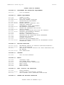
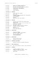
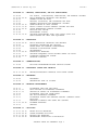


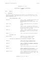
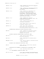
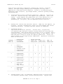


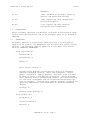


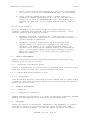

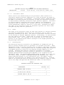


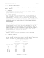


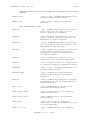
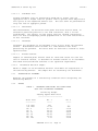


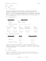


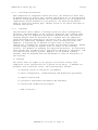
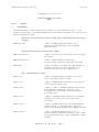


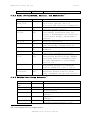

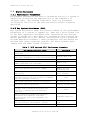


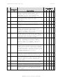
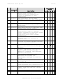
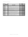
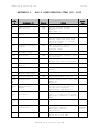

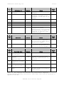


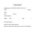


![010003E - [PROJECT.TOC] - TMG Construction Corporation](http://vs1.manualzilla.com/store/data/006000704_1-51daa2ac67e6ebfb9337b1b072f623df-150x150.png)