1
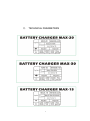
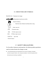
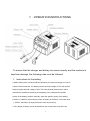
USER´S MANUAL BATTERY CHARGERS MAX -20 1 WENLIGN WANSHUN ELECTROMECHANICS MANUFACTURE CO .,LTD Add: South of Jiulong Road , Wenling Industrial Zone, Wengling City, Zhejiang Province,China Please read this User’s Manual thoroughly before using the charger. Ⅰ. PRODUCTS OVERVIEW Like all other products from SMARTER TOOLS , this item was developed on the basis of state-of-the-art, engineering and using the most reliable and modern electrical/electronic components, it is tiny, high-efficiency as well as energy-saving; the charger can used to charge for battery with either 12V or 24V and can adjust the current through changeable switch(scale or small) according to capacity of battery; the charger is designed for 12V and 24V lead –acid battery. The quality of the charger is reliable; it can be popular used in family, store etc. Auxiliary function for start-up, it can be used for charging and startingthe lead-acid batteries and batteries for motorcycles, automobiles, tractors and ships. 2 Ⅱ. TECHNICAL PARAMETERS 3 Ⅲ .INDICATIONS AND SYMBOLS EN60335-2-29: Standards for charger :Single-phase transformer-rectifier : Symbol of battery : : Read the User’s Manual carefully before using. Indoor use only IP20: Protection class MIN: DC Min output current MAX: DC Max output current FUSE T5A : Input fuse 12V/24V Switch Ⅳ. SAFETY REGULATIONS For the safety of persons and properties, the following safety regulations must be observed when the charger is used. As the flammable gas can be generated in the course of charging, the battery should be charged inside the room with good ventilation. Flames and sparks should be kept away and smoking is prohibited. 4 For the protection class is IP20, the product shall not be used outside the room, where it is the rainy and snowy. The grounding wire must be connected to the socket so that the pin for grounding inside the plug can be reliably earthed. In the course of charging, the charger should be put at a level place and should not be tilted or reversely placed. As the casing can generate heat during charging, it is prohibited to cover the vent of casing. The instructions for the battery and transportation tools should be strictly followed in the course of charging. The battery should be mounted or dismantled after the power is turned off. The maintenance work for the charger should be done by the professionals. The fuse and cable with the same specifications should be used when they need to be replaced. As sulfuric acid gas, hydrogen and oxygen, which are strongly erosive, can be generated in the course of charging, the battery should be charged inside the room with good ventilation. Flames and sparks should be kept away and smoking is prohibited. The power socket should be connected with the grounding wire so that the pin of power cord can be reliably earthed. The battery should be mounted or dismantled after the power is turned off. When electrified, the battery clamps should not be contacted with each other. The cover of battery should be opened in the course of charging. It is prohibited to connect the battery clamps reversely. (e.g., wrongly connect the red clamp of anode to the cathode of battery, or wrongly connect the black clamp of cathode to the anode of battery) It is prohibited to use the charger for the charging of non-charging batteries. The fuse with the same specifications as the original configuration should be used when they need to be replaced. Do not use other conductors to replace the fuse. In case the power cable is damaged, the damaged cable should be dismantled and replaced by professionals for maintenance. 5 Ⅴ . OPERATION INSTRUCTIONS To ensure that the charger and battery are used correctly and the machine is kept from damage, the following rules must be followed: 1.Instructions for the battery ● When battery does not have sufficient electricity, the terminal voltage of it can be normal, which means the 12V battery has the terminal voltage of 12V and the 24V battery has the terminal voltage of 24V. The main physical phenomenon, which indicates the insufficient electricity in the battery, is the changeof the specific gravity of the battery solution. Normally, when the specific gravity of the battery solution is 1.28KG/L, the electricity volume of battery is sufficient. If it is lower than 1.16KG/L, the battery is empty and won’t have any electricity. ● The voltage of battery can be deviated from the normal value only when the 6 battery is loaded or charged. When loaded, the voltage is lower than normal value of terminal voltage, whereas it is higher than normal value when the battery is being charged. If the battery is topped for some time (about 10-30 minutes) after it is loaded, and the terminal voltage is still lower than normal value, the battery may have quality defects. ● Remove the cover of the battery to see if the electrolytic solution in it is sufficient. If not, add more distilled water into it till it is sufficient so as to make it prepared for charging. As the electrolytic solution in the battery is dilute sulfuric acid and strongly erosive, it can’t contact the skin or clothes. In case the electrolytic solution has contacted the skin, the contacted area should be washed with water immediately and the contacted person should be sent to the hospital for medical treatment timely. 2.Correct charging method: 1. Connect the (red) anode of battery clamp to the anode of the battery and the corresponding terminal (12V or 24V) of the charger. Connect the (black) cathode of battery clamp to the cathode of the battery. car needs to be charged, first you should connect the charger to the terminal which is not connected with the chassis, then connect the other terminal of charger to the chassis. The connecting points must be far away from the battery and fuel tubes . 2 : Pls chosse the 12V or 24V by the switch corresponding to the battery voltage . 3. Insert the power plug and turn the power switch to “ON” position. 4. There are options of charging speed which could be carry out by “MIN” “MAX” Switch .The Ammeter will indicate the current delivered towards the battery . 7 5.The charging was done when the ammeter decreased close to “0” . 6. After the charging is finished, the power should be turned off first, and then the battery clamp should be removed from the battery. Note : ● In the course of charging, the temperature of electrolytic solution in the battery should not be more than 45 ℃. If the charging is not finished and the temperature reaches 45 ℃, the charging current should be lowered down so as to prolong the charging time and make the temperature of electrolytic solution not increase continuously until the charging is completed. ● The following phenomena may occur after charging is finished: Specific gravity of battery solution is close to 1.28KG/L; Terminal voltage of battery is increased to more than 14V (or 28V); Electrolytic solution is heavily bubbled up. Ⅵ MAINTENANCE ● Regular maintenance and repair work can ensure the machine is properly used and its condition complies with the safety requirements. ● Any improper or incorrect operation may cause the failure and damage for the machine. ● The warranty period for the machine is one year commencing from the date of purchasing. Within this time, users can take the machine with the invoice to the distributor or the designated department for repair. ● Before the maintenance work for machine is started, the operator must turn off the main power at power distribution cabinet and the power switch of the machine. ● If the transformer is heating and no current is available from the transformer due to the over current in the course of charging, it is because the over-heat protection device inside the charger is started to protect the transformer. In this case, the user should wait till the 8 transformer is cooled to resume the charging process. Ⅸ No. Specification 1 2 3 4 5 6 7 8 9 10 11 12 13 14 15 16 17 18 19 20 21 22 23 24 25 26 27 28 29 30 31 GB/T 818-2000 M4×16 GB/T848-2002 4 50A 85C17-A K10-2 KCD-25 250w/10A 5x20 WS/01-MAX-30-04 K10-2 GB/T 818-2000 M4×25 QL5010S 50A GB/T859-87 4 GB/T6170-2000 M4 GB/T818 M4×10 188×25×3 140X25MM WS/01-MAX-30-03 ST4.8×13 WS/01-MAX-30-02 GB/T6170-2000 M5 GB/T859-87 5 GB/T848-2002 5 GB/T 818-2000 M5×16 GB9074.13-88 M4×12 WS/01-MAX-30-01 10A 3X1.5MMX2.4M KCD-25 LIST OF PARTS Item Cross rexxessed pan head tapping screw cushion Plastic front panel fixed connetion ammeter output fuse power switch Input fuse Front panel switch Cross rexxessed pan head tapping screw rectifier Spring Cushion Hex nut Cross rexxessed pan head tapping screw belt Belt buckle Top cover Cross rexxessed pan head screw Back panel Transformer Hex nut Spring gasket Cushion Cross reccessed pan head screw Plain washer assemblies Cross recessed hexagon bolt base Accumulator lamp Power cable ON/OFF switch 9 QTY 2 4 1 2 1 1 1 1 10 1 2 2 3 1 2 1 10 1 1 4 4 4 4 4 2 1 2 1 10