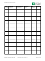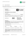
1
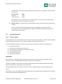
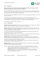
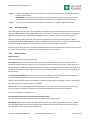
ICM VERTICAL Fall Arrest System ICM VERTICAL Fall Arrest System User Manual Part 2: System Installation For instructions on daily use with the ICM Fall Arrester, see User Manual Part 1 for the ICM VERTICAL Fall Arrest System. Important information on the ICM VERTICAL Fall Arrest System The ICM VERTICAL Fall Arrest System consists of a guided type fall arrester and a rigid anchor line. The guided type fall arrester must be the ICM Fall Arrester or the Protecta Cabloc AC350/4 fall arrester. The rigid anchor line must be an 8 mm steel wire rope. All components of the ICM VERTICAL Fall Arrest System, except the Protecta Cabloc AC350/4 fall arrester, must be supplied by ICM-ArSiMa A/S. For the Protecta Cabloc AC350/4 fall arrester consult the manual supplied with the Protecta Cabloc AC350/4 fall arrester. If a Protecta Cabloc AC350/4 fall arrester is used with the ICM VERTICAL Fall Arrest System, make sure the fall arrester has been inspected by a competent person within the last 12 months. Only when the complete fall arrest system, incl. guided type fall arrester, is supplied by ICM we have full product responsibility. For avoidance of any doubt, if the guided type fall arrester is not supplied by us then any claims or liability matters, including but not limited to product responsibility, regarding this item, shall be addressed directly to the supplier of this item. This manual must be made available to the user and installer in the official languages of the country of destination. It must be read and understood by both the user and installer before using and installing the system. Follow the guidelines for PPE related to the use and installation of the system. Be aware that any alterations of components, misuse of the system and related PPE, or not following the instructions given by the manufacturer is not allowed. Questions regarding installation, use, maintenance, or choice of product to suit the application can be addressed to ICM-ArSiMa A/S. Copyright 2014 ICM-ArSiMa A/S 3 December 2014, version 11 Page 1 of 20 ICM VERTICAL Fall Arrest System CE type approval of the ICM VERTICAL Fall Arrest System The ICM VERTICAL Fall Arrest System is designed and tested to standards EN 353-1:2002, prEN 353-1:2008 and RfU CNB/P/11.073 according to PPE Directive 89/686/EEC §10 EC type examination at notified body: FORCE-Certification A/S Park Allé 345 2605 Brøndby Denmark Notified body No. 0200. The control test according to PPE Directive 89/686/EEC§11A is done at above-mentioned notified body. This document is part of the CE approval for the complete system. Additional testing The ICM Vertical fall arrest system has also been submitted to “Fall Back testing using an anthropometric dummy” by TUV NEL Scotland, November 9th 2007, certificate no. PPE700000 MTHU. Copyright 2014 ICM-ArSiMa A/S 3 December 2014, version 11 Page 2 of 20 ICM VERTICAL Fall Arrest System Table of Contents User Manual Part 1: Daily use User Manual Part 2: System Installation 3. 4. 5. SYSTEM INSTALLATION .............................................................................................................................. 4 3.1. Applications ....................................................................................................................................... 4 3.2. System components .......................................................................................................................... 5 3.3. Load requirements for anchors ......................................................................................................... 8 3.4. Installing the system .......................................................................................................................... 9 INSPECTION ............................................................................................................................................. 13 4.1. When to inspect .............................................................................................................................. 13 4.2. How to inspect the ICM VERTICAL Fall Arrest System installation .................................................. 13 4.3. How to inspect the ICM Fall Arrester .............................................................................................. 14 4.4. If the system does not pass inspection ........................................................................................... 14 4.5. Maintenance, service, and storage ................................................................................................. 15 4.6. Optional tamper proofing................................................................................................................ 15 4.7. System data storage ........................................................................................................................ 16 APPENDIX A ............................................................................................................................................. 19 Copyright 2014 ICM-ArSiMa A/S 3 December 2014, version 11 Page 3 of 20 ICM VERTICAL Fall Arrest System 3. SYSTEM INSTALLATION 3.1. Applications The ICM VERTICAL Fall Arrest System is to be installed on fixed, vertical ladders or similar vertical climbing surfaces that are part of the structure. The system is installed to protect users connected to the system from falling while climbing. The system is only to be installed by a competent person. See back page for information on being competent. 3.1.1. Limitations Do not install the ICM VERTICAL Fall Arrest System on portable ladders or movable surfaces. Consider the following limitations before installing or using the ICM VERTICAL Fall Arrest System: A. Anchors: The anchorage points to which the system is installed must be able to withstand the loads applied by the system in the event of a fall. See section 3.3. B. System capacity: The ICM VERTICAL Fall Arrest System fulfils the requirements stated in EN 353-1:2002 and prEN 353-1:2008 with a user weight of 40 – 136 kg. The ICM VERTICAL Fall Arrest System fulfils the requirements stated in RfU CNB/P/11.073 with a user weight of 40 – 136 kg. It is recommended by the manufacturer that the user does not weigh more than 136 kg incl. tools and clothing. The system is approved for the use of up to three persons on the system at one time. See section 3.3 for system requirements and Appendix A for manufacturer’s recommendations. IMPORTANT: The installer must indicate on the system identity label how many users are allowed on the system at one time. C. Environmental hazards: Be aware of environmental hazards, which can damage the system or injure the user. The hazards could in example be welding, strong heat, the use of movable or metal cutting tools, acids and chemicals, explosive or toxic gasses, solutions containing salt, electricity, oil, dust, grease, and sharp objects and edges. The system is to be used in the temperature range of -30 – +45°C. When working at low temperatures, always remember before use to remove ice built up on the system or on the fall arrester, since the system otherwise could fail to function as intended. D. Component compatibility: The ICM VERTICAL Fall Arrest System shall be installed and used as described in this manual. Do not leave out or change any components in the system. Only the ICM Fall Arrester supplied by ICM-ArSiMa A/S, or alternatively the Protecta Cabloc AC350/4 fall arrester, can be used with the ICM VERTICAL Fall Arrest System. Only use the system in combination with a full body harness approved to EN 361 or EN 361 + EN 358. The harness must have a front attachment point for ladder climbing. E. Training: As any other PPE, the ICM VERTICAL Fall Arrest System is only to be used by people who have received proper instruction and training in how to use the system. Copyright 2014 ICM-ArSiMa A/S 3 December 2014, version 11 Page 4 of 20 ICM VERTICAL Fall Arrest System 3.1.2. EN standards The ICM VERTICAL Fall Arrest System is designed to fulfil the requirements in the following European standards: EN353-1:2002, prEN353-1:2008, EN364 and EN365. 3.2. System components When using stainless steel wire rope Item no. ICM Fall Arrester 6804500 or Protecta Cabloc AC350/4 fall arrester n/a Shackle 0.6 ton stainless steel AISI 316 6803011 or Shackle1.5 ton, galvanized steel 6803000 or Shackle 2 ton, galvanized steel 6803005 8 mm wire rope, 7x19, stainless steel 6804315 Swaged eye with thimble on 8 mm stainless steel wire rope 6804351 Thimble 8 mm, stainless steel 6804318 Rigging screw, stainless steel 6804330 Wire rope clip 8 mm, stainless steel 6804321 Simplex wire clip 8 mm, stainless steel 6804390 Wire rope guide “537122/537123” 6804503 Wire rope guide “AC320” 6804502 Wire rope guide “FsNw styrnyl” 6804504 When using galvanized steel wire rope Item no. ICM Fall Arrester 6804500 Shackle1.5 ton, galvanized steel 6803000 or Shackle 2 ton, galvanized steel 6803005 8 mm wire rope, 7x19, galvanized steel 6804335 Swaged eye with thimble on 8 mm galvanized steel wire rope 6804363 Thimble 8 mm, galvanized steel 6804354 Rigging screw, stainless steel 6804330 Wire rope clip 8 mm, galvanized steel 6804360 Wire rope guide “537122/537123” 6804503 Wire rope guide “AC320” 6804502 Wire rope guide “FsNw styrnyl” 6804504 Do not leave out or change any components in the system. Copyright 2014 ICM-ArSiMa A/S 3 December 2014, version 11 Page 5 of 20 ICM VERTICAL Fall Arrest System 3.2.1. Requirements for connectors Use only the shackle 6803000, 6803005 or 6803011 to connect the wire rope to the top anchor. The shackles are capable of supporting a minimum of 36 kN. Only the 6803011 is for offshore use. Note: See section 3.4.3 step 2. Use only the EN 362 approved 25 kN karabiner supplied with the ICM Fall Arrester or the Protecta Cabloc AC350/4 fall arrester to connect to the harness. 6804500 ICM Fall Arrester Stainless steel cable grab with polyester energy absorber. Breaking strength >15 kN. Karabiner with twistlock (AJ 514). Galvanized steel. Breaking strength >16kN. Thin wire must be present for permanent connection between cable grab and karabiner on energy absorber. AJ514 karabiner locked to the fall arrester For use with Ø 8 mm, 7 x 19, stainless steel wire rope as specified for the ICM VERTICAL Fall Arrest System. Energy absorber AJ514 karabiner, to be connected to front D-ring of the EN361 harness Alternatively: Protecta Cabloc AC350/4 fall arrester 6803000 Shackle 1.5 ton Shackle with locking pin. Galvanized steel. Breaking strength >36 kN 6803005 Shackle 2 ton Shackle with locking pin. Galvanized steel. Breaking strength >36 kN 6803000 6803005 6803011 offshore 6803011 Shackle 0.6 ton Shackle with locking pin. Stainless steel AISI 316 Breaking strength ≥36 kN 6804315 Stainless steel wire rope Stainless steel wire rope, diameter 8 mm, construction 7 x 19. Weight approx. 250 g/m. Breaking strength >36 kN. Copyright 2014 ICM-ArSiMa A/S 3 December 2014, version 11 Page 6 of 20 ICM VERTICAL Fall Arrest System 6804351 Eye on stainless steel wire Wire rope eye termination for connection to the top anchor. Stainless steel thimble and copper ferrule. The system identity number is stamped in. Optional stamping of SWL value. 6804335 Galvanized steel wire rope Galvanized steel wire rope, diameter 8 mm, construction 7 x 19. Weight approx. 250 g/m. Breaking strength >36 kN. 6804363 Eye on galvanized steel wire Wire rope eye termination for connection to the top anchor. Galvanized steel thimble and aluminium ferrule. The system identity number is stamped in. Optional stamping of SWL value. 6804318 Thimble, stainless steel Stainless steel thimble for diameter 8 mm stainless steel wire rope. 6804354 Thimble, galvanized steel Galvanized steel thimble for diameter 8 mm galvanized steel wire rope 6804330 Rigging screw, stainless Stainless steel, with fork shape at each end. 6804332 Rigging screw, stainless, with tension indicator Stainless steel, with fork shape at each end and indicator for correct wire rope tension (0.8 kN). Optional, replaces 6804330. Copyright 2014 ICM-ArSiMa A/S 3 December 2014, version 11 Page 7 of 20 ICM VERTICAL Fall Arrest System 6804321 Wire rope clip, stainless For 8 mm stainless steel wire rope. 6804360 Wire rope clip, galvanized For 8 mm galvanized steel wire rope. 6804390 Simplex wire clip, stainless For 8 mm stainless steel wire rope. Three clips are required to terminate the wire rope at the bottom anchor. All clips are available with locking nuts. 6804503 Wire rope guide 537122+537123 Stainless steel body to fit the rung, and plastic part to support the wire rope. Rung dimension maximum 30x30 mm. Wire rope diameter maximum 8 mm. 6804502 Wire rope guide AC320 Stainless steel body and rubber part to support the wire rope. Rung dimensions minimum 16x16 mm, maximum 42x42 mm. 410.099 Wire rope guide FsNw styrnyl Stainless steel body and nylon part to support the wire rope. To be mounted in pairs either on corner legs or on ladder legs. The wire rope has to be moved both outwards and then inwards in order for the cable grab to pass. The brackets for mounting (U-bolts) are fitted for the dimensions it must be fitted on. 3.3. Load requirements for anchors The anchors and climbing structure to which the ICM VERTICAL Fall Arrest System is installed must be capable of supporting the loads imposed by the system. A. Top anchor: To be designed by the user so it can withstand the required load. The installer of the system must be able to document that the anchor has been tested or calculated to withstand the required load in a static test for a period of minimum 3 minutes. Copyright 2014 ICM-ArSiMa A/S 3 December 2014, version 11 Page 8 of 20 ICM VERTICAL Fall Arrest System Required load on top anchor depending on how many persons are allowed to use the system at one time: No. of persons: 1 person 2 and 3 persons Load: 15 kN 20 kN See Appendix A for the manufacturer’s recommendations for the top anchor when having two or three persons on the system at one time. B. Bottom anchor: The bottom anchor must be able to support a load of 2 kN in the direction of loading. This is not relevant if the bottom end of the wire is hanging free and the bottom end termination of the wire is equipped with a weight of more than 10 kg allowing the wire to hang straight and tensioned. 3.4. 3.4.1. Installing the system Before starting The ICM VERTICAL Fall Arrest System is to be installed on fixed, vertical ladders or similar vertical climbing surfaces that are part of the structure. When installed, the system must be vertical. Plan the installation ahead to save time and increase safety. Install the system in the following way: 1) 2) 3) 4) 5) 6) Install the top anchor Connect the wire rope to the top anchor Install the wire rope guides and insert the wire rope Install the bottom anchor Tension the wire rope Inspect the installation IMPORTANT: Be careful when installing the system. Always use a fall arrest system during the installation. Do not connect yourself to the ICM VERTICAL Fall Arrest System if it is incomplete. During the installation the installer must wear CE approved personal protective equipment like safety helmet, safety glasses, safety gloves, and safety shoes. The ICM VERTICAL Fall Arrest System is not to be used for anything else but a vertical climbing safety system. The system is only to be installed and used by people who are medically fit and in good physical condition, and trained to climb the required distances. Copyright 2014 ICM-ArSiMa A/S 3 December 2014, version 11 Page 9 of 20 ICM VERTICAL Fall Arrest System 3.4.2. Top anchor Always have the top anchor and ladder inspected by a qualified engineer before installing in order to determine if the load requirements for the system are fulfilled. The position of the top anchor shall allow the user safe access when connecting or disconnecting from the system. The top anchor must be positioned in the centre of the ladder rungs to ease of climbing, but it may be positioned anywhere within the width of the ladder rung. When using wire rope guide 6804503 the centre of the wire rope should be positioned approx. 75 mm from the front of the rungs. When using wire rope guide 6804502 the length of the wire rope guide is adjustable, however, it is recommended the centre of the wire rope is positioned approx. 10 cm from the ladder rungs. It is allowed to shorten the wire rope guide if the thread bar is in conflict with the construction behind. For load requirements to top anchor, see section 3.3. 3.4.3. The wire rope 6804315 Stainless steel wire rope: The wire rope is 8 mm thick, construction 7x19, stainless steel, breaking strength >36 kN. The wire rope must always be supplied by ICM-ArSiMa A/S. 6804351 Swaged eye for stainless steel wire rope: For the ICM VERTICAL Fall Arrest System the wire rope must have a swaged eye with stainless steel thimble and a copper ferrule swaged to EN 13411-3 2004. The system identity number is stamped in the ferrule. It is optional to have the SWL value (Safe Working Load) stamped in the ferrule as well. The SWL for the wire rope with eye is approx. 0.7 ton (at safety factor 5). 6804335 Galvanized steel wire rope: The wire is 8 mm thick, construction 7x19, galvanized steel, breaking strength >36 kN. The wire rope must always be supplied by ICM-ArSiMa A/S. 6804363 Swaged eye for galvanized steel wire rope: For the ICM VERTICAL Fall Arrest System the wire rope must have a swaged eye with galvanized steel thimble and an aluminium ferrule swaged to EN 134113 2004. The system identity number is stamped in the ferrule. It is optional to have the SWL value (Safe Working Load) stamped in the ferrule as well. The SWL for the wire rope with eye is approx. 0.8 ton (at safety factor 5). 6803000 Shackle: The shackle is to connect the swaged eye of the wire rope with the top anchor. Always remember to lock the shackle with the locking pin. Step 1. Roll out the wire rope on the ground and inspect it for shipping damages. If there are any damages to the wire rope do not install it but have it exchanged or inspected by a competent person. See back page for information on being competent. IMPORTANT: Always wear correct personal protective equipment when handling the wire rope, since the wire rope can unintended cause injuries. Use i.e. safety glasses and safety gloves when handling the wire rope. Copyright 2014 ICM-ArSiMa A/S 3 December 2014, version 11 Page 10 of 20 ICM VERTICAL Fall Arrest System Step 2. Connect the swaged eye at the end of the wire rope with the top anchor by using the shackle. Lock the shackle safely. IMPORTANT: The shackle may be left out of the ICM VERTICAL Fall Arrest System if the top anchor itself is suitable for direct and safe connection to the swaged eye of the wire rope. Step 3. Lower the wire rope safely underneath the top anchor so it hangs alongside the ladder. 3.4.4. Wire rope guides Wire rope guides keep the wire rope in position and prevent the wire rope from moving from side to side during climbing and from hitting against the ladder or structure. In windy conditions the wire rope guides shall also prevent the wire rope from moving side wards and thereby reduce noise from the system. Wire rope guides shall be mounted along the wire rope between the top and bottom anchor. When installed indoor the distance between the wire rope guides shall not exceed 15 m. When installed outdoor the distance shall not exceed 9 m. For offshore use we recommend a shorter distance. The distance between the wire rope guides shall be shorter if there is a chance that the wire rope can come in contact with the ladder or structure (to prevent abrasion on the wire rope). 3.4.5. Bottom anchor Bottom anchor: Two types of bottom anchors are allowed: For temporary use: A counter weight of minimum 10 kg, which allows the wire to hang free in the air, straight and tensioned. The weight is to be at the bottom end termination of the wire. It can either be an applied weight or sufficiently rolled up wire. Even if the wire is hanging free at the bottom end, and is not connected to the construction or ground, then the wire shall be placed correctly in every wire rope guide on the system. For permanent installation: A bottom anchor connection, which is part of the construction. It fulfils the required load for the bottom anchor, and it creates a true rigid wire system. Always have the bottom anchor inspected by a qualified engineer before installing in order to determine if the load requirements for the system are fulfilled. The bottom anchor shall be positioned to allow the user safe access when connecting or disconnecting from the system. The bottom anchor must be positioned vertically in-line with the top anchor. For load requirements, see section 3.3. Connecting the wire rope to the permanent bottom anchor: The wire rope is to be connected to the bottom anchor via the rigging screw. IMPORTANT: Make sure the wire rope is placed correctly in every wire rope guide on the system. Make sure the angle between the top and bottom anchor will not allow the wire rope to move away from the wire rope guides once the wire rope is tightened. Copyright 2014 ICM-ArSiMa A/S 3 December 2014, version 11 Page 11 of 20 ICM VERTICAL Fall Arrest System Proceed as following: 3.4.6. Connect the rigging screw to the bottom anchor. Loosen the nuts and turn the rigging screw into max length. Run the wire rope through the free end of the rigging screw. Place thimble between the wire rope and the rigging screw in order to protect the wire rope. Cut the free end of the wire rope allowing 40 cm to run through the rigging screw and back towards itself. Loosely clamp the wire rope clips around the wire rope. Slide the free end of the wire rope through the wire rope clips. Tighten the wire rope by hand until there is no slack, and lock it in its position with the wire rope clips. Three clips are required, and they shall be place with a distance of approx. 10 cm. The first clip shall be placed so close to the rigging screw that the thimble is unable to move out of place. Note: When mounting the wire clip the “saddle” of the clip shall press on the wire going downwards. The U-bolt part of the clip shall bite on the free end of the wire going upwards. In outdoor windy conditions use the Simplex wire clip as the lowest of the three clips. Cut of excess wire rope 5 cm from the top wire rope clip, and protect the free end with tape. Tensioning the wire rope when using a permanent bottom anchor Tighten the rigging screw until the tension in the wire rope is 0.8 kN. To determine correct tension: A) Use a wire rope tension meter. b) Use the optional rigging screw with tension indicator. Lock the rigging screw in its position by tightening the nuts If the wire rope remains slack and the rigging screw is at its minimum, then bring the rigging screw back to its maximum, loosen the wire rope clips, and tighten the wire rope more by hand Then retighten the rigging screw once again and lock it in its position IMPORTANT: For systems installed in areas with large temperature ranges or strong winds it is likely they will require to be re-tensioned periodically. The longer the system, the more likely it is to require periodically re-tensioning. 3.4.7. Final inspection and system identification A. Install the system identity label onto the ladder or as close to the entrance point of the system as possible. The installer shall put the following data in permanent writing on the label: A unique system identity number given by the manufacturer or created by the installer, the date of installation, name of the installer, and number of users allowed on the system at one time. Record the same data on the system registration card. B. After installation conduct a final inspection of the system as follows: Make sure all connectors and fasteners are properly closed and tightened. Make sure the wire rope is not in conflict with the ladder or structure at any point. Copyright 2014 ICM-ArSiMa A/S 3 December 2014, version 11 Page 12 of 20 ICM VERTICAL Fall Arrest System Make sure the wire rope is properly placed in all wire rope guides. Make sure the wire rope is sufficiently tightened so there is no slack in the wire rope. Make sure the system identity label is in place at the entrance of the system and the system data are correctly written on the label and on the registration card. 4. INSPECTION 4.1. When to inspect Before each use: Make a visual and operating inspection of the ICM Fall Arrester before use. Inspect the condition of the cable grab and energy absorber, mechanical function of the locking lever and karabiners. Inspect for any kind of deformation. Inspect the condition of the installed system in general. Inspect the wire rope for broken strands. Inspect the ladder or ladder structure in regards to safe climbing. Formal inspection: All components that are part of the ICM VERTICAL Fall Arrest System together with the ladder or ladder structure must be inspected at least every 12 month by a competent person. See back page for information on being competent. The outcome of the formal inspection must be logged on the System Identity Label and the registration cards for the system and the ICM Fall Arrester. After a fall: In case the ICM VERTICAL Fall Arrest System arrests a fall it shall be replaced. 4.2. How to inspect the ICM VERTICAL Fall Arrest System installation Inspect top and bottom anchors for deformation, corrosion, or any kind of damage. Check for anything that could affect the strength of the anchor or the function and quality of the system. Inspect the wire rope guides. Make sure they are correctly mounted and maintain their grip on the wire rope. Check for tear, deformation, and loose fasteners. Retighten the wire rope guide if required. Inspect the wire rope for damage. Check for worn or broken strands. Inspect for signs of abrasion from the ladder or structure. The wire rope must not contact the ladder or structure. Replace damaged wire rope if necessary. Check the wire rope for correct tension and re-tighten if necessary. Inspect the swaged eye of the wire rope and the ferrule. Ensure the ferrule shows no sign of corrosion, deformation, or slip from its original position at the time of manufacture. Replace damaged wire rope if necessary. Inspect the shackle connecting the wire rope to the top anchor. Check for deformation, corrosion, or any kind of damage, which could affect the strength of the shackle. The locking pin must be in place; if not, insert a new locking pin. Inspect the rigging screw, thimble, and wire rope clips connecting the wire rope to the bottom anchor. Check for deformation, corrosion, or any kind of damage, which could affect the strength of the components. The locking pins must be in place at both ends of the rigging screw. Retighten the nuts on the wire rope clips if necessary. Copyright 2014 ICM-ArSiMa A/S 3 December 2014, version 11 Page 13 of 20 ICM VERTICAL Fall Arrest System 4.3. 4.4. Inspect the ladder structure for damage, corrosion or deterioration that could affect the strength of the ladder. Inspect the system identity label. Make sure the label is located at the entrance point of the system, and that all data is filled in. How to inspect the ICM Fall Arrester Inspect the steel cable grab and locking lever for deformation, cracks, and corrosion. All pins holding the parts together must be present and in good condition. The lever and wire rope channel must be clean, smooth and operated without unintended resistance. Inspect the steel cable grab for wear on the inside of the wire rope channels, where the wire rope passes through. Inspect labels and markings put on the equipment by the manufacturer. All labels and markings must be present and completely legible. Inspect the karabiners. Check for deformation, corrosion, cracks and damages. Inspect that the double function twistlock system operates correctly. From an open position, the karabiner must lock automatically without any assistance. Check that no karabiners have been substituted. Inspect the thin wire rope permanently connecting the energy absorber to the cable grab of the fall arrester. The thin wire rope shall prevent the lanyard from being separated from the cable grab of the fall arrester. Inspect the locking system of the cable grab. With the karabiner in place in the cable grab, then it may not be possible either to insert or remove the wire rope. Inspect the energy absorber. An undamaged heat-shrink clear sleeve made by the manufacturer must protect it. No webbing may be pulled out in either end. Due to natural degradation of the materials, the end of life of the energy absorber is reached after 7 years from the manufacturing date or 5 years after taking into service; whatever comes first. The energy absorber can only be replaced by the manufacturer. The date of manufacture must be readable through the clear sleeve; if not, the energy absorber must be replaced. Check the function of the fall arrester by putting it on the wire rope and slightly pulling the lanyard downwards. When pulled the fall arrester shall grab on the wire rope and keep its position. If the system does not pass inspection If any component, which is part of the ICM VERTICAL Fall Arrest System, in any way fails to fulfil the guidelines set in section 4.2 and 4.3, then the complete system must be withdrawn from use until it has been formally inspected by a competent person. See back page for information on being a competent person. Copyright 2014 ICM-ArSiMa A/S 3 December 2014, version 11 Page 14 of 20 ICM VERTICAL Fall Arrest System 4.5. Maintenance, service, and storage The ICM VERTICAL Fall Arrest System requires no scheduled maintenance, however, the system shall be inspected at least once a year according to the guidelines in section 4.0. All components part of the ICM VERTICAL Fall Arrest System are made of galvanized steel, stainless steel, polyester or rubber. Contact ICM-ArSiMa A/S for further details. If the wire rope requires cleaning contact the installer for recommendations. Do not use any kind of chemical which could damage the wire rope. It is recommended to clean the ICM Fall Arrester on regular basis with a dry cloth. If required, metal parts may be cleaned using a commercial parts-cleaning solution and thereafter washed in lukewarm, soapy water. Moving parts may be applied light machine oil. Do not apply oil to any parts in contact with the wire rope. Store the fall arrester and other components in a ventilated room at normal room temperature. The fall arrester may not be permanently exposed to sunlight or corrosive environment. Remember to check for the latest date of inspection after prolonged storage. Always remember to store the equipment and system registration cards in a safe area known to the user. A competent person must complete additional maintenance and servicing procedures. See back page for information on being a competent person. 4.6. Optional tamper proofing Under certain circumstances, e.g. if the system is installed in a remote place, then it may be relevant to indicate to the user, whether someone could have tampered with the installed system. An easy way to indicate tampering with the system is to place a heat-shrink clear sleeve over the connection between wire rope and rigging screw to show physical evidence of any tampering with the system. Other methods of indication are available – ask the installer. The installer should make this tamper proofing. It is recommended but not mandatory. Copyright 2014 ICM-ArSiMa A/S 3 December 2014, version 11 Page 15 of 20 ICM VERTICAL Fall Arrest System 4.7. System data storage The installer must keep a record of system identity number, location, and date of installation relating to a particular system. The installer must fill in the System identity label to complete the installation. 4.7.1. Registration card for the system installation Name of installer: Date of installation: System identity number: Date of Items to be inspection addressed Copyright 2014 ICM-ArSiMa A/S Recommendations on what to do Performed service 3 December 2014, version 11 Next inspection Approved by Page 16 of 20 ICM VERTICAL Fall Arrest System Date of Items to be inspection addressed Copyright 2014 ICM-ArSiMa A/S Recommendations on what to do Performed service 3 December 2014, version 11 Next inspection Approved by Page 17 of 20 ICM VERTICAL Fall Arrest System 4.7.2. System identity label Must be located at the entrance point of the system. For identification purposes the installer must create a unique individual system identity number. Copyright 2014 ICM-ArSiMa A/S 3 December 2014, version 11 Page 18 of 20 ICM VERTICAL Fall Arrest System 5. APPENDIX A Manufacturer recommendation when having two or three persons on the system at one time: It is allowed to have one, two or three persons on the system at one time, if the following requirements are met: Requirements to top anchor The top anchor must be able to withstand a static load of: 15 kN for one person or 20 kN for two or three persons on the system at one time. The installer of the system must be able to document that the top anchor has been calculated by a qualified engineer or tested to withstand the required loads for a period of minimum 3 minutes. Requirements for other components Do not leave out or change any components in the ICM VERTICAL Fall Arrest System. The components are already designed for having two or three persons on the system at one time. Wire rope with eye termination: Tested at Force Certification A/S, notified body no. 0200, can withstand a load of more than 36 kN. Shackle: 6803000 and 6803005 have a WLL (Work Load Limit) of respectively 1.5 and 2 tons with a safety factor 6 against breaking, which equals to a 9 and 12 tons breaking strength (90 and 120 kN). 6803011 has a WLL of 0.6 tons with safety factor 6, which equals to a 3.6 tons breaking strength (36 kN). When climbing For the first two metres the user may not be protected against hitting the ground, extra care should be taken when ascending or descending. For those systems which permit more than one user there should be a minimum distance of 3 m between the feet of the upper person and the head of the lower person. When working at heights, always make sure that carried items are secured from dropping on climbers below. Copyright 2014 ICM-ArSiMa A/S 3 December 2014, version 11 Page 19 of 20 ICM VERTICAL Fall Arrest System Warranty: Provided the component is supplied by ICM-ArSiMa A/S, either directly or through a retailer, then we offer a warranty of one year from the date of installation for all components of the ICM VERTICAL Fall Arrest System, provided this period shall not exceed 18 months from the date of purchase from ICM-ArSiMa A/S. The warranty does not cover component damages caused by vandalism, shipping, or other types of damage not controllable by ICM-ArSiMa A/S. The warranty only covers ICM VERTICAL Fall Arrest Systems that are installed, inspected, and serviced by competent personal. A competent person: By being competent in installing, inspecting, and servicing the ICM VERTICAL Fall Arrest System we as the manufacturer expect the following: A competent person has received training by the manufacturer or knows from experience how to inspect, service, and use a wire system approved to EN 353-1. A competent person has read and fully understood the user manual Part 1 and 2, and he/she is fully aware of the proper use, limitations, and possible misuse of the system. If required by the manufacturer or the customer, competent personal must be able to document their qualifications. If you doubt whether you or your employees are competent to install, inspect, and service the ICM VERTICAL Fall Arrest System, then contact ICM-ArSiMa A/S for further guidance. ICM-ArSiMa A/S Hammervej 1-3 2970 Hørsholm Denmark Tel: +45 45 86 62 22 Fax: +45 45 76 57 27 Email: [email protected] Copyright 2014 ICM-ArSiMa A/S 3 December 2014, version 11 Page 20 of 20