1
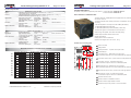
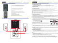
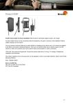
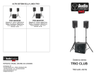
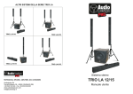
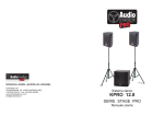
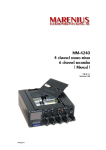
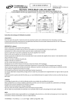
PROFESSIONAL SPEAKERS, AMPLIFIERS AND ACCESSORIES
Audiodesign Srl
Via dell’industria, 28 - 42025 CAVRIAGO (RE)
+39 0522 941444 - Fax +39 0522 942363
www.audiodesign-pro.com
[email protected]
Full Range Sound System
KPRO 15.10
STAGE PRO series
User Manual
Portable Full Range Sound System KPRO 15.10
Portable Full Range Sound System KPRO 15.10
Stage Pro Series
Introduction
Thank you for purchasing an AudioDesign KPRO Active Sound system.
KPRO series is designed to provide an high and powerful sound quality in a compact size.
The main features are:
* Active subwoofer cabinet with additional amplifiers for the passive satellites.
* High sensitivity passive satellites.
* High and precise acoustic quality also with high power.
* Portability: the system is easy fit and portable by one person.
The final result is a full, detailed and powerful sound.
Application
The KPRO systems are a professional solution for every DJ or Live events where high pressure and extreme
sound quality is required.
Precautions:
Caution: When using any electric product , precautions should always be taken, including the following:
1) Read carefully all instructions before using the product.
2) To reduce the risk, strict supervision is necessary when the product is used near children.
3) Don't use the product near to water sources like sinks, kitchens, wet floors, pools,
or similar or when raining.
4) In case hearing losses or buzzing occur, please contact a doctor.
5) This products should be located so that its position does not interfere or reduce its proper ventilation.
6) This product should be site away from heat sources such as radiators or any other product that
generate heat.
7) This product should be connected to a power supply line only of the type described on the operating
instructions. Check always the status of the power cable.
8) In case you need to replace the fuse, unplug power supply before replacement. The fuse is located
over the power socket and needs to be replaced with a fuse of same type and value. If the fuse blows again,
please contact our service. DON'T replace it a second time with a higher value fuse.
9) Unplug power supply when left unused for a long period of time. Don't draw the cable but pull out the
plug.
10) Make sure that power switch can always be easily reached.
11) The product needs to be inspected by authorized or qualified personnel in case:
A- The power cable or plug are damaged
B- Objects or liquids fall inside the product
C- The product has been exposed to rain
D- The product doesn't appear to operate normally or exhibits a marked change in performance.
E- The product has fallen and been damaged.
12) DON'T operate on the product, except indications on the user's manual . Please refer to authorized
and qualified personnel for any other operation.
13) Caution: Don't place objects on the product's power cable or place it in a position where it could be
damaged or cause interferences. Improper installation could cause fire risk and/or personal injury.
Service
All Audio Design PRO products have been inspected and tested before leaving the factory and , if properly
used, they will work for many years. However, in case of any problem, please proceed in the following way:
Contact your dealer and inform about the defect you found
In case it won't be possible to solve the problem with the dealer, the product needs to be returned, preferably
in its original packaging or in a proper packing to protect it during the transport. Purchase documents must
be produced too.
Your dealer will arrange the shipment to our service centre.
Conformity:
Audiodesign Pro products comply with presently existing directives and standards.
-2-
Stage Pro Series
NOTES
PRODUCT WARRANTY
For the warranty validation please fill this form and send it to AudioDesign within 10 days from the purchase date.
AUDIODESIGN srl
Via dell’Industria, 28
Corte Tegge
42025 Cavriago (RE)
ITALIA
Product details
Article
Series No..
Dealer
City
Purchase date
Purchase price
Buyer details
Full name
Age
Occupation
Full adress
e-mail
AUDIODESIGN guarantees the confidentiality of the data provided with this form
-7-
Portable Full Range Sound System KPRO 15.10
Technical Specification
The KPRO 15.10 system is composed by three elements: 1 Active Subwoofer STAGE PRO W15 and
2 Passive Satellites STAGE PRO 10
OUTPUT
LINE OUT PARALLEL: 6.3 Stereo Jack Socket (Sleeve = Ground; Pin = +; Ring = -)
SATELLITE OUTPUT: Speakon NL4 (pin 1+ = +, pin 1- = -)
AMPLIFIERS
Subwoofer Power output:
Satellite Power output:
Sub PB electronic crossover:
Subwoofer:
Frequency range:
SPL Max:
300 W RMS
2x180 W RMS
Frequency
1 x 15”
20 ÷ 120 Hz
123 dB
Subwoofer weight:
Dimensions (WxLxH) cm:
43,5 kg
58,5 x 48,5 x 55
SPEAKER
WEIGHT AND SIZE
INPUT
SPEAKERS
MAIN FEATURES
WEIGHT AND SIZE
(600 W Max)
(2x360 W Max)
100 Hz
(380 mm)
(± 3 dB)
Stage Pro Series
SYSTEM COMPONENTS
SUBWOOFER STAGE PRO W15
LINE IN: 6.3 Sereo Jack Socket (Sleeve = Ground; Pin = +; Ring = -)
INPUT: Balanced and Unbalanced
INPUT
Full Range Sound System KPRO 15.10
Stage Pro Series
Active Subwoofer STAGE PRO W15
At 4 Ohm
The active subwoofer STAGE PRO W15 is equipped with a 15" (380 mm) woofer
with 100 mm voice coil.
Voice coil 100 mm
The cabinet integrate all the necessary electronics for amplification and system
processing :
3 AB class amplifiers for a total power of 600 W RMS (1060 W Max)
1 x 300 W RMS (600 W Max) Subwoofer
2 x 180 W RMS (360 W Max) Passive Satellites ( 4 Ohm load)
SATELLITE STAGE PRO 10
SATELLITES INPUT:
Speakon NL4 (pin 1+ = +, pin 1- = -)
(250 mm)
50 mm vented voice coil
1 x 10”
High Sensitivity Woofer:
Compression Horn Tweeter: Voice coil 45 mm
TOTAL IMPEDANCE:
4 Ohm
(600 W Max)
300 W RMS
TOTAL POWER:
127 dB
SPL Max:
70 ÷ 20000 Hz (± 3 dB)
Frequency range:
18 dB/oct
Passive
8000 Hz
Tweeter Crossover:
13 kg
Satellite Weight:
32 x 30 x 46
Dimensions (WxLxH) cm:
The subwoofer signal is Low Pass filteres at 100 Hz 12 db/oct.
Cabinet in high density MDF, anti-scratch embossed painting
Pratical transport handles hollowed into the wood
Integral rigid metal grill
Housing hole for ø 35 mm stand tubes
Dimension and Weight: 58,5 x 48,5 x 55 cm; 43 kg.
Control and connecting plate
7 5 6 4 9 8 10
LEFT
1 Electric net socket
2 Voltage selector
RIGHT
RESPONSE DIAGRAM OF THE STAGE PRO 15.10 SYSTEM
POWER
LINE OUT
LINE IN
LEVEL
LEVEL
LINE IN
3 On/Off power swithc - In position 0 the system is Off
LINE OUT
SUBWOOFER LEVEL
Sensitivity Magnitude
- dB SPL/watt (4 ohm load)
M
L
S
S
A
95.0
90.0
85.0
150 W 8 OHM
400 W 4 OHM
13
4 On/Off LED light
12
11
5 Left channel Line In - Balanced 6,3 mm Jack socket
150 W 8 OHM
It is a balanced input that can receive both balanced and unbalanced signals
POWER
6 Left channel volume control - (volume control of the left passive satellite)
VOLTAGE SELECTION
80.0
7 Left channel Line Out - 6,3 balanced Jack socket
75.0
It is a balanced output for the link of an additional amplifier
70.0
8 Right channel Line In - Balanced 6,3 mm Jack socket
65.0
It is a balanced input that can receive both balanced and unbalanced signals
60.0
14
3
2
1
9 Right channel volume control - (volume control of the right passive satellite)
55.0
50.0
10 Right channel Line Out - 6,3 balanced Jack socket
It is a balanced output for the link of an additional amplifier
45.0
?
aut o
20.0
100.0
1000.0
10000.0
log Frequency - Hz
11 Subwoofer Volume Control
12 Speakon socket for Left Satellite connection
CURSOR: y = 53.6948 x = 20019.5313 (1025)
13 Speakon socket for Right Satellite connection
14 Amplifier cooling fan; keep it clean for a correct ventilation.
AUDIODESIGN PRO: KPRO 15.10
MLSSA: Frequency Domain
-6-
-3-
3
Portable Full Range Sound System KPRO 15.10
Stage Pro Series
Stage Pro Series
Portable Full Range Sound System KPRO 15.10
Connect the components following the precedent wiring scheme .
High sensitivity passive satellites STAGE PRO 10
Connection to the electric net
Check that Power switch 3 is in position 0 and that net voltage corresponds to the one selected in the system.
Connect the supplied electric wire to an electric net socket equipped with a correct ground contact.
The high sensitivity satellite STAGE PRO 10 is composed by:
.
Satellite connection
Use wires with good quality Speakon plugs. Make sure to rotate the Speakon plugs clockwise up to the lock position.
One 10" (250 mm) woofer with a 50 mm vented voice coil
Connection to the mixer
One compression horn tweeter with a 45 mm voice coil
Before making any connection to the mixer make sure the system power switch is Off in order to avoid damages.
Remember that electric net power il the last to be switced On and the first to be disconnected after use!
High Pass Filter at 8000 Hz 18 dB/oct on tweeter
If you use balanced XLR outputs from the mixer , you need XLR > Stereo Jack signal wires, or XLR/XLR wires with a stereo
Jack adapter to connect to the Line In of the subwoofer amplifier.
If you use balanced Jack outputs from the mixer, you need Stereo Jack >Stereo Jack wires.
If you use unbalanced XLR outputs from the mixer, you need XLR >Jack Mono wires, or XLR/XLR wires with an adapter
Jack Mono to connect to the subwoofer Line In:
If you use unbalanced jack outputs from the mixer, you need Jack Mono >Jack Mono wires.
Impedance 4 ohm
Speakon socket for connection to the subwoofer amplifier
Cabinet in high density MDF , embossed anti-scratch painting
Integral protection grill
Housing hole for ø 35 mm stand tubes
System volume adjustment
Dimension and Weight: 32 x 30 x 46 cm; 13 kg.
The System KPRO 15.10 is not equipped with clipping limiters and with clipping LED lights therefore it is important to make a
proper adjustment to the general features of the installation.
The system can offer excellent performance and it should get good level imput signals , from the kind and the good
quality of wires and preventing any audio distorsion . A distorted audio signal will make a bad performance of the System
and can make serious damages to the System itself.
Therefore we invite you to follow carefully the following instructions for the level adjustment of every component.
WIRING
LEFT/ MONO
RIGHT
1
MIC 2
MIC 3
MIC 4
MIC 5
INPUT
OUTPUT
CD/TAPE
1
2
MIC 1
PAM
2
FX
The adjustment of the system volume is to be made by the three LEVEL constrols
in the rear plate of the subwoofer:
6
- For the left satellite LEVEL LEFT
- For the right satellite LEVEL RIGHT 9
- For the subwoofer SUBWOOFER LEVEL11
X 2 .6 2
ULTRALOW-NOISE DESIGN
14-INPUT 2/2-BUS MIC/LINE MIXER
WITH PREMIUM MIC PREAMPLIFIERS AND
DIGITAL 24-BIT MULTI-EFFECTS PROCESSOR
USB AUDIO INTERFACE
MIC 6
AUX SENDS
24-BIT MULTI-FX PROCESSOR
00 SMALL HALL
03 MID HALL
06 BIG HALL
09 CHURCH
10 SMALL ROOM
13 MID ROOM
16 BIG ROOM
19 CHAPEL
20 SPRING
27 SPRING
30 GATED REV
36 REVERSE
40 EARLY REFL
44 AMBIENCE
48 STADIUM
49 AMBIENCE FX
50 DELAY
59 ECHO
60 CHORUS
66 FLANGER
70 PHASER
74 PITCH SHIFT
80 CHORUS & REVERB
82 FLANGER & REVERB
84 PHASER & REVERB
86 PITCH & REVERB
88 DELAY & REVERB
90 DELAY & GATED
91 DELAY & REVERSE
92 DELAY & CHORUS
94 DELAY & FLANGER
96 DELAY & PHASER
98 DELAY & PITCH
USB
INTERFA
LAM
LINE IN 7/8
LINE IN 5/6
EQ
EQ
EQ
EQ
EQ
EQ
EQ
EQ
HIGH
HIGH
HIGH
HIGH
HIGH
HIGH
HIGH
HIGH
12 kHz
12 kHz
12 kHz
12 kHz
12 kHz
12 kHz
12 kHz
12 kHz
MID
MID
2.5 kHz
MID
2.5 kHz
MID
MID
2.5 kHz
2.5 kHz
MID
2.5 kHz
MID
2.5 kHz
P
12V
400
2.5 kHz
AUX SENDS
LOW
80 Hz
LOW
80 Hz
LOW
80 Hz
LOW
80 Hz
LOW
80 Hz
LOW
80 Hz
Before switching on the the system make sure that all three controls are turned
completely counterclockwise at level -∞.
9
RIGHT
POWER
LINE OUT
LINE IN
LEVEL
LEVEL
LINE IN
LINE OUT
SUBWOOFER LEVEL
Make the adjustment of the satellites first and then adjust the subwoofer level.
STEREO AUX RETURNS
1
1
TO AUX
LOW
80 Hz
11
PROGRAM
( PUSH )
MID
2.5 kHz
1
LOW
CE
mA
6
LEFT
80 Hz
SEND 1
SOLO
1
AUX
1
AUX
1
AUX
1
AUX
1
AUX
1
AUX
1
AUX
1
AUX
2
2
FX
FX
MAIN MIX
ALT 3-4
SOLO
2
PRE
2
PRE
2
PRE
2
PRE
2
2
PRE
PRE
2
PRE
2
PRE
150 W 8 OHM
2-TR/USB TO MAIN
2-TR/USB
FX
FX
FX
FX
FX
FX
FX
10
FX
5
ALT 3-4
400 W 4 OHM
150 W 8 OHM
2
MAX
PHONES/CTRL R
PAN
PAN
PAN
PAN
PAN
PAN
BAL
0
2
MAIN MIX
MAIN SOLO
2
3
MUTE
ALT 3-4
1
MUTE
ALT 3-4
MUTE
dB
5
4
MUTE
ALT 3-4
MUTE
MUTE
6
MUTE
ALT 3-4
dB
7/8
MUTE
ALT 3-4
MUTE
dB
PFL
5
9/10
MUTE
ALT 3-4
MUTE
dB
ALT 3-4
MUTE
dB
20
MUTE
ALT 3-4
MUTE
dB
3
CLIP
CLIP
CLIP
CLIP
CLIP
CLIP
CLIP
CLIP
SOLO
SOLO
SOLO
SOLO
SOLO
SOLO
SOLO
3
4
5
7/8
6
4
MUTE
dB
SOLO
2
Satellites volume adjustment
BAL
SOURCE
1
MUTE
dB
9/10
MODE
SOLO (NORMAL)
PFL (LEVEL SET)
L
R
After having switched On the system, set the controls at 11 hours as described in the drawing. This is the optimal level
when you have a mixer with outputs peaks that are between 0 and + 3 dB
AL T 3-4
Now listen to the satellites; if you hear a distorsion or a signal saturation (by the microfone for instance) check the possibility
to reduce the signal from the audio source or the main output of the mixer. If it is not enough, reduce the volume of the
satellites untill you get an otimal sound.
MAIN MIX
Subwoofr volume adjustment
LEFT
After having memorized the right position of the LEFT and RIGHT controls and having set them again to zero,
turn the control SUBWOOFER LEVEL and set it at 11 hours . This is the optimal level when you have a mixer
with outputs peaks that are between 0 and + 3 dB.
RIGHT
POWER
LINE OUT
LINE IN
LEVEL
LEVEL
LINE IN
LINE OUT
SUBWOOFER LEVEL
150 W 8 OHM
400 W 4 OHM
150 W 8 OHM
Now listen to the subwoofer ; if you hear bass distrorsions, turn slightly the subwoofer control counterclockwise.
POWER
VOLTAGE SELECTION
ELECTRIC NET
Final adjusment of the System
Set the three controls in the optimal positions that you have identified and listen to the complete System, always with
the mixer outputs with maximum peaks between 0 and +3 dB.
If you hear to much basses , turn sligthly the control LEVEL SUB counterclockwise.
If basses are too low instead, turn slightly the controls LEVEL LEFT and RIGHT counterclockwise .
As a general rule , the output level of the mixers is set in a way that, with the sound peaks, it is between 0 to +3 dB
about. When the system K PRO 15.10 gets in the two Line In (5 and 8) a signal with that amplitude and it is
set as explained above, it grants the maximum performance in terms of maximum undistorted amplification (at clip
limit) and in this conditions you get the maximum possible sound pressure (SPL).
-4-
-5-