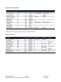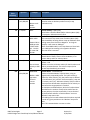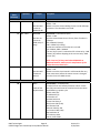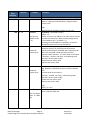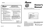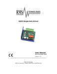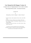
1
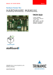
R325PE Single Axis Driver with Indexer and Encoder Reader User Manual And Commands Guide Version 3.00 RMS Technologies 2533 N. Carson St. #4698, Carson City, NV 89706‐0147 RMS Technologies R325PE Single Axis Driver Manual Page 1 Version 3.0 9/29/2014 Thank you for purchasing the R325PE Single‐Axis Driver with Indexer. This product is warranted to be free of manufacturing defects for one (1) year from the date of purchase. PLEASE READ BEFORE USING Before you start, you must have a suitable step motor, a DC power supply suitable for the motor and a current resistor. The power supply voltage must be between 4 times and 20 times the motor's rated voltage. DISCLAIMER The information provided in this document is believed to be reliable. However, no responsibility is assumed for any possible inaccuracies or omissions. Specifications are subject to change without notice. RMS Technologies reserves the right to make changes without further notice to any products herein to improve reliability, function, or design. RMS Technologies does not assume any liability arising out of the application or use of any product or circuit described herein; neither does it convey any license under its patent rights, nor the rights of others. Special Symbols Indicates a WARNING and that this information could prevent injury, loss of property, or even death (in extreme cases). RMS Technologies R325PE Single Axis Driver Manual Page 2 Version 3.0 9/29/2014 R325PE User Manual Product: R325PE Version: 3.0 Date: 9/29/2014 Version History Version Date Description of Changes 1.00 01/31/2013 New User Manual 2.00 05/29/2013 Updated enable/disable pin description on page 8. 3.00 9/29/2014 Updated default Baud rate to 57600 (typo) RMS Technologies R325PE Single Axis Driver Manual Page 3 Version 3.0 9/29/2014 Table of Contents 1. FEATURES .......................................................................................... 5 2. ELECTRICAL SPECIFICATIONS...................................................................... 5 3. OPERATING SPECIFICATIONS ..................................................................... 6 4. MECHANICAL SPECIFICATIONS ................................................................... 6 6. CONNECTION SPECIFICATIONS ................................................................... 8 Connecting the Power ................................................................................................ 9 Connecting the Motor ................................................................................................ 9 Configure the R325 using the DIP Switch .......................................................................... 11 DIP Switch Run Current Settings .............................................................................................. 11 DIP Switch Hold Current Settings ............................................................................................. 11 DIP Switch Step Resolution Settings .......................................................................................... 11 8. COMMAND TABLES .............................................................................. 13 Basic Configuration Commands..................................................................................... 13 Axis Configuration Commands ...................................................................................... 13 General Operation Commands ..................................................................................... 14 General Operation Commands ..................................................................................... 14 10. COMMANDS .................................................................................... 15 HOMING & POSITIONING ........................................................................................... 16 VELOCITY & ACCELERATION ........................................................................................ 16 SETTING CURRENT ................................................................................................... 19 STORAGE & RECALL .................................................................................................. 19 MICROSTEPPING ..................................................................................................... 20 QUERY COMMANDS ................................................................................................. 21 ENCODER VERSION COMMANDS ................................................................................... 22 10. Troubleshooting ................................................................................ 24 11. Appendix A...................................................................................... 25 11. Appendix B ...................................................................................... 29 RMS Technologies R325PE Single Axis Driver Manual Page 4 Version 3.0 9/29/2014 1. FEATURES Single Axis Driver with indexer for Bipolar step motors Encoder readout function available Operates from +12 to 48 VDC Phase currents from 0.3 to 3.0 Amp Peak NOTE: Phase current of 2.7 Amp and above REQUIRES an additional heatsink, make sure the temperature of the bracket does not exceed 45° C. Hold current reduction capability with adjustable current and timeout settings Selectable Step Resolution from Full Step to 256x Microstepping Has three optically isolated control inputs and one optically isolated control output Pole Damping Technology™ integrated within driver board Dip switches and a RS485 interface are built‐in to the R325P Controller. A USB connection can be used by using the USB485 Converter Card (sold separately). 2. ELECTRICAL SPECIFICATIONS Supply Voltage: +12 to 48 VDC Phase Current: 0.3 to 3.0 Amps Peak NOTE: Phase current of 2.7 Amp and above REQUIRES an additional heatsink, make sure the temperature of the bracket does not exceed 45° C. I/O Specifications 3x Optically Isolated Inputs (1 fixed) 1x Optically Isolated Output Minimum Motor Impedance: 1.5 mH Note: The drive may behave unpredictably if the motor you are using has an inductance less than 1.5 mH. RMS Technologies R325PE Single Axis Driver Manual Page 5 Version 3.0 9/29/2014 3. OPERATING SPECIFICATIONS Maximum Step Frequency: Operating Temperature: 2.5 MHz Low end – 0° C High end – Dependent on case temperature, bracket temperature must not exceed 45° C Automatic Motor Holding Current reduction available from 0.3 to 2.5 Amps Logic Timing Minimum Step Pulse Width 200 nanoseconds Minimum Step Low Time 200 nanoseconds Maximum Power‐Down Recovery Time 20 milliseconds 4. MECHANICAL SPECIFICATIONS Size: 3.00” x 2.75” x 1.42” Weight: 3.2 oz Mounting: Four #6‐32 screws, 2.42” x 2.45” Plate: Aluminum, Hard Anodized Figure 4.1 RMS Technologies R325PE Single Axis Driver Manual Page 6 Version 3.0 9/29/2014 5. PIN ASSIGNMENTS Mating Connectors P1 P2 P3 AMP 640441‐3 AMP 640441‐5 Phoenix 1803675 P1 – RS485 bus Interface P1 Configuration Pin No Function 1 A Input (+ve) 2 Ground 3 B Input (‐ve) Table 5.1 P1 & P2 Location of Pin 1 Inage 5.1 P2 – Encoder Interface P2 Configuration Pin No Function 1 Ground 2 Index 3 A 4 +5VDC 5 B Table 5.2 A motor with a single ended optical encoder must be used in order for the encoder feedback function to work. Connect the 5 wires from the encoder into P2 using a 5‐Pin to 5‐Pin connector which is provided with the Designer’s Kit (purchased separately). P3 – Motor/Controls/Power Interface A 12‐pin pluggable terminal strip connector P3 provides power and the step and direction control functions for the module. All of these signals are optically isolated. Open‐collector drives are required to provide pulses for Step, levels for Direction, and Disable. The common +ve supply ranges from 5 VDC to 30 VDC with respect to the signal input; however if the supply is greater than 5 VDC then a resistor must be inserted in series with each signal line to limit the current to 10 mA. P3 Configuration Pin No Function 1 Common +ve External 2 Step (in) 3 Direction (in) 4 +5 VDC Internal 5 Disable (in) 6 Motor A+ (out) 7 Motor A‐ (out) P3 Connector – Pin 1 Location 8 Motor B+ (out) Inage 5.2 9 Motor B‐ (out) 10 Full Step Output 11 Power Ground 12 Power Positive Table 5.3 RMS Technologies Page 7 Version 3.0 R325PE Single Axis Driver Manual 9/29/2014 CAUTION: Connecting Motor phases (A, A Bar, B, B Bar) to the incorrect location while the R325P is powered will cause the board to burn. Be sure to insert motor phases into Pins 6 through 9, in the order of A, A Bar, B, and B Bar. It is recommended that power is connected last, so that all connections can be checked before power up. 6. CONNECTION SPECIFICATIONS When using the Driver Only portion of the R325PE, use the dip switches for step resolution and current settings. Using the R325PE as a Driver Unit Only Step 1: Take off the jumper located on J1 Remove the jumper from J1 in order for the R325PE to The jumper can be placed on 1 pin so that it is not misplaced. function as a driver ONLY. Inage 6.2 Image 6.1 If using the R325PE as a Driver only, be sure to connect the power supply last. Pin 1: Connect Pin 1 to Pin 4 to use the internal +5VDC. By using the internal +5VDC the I/O’s will no longer be optically isolated. If optical isolation is still desired, use a separate +5VDC supply and connect the POSITIVE end of the supply to Pin 1. The NEGATIVE end will connect with the NEGATIVE end of your pulse generator. Pin 2: Use a pulse generator or function generator to receive pulses into the R325P. Connect the POSTIVE end of the pulse generator to Pin 2. The NEGATIVE end will be connected to the NEGATIVE end of the +5VDC supply if using a separate power source. If using the internal +5VDC supply, connect the NEGATIVE end of the pulse generator to Power GROUND. Pin 3: To switch the direction of motor rotation, connect Pin 3 with Pin 11, Power Ground. An open or closed connection to Power Ground will change the direction. Pin 4: This is the internal +5VDC. Use this for testing purposes or if optical isolation of the inputs is not desired. It can output a max of 50 mAmps. Pin 5: To enable the drive leave this Pin open, disable the drive connect Pin 5 with Pin 11 (Power Ground). An open or closed connection to Power Ground will enable and disable the drive, respectively. A closed connection will remove all power to the output motor leads (Pins 6 through 9). RMS Technologies Page 8 Version 1.00 R325P Single Axis Driver Manual 1/31/2013 Pin 6: Phase A Motor Connection CAUTION: Connecting Motor phases (A, A Bar, B, B Bar) to the incorrect location while the R325P is powered Pin 7: Phase A Motor Connection will cause the board to burn. Be sure to insert motor phases into Pins 6 through 9, in the order of A, A Bar, B, Pin 8: Phase B Motor Connection and B Bar. It is recommended that power is connected Pin 9: Phase B Motor Connection last, so that all connections can be checked before power up. Pin 10: When using the R325PE in Full Step mode, this output goes high. Pin 11: Connect the NEGATIVE of the Power Supply to this terminal. Pin 12: Connect the POSITIVE of the Power Supply to this terminal. (+12 to 48VDC) Connecting the Power The R325P requires a supply voltage between 12‐48 VDC. First, connect the positive end of the power supply to positive terminal (Pin 12), and then connect the negative of the power supply to the Ground (Pin 11) on the R325P. WARNING! Be careful not to reverse the polarity from the power supply to the driver. Reversing the connection will destroy your driver and void the warranty. Connecting the Motor WARNING! Make sure the power is OFF when connecting or disconnecting motors from the R325P. Damage will occur if the power is being supplied. Please refer to your motor documentation for wiring color code. Connect the corresponding Phase from the motor to the proper pin on the R325PE. Motor Phase P1 Connector Phase A Pin 6 Phase A‐ Pin 7 Phase B Pin 8 Phase B‐ Pin 9 RMS Technologies R325P Single Axis Driver Manual Page 9 Version 1.00 1/31/2013 Figure 6.1 Using the R325P with more than 5V You can choose to supply the optos with the R325P’s internal 5V supply by jumping pins 1 to 4. But if you choose to use more than 5V, for example, a 24V supply and the step pulse train is also a 0 to 24V low‐high signal, please use the following recommended resistor to limit the current to 10 mAmps. Note: no resistor will be needed on the actual opto supply line, pin 1. Step & Direction lines have a 470 ohm internal resistor Voltage: Ohms needed: Wattage rating: 5V 0 0 10V 500 ¼ watt Table 6.1 12V 1000 ¼ watt 24V 2000 ¼ watt Disable line has a 1k ohm internal resistor Voltage: Ohms needed: Wattage rating: 5V 0 0 10V 1000 1/8 watt Table 6.2 12V 1900 1/8 watt 24V 3800 ¼ watt RMS Technologies Page 10 R325PE Single Axis Closed loop Driver/Indexer Manual Version 3.0 9/29/2014 Configure the R325P using the DIP Switch R325P DIP Switch Settings Run Current Function SW1 SW2 SW3 SW4 0.3A ON ON ON ON 0.4A OFF ON ON ON 0.5A ON OFF ON ON 0.6A OFF OFF ON ON 0.8A ON ON OFF ON 1.0A OFF ON OFF ON 1.2A ON OFF OFF ON 1.4A OFF OFF OFF ON 1.6A ON ON ON OFF 1.8A OFF ON ON OFF 2.0A ON OFF ON OFF 2.2A OFF OFF ON OFF 2.4A ON ON OFF OFF 2.6A OFF ON OFF OFF 2.8A ON OFF OFF OFF 3.0A OFF OFF OFF OFF Table 6.3 WARNING: Current of 2.7 Amp and above REQUIRES an additional heat sink; make sure the temperature of the bracket does not exceed 45° C Hold Current (Percent of Run Current) Function SW5 SW6 0% ON ON 33% OFF ON 66% ON OFF 100% OFF OFF Table 6.4 Step Resolution Function SW7 SW8 SW9 SW10 Full Step* OFF OFF OFF OFF 2X ON OFF OFF OFF 4X ON ON OFF OFF 8X ON OFF ON OFF 16X ON ON ON OFF 32X ON OFF OFF ON 64X ON ON OFF ON 128X ON OFF ON ON 256X ON ON ON ON *The power must be turned OFF when switching in and out of Full Step mode. Table 6.5 RMS Technologies Page 11 R325PE Single Axis Closed loop Driver/Indexer Manual Version 3.0 9/29/2014 Communicating with the R325PE Step 1: Move all dipswitches to the OFF position. Place jumper on Pins 1 & 2. Jumper is placed closest to the LED. Move ALL dipswitches to the OFF Position Inage 6.3 1. Connect P1 to PC via RS485‐232 Converter Card or USB485 Converter Card. 2. Set up HyperTerminal by selecting correct COM port 3. Settings for HyperTerminal is as follows: 57600, 8 bits, None, 1, None 4. The R325P Driver only version allows for changing the hold timeout settings, the amount of mixed decay, and to check the firmware revision level. RS485‐232 Converter Card Figure 6.2 RMS Technologies Page 12 R325PE Single Axis Closed loop Driver/Indexer Manual Version 3.0 9/29/2014 USB485 Converter Card Figure 6.3 7. COMMAND TABLES The R325PE can also be used as an indexer with closed loop controls. Basic controller commands can be used but users cannot store programs to the unit. This unit is commonly used with a user‐created GUI or PLC’s that can communicate commands via ASCII and serial port. Basic Configuration Commands Query/Command Code Function Value Minimum Maximum Default Load Defaults N LD None ‐ ‐ ‐ Save Data N SD None ‐ ‐ ‐ Module Address Q/C MA Numeric 65 (A) 90 (Z) 65 (A) Baud Rate Q/C BR Numeric 9600 57600 57600 Table 7.1 Axis Configuration Commands Query/Command Code Function Value Minimum Maximum Default Acceleration Q/C AC Numeric 1 250 10 Hold Current Q/C HI Numeric 0 3000 300 Hold Timeout Q/C HT Numeric 100 5000 500 Min. Velocity Q/C MV Numeric 250 15,000 250 Percent Fast Decay Q/C PF Numeric 0 3 2 Run Current Q/C RI Binary 300 3000 1000 Read Switches Q RS Numeric 0 1023 ‐ Step Resolution Q/C SR Numeric 1 256 8 Start Velocity Q/C SV Numeric 250 15,000 1000 Velocity Limit Q/C VL Numeric 250 50,000 15,000 Zero Position C ZP None ‐ ‐ ‐ Table 7.2 RMS Technologies Page 13 R325PE Single Axis Closed loop Driver/Indexer Manual Version 3.0 9/29/2014 General Operation Commands Query/Command Function Absolute Position C Current Position Q/C Current Velocity Q Direction Velocity* C Firmware Revision Q Home Axis C Move Status Q Position Move C Step Back C Step Forward C Stop Motion C Velocity Move * Q Code AP CP CV DV FR HA MS PM SB SF SM VM Value Minimum Maximum Default Numeric ‐2,147,483,646 2,147,483,647 ‐ Numeric ‐2,147,483,646 2,147,483,647 ‐ Numeric 0 50,000 ‐ Numeric ‐50,000 50,000 ‐ Numeric ‐ ‐ ‐ Numeric 0 1 ‐ Numeric 0 2 ‐ Numeric ‐2,000,000,000 2,000,000,000 ‐ None ‐ ‐ ‐ None ‐ ‐ ‐ None ‐ ‐ ‐ Numeric ‐50,000 50,000 ‐ Table 7.3 * Velocity Moves in the range –249 to 249 are not legal except zero Encoder Commands Query/Command Code Value Function Minimum Maximum Default Current Encoder Q CE Numeric ‐16,777,215 16,777,215 ‐ Error Action Q/C EA Numeric 0 2 2 Encoder Installed Q/C EI Boolean 0 1 1 (TRUE) Encoder Lines Q/C EL Numeric 0 16,777,215 200 Encoder Mode Q/C EM Numeric 1 2 2 Error Permitted Q/C EP Numeric 0 16,777,215 Encoder Count Error Read Q ER Numeric 0 16,777,215 Home Axis HA Boolean 0 1 0 = FWD Motor Full Steps Q/C MF Numeric 0 16,777,215 200 Zero Position ZP Table 7.4 RMS Technologies Page 14 R325PE Single Axis Closed loop Driver/Indexer Manual Version 3.0 9/29/2014 8. COMMANDS Protocol Syntax Command Format: #<Address><Command><value><CR><LF> Example: #ACP1000<CR><LF> Sets Driver A to the current position of 1000 To query a command use the following format Query Format: #<Address><Command><CR><LF> Example: #AAC<CR><LF> Queries Driver A for the current Acceleration Value The response would be in the following format Response Format: *<Address><value> Example: *AAC10 The Acceleration Value for Driver A is 10 <CR><LF> stand for "Carriage Return" and "Line Feed" respectively. These are NOT characters to be typed in. For direct keyboard users, these values are executed when the "Return" key is pressed. For programmers, a "Carriage Return" and "Line Feed" (also known as a "New Line") command needs to be executed after each command. RMS Technologies Page 15 R325PE Single Axis Closed loop Driver/Indexer Manual Version 3.0 9/29/2014 Table 8.1 – List of Commands Command Operand (Case Sensitive) HOMING & POSITIONING HA 0 = Forward 1 = Reverse Example #AHA1 Motor turns in the reverse direction CP +/– #ACP1000 2,147,483,646 Sets the current position to be 1000 #ACP Returns the current position of the motor ZP ‐ #AZP VELOCITY & ACCELERATION AC 1 ‐ 250 #AAC1 Sets Acceleration to 1000 PPS^2 Description Home Axis ‐ Command Only ‐ Causes the motor to move at the preset Start Velocity (SV) in the direction set by the command value. Motion stops when the index input of a device on the input pin goes TRUE then stops and sets Absolute Position and Current Encoder to zero. Motion can also stop by the entry of a Stop Motion (SM) command. ‐ Forward is defined as the direction the motor turns when the ‘Direction’ input (P1‐3) is set TRUE, or there is no connection to this input. P2 Configuration Pin No Function 1 GND 2 Index 3 ‐ 4 +5 V 5 ‐ Table 8.2 Current Position ‐ Command or Query. ‐ Returns the absolute position of the axis if no value is passed. Valid after power cycles if a Save Data Command is issued before power down. Can be used to set current position value. The units are steps at the current step resolution (value becomes invalid with step resolution changes). The absolute position scale is set to zero by the Zero Position command (ZP) or the execution of a Home Axis (HA) command. Zero Position ‐ Command Only ‐ Sets the Current Position and the Encoder Position to zero Note: This command functions differently between R325I and R325IE Acceleration ‐ Command or Query Default = 10 Used to shape the acceleration and deceleration ramps of position moves, and the rate of velocity change for velocity moves. Does not affect any of the basic step and direction move operations. Acceleration Factor * 1000 Pulses per Second RMS Technologies Page 16 R325PE Single Axis Closed loop Driver/Indexer Manual Version 3.0 9/29/2014 Command Operand Example (Case Sensitive) VELOCITY & ACCELERATION (cont.) AP +/– #AAP1000 2,147,483,646 Moves to the 1000th position. CV +/‐ 50,000 #ACV DV +/‐ 50,000 MS 0 ‐2 #ADV1000 #ADV‐1000 Rotates CW at 1000 pps then CCW at 1000 pps. Use this to rotate CW & CCW. #AMS Description Absolute Position ‐ Command Only ‐ Used to make an absolute position move (in step resolution units). Current Velocity ‐ Query Only ‐ Used when a Position Move (PM) or Velocity Move (VM) is in progress. Otherwise returns zero. Direction Velocity – Command Only ‐This command is the exact same as Velocity Move (VM) with the addition of being able to ramp up and down when making moves from Positive to Negative. In the given example, it will rotate at 1000 pps. When issued #ADV‐1000, it will ramp down to 0 then back up to 1000 pps but rotating in the opposite direction. Note: No value is returned. Move Status ‐ Query Only ‐ Reads Motion Status. Returns 0 for No Motion, 1 for Position Move, and 2 for Velocity Move. Minimum Velocity ‐ Command or Query MV 250 ‐ 15,000 #AMV500 Default = 250 Sets minimum ‐ Reads or sets the minimum velocity for both Position and velocity to 500 Velocity command moves. The units are steps (at the current Step Resolution) per second. SPS Position Move ‐ Command Only PM +/‐ #APM1000 ‐ Causes a ‘Relative Motion’ Position Move, using an 2,000,000,000 Makes a 1000 approximately trapezoidal profile. The initial velocity is defined by ‘Start Velocity’ (SV), the profile ramp is defined step move by ‘Acceleration’ (AC), and the ‘Constant Velocity’ step rate from the current by ‘Velocity Limit’ (VL). ‘Minimum Velocity’ (MV) is used to position ensure that the deceleration ramp does not set velocity to zero before the target position is reached. ‐ It should be remembered that, while the ‘Position Move’ value defines the number of steps to be made from the current position, the value returned by ‘Current Position’ (CP) both before and after a ‘Position Move’ are on an ‘Absolute’ step count scale. ‐ CP readings can be used to determine PM values required to reach any given position on the ‘Absolute’ step count scale. Note: This command does not return a value. RMS Technologies Page 17 R325PE Single Axis Closed loop Driver/Indexer Manual Version 3.0 9/29/2014 Command Operand Example (Case Sensitive) VELOCITY & ACCELERATION (cont.) SB ‐ #ASB Moves one step back SF ‐ #ASF Moves one step forward SM ‐ #ASM Stops any Position or Velocity move in progress #ASV500 Start velocity set to 500 PPS SV 250 – 15,000 VL 250 – 50,000 VM +/‐ 50,000 #AVL5000 Sets the velocity limit to 5000 steps/sec #AVM1000 Starts a velocity move of 1000 steps per second Use this to jog continuously in one direction. Description Step Back ‐ Command Only ‐ Makes a single step move at the current step resolution ‐ Forward is defined as the direction the motor moves with the ‘Direction’ input in the FALSE state or with no connection. Backwards is thus the direction the motor moves when the ‘Direction’ input is in the energized or TRUE state. Step Forward ‐ Command Only ‐ Makes a single step move at the current step resolution ‐ Forward is defined as the direction the motor moves with the ‘Direction’ input in the FALSE state, or with no connection. Backwards is thus the direction the motor moves when the ‘Direction’ input is in the energized or TRUE state. Stop Motion Command Only ‐ This command can be used to affect an end to any Position Move or Velocity Move in progress. It has no effect on motion produced by the Step and Direction inputs. Start Velocity ‐ Command or Query Default = 1000 ‐ Reads or sets the velocity used for the first step in a position move in steps/sec. Value based on motor performance. This command must be used with Position Move (PM) command Velocity Limit ‐ Command or Query Default = 15000 ‐ Reads or sets the velocity used for Velocity Moves and the constant velocity portion of a Position Move. Velocity Move ‐ Command Only ‐ The sign of the value determines the direction (positive for forward and negative for backward) in which the velocity move is made. The value sets the step rate in steps per second at the current step resolution. Velocity cannot exceed Velocity Limit. ‐ The move begins at the set ‘Minimum Velocity’ (MV) with the speed ramping to the command velocity at the rate set by ‘Acceleration’ (AC). Used for jogging in 1 direction. ‐ Changes to new velocity values from new VM commands, will also occur at the rate set by ‘Acceleration’ (AC). Note: No value is returned. Zero velocity makes an abrupt stop RMS Technologies Page 18 R325PE Single Axis Closed loop Driver/Indexer Manual Version 3.0 9/29/2014 Command Operand (Case Sensitive) SETTING CURRENT HI 0‐3000 RI 300 ‐ 3000 HT 100 ‐5000 STORAGE & RECALL LD ‐ Example #AHI300 Sets the Hold Current to 300mA (0.3A) #ARI1000 Sets the run current to 1000 mA (1.0 Amp) #AHT100 Sets the Hold Timeout to 100 mS #ALD Loads all the default values Description Hold Current ‐ Command or Query ‐ 0 to 3000 Default = 300 ‐ Reads or sets the motor Holding Current in 100 milliamps increments. The value does not round. Run Current ‐ Command or Query Default = 1000 ‐ Sets the motor Phase Current for any form of motion in milliamps. 300 = 300mA (0.3 Amp) 2500 = 2500mA (2.5 Amp) The last two numbers of the value are not read. 350 = 300mA, 2499 = 2400mA ‐ The set ‘Run Current’ is maintained for a time set by ‘Hold Timeout’ (HT) before dropping to the current set by ‘Hold Current’ (HI) NOTE: Current of 2.7 Amp and above REQUIRES an additional heatsink, make sure the temperature of the bracket does not exceed 45° C Hold Timeout ‐ Command or Query Default = 500 ‐ Reads or sets the time interval in milliseconds after any motor movement, before the motor current is changed from Run Current to Hold Current. Load Defaults ‐ Command Only ‐ Loads all of the unit Default parameter values. A Save Data (SD) command must be issued to have these values retained during a power cycle. Default values are: My Address 65 (A) Acceleration 10 Absolute Position 0 Percent Fast Decay 2 Hold Current 300 (0.3A) Hold Timeout 500 Minimum Velocity 250 Run Current 1000 (1.0A) Step Resolution 8 Start Velocity 1000 Velocity Limit 15000 RMS Technologies Page 19 R325PE Single Axis Closed loop Driver/Indexer Manual Version 3.0 9/29/2014 Command Operand (Case Sensitive) SD ‐ Example #ASD Saves data MISC PF 0, 1, 2, 3 MICROSTEPPING SR 1, 2, 4, 8, 16, 32, 64, 128, 256 #ACD1 Sets Mixed Mode damping to 15% #ASR4 Sets the step resolution to 4x Description Save Data ‐ Command Only ‐ This command causes a set of parameter values to be written to non‐volatile memory. On power up the last set of values written are set to be the parameter initial values. ‐The parameters whose values are thus saved are: My Address Absolute Position Velocity Limit Minimum Velocity Start Velocity Acceleration Hold Timeout Step Resolution Run Current Hold Current Percent Fast Decay Percent Fast Decay ‐ Command or Query Default = 2 ‐ Allows the Damping Mode of the driver IC to be set. 0 = Fast Decay 1 = Mixed Mode 15% 2 = Mixed Mode 48% 3 = 100% The optimum setting will vary with motor inductance and step rate; however the default ‘Mixed Mode’ setting will work well with almost all motors. Step Resolution ‐ Command or Query Default = 8 ‐ Reads or sets the current step resolution Allowed values are: 256 for 256x 128 for 128x 64 for 64x 32 for 32x 16 for 16x or 8 for 1/8th stepping 4 for 1/4 stepping 2 for Half Stepping 1 for Full Stepping RMS Technologies Page 20 R325PE Single Axis Closed loop Driver/Indexer Manual Version 3.0 9/29/2014 Command Operand (Case Sensitive) QUERY COMMANDS FR ‐ Example #AFR MA 65 ‐ 90 #AMA88 Sets the unit address to 88 (‘X’) RS 0‐1023 #ARS Reads the switch inputs TI ‐ #ATI Reads the switch inputs BR 9600 – 57600 #ABR9600 Sets the Baud Rate to 9600 bps Description Firmware Revision ‐ Query Only ‐ Returns 3 digit part code followed by 3 digit firmware revision value. Reply *AFR325PEV100 //R325PE firmware revision 1.00 My Address ‐ Command or Query Default = 65 ‐ Reads or sets the unit address. The value read or entered is the decimal value of the ASCII character designated as the unit address. (65 = ‘A’ and 90 = ‘Z’) The change to a new address is immediate, in that the command response will use the new address Read Switches ‐ Query Only ‐ Reads the TRUE (1) or FALSE (0) state of the three optically coupled inputs, combined into a single three‐bit value. This command is used to check the correct operation of this interface. ‐ The value order of the inputs is ‘Direction’, ‘Disable’, and ‘Step’; in descending order. ‘Direction’ has the value 4 (100) ‘Disable’ has the value 2 (010) ‘Step’ has the value 1 (001) Test Inputs ‐ Query Only Step, Direction, and Disable all return a value in decimal form. The value order of the inputs is: ‘Direction’, ‘Disable’, and ‘Step’; in descending order. ‘Direction’ has the value 4 (100) ‘Disable’ has the value 2 (010) ‘Step’ has the value 1 (001) Reply *ATI3 // 3 = ‘011’ Baud Rate – Query and Command Sets or reads the baud rate. RMS Technologies Page 21 R325PE Single Axis Closed loop Driver/Indexer Manual Version 3.0 9/29/2014 Command Operand Example (Case Sensitive) ENCODER VERSION COMMANDS EM 1, 2 #AEM2 Sets the Encoder Mode to 2 EI 0, 1 EL 0 ‐ 16777215 #AEI1 Encoder Installed True #AEL400 Sets the encoder line count to 400 CE +/‐ 16777215 (Motor Position in Encoder counts) #ACE *ACE12345 EA 1, 2 #AEA2 Sets Error Action to Correct Mode #AEP10 EP 0 – 16777215 Description Encoder Mode – Command or Query, Default = 2 ‐ Reads or sets the operating mode of the Encoder Interface IC. A value of 1 returns one Encoder Count per Encoder Line. A value of 2 returns 2 Encoder Counts per Encoder Line. Only 1 and 2 are valid. (3x or Quadrature 4x is not permitted on this device). This is the first encoder setting to use. Encoder Installed – Command or Query, Default = 1 ‐ Read or set TRUE (1) or FALSE (0). This is the second encoder setting to enter in order to get started. Encoder Lines – Command or Query, Default = 400 ‐ Encoder lines per motor revolution ‐ Reads or sets the encoder line count. This is used in conjunction with Encoder Mode to calculated motor positions. Use EL with EM, Encoder Mode. For example, if EM=2 (default) and if your encoder is 400 CPR, then EL should be 2 x 400 = 800. Current Encoder – Query Only ‐ Returns a 16‐bit signed value, corresponding to the current motor position in encoder count. (See Encoder Mode). This is the main usage of the encoder. A separate PLC or controller can query the encoder position and compare it to the Current Position (CP), and issue adjusted moves based on the error seen. Error Action – Command or Query, Default = 2 ‐ Reads or sets a value that determines the action to be taken when an encoder error is found 1 – The error is reported and the motor is stopped 2 – The error is reported and the correction move is made Error Permitted‐ Command or Query ‐ Reads or sets the maximum error allowed before Error Action is taken. Depending on the system configuration, the value is given in either Encoder Counts or Steps at the current Step Resolution. ‐ If the product of Encoder Lines and Encoder Mode is larger than the product of Motor Steps and Step Resolution, then the value is in Encoder Counts. Otherwise it is in Steps. Note: The minimum value is the number of the finer resolution Encoder Counts or Steps required to make up one unit of the coarser resolution. RMS Technologies Page 22 R325PE Single Axis Closed loop Driver/Indexer Manual Version 3.0 9/29/2014 ER 0 ‐ 16777215 #AER *AER5 MF ‐ #AMF200 Sets Motor Fullsteps to 200 Error Read – Query Only ‐ Returns the current Encoder Error value. If the product of Encoder Lines and Encoder mode is larger than the product of Motor Steps and Step Resolution, then the error is in Encoder Counts. Otherwise it is in Steps. Motor Fullsteps (per revolution) – Command or Query Default = 200 Reads or sets the number of Fullsteps per motor revolution, i.e. A 1.8° motor will have a Fullstep count of 200. Motion Profile Commands Velocity DV+ VL VM AC AC SV MV Time DV‐ Graph 8.1 SV: Start Velocity – the very first step it takes begins with the start velocity value (must be ≥ MV) MV: Minimum Velocity AC: Acceleration (and deceleration) VL: Velocity Limit – sets the max speed the motor will rotate during a VM, PM or DV move command VM: Velocity Mode – rotates the motor at a fixed speed for continuous motion (use this to jog 1 direction only) DV: Direction Velocity – rotates the motor at a fixed speed for continuous motion, but allows the motor to change direction of rotation smoothly. Use this command rather than the VM command if jogging CW and CCW RMS Technologies Page 23 R325PE Single Axis Closed loop Driver/Indexer Manual Version 3.0 9/29/2014 9. Troubleshooting R325P is not functioning correctly Try putting the R325P into TEST mode by placing a jumper on Pins 3 & 4 of J1 as shown below. The motor should twitch back and forth slightly if the R325P is functioning properly. R325P not moving the motor (Step/Dip) Verify that the 5V is being supplied to Pin 1. The R325P is causing the motor to vibrate and jitter back and forth Are the Motor phases switched? Be sure to check that motor wires are connected to Pins 6 through 9, in the order of A, A Bar, B, B Bar. To check which wires belong to one phase, take a Meter to measure resistance between any two wires. If there is a finite value between two of them, insert the wires into pins 6 and 7, OR pins 8 and 9. Insert the remaining two wires accordingly. Technical Support By Telephone: 408‐919‐0200 (Monday‐Friday; 8:00 AM ‐ 5:00PM Pacific) On the Web: www.linengineering.com Our technical support group is glad to work with you in answering your questions. If you cannot find the solution to your particular application, or, if for any reason you need additional technical assistance, please call technical support at 408‐919‐0200. RMS Technologies Page 24 R325PE Single Axis Closed loop Driver/Indexer Manual Version 3.0 9/29/2014 10. Appendix A: Recommended Cable Recommended Cable Configurations: DC Supply to Driver Cable length, wire gauge and power conditioning devices play a major role in the performance of your RMS Technologies Driver and Motor. NOTE: The length of the DC power supply cable to the Driver should not exceed 50 feet. Example A – Cabling Under 50 Feet, DC Power Example A demonstrates the recommended cable configuration for DC power supply cabling under 50 feet long. If cabling of 50 feet or longer is required, the additional length may be gained by adding an AC power supply cable. Correct AWG wire size is determined by the current requirement plus cable length. Please see the Driver Supply Cable AWG Table in this Appendix. RMS Technologies Page 25 R325PE Single Axis Closed loop Driver/Indexer Manual Version 3.0 9/29/2014 NOTE: These recommendations will provide optimal protection against EMI and RFI. The actual cable type, wire gauge, shield type and filtering devices used are dependent on the customer’s application and system. Driver Supply Cable AWG Table 1 Amp (Peak) Length (Feet) 10 25 50* 75* 100* Minimum AWG 20 20 18 18 16 2 Amps (Peak) Length (Feet) 10 25 50* 75* 100* Minimum AWG 20 18 16 14 14 3 Amps (Peak) Length (Feet) 10 25 50* 75* 100* Minimum AWG 18 16 14 12 12 * Use the alternative methods illustrated in Examples B and C when the cable length is ≥ 50 feet. Also, use the same current rating when the alternate AC power is used Driver Supply Cable Wire Size NOTE: Always use Shielded/Twisted Pairs for the Driver DC Supply Cable, the AC Supply Cable and the Driver to Motor Cable. RMS Technologies Page 26 R325PE Single Axis Closed loop Driver/Indexer Manual Version 3.0 9/29/2014 Recommended Cable Configurations: Driver to Motor Cable length, wire gauge and power conditioning devices play a major role in the performance of your Driver and Motor. NOTE: The length of the DC power supply cable between the Driver and the Motor should not exceed 50 feet. Example A demonstrates the recommended cable configuration for the Driver to Motor cabling under 50 Feet long. Correct AWG wire size is determined by the current requirement plus cable length. Please see the Driver to Motor Cable AWG Table in this Appendix. Example A ‐ Cabling Under 50 Feet, Driver to Motor If cabling of 50 feet or longer is required, the additional length can be gained by adding Common Mode Line Filters (2x) *L ≈ 0.5 MH RMS Technologies Page 27 R325PE Single Axis Closed loop Driver/Indexer Manual Version 3.0 9/29/2014 * 0.5 MH is a typical starting point for the Common Mode Line Filters. By increasing or decreasing the value of L you can set the drain current to a minimum to meet your requirements. Driver to Motor Cable AWG Table 1 Amp (Peak) 5 Amp (Peak) Length (Feet) 10 25 50 75 100 Length (Feet) 10 25 50 75 100 Minimum Minimum 20 20 18 18 16 16 16 14 12 12 AWG AWG 2 Amp (Peak) 6 Amp (Peak) Length (Feet) 10 25 50 75 100 Length (Feet) 10 25 50 75 100 Minimum Minimum 20 18 16 14 14 14 14 14 12 12 AWG AWG 3 Amp (Peak) 7 Amp (Peak) Length (Feet) 10 25 50 75 100 Length (Feet) 10 25 50 75 100 Minimum Minimum 18 16 14 12 12 12 12 12 12 12 AWG AWG 4 Amp (Peak) Length (Feet) 10 25 50 75 100 Minimum 18 16 14 12 12 AWG Driver to Motor Supply Cable Wire Size NOTE: These recommendations will provide optimal protection against EMI and RFI. The actual cable type, wire gauge, shield type and filtering devices used are dependent on the customer’s application and system. NOTE: Always use Shielded/Twisted Pairs for the Driver DC Supply Cable, the AC Supply Cable and the Driver to Motor Cable. RMS Technologies Page 28 R325PE Single Axis Closed loop Driver/Indexer Manual Version 3.0 9/29/2014 11. Appendix B: PF Value For applications requiring ultimate smoothness of motion and extreme accuracy, the R325P driver can be programmed via RS485 to change the Percent Fast Decay rate, or, the PF value. The Percent Fast Decay default is 2, or a mixed mode of 48%. Mixed mode is a damping technique done to the driver IC. The following values indicate the choices for Percent Fast Decay: PF Values (0 through 3): 0 = Slow Decay 1 = Mixed Mode 15% 2 = Mixed Mode 48% 3 = 100% Fast Decay Generally speaking, applications that run at slow speeds are recommended to use a PF value of 1 or less. Fast speeds should use a PF value of 2 or more. Since the best PF value is dependent on the motor winding, loads, power supply voltage, and other factors, it is best to use an oscilloscope and a current probe device to view the current waveform and try different PF values. The following examples show good and bad waveforms when choosing different PF values. PF value 1 Slow speeds Good waveform RMS Technologies Page 29 R325PE Single Axis Closed loop Driver/Indexer Manual Version 3.0 9/29/2014 PF value 3 Slow speeds Bad waveform PF value 1 Fast speeds Bad waveform RMS Technologies Page 30 R325PE Single Axis Closed loop Driver/Indexer Manual Version 3.0 9/29/2014