1
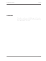
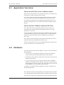
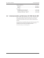
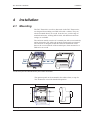
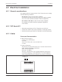
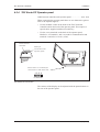
TAC Xenta 901
Handbook
}
}
24 V AC Comm
(19-40 V DC)
~ 0
G G0 C1C2
1 2 3 4 5 6 7 8 9 10
PC
12 13 14 15 16 17 18
20
TAC
Vista
TAC
Vista
Modem
Public
Modem
network
Modem
TAC Xenta 901
TAC X
LonWorks TP/FT-10
LonWorks T
Other
LonWorksproduct
I/O- module
0-004-7660-0 (GB), 1999-01-12
I/O- module
TAC Xenta 103
TAC Xenta 301
TAC Xenta 901 Handbook
Foreword
Foreword
This handbook describes the serial LonTalk adapter TAC Xenta 901, a
unit which makes it possible to reach TAC Xenta networks by dial-up
from a supervisory TAC Vista system.
TAC AB, 1999-01-12
0-004-7660-0 (GB), i (2)
TAC Xenta 901 Handbook
Foreword
List of revisions
Part no.
Comment
Author
0-004-7660-0
Original edition.
KW
ii (2), 0-004-7660-0 (GB)
Date
1999-01-12
TAC AB, 1999-01-12
TAC Xenta 901 Handbook
Contents
TAC Xenta 901 Handbook
This document contains proprietary information of TAC AB and is made available solely to those who operate and maintain TAC AB equipment. Disclosure,
reproduction or use of either the documents or the information contained herein for any other purpose is strictly prohibited.
TAC AB reserves the right to make changes or additions to material as necessary.
© 1999 TAC AB
Contents
1
1.1
1.2
1.3
2
2.1
2.2
2.3
2.4
2.3
3
3.1
3.1.1
3.1.2
3.1.3
3.1.4
3.2
4
4.1
4.2
4.2.1
4.2.2
4.2.3
4.2.4
Introduction ................................................................................................................. 1:1
TAC Xenta 901 ................................................................................................................................... 1:1
This manual ........................................................................................................................................ 1:1
More information............................................................................................................................... 1:2
TAC Xenta 901 in Dial-up systems ............................................................................ 2:1
General ............................................................................................................................................... 2:1
Modem and Dial-up functions .......................................................................................................... 2:2
Application functions ......................................................................................................................... 2:3
Hardware ............................................................................................................................................ 2:3
Communications ................................................................................................................................ 2:4
Technical description .................................................................................................. 3:1
TAC Xenta 901 Adapter .................................................................................................................... 3:1
Terminals ............................................................................................................................................. 3:1
Contacts ............................................................................................................................................... 3:1
Indicators and Service pin ................................................................................................................... 3:2
Technical data ...................................................................................................................................... 3:2
Communication performance for TAC Xenta 901 .......................................................................... 3:3
Installation ................................................................................................................... 4:1
Mounting ............................................................................................................................................ 4:1
Electrical installation ......................................................................................................................... 4:2
General considerations ........................................................................................................................ 4:2
TAC Xenta 901 .................................................................................................................................... 4:2
Cables .................................................................................................................................................. 4:2
TAC Xenta OP Operator panel ............................................................................................................ 4:5
TAC AB, 1999-01-12
0-004-7660-0 (GB), 1 (2)
TAC Xenta 901 Handbook
5
Commissioning ............................................................................................................ 5:1
5.1
5.2
5.2.1
6
Contents
General ............................................................................................................................................... 5:1
The TAC Xenta 901 ............................................................................................................................ 5:2
Initial checking .................................................................................................................................... 5:2
The TAC Xenta OP Service menu .............................................................................. 6:1
Index
Reply form
This manual contains a total of 18 leaves.
®TAC Xenta and TAC-Vista are registered trademarks of TAC, Sweden.
®Echelon, LON, LonTalk, LONWORKS and Neuron are registered trademarks of Echelon Corporation, California, USA.
™LONMARK and LonMaker are trademarks of Echelon Corporation, California, USA.
MetraVision™ is a trademark of Metra Corporation, USA.
2 (2), 0-004-7660-0 (GB)
TAC AB, 1999-01-12
TAC Xenta 901 Handbook
1
Introduction
Introduction
1.1 TAC Xenta 901
TAC Xenta 901 is a component in the TAC Xenta product family,
based on common hardware.
Please note!
The TAC Xenta 901 controller and the other products of the Xenta
family must not be used for any other purpose than that for which it
was designed.
Installation, connection and repair may only be performed by
authorized personnel.
1.2 This manual
The handbook has the following contents:
Chapter 2
This chapter contains general information about the TAC Xenta 901.
Chapter 3
The chapter contains technical information about the TAC Xenta 901.
Chapter 4
This chapter shows how to install TAC Xenta 901.
Chapter 5
This chapter contains information on how to commission
TAC Xenta 901.
TAC AB, 1999-01-12
0-004-7660-0 (GB), 1:1 (2)
TAC Xenta 901 Handbook
Introduction
Chapter 6
This chapter describes the service menu of TAC Xenta OP and how
to use it to get certain information about the system.
At the end of the manual there is a reply form, which you can fill in
if you have any comments on this handbook.
1.3 More information
The TAC Xenta controllers and TAC Xenta OP are also described in
the following documents:
• the “TAC Xenta 300 Handbook”, art.nr 0-004-7470.
• the “TAC Xenta 400 Handbook”, art.nr 0-004-7520.
• the “TAC Xenta OP Handbook”, part no. 0-004-7506
• the “TAC Xenta Network guide”, part no. 0-004-7460
• the “TAC Menta User’s manual”, part no. 0-004-7452
• the “TAC Menta Reference manual”, part no. 0-004-7453
• the TAC Xenta 901 data sheet (C-96-10)
• the TAC Xenta 300 data sheet (C-90-05)
• the TAC Xenta 401 data sheet (C-92-05)
• the TAC Xenta OP Operator panel data sheet (C-98-05)
• a brief installation instruction, “0FL”, included on delivery
1:2 (2), 0-004-7660-0 (GB)
TAC AB, 1999-01-12
TAC Xenta 901 Handbook
2
TAC Xenta 901 in Dial-up systems
TAC Xenta 901 in Dial-up systems
2.1 General
A local TAC Xenta network with a modem may be called from a
supervisory system, like TAC Vista and TAC Menta.
Controllers in a network that has been connected in this way can
exchange data in a similar way as a controller that is directly
connected. For example, it is possible to
• Read/write public variables
• Exchange alarm information
• Get trend loggings
• Perform Up/Download of the Application program and the
Network configuration
Typical configuration
A TAC Vista system connected to a modem may call any number of
modems, one at a time. Each of these modems is connected to a
TAC Xenta 901 Serial LonTalk Adapter.
TAC
Vista
TAC
Vista
Modem
Public
network
Modem
Modem
TAC Xenta 901
TAC Xenta 901
LonWorks TP/FT-10
LonWorks TP/FT-10
Other
LonWorksproduct
TAC Xenta 401
I/O- module
I/O- module
TAC Xenta 103
TAC Xenta 301
Dial-up networks with one TAC Xenta 901 Adapter in each
In each LonWorks network only one TAC Xenta 901 Adapter is
allowed, as shown in the figure above.
TAC AB, 1999-01-12
0-004-7660-0 (GB), 2:1 (4)
TAC Xenta 901 Handbook
TAC Xenta 901 in Dial-up systems
2.2 Modem and Dial-up functions
Modem
TAC Vista contains a set of default modem parameters, which makes
it possible to call most standard modems.
However, we recommend that modems connected to TAC Xenta 901
are of the USRobotics Sportster/Voice or Flash type.
Adjusting the modem parameters in the TAC Xenta 901 is possible
from TAC Vista only.
The connection to TAC Vista of certain modems recommended by
TAC are described in installation instructions of the 0FL-type.
Dial-up
TAC Vista holds a list of available telephone numbers that are to be
used for dial-up.
From TAC Vista these and other parameters can be set:
- Number of attempts for dial-up, frequency and the setting of “Line
blocked”.
- Telephone numbers to be used by the Xenta unit to dial-up
TAC Vista; one ordinary and one alternative number.
It is also possible to disable “Line blocked” in TAC Vista and in the
TAC Xenta 901.
Disconnect
Normally, disconnect is handled by the TAC Vista part. However, in
the following cases, TAC Xenta 901 may initiate a disconnect:
- The DCD (Data Carrier Detect) signal is missing.
- No messages received during at least 60 seconds.
Modem statistics
The following items are stored in TAC Xenta 901 and in TAC Vista.
They can be read and reset from TAC Vista only.
Current status: Connected, Line engaged, etc.
Last time for statistics reset
Time for latest successful dial-up from TAC Xenta
No. of dial-up attempts from TAC Xenta
No. of failed dial-up attempts from TAC Xenta
The longest time required to dial-up from TAC Xenta
The longest dial-up time from TAC Xenta
The total dial-up time from TAC Xenta
2:2 (4), 0-004-7660-0 (GB)
TAC AB, 1999-01-12
TAC Xenta 901 Handbook
TAC Xenta 901 in Dial-up systems
2.3 Application functions
Dial-up from TAC Vista to the LonWorks network
Dial-up will automatically occur when the operator or the supervisory
system has to reach some unit in the network.
Any waiting alarm acknowledge will be transferred to the controller
as soon as connection has been established for some other reason.
It is possible to download a new Application program and/or a new
Network configuration to TAC Xenta 300 and 401 controllers after a
dial-up.
Dial-up from the LonWorks network to TAC Vista
TAC Xenta 901 collects alarm and log data from the connected
controllers and will automatically dial-up the supervisory system
when there is an alarm.
It is also possible to define the importance of different message types,
so that the dial-up will occur at low-rate periods or at other events in
stead of a call for each alarm. These conditions are specified in
TAC Vista.
The contents of the alarm stack will always be transferred as soon as
connection has been established for some reason.
The TAC Xenta 901 can be set to periodically dial-up the supervisory
system. The interval is set from TAC Vista.
2.4 Hardware
TAC Xenta 901 Serial LonTalk Adapter is a part of a system with the
following units:
• TAC Xenta 901. The adapter itself that connects the LonWorks
(TAC Xenta) network with the RS232 part of the modem.
• The Modem, for the dial-up connection between the central system
and the local network.
• TAC Xenta OP, an easy-to-use operator panel, with a minimum
number of push buttons and a display. The values are presented in
plain language in a menu system. TAC Xenta OP can be connected
to the adapter or to any controller in the network.
A number of controllers and I/O modules can form a local network
and interchange data.
TAC Xenta 901 uses the same hardware as TAC Xenta 401 and works
as an interface between the RS232 and the LonWorks communication.
Only one TAC Xenta 901 is allowed in each local LonWorks network.
TAC AB, 1999-01-12
0-004-7660-0 (GB), 2:3 (4)
TAC Xenta 901 Handbook
TAC Xenta 901 in Dial-up systems
The TAC Xenta 901
12 13 14 15 16 17 18
20
Operator panel
TAC Xenta Operator panel and the TAC Xenta 901 Serial LonTalk Adapter
The TAC Xenta OP operator panel is used to give the user access to
certain parameters on the local level. It may also be used to initiate a
dial-up from the local network to the central system.
To each controller at most two OPs may be connected.
2.3 Communications
The TAC Xenta unites communicate with each other in a network
using the LONWORKS TP/FT-10 78 kbps (FTT-10) protocol.
For further details, please consult the “TAC Xenta Network guide”.
RS232
TAC Xenta 901 has an RS232 port. This port is used to:
• download network configuration information from the configuration tool in TAC Menta to TAC Xenta 901,
• connect the local network to TAC Vista directly or via a modem.
TAC Xenta 901 can perform the following communication:
• communicate with TAC Vista,
• communicate with TAC Menta,
• communicate with TAC Xenta controllers to collect alarm and
logging data,
• communicate with the operator panel,
• initiate a dial-up upon request from the OP
(please refer to chapter 6).
2:4 (4), 0-004-7660-0 (GB)
TAC AB, 1999-01-12
TAC Xenta 901 Handbook
3
Technical description
Technical description
3.1 TAC Xenta 901 Adapter
3.1.1 Terminals
Only four screw terminals are used, two for power supply and two for
the network communication.
}
}
24 V AC Comm
(19-40 V DC)
~ 0
G G0 C1C2
1 2 3 4 5 6 7 8 9 10
The terminals of TAC Xenta 901
3.1.2 Contacts
TAC Xenta 901 has two modular sockets on front; one for the
TAC Xenta OP operator panel and one for the RS232 connection with
the modem and TAC Menta Network Configuration Tool.
The socket for the operator panel provides the operator panel with
24 V AC.
Socket for RS232/
modem
TAC AB, 1999-01-12
Socket for the
Operator panel
0-004-7660-0 (GB), 3:1 (4)
TAC Xenta 901 Handbook
Technical description
3.1.3 Indicators and Service pin
On the front there is also a small hole through which the Service pin
may be activated.
Service pin
Red service diode to indicate a nonconfigured node, or a hw fault
Green status diode; indicator
for a running program
LEDs and Service pin of the TAC Xenta 901
Furthermore, there are two LED indicators, one red and one green.
The red service diode is mainly an error indication, but it also lights
up if the Service pin is activated.
The green status diode turns on and off every second to indicate that
the program is running.
3.1.4 Technical data
Supply voltage (G, G0) ................................ 24 V AC ±20%, 50/60 Hz
................................................................................. or 19–40 V DC
Power consumption ........................................................... max. 5 W
Ambient temperature:
Storage .................................................................. –20 °C to +50 °C
Operation .................................................................. 0 °C to +50 °C
Humidity ......................................... max. 90 % RH non condensing
Mechanical:
Enclosure ............................................................................ ABS/PC
Enclosure rating ....................................................................... IP 20
Dimensions (mm)........................................................... 90×110×77
Weight ..................................................................................... 0,5 kg
Real time clock:
Accuracy at +25 °C ......................................... ±12 minutes per year
Power failure protection ............................................................ 72 h
Program cycle time ................................................................... min. 1 s
Communication (C1–C2; polarity insensitive):
Modem ............................................... RS232, up to 9600 bps, RJ45
Network ............................... LonWorks, TP/FT-10, screw terminal
TAC Xenta OP ........................ LonWorks, TP/FT-10, modular jack
3:2 (4), 0-004-7660-0 (GB)
TAC AB, 1999-01-12
TAC Xenta 901 Handbook
Technical description
Agency compliances:
Emission ........................................................................ EN 50081-1
Immunity ....................................................................... EN 50082-1
Safety ............................................................................ EN 61010-1
Part number:
Electronics part TAC Xenta 901 ................................... 0-073-0915
Terminal part TAC Xenta 400 ....................................... 0-073-0902
Operator terminal TAC Xenta OP ................................. 0-073-0907
Connection cable Xenta – RS232 .................................. 0-073-0903
3.2 Communication performance for TAC Xenta 901
There is no fixed limit on how many units may be connected to a
local dialled-up network. However, the capacity of the modem
connection is lower than if TAC Vista is directly connected to the
network.
In normal cases, it is possible to have up to 30 base units, TAC Xenta
301/302/401 with associated I/O modules, and up to 120 other
LonWorks units connected to the dialled-up network.
The traffic intensity is the limiting factor.
TAC AB, 1999-01-12
0-004-7660-0 (GB), 3:3 (4)
TAC Xenta 901 Handbook
Technical description
Blank page.
3:4 (4), 0-004-7660-0 (GB)
TAC AB, 1999-01-12
TAC Xenta 901 Handbook
4
Installation
Installation
4.1 Mounting
The TAC Xenta 901, as well as other units in the TAC Xenta series,
are designed for mounting on a DIN rail inside a cabinet. They can
also be mounted directly on a wall. In such a case, a wide range of
standard enclosures, meeting DIN 43 880, with different enclosure
ratings, are available.
The enclosure mainly consists of a terminal part with screw terminals,
and an electronics part, where the printed circuit boards are situated.
The enclosure is designed so that the electrical installation can be
done to the screw terminals of the terminal part, when mounted on a
DIN rail or on a wall.
The terminal part and the electronics part of TAC Xenta 901
The operator panel can be mounted in the cabinet front, on top of a
TAC Xenta unit or used for hand-held operation.
90
3
4
5
6
7
8
10
12 13 14 15 16 17 18
20
45
110
48 ± 0,5
Ø4
2
10,1
70 ± 2,0
77,4
90 + 0,4 till nästa modul
Mounting distances for TAC Xenta 901
TAC AB, 1999-01-12
0-004-7660-0 (GB), 4:1 (6)
TAC Xenta 901 Handbook
Installation
4.2 Electrical installation
4.2.1 General considerations
All equipment that is connected to the TAC Xenta units must comply
with the following standards:
- EN 60 742 (or other relevant safety standard)
for the device(s) that provide ELV-type power supply (normally
24 V AC) to the controller and other connected equipment.
- EN 61 010 or IEC 950 (or other relevant safety standard)
for computers, modems and other equipment supplied by
230 V mains.
4.2.2 TAC Xenta 901
• Mount the terminal part of TAC Xenta 901 on a DIN rail.
• Connect the cables to the correct terminals, see the figure below.
• Put the electronics part of the TAC Xenta 901 onto the terminal part.
4.2.3 Cables
Power and Communication
G and G0 (Power supply):
G, min. cross-sectional area
0,75 mm²
G0 to TAC Xenta, min. cross-sectional area
1,5 mm²
C1 and C2 (Network):
The TP/FT-10 system allows the user to wire the control devices
with virtually no topology restrictions.
Min. cross-sectional area
0,65 mm² (22 AWG)
The max. wire distance in one segment depends on the type of
wire and the topology, see the table below. For normal applications, using Belden 85102, the distance may be up to 500 metres.
}
}
24 V AC Comm
(19-40 V DC)
~ 0
G G0 C1C2
1 2 3 4 5 6 7 8 9 10
11 12 13 14 15 16 17 18 19 20
The terminal blocks of the TAC Xenta 901
4:2 (6), 0-004-7660-0 (GB)
TAC AB, 1999-01-12
TAC Xenta 901 Handbook
Installation
The wires are polarity insensitive, but must be a twisted-pair.
For more details, please refer to the ”TAC Xenta Network guide”.
One of the following cable types must be used:
Cable
Max. bus length,
doubly terminated
bus topology (m)
Max. node-to-node
distance, single
terminated free
topology
Max. total wire
length single
terminated free
topology
Belden 85102, single twisted pair
2700
500
500
Belden 8471, single twisted pair
2700
400
500
UL Level IV 22AWG, twisted pair
1400
400
500
Connect-Air 22AWG, 1 or 2 pairs
1400
400
500
900
320
500
900
250
450
Siemens J-Y(st)Y 2x2x0.8
4-wire helical twist, solid, shielded
TIA568A Cat. 5 24AWG, twisted p.
If a shielded communication cable is used, the shield must be
grounded in one point only.
Obsolete wires (second pair of Siemens J-Y(st)Y) are cut at end of
shield.
Communication cable,
shielded
Communication cable,
unshielded
Terminals for
incoming cables
Terminals for
incoming cables
470 kΩ
¼W
Separate
junction
Shield is grounded
in one point only
C1 C2
C1 C2
TAC Xenta 1
TAC Xenta 1
C1 C2
C1 C2
TAC Xenta 2
TAC Xenta 2
Connecting the communication cable
TAC AB, 1999-01-12
0-004-7660-0 (GB), 4:3 (6)
TAC Xenta 901 Handbook
Installation
RS232 connection
Modular jack for the RS232 serial communication .............. max. 10 m
Modular jack, female
(from inside of adapter)
GND (Röd) 5
1
3
2
5
4
7
6
4
9
RxD-TxD (Grön) 3
8
TxD-RxD (Gul) 2
7
1
6
8
D9 female
~ 10 cm
TAC Xenta 901
Modular jacks, 8/8 male,
emission damper and cable
13
25
12
Modular jack, female
(from inside of adapter)
24
11
23
10
22
9
21
DCD
8
20 DTR
GND 7
19
1
3
2
5
4
7
6
8
DSR
6
CTS
5
RTS
4
RxD
3
TxD
2
18
17
16
15
14
1
D25 male
RS232 connection between the TAC Xenta 901 and the modem (or a PC)
4:4 (6), 0-004-7660-0 (GB)
TAC AB, 1999-01-12
TAC Xenta 901 Handbook
Installation
4.2.4 TAC Xenta OP Operator panel
Cable between controller and Operator panel...................... max. 10 m
When connecting the operator panel there are two alternatives (please
refer to the adjacent figures):
• Use the modular socket on the front of the TAC Xenta 901
controller and on the back of the operator panel. This requires a
special cable, supplied with the OP at delivery.
• Use the screw terminals on the back of the operator panel,
labelled 1–4. Terminals 1 and 2 are used for communication and
terminals 3 and 4 for 24 V AC (or DC).
TAC Xenta 901
controller
Socket for
connection to the
operator panel
Socket and screw terminals for
connection to a TAC Xenta unit
1 2 3 4
C1 C2 G G0
TAC Xenta OP connectors
The contrast of the display can be adjusted with the potentiometer on
the rear of the operator panel.
TAC AB, 1999-01-12
0-004-7660-0 (GB), 4:5 (6)
TAC Xenta 901 Handbook
Installation
Modular jack
TAC Xenta OP
G0 G C2 C1
4 3 2 1
C1 C2 G G0
4 3 2 1
Modular jack for connection of Xenta OP to Xenta 901 or to a separate jack
TAC Xenta 901
TAC Xenta OP
G0
G
C2
C1
G0 22
G 21
C2 2
C1 1
4
3
2
1
max 10 m
Terminal connection TAC Xenta 901 - TAC Xenta OP, power supply from the TAC Xenta 901
TAC Xenta 901
230 V / 24 V
0
G0 22
G 21
C2 2
C1 1
~
TAC Xenta OP
G0
G
C2
C1
4
3
2
1
max. length according to
specification for C1, C2 connection
Terminal connection TAC Xenta 901 (or the network directly) - TAC Xenta OP, local power supply
4:6 (6), 0-004-7660-0 (GB)
TAC AB, 1999-01-12
TAC Xenta 901 Handbook
5
Commissioning
Commissioning
5.1 General
A TAC Xenta 901 Adapter is delivered complete with software,
except for the network configuration parameters. These have to be
loaded with the Network Configuration Tool in TAC Menta.
In a LonTalk network you have to perform a configuration (address
assignment) of the units in the network. TAC Xenta 901 is a part of
and must be Master in that configuration, which is produced with the
help of the Network Configuration Tool in TAC Menta
Using a special cable, a PC with TAC Menta installed and running is
connected to the RS232 port of the TAC Xenta 901. How the
download is done is described in the TAC Menta User’s manual.
TAC Menta:
PC
- Address assignment
(Part no.
0-073-0903)
RS232
TAC Xenta 901
Adapter
Configuration tool for the Adapter (principle)
TAC Xenta 901 cannot run an application in the same way as a
TAC Xenta 401 does. However, TAC Xenta 901 has a special,
simplified application already at delivery. The only meaningful
contents of this is the Service menu for the OP. Should the application
disappear from the TAC Xenta 901, for example at the download of a
system program, it will still be available for download with TAC Menta.
The application is labelled x901.mta and is situated on the hard disk,
in the same directory as that in which you have installed TAC Menta
version 3.2.
When you send down the application, including the network
configuration, to TAC Xenta 901 from TAC Vista, this application
will automatically be selected.
TAC AB, 1999-01-12
0-004-7660-0 (GB), 5:1 (2)
TAC Xenta 901 Handbook
Commissioning
5.2 The TAC Xenta 901
5.2.1 Initial checking
After the wires have been connected, but before the electronics part is
mounted on the terminal part, the following must be checked.
Turn on the power.
•
Check that the supply voltage, 24 V AC (or 28 V DC) is connected to
the proper terminals G and G0.
If convenient, turn off the power and mount the electronics part on the
terminal part.
Turn on the power again.
•
Download the network configuration, using TAC Menta, according to
the method described in the TAC Menta User’s manual.
•
Check that the green status LED on the front starts to blink, indicating
that the internal program is running.
Service pin
Red service diode to indicate a
non-configured node, or a hw fault
Green status diode; indicator
for a running program
LEDs and service pin in the adapter
5:2 (2), 0-004-7660-0 (GB)
TAC AB, 1999-01-12
TAC Xenta 901 Handbook
6
The TAC Xenta OP Service menu
The TAC Xenta OP Service menu
This chapter describes the Service menu in the OP and how it may be
used to get certain information about the system.
TAC Xenta OP
TAC Xenta 901
12 13 14 15 16 17 18
20
Connecting TAC Xenta OP to TAC Xenta 901
The Service menu is called up in the following way. Directly after
start-up press Enter,
, to obtain a menu that may look something
like this:
.
.
.
Password
TAC AB, 1999-01-12
0-004-7660-0 (GB), 6:1 (6)
TAC Xenta 901 Handbook
The TAC Xenta OP Service menu
Move the cursor to Password and press Enter to get:
Password
CODE:
Enter code to
extend menu
Enter the code ”1919” by using + or – , Enter and finally Home.
This will bring you back to the Start-up menu. The bottom line will
now contain a reference to the Service menu.
.
.
Password
Service menu
By selecting this line you will reach the Service menu.
1.
2.
3.
4.
5.
6.
7.
8.
TAC Service menu
Name
LON Address
Wink
Restart
IO Module Config
Test Dial
System info
Boot info
These items are used in the following sections.
Device name and LON-address
To get the Name and address of a specific controller do as follows.
Select submenu “1. Name” or “2. LON address”:
Name
LON address
Subnet:
1
Node :
10
6:2 (6), 0-004-7660-0 (GB)
TAC AB, 1999-01-12
TAC Xenta 901 Handbook
The TAC Xenta OP Service menu
Wink signal and Restart
In some cases it may be necessary to get to know which physical unit
corresponds to a certain node address. Select submenu “3. Wink”:
Wink node
When pressing HOME
LED is ON during
3 seconds.
When you press the Home key (Note!), the green status diode of the
selected unit will light up for about three seconds.
If a controller has to be restarted, there are different types of restart.
These are selected from submenu “4. Restart”:
Restart type:
0:No restart
1:Warm 2:Cold
3:Orig. appl.
_
At the restart parameters and values are fetched according to the
following.
1:Warm
Most values according to the ones already present in RAM.
2:Cold
Counters are reset and parameters reset to their stored values.
3:Orig. appl.
Not applicable for TAC Xenta 901.
Testing the Dial-up
It is possible to initiate a test dial-up from either TAC Vista or from
TAC Xenta 901.
When a test dial-up from TAC Vista is initiated, the 901 Adapter is
supposed to call back immediately. If this procedure is successful, the
Adapter will generate a System message, which will be treated like an
ordinary alarm and thus be visible to the operator.
Test dial-up from TAC Xenta 901 may be initiated from the
TAC Xenta OP operator panel.
TAC AB, 1999-01-12
0-004-7660-0 (GB), 6:3 (6)
TAC Xenta 901 Handbook
The TAC Xenta OP Service menu
Select 6. Test dial and the following menu will appear.
Test dial
Dial
0
Status
08
0000 0000 0010 0100
Use the Dial value 0 for the normal telephone no. or toggle to the
value 1 for the alternative telephone no. and press Enter,
, to
initiate a dial-up from the controller to a supervisory system.
The Status lines will display codes with information about the
procedure.
(Dynamic) Status
Code
IDLE 00
LINE_BLOCKED 01
NO_DIAL_STRING 02
SENDING_DIAL_STR. 03
BUSY 04
(upper integer value) shows the progress of the dial-up sequence.
Meaning
This is the state before any dial attempts have been made.
The line was blocked. This indication will be reset if test dial
according to above is successful.
No dial string was defined, so no dial attempt was made.
We are either in the process of sending the dial string to the modem,
or waiting for the response.
The line was busy.
NO_ANSWER 05
No one picked up the phone at the other end.
NO_CARRIER 06
There was no modem at the other end that could answer.
ERROR 07
NO_DIAL_TONE 08
Something was wrong with the dial string.
No normal dial tone.
TIMEOUT 09
The modem did not reply to the dial string at all.
CONNECT 10
We are connected to the remote modem.
NO_LOGIN_REPLY 11
LOGIN_FAIL 12
LOGIN_OK 13
6:4 (6), 0-004-7660-0 (GB)
Attempt to log in, but no reply from TAC Vista.
Our password (and/or network ID) was not accepted by TAC Vista.
Connection established!
TAC AB, 1999-01-12
TAC Xenta 901 Handbook
The TAC Xenta OP Service menu
(Static) Status
Code
(lower 16-bit string) pertains to the modem and communication
environment, such as availability of modem etc.
Meaning
---- ---- ---- ---1
DSR is set if Xenta detects that the modem drives the Data Set Ready
line. Possible reasons for DSR being low: modem not connected,
modem not powered on, DSR line not connected in the cable.
---- ---- ---- --1-
AT OK is set when Xenta has sent an AT command to the modem and
received an OK reply. Possible reasons for not receiving AT OK:
modem configured to not return any response to modem commands.
---- ---- ---- -1--
Reset OK is set when AT OK is not set and Xenta sent an AT&F
sequence ordering the modem to return to factory defaults, and an OK
reply was received. Possible reasons for not receiving Reset OK: RX
line not connected in the cable or the modem is configured not to
return any response to modem commands.
---- ---- ---- 1---
Init string defined is set if TAC Vista has defined a modem
initialization string.
---- ---- ---1 ----
Init OK is set when Init string defined is set and Xenta sent the init
string and received an OK reply. Possible reasons for not receiving
Init OK: the init string contained a command that turned replies off,
the init string contained an illegal command.
---- ---- --1- ----
No contact.
---- ---- -1-- ----
Ready.
---- ---- 1--- ----
Phone number defined is set when TAC Vista has defined a modem
dial string.
TAC AB, 1999-01-12
0-004-7660-0 (GB), 6:5 (6)
TAC Xenta 901 Handbook
The TAC Xenta OP Service menu
System and ”Boot” information
To get information about the controller program version you select
submenu no. “7. System info”:
Date: 1998-11-26
Ver: X400 3.20
By: TAC
901NP (Neuron ID: 12 characters)
To get information about the self start (Boot) program you select
submenu no. “8. Boot info”:
Date: 1999-01-20
Ver: X400 B 3.32-01
By: TAC
6:6 (6), 0-004-7660-0 (GB)
TAC AB, 1999-01-12
TAC Xenta 901 Handbook
Index
Index
A
application
5:1
C
C1 and C2 4:2
Cables 4:2
Commissioning 5:1
Communications 2:4
D
DIN rail
4:1
L
S
LED indicator 3:2
LEDs 3:2, 5:2
LonWorks™ 2:4
service diode 3:2, 5:2
Service menu for the OP
service pin 3:2, 5:2
status diode 3:2, 5:2
M
Modem 2:2, 2:3
Modular jack 4:6
Modular socket 4:3
modular sockets 3:1
Mounting distances 4:1
N
E
electronics part
4:1
Network
4:2
O
F
Free Topology
2:4
operator panel
G
P
G and G0
Part number
4:2
T
TAC Vista 2:1
TAC Xenta 901 1:1, 5:2
TAC Xenta Network
guide 1:2
TAC Xenta OP 2:3
TAC Xenta OP Handbook 1:2
Technical data 3:2
Terminal connection 4:6
terminal part 4:1
Terminals 3:1
test dial-up 6:3
X
3:3
x901.mta
5:1
R
I
Installation
3:1, 4:1, 4:5
5:1
4:1
TAC AB, 1999-01-12
RS232 port 2:4, 3:1
0-004-7660-0 (GB), Ind:1 (2)
TAC Xenta 901 Handbook
Index
Blank page.
Ind:2 (2), 0-004-7660-0 (GB)
TAC AB, 1999-01-12
TAC Xenta 901 Handbook
Reply form
You can help make this manual even better!
Please help us make our documentation as good as possible. Use this form to let us know of any
errors, unclear descriptions or suggested improvements.
Send the form to:
Or e-mail to:
TAC AB
Helpdesk
Jägershillgatan 18
SE-213 75 MALMÖ
Sweden
[email protected]
Reply form
I have found the following errors and/or unclear descriptions in the “TAC Xenta 901 Handbook”
(part number 0-004-7660-0 (GB)):
On page: ....................................................................................................................................................
..................................................................................................................................................................
..................................................................................................................................................................
I suggest the following improvements:
On page: ....................................................................................................................................................
..................................................................................................................................................................
..................................................................................................................................................................
Name:
TAC AB, 1999-01-12
Company:
TAC Xenta 901 Handbook
Reply form
Blank page.
TAC AB, 1999-01-12
TAC AB, Jägershillgatan 18, SE-213 75 MALMÖ, SWEDEN, +46 40 38 68 50 (switchboard)