1
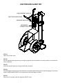
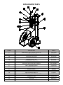
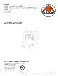
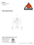
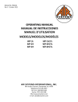
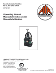
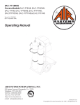
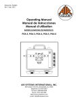
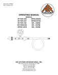
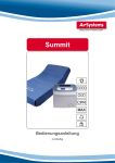
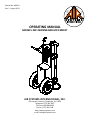
Manual No. PAK014
Rev. 2 August 2013
OPERATING MANUAL
MODELS: MP-2300ENB AND MP-2300ECY
Air Systems International, Inc.
829 Juniper Crescent, Chesapeake, Va, 23320
Telephone (757) 424-3967
Toll Free 1-800-866-8100
Fax No. (757) 424-5348
http://www.airsystems.com
e-mail: [email protected]
SPECIFICATIONS
Dimensions
Weight (w/o cylinders)
Frame
Cylinder Straps
Whip Assemblies
Check Valves
Low Pressure Whistle
Pressure Regulator
Relief Valve
Intrinsically Safe
Cylinders
48”H x 25”W x 31”D
120 lbs.
Powder Coated Steel
Four Adjustable Nylon Straps
5000 PSI Rated Thermo-Plastic Hose with a 4:1
Safety Factor
Stainless Steel, 1 per Whip Assembly
Set @ approximately 500 PSI
5500 PSI Max. Inlet Pressure
125 PSI Max. Outlet Pressure
ASME, preset @ 125 PSI
Yes, no electronic devices
(2) 444 cu. ft. 4500 PSI cylinders (P/N AC-444)
included with Model MP-2300ECY only!
SET-UP/OPERATION
CGA-346/347 HAND-TIGHT
BLEEDER VALVE
LOW PRESSURE WHISTLE
PRESSURE REGULATOR
RESPIRATOR
CONNECTIONS
STEP 1)
Place cylinders on cart and secure by tightening straps at the buckle. Mate the hook and loop sections to prevent
slipping.
STEP 2)
Install the CGA-346/347 universal hand-tight nuts to the cylinder valves and tighten. Close the bleeder valves by
turning knobs clockwise.
STEP 3)
Open cylinder valve(s). Whistle will sound until approximately 1000 PSI.
STEP 4)
Adjust regulator to desired output pressure by turning regulator knob clockwise to increase pressure or counterclockwise to decrease.
STEP 5)
Connect hose(s) and respirator(s) to the respirator connections.
STEP 6)
Readjust pressure regulator if necessary.
Note: The whip assemblies are equipped with check valves that prevent backflow from the opposing cylinder.
This also allows a cylinder to be replaced while the other cylinder is in use so workers can continue their
duties uninterrupted.
LOW PRESSURE ALARM TEST
LOW PRESSURE WHISTLE
INLET PRESSURE GAUGE
PRESSURE REGULATOR
RESPIRATOR
CONNECTIONS
STEP 1)
Open one cylinder valve.
STEP 2)
Set the required outlet pressure by turning the regulator knob clockwise to increase pressure or counterclockwise to decrease.
STEP 3)
Close the cylinder valve by turning the knob fully clockwise.
STEP 4)
Partially engage a plug into one of the respirator connections while viewing the inlet pressure gauge. As pressure
drops to approximatley 500 PSI, the low pressure whistle will begin to sound.
STEP 5)
When test is complete, open the regulator ON/OFF valve.
REPLACEMENT PARTS
ITEM #
1
2
2A
3
3A
4
5
6
7
8
9
10
11
12
13
14
DESCRIPTION
ASME RELIEF VALVE PRESET @ 125 PSI
HANSEN COUPLING
SCHRADER COUPLING
HANSEN DUST CAP
SCHRADER DUST CAP
OUTLET PRESSURE GAUGE
PRESSURE REGULATOR, NO GAUGES
INLET PRESSURE GAUGE
CHECK VALVE
BLEEDER VALVE
CGA-346/347 HAND-TIGHT
LOW PRESSURE WHISTLE
WHIP ASSEMBLY, 1/4” MPT X 1/4” FPT
CYLINDER STRAP
PULL PIN
16” PNEUMATIC WHEEL
PART #
VR4125BR
QDH3SL4M
QDSSL4M
QDH3DCAP
QDSDCAP
GA20160B
REG-5000NG
GA2075KB
VC4SMMSS
VAL030
SS347HT
AC-PA25
MP-23WHIP
HDWR113B
HDWR114
HDWR120
NOTES:
WArrAnty DiSclAimer
Air Systems’ manufactured equipment is warranted to the original user against defects in workmanship or materials under normal use for one year from the date of purchase. Any part which is determined by Air Systems
to be defective in material or workmanship will be, as the exclusive remedy, repaired or replaced at Air Systems’ option. This warranty does not apply to electrical systems or electronic components. Electrical parts are
warranted, to the original user, for 90 days from the date of sale. During the warranty period, electrical components will be repaired or replaced at Air Systems’ option.
no otHer WArrAnty, eXPreSSeD or imPlieD, AS to DeScriPtion, QUAlity, mercHAntABility, FitneSS
For A PArticUlAr PUrPoSe, or Any otHer mAtter iS GiVen By Air SyStemS in connection HereWitH. UnDer no circUmStAnceS SHAll tHe Seller Be liABle For loSS oF ProFitS, Any otHer Direct
or inDirect coStS, eXPenSeS, loSSeS, or DAmAGeS AriSinG oUt oF DeFectS in, or FAilUre oF tHe
ProDUct or Any PArt tHereoF.
The purchaser shall be solely responsible for compliance with all applicable Federal, State and Local OSHA and/
or MSHA requirements. Although Air Systems International believes that its
products, if operated and maintained as shipped from the factory and in accordance with our “operations
manual”, conform to OSHA and/or MSHA requirements, there are no implied or expressed warranties of such
compliance extending beyond the limited warranty described herein. Product designs and specifications are
subject to change without notice. rev. 2, 12/98
Air leaks are not covered under warranty except when they result from a defective system component, i.e. an
on/off valve or regulator or upon initial delivery due to poor workmanship. Air leaks due to poor delivery or
damage will be covered under delivery claims. Minor air leaks are part of routine service and maintenance and
are the responsibility of the customer just as are filters and oil changes.
Air SyStemS internAtionAl, inc.
829 Juniper Crescent, Chesapeake, Va, 23320
Telephone (757) 424-3967
Toll Free 1-800-866-8100
Fax No. (757) 424-5348
http://www.airsystems.com
e-mail: [email protected]
Printed in the U.S.A. ©Copyright Air Systems International, Inc. 2013 All Rights Reserved