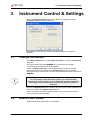
1
TECAN
Instructions for Use for
magellan
Document Part No.: 30019874
2006-01
Document Revision No.: 1.0
Software Revisions:
magellan Standard: 6.0
magellan Tracker: 6.0
TECAN
Tecan Affiliates and Service Centers
Austria
Tecan Austria GmbH
Untersbergstrasse 1a
A-5082 Grödig/Salzburg
Austria
Austria
Tecan Sales International GmbH
Untersbergstrasse 1a
A-5082 Grödig/Salzburg
Austria
T +43 6246 8933 256
F +43 6246 72 770
[email protected]
Tel.: +43 6246 8933
Fax: +43 6246 72 770
Belgium
Tecan Benelux bvba
Vaartdijk 55
B-2800 Mechelen
Belgium
China
Tecan Group Ltd, Beijing
Representative Office
Room 2502, Building A
Jianwai SOHO
No. 39 Dongsanhuan Zhong Rd.
100022 Beijing
China
T +32 15 42 13 19
F +32 15 42 16 12
[email protected]
Asia
Tecan Asia Pte Ltd.
80 Marine Parade
#10-09 Parkway Parade
Singapore 449269
Singapore
T +65 6444 1886
F +65 6444 1836
[email protected]
France
Tecan France SAS
26 avenue Tony Garnier
F-69007 Lyon
France
T +33 820 88 77 36
F +33 472 76 04 99
[email protected]
T +86 10 5869 5936
F +86 10 5869 5935
Germany
Tecan Deutschland GmbH
Theodor-Storm-Strasse 17
D-74564 Crailsheim
Germany
Italy
Tecan Italia S.r.l.
Via F.lli Cervi
Palazzo Bernini
Centro Direzionale Milano 2
I-20090 Segrate (Mi)
Italy
Japan
Tecan Japan Co., Ltd.
Kawasaki Tech Center
580-16, Horikawa-cho,
Saiwai-ku
Kawasaki, Kanagawa 212-0013
Japan
T +39 02 215 21 28
F +39 02 215 97 441
[email protected]
T +81 44 556 7311 (Kawasaki)
F +81 44 556 7312 (Kawasaki)
T +81 66 305 8511 (Osaka)
[email protected]
Netherlands
Tecan Benelux bvba
Industrieweg 30
NL-4283 GZ Giessen
Netherlands
Scandinavia
Tecan Nordic AB
Taljegårdsgatan 1
SE-431 53 Mölndal
Sweden
Spain (Barcelona)
Tecan Ibérica
Sabino de Arana 32
E-08028 Barcelona
Spain
T +31 183 44 81 74
F +31 183 44 80 67
[email protected]
T +46 317 54 40 00
F +46 317 54 40 10
[email protected]
T +34 93 490 0174
T +34 93 409 1237 (Helpdesk)
F +34 93 411 2407
[email protected]
Spain (Madrid)
Tecan Ibérica
Portugal
Tecan Ibérica
Quinta da Fonte Edificio Pedro I
P-2780-730 Paço D'Arcos
Portugal
Switzerland
Tecan Schweiz AG
Seestrasse 103
CH-8708 Männedorf
Switzerland
T +34 91 151 7107
T +34 93 409 1237 (Helpdesk)
F +34 91 151 7120
[email protected]
T +35 21 000 8216
T +41 44 922 82 82
F +41 44 922 84 84
[email protected]
United Kingdom
Tecan UK
Theale Court
11-13 High Street
Theale
UK-Reading RG7 5AH
United Kingdom
USA
Tecan US
4022 Stirrup Creek Road
Suite 310
Durham, NC 27703
USA
USA
Tecan Systems Inc.
2450 Zanker Road
San Jose, CA 95131
USA
T +49 1805 8322 633 or
T +49 1805 TECANDE
F +49 7951 9417 92
[email protected]
Gobelas 17 bjo. Izq. Urb. La Florida
E-28023 Madrid
Spain
T +44 118 930 0300
F +44 118 930 5671
[email protected]
2
T +1 919 361 5200
F +1 919 361 5201
Toll Free US:
T +1 800 TECAN US or
T +1 800 832 2687
[email protected]
T +1 408 953 3100
F +1 408 953 3101
Toll Free US/Canada:
T +1 866 798 3226
[email protected]
Instructions for Use for magellan No. 30019874 Rev No. 1.0
2006-01
TECAN
WARNING
CAREFULLY READ AND FOLLOW THE INSTRUCTIONS PROVIDED IN
THIS MANUAL BEFORE OPERATING THE INSTRUMENT.
Notice
Every effort has been made to avoid errors in text and diagrams, however, Tecan
Austria GmbH assumes no responsibility for any errors which may appear in this
publication.
It is the policy of Tecan Austria GmbH to improve products as new techniques
and components become available. Tecan Austria GmbH therefore reserves
the right to change specifications at any time.
We would appreciate any comments on this publication.
Tecan Austria GmbH
Untersbergstraße 1A
A-5082 Grödig/Salzburg
AUSTRIA/EUROPE
Telephone: +43 6246/8933
FAX: +43 6246/72770
E-mail: [email protected]
Copyright Information
The contents of this manual are the property of Tecan Austria GmbH and are not
to be copied, reproduced or transferred to another person or persons without our
prior written permission.
Copyright © Tecan Austria GmbH
All rights reserved.
Printed in Austria.
About this Manual
magellan is a universal data reduction package used to analyze data generated
from microplate assays for general research and in vitro diagnostic applications. It
is designed for professional use only.
This manual instructs how to:
•
•
2006-01
Install the software
Operate the software
Instructions for Use for magellan No. 30019874 Rev No. 1.0
3
TECAN
Warnings, Cautions and Notes
The following types of notices are used in this publication and highlight important
information or warn the user of a potentially dangerous situation:
Note
Gives helpful information.
Caution
Indicates a possibility of instrument damage or data loss if instructions
are not followed.
WARNING
INDICATES THE POSSIBILITY OF SEVERE PERSONAL INJURY, LOSS OF
LIFE OR EQUIPMENT DAMAGE IF THE INSTRUCTIONS ARE NOT
FOLLOWED.
4
Instructions for Use for magellan No. 30019874 Rev No. 1.0
2006-01
TECAN
Table of Contents
1.
Introduction
1.1
Area of Application.................................................................................................. 1-1
1.2
Intended Use of magellan ...................................................................................... 1-2
1.3
Specifications.......................................................................................................... 1-2
1.3.1
1.3.2
1.3.3
1.3.4
1.3.5
1.4
Software Installation Procedure.............................................................................. 1-4
1.4.1
1.4.2
1.4.3
2.
Automatic Software Setup Program ....................................................................... 1-4
Installation Qualification.......................................................................................... 1-5
Automatic Software Removal ................................................................................. 1-5
Start Working with magellan
2.1
User Interface ......................................................................................................... 2-1
2.1.1
2.1.2
2.1.3
2.1.4
2.1.5
2.2
2.3
Logging in for the First Time with magellan Tracker .............................................. 2-6
Change Password .................................................................................................. 2-7
Login ....................................................................................................................... 2-7
Application Locked.................................................................................................. 2-8
Licensing magellan ................................................................................................ 2-8
2.4.1
2.4.2
2.5
Demo Mode ............................................................................................................ 2-5
Starting magellan ................................................................................................... 2-6
2.3.1
2.3.2
2.3.3
2.3.4
2.4
Wizard List .............................................................................................................. 2-1
Standard Elements ................................................................................................. 2-3
The Help Button...................................................................................................... 2-4
The Welcome Dialog Box ....................................................................................... 2-4
Shortcuts List .......................................................................................................... 2-4
Connecting an Instrument....................................................................................... 2-5
2.2.1
Serial and License Number .................................................................................... 2-9
Registration Form ................................................................................................. 2-10
Quantitative ELISA Example ................................................................................ 2-12
2.5.1
2.5.2
2.5.3
2.5.4
3.
General ................................................................................................................... 1-2
Hardware Requirements......................................................................................... 1-2
Software Requirements .......................................................................................... 1-3
Reader Compatibility .............................................................................................. 1-3
CE Declaration for Europe...................................................................................... 1-4
Test Kit Description............................................................................................... 2-12
Create a Method ................................................................................................... 2-13
Run the Method .................................................................................................... 2-26
Evaluate the Result............................................................................................... 2-27
Instrument Control & Settings
3.1
3.2
3.3
3.4
3.5
2006-01
Change Instrument ................................................................................................. 3-1
Define Filter Slides.................................................................................................. 3-1
Insert Transport Lock.............................................................................................. 3-2
Optimize Z-Position ................................................................................................ 3-2
Plate Geometry Editor Wizard ................................................................................ 3-2
Instructions for Use for magellan No. 30019874 Rev No. 1.0
5
TECAN
3.6
3.7
3.8
3.9
3.10
3.11
4.
5.
Movements ..............................................................................................................3-2
Temperature Control ...............................................................................................3-3
Lamp/Laser Control .................................................................................................3-3
Injector Control ........................................................................................................3-3
Dispense Only .........................................................................................................3-3
Instrument Options ..................................................................................................3-3
Wizards
4.1
4.2
4.3
4.4
Method ....................................................................................................................4-1
Sample ID List .........................................................................................................4-1
Workspace ..............................................................................................................4-1
Standard Curve .......................................................................................................4-2
4.5
File Types Used with magellan...............................................................................4-2
Start Measurement Wizard
5.1
5.2
Introduction..............................................................................................................5-1
Obtain Raw Data .....................................................................................................5-2
5.2.1
5.3
5.4
5.5
5.6
5.7
6.
Run Strip Layout......................................................................................................5-4
Use Predefined Method...........................................................................................5-5
Start Favorite ...........................................................................................................5-6
Start Measurement ..................................................................................................5-7
Measurement Status .............................................................................................5-11
Evaluate Results Wizard
6.1
6.2
6.3
6.4
Introduction..............................................................................................................6-1
Select a File.............................................................................................................6-1
The Workspace Overview Window..........................................................................6-3
Evaluate Results Tab ..............................................................................................6-5
6.4.1
6.4.2
6.4.3
6.4.4
6.4.5
6.4.6
6.4.7
6.4.8
6.4.9
6.4.10
6.4.11
6.4.12
6.4.13
6.4.14
6.4.15
6.4.16
6.4.17
6
Obtain Raw Data with the Infinite Instrument ......................................................... 5-3
Menus ..................................................................................................................... 6-5
Toolbar Menu: File .................................................................................................. 6-6
Toolbar Menu: Edit................................................................................................ 6-11
Toolbar Menu: Instrument..................................................................................... 6-12
Plate Layout Window ............................................................................................ 6-12
Control Bar: Instrument Data ................................................................................ 6-13
Control Bar: Reduced Data................................................................................... 6-13
Control Bar: Transformed Data............................................................................. 6-13
Control Bar: Kinetic Parameters ........................................................................... 6-14
Control Bar: Concentrations ................................................................................. 6-15
Control Bar: Qualitative Results ........................................................................... 6-19
Control Bar: Sample IDs ....................................................................................... 6-19
Control Bar: Method Layout.................................................................................. 6-19
Control Bar: QC Validation ................................................................................... 6-19
Control Bar: Miscellaneous................................................................................... 6-20
Color Scale Dialog Box......................................................................................... 6-20
Context-Sensitive Menu of a Well ........................................................................ 6-20
Instructions for Use for magellan No. 30019874 Rev No. 1.0
2006-01
TECAN
6.5
6.6
7.
Attach Signature Wizard
7.1
7.2
8.
Introduction ............................................................................................................. 7-1
Sign a File............................................................................................................... 7-1
Create/Edit a Sample ID List Wizard
8.1
8.2
8.3
8.4
8.5
8.6
9.
Edit Method Tab ................................................................................................... 6-26
Saving the Evaluated Results............................................................................... 6-26
Introduction ............................................................................................................. 8-1
Create/Edit a Sample ID List .................................................................................. 8-1
Select Plate Type.................................................................................................... 8-2
Import/Edit a Sample ID List ................................................................................... 8-4
Import a Sample ID List .......................................................................................... 8-9
Saving the Sample ID List .................................................................................... 8-18
Create/Edit a Method Wizard
9.1
9.2
9.3
9.4
Introduction ............................................................................................................. 9-1
Creating or Editing Methods ................................................................................... 9-1
Define the Measurement Parameters..................................................................... 9-3
Define Evaluation.................................................................................................... 9-6
9.4.1
9.4.2
9.5
Precalculation ....................................................................................................... 9-18
9.5.1
9.5.2
9.5.3
9.6
Kinetic Data Reduction ......................................................................................... 9-27
Kinetics Transformations ...................................................................................... 9-30
9.8.1
9.9
Add New Transformation ...................................................................................... 9-24
Kinetic ................................................................................................................... 9-27
9.7.1
9.8
Precalculation – Polarization Data Reduction ...................................................... 9-18
Precalculation – Fluorescence Lifetime................................................................ 9-19
Precalculation – Spectra Data Reduction............................................................. 9-20
Transformed Data................................................................................................. 9-24
9.6.1
9.7
Method Layout – Plate Layout.............................................................................. 9-10
Method Layout – Conc., Dil. and Ref. Values....................................................... 9-14
Add New Kinetics Transformations ...................................................................... 9-30
Concentrations...................................................................................................... 9-31
9.9.1
Standard Curve..................................................................................................... 9-31
9.10 Evaluate Data ....................................................................................................... 9-36
9.10.1
9.10.2
Cutoff Definition .................................................................................................... 9-36
QC Validation ....................................................................................................... 9-37
9.11 Data Handling ....................................................................................................... 9-39
9.11.1
9.11.2
9.11.3
Data Export........................................................................................................... 9-39
Printed Report ...................................................................................................... 9-42
Automated Data Handling .................................................................................... 9-47
9.12 Miscellaneous ....................................................................................................... 9-49
9.12.1
9.12.2
9.12.3
User Prompts........................................................................................................ 9-49
Number Format .................................................................................................... 9-49
Method Notes ....................................................................................................... 9-49
9.13 Saving the Method................................................................................................ 9-50
9.14 Multiplate Methods................................................................................................ 9-51
2006-01
Instructions for Use for magellan No. 30019874 Rev No. 1.0
7
TECAN
10. Miscellaneous
10.1 Instrument Control .................................................................................................10-1
10.2 File Handling .........................................................................................................10-1
10.2.1
10.2.2
10.2.3
10.2.4
Archive Files ......................................................................................................... 10-1
Import Raw Data................................................................................................... 10-2
Convert To ............................................................................................................ 10-3
Convert From........................................................................................................ 10-4
10.3 Options ..................................................................................................................10-6
10.3.1
10.3.2
10.3.3
10.3.4
Default Data Paths................................................................................................ 10-7
Copy/ Export Options............................................................................................ 10-8
Plate View Settings............................................................................................. 10-10
Options – Miscellaneous..................................................................................... 10-11
10.4 User Administration (magellan Tracker) .............................................................10-13
10.4.1
10.4.2
10.4.3
10.4.4
10.4.5
10.4.6
Add/Modify User ................................................................................................. 10-14
Add/Modify Group............................................................................................... 10-15
User Administration Audit Trail ........................................................................... 10-15
User Rights ......................................................................................................... 10-16
User Administration Options ............................................................................... 10-20
User Administration Summary............................................................................ 10-22
10.5 User Administration (magellan Standard)...........................................................10-23
10.5.1
10.5.2
10.5.3
Add/Modify User ................................................................................................. 10-24
Login ................................................................................................................... 10-24
Change User....................................................................................................... 10-24
10.6 About magellan...................................................................................................10-25
11. Calculations
11.1 Evaluate Results - Calculation Procedure .............................................................11-1
11.2 Polarization Data Reduction ..................................................................................11-2
11.3 FLT Data Reduction ..............................................................................................11-4
11.3.1
Introduction ........................................................................................................... 11-4
11.4 Spectra Data Reduction ........................................................................................11-6
11.5 How to Write a Formula.........................................................................................11-7
11.5.1
11.5.2
11.5.3
11.5.4
11.5.5
11.5.6
11.5.7
11.5.8
11.5.9
11.5.10
Introduction ........................................................................................................... 11-7
Formula Variables................................................................................................. 11-7
Formula Operators................................................................................................ 11-7
Formula Functions ................................................................................................ 11-8
Basic Functions .................................................................................................... 11-9
Statistical Functions............................................................................................ 11-10
Elimination Functions.......................................................................................... 11-12
Other Functions .................................................................................................. 11-14
Spectra Functions............................................................................................... 11-14
Examples ........................................................................................................... 11-15
11.6 Standard Curve Analysis Types ..........................................................................11-17
8
Instructions for Use for magellan No. 30019874 Rev No. 1.0
2006-01
TECAN
12. Application Examples
12.1 Qualitative ELISA.................................................................................................. 12-1
12.1.1
Qualitative ELISA in magellan ........................................................................... 12-1
12.2 Quantitative ELISA ............................................................................................... 12-2
12.2.1
Quantitative ELISA in magellan ......................................................................... 12-3
12.3 Ion Channel Assay Development Using Voltage Sensor Probes (VSP)............... 12-4
12.3.1
The magellan Method ........................................................................................ 12-5
13. Glossary of Terms
Index
2006-01
Instructions for Use for magellan No. 30019874 Rev No. 1.0
9
TECAN
1. Introduction
1.
Introduction
1.1
Area of Application
magellan is a universal reader control and data reduction software for
analyzing data generated from microplate tests using Tecan measuring devices.
magellan is available in two versions:
•
magellan Tracker and
magellan Standard.
•
magellan Standard software is intended for endpoint, kinetic and multilabel
assays in pharmaceutical, biotechnological and life science industry, for research
use, for food analysis and veterinary applications.
magellan Tracker offers all functionality to become compliant with the FDA rule
21 CFR part 11.
Note
It is important to note that the proper installation of the instrument and
the magellan software alone will not ensure compliance with all regional
and national laws and requirements. Corresponding policies concerning
processes and standard operating procedures, including validation and
quality control, must also be established.
When using magellan Tracker, a user administration system must be installed
by a designated administrator, who is responsible for the setup of user accounts
and for the assignment of user rights.
Three default levels of user rights can be selected: Administrator,
Application Specialist and Operator. The administrator must always be trained
by Tecan or a Tecan authorized organization.
1. The Administrator must be trained as laboratory supervisor and is
responsible for procedural and technical laboratory issues and
compliance with federal regulations.
magellan allows the administrator to:
•
Change general software and instrument settings.
•
Define specifications containing measurement parameters and
evaluation settings and carry out measurements accordingly.
2. The Application Specialist must be trained as laboratory technician and
is responsible for performance of routine tests and examinations and
assistance in the setup of experiments. magellan allows the application
specialist to define specifications containing measurement parameters
and evaluation settings and carry out measurements accordingly. The
application specialist must be trained by the administrator.
3. The Operator must be trained as laboratory assistant and performs
routine analysis under immediate supervision. magellan allows the
operator to carry out measurements according to the specifications given
by the application specialist or administrator. The operator cannot
change those specifications. The operator must be trained by the
administrator.
2006-01
Instructions for Use for magellan No. 30019874 Rev No. 1.0
1-1
TECAN
1. Introduction
magellan Tracker is designed for use with the operating systems and Microsoft
Office versions specified in chapter 1.3.3 Software Requirements. If additional
programs are installed, functionality in accordance with IVD for Europe and FDA
regulations cannot be guaranteed.
magellan is designed to be used with one computer; it is not intended to be
integrated into a network.
1.2
Intended Use of magellan
magellan software is a reader control and data reduction software for analyzing
data generated from microplates using a Tecan absorbance, fluorescence and/ or
luminescence microplate reader. magellan software is intended for professional
use according to the software specifications described in this manual. magellan
software is available in tow different versions:
•
magellan Standard software is intended for endpoint, kinetic and multilabel
assays in pharmaceutical, biotechnological and life science industry, for
research use, for food analysis and veterinary applications.
•
magellan Tracker software is based on magellan Standard software,
intended for use in FDA 21 CFR part 11 regulated environments. It offers all
functionality to become compliant with the FDA rule 21 CFR part 11. The
rule states the conditions under which the FDA considers electronic records
and electronic signatures to be trustworthy, reliable and equivalent to
traditional handwritten signature on paper.
1.3
Specifications
1.3.1
General
The magellan software is available in 2 different versions:
•
magellan Standard software is the basic version and supports only a basic
user administration.
•
magellan Tracker software offers the same functionality as magellan
Standard, but additionally provides an advanced user administration with
customizable user rights and the possibility to sign methods and
workspaces. The saving of all measured data is automatic and all results are
traceable through the user administration / audit trail.
1.3.2
Hardware Requirements
The following requirements have to be met for using magellan:
Hardware
Minimum
Recommended
Advanced (FLT/Scanning)
Memory
256 MB
512 MB
1024 MB
CPU
Pentium II
Pentium III
Pentium IV
Resolution
1024 x 768 dpi
1280 x 1024 dpi
1280 x 1024 dpi
Serial/ USB ports
1
2
2
When an Infinite instrument is connected, we recommend at least 512 MB
memory and Pentium III.
1-2
Instructions for Use for magellan No. 30019874 Rev No. 1.0
2006-01
TECAN
1.3.3
1. Introduction
Software Requirements
The following requirements have to be met for using magellan:
Operating system
Microsoft Windows™
Windows XP Professional/SP2
Additionally supported software: Microsoft Excel 2000, Microsoft Excel XP,
Microsoft Excel 2003
1.3.4
Reader Compatibility
The following Tecan readers can be used with magellan:
Instrument Types
Measurement Mode
DNA Expert
Fluorescence / Absorbance / Luminescence
FARCyte
Fluorescence / Luminescence / Polarization
GENios
Fluorescence / Absorbance / Luminescence
GENios FL
Fluorescence / Luminescence
GENios Plus
Fluorescence / Absorbance / Luminescence
GENios Pro
Fluorescence / Absorbance / Luminescence / Polarization
SPECTRAFluor
Fluorescence / Absorbance
SPECTRAFluor Plus
Fluorescence / Absorbance / Luminescence
SAFIRE
Fluorescence / Absorbance
SAFIRE2
Fluorescence / Absorbance / Luminescence / Polarization
SUNRISE
Absorbance
ULTRA Evolution
Fluorescence / Absorbance / Luminescence / Polarization / FLT
ULTRA
Fluorescence / Absorbance / Luminescence / Polarization
ULTRA 384
Fluorescence / Absorbance / Luminescence / Polarization
Infinite M200
Fluorescence / Absorbance / Luminescence / Polarization
Infinite F200
Fluorescence / Absorbance / Luminescence / Polarization
Note
The Connect stacker can be used together with several instruments in
order to measure batches of plates. Please refer to the Connect
Instructions for Use for more information.
™
Windows and Excel are registered trademarks of the Microsoft Corporation
2006-01
Instructions for Use for magellan No. 30019874 Rev No. 1.0
1-3
TECAN
1. Introduction
1.3.5
CE Declaration for Europe
The following CE declarations for Europe are available with magellan:
magellan Versions
CE Declaration for Europe
magellan Standard
CE Declaration for Europe does not exist or it is unrelated to IVD
compliance for Europe
magellan Tracker
CE Declaration for Europe does not exist or it is unrelated to IVD
compliance for Europe
1.4
Software Installation Procedure
1.4.1
Automatic Software Setup Program
magellan is installed by an automatic software setup program. All necessary
components are installed automatically.
Start Setup.exe to begin the installation procedure. Some components of this
software are using the Microsoft .NET Framework technology. Click I agree in the
window which appears immediately after having started the setup to continue.
The setup program then starts inspecting your current configuration, this may
take some seconds.
A welcome window appears with information about the software and the
installation process. Click Next to continue.
The next window displays the License Agreement. Read the License
Agreement and click I agree to accept it and continue.
In the next window the user has to decide whether to install a new version from
scratch or to perform an update or repair. Select according to your needs and
click Next.
The Choose Destination Location window appears next. The default installation
path is displayed. Click Browse to change the default destination path, if desired.
Click Next to continue.
In the next window, a name for the program group, in which the program will be
stored, can be entered or chosen from the list. The default group name is Tecan.
Click Next to continue.
The serial number window appears next. If you have already purchased the
software enter now your serial number and click Next. If you do not yet have a
serial number click Next as well to continue the setup. You can register later (see
chapter 2.4 Licensing magellan).
1-4
Instructions for Use for magellan No. 30019874 Rev No. 1.0
2006-01
TECAN
1. Introduction
In the next window, select magellan Standard or magellan Tracker, depending
on which version you have ordered, to install the software. Click Next to continue.
Example files will be installed with the setup if in the next window this option is
selected. At a later moment, additional language versions might be available; in
the current window the language version can then be selected from a drop down
list.
The setup program is now ready for installation. Click Next to start installation.
The setup program automatically detects a previous installation of magellan. You
have the possibility to reuse existing data files or make a new installation (existing
files will be moved to a backup folder). Click OK to confirm.
Click Finish to end installation and close the setup program.
The software can be started via the Windows Start menu by selecting magellan6
in the program group defined above.
Note
It is very important that the person who installs the software has
administrator rights on the computer.
1.4.2
Installation Qualification
It is recommended to check successful installation of magellan with the
automatic installation qualification program.
Start MagellanIQ.exe from the default installation path specified in the setup
program (typically C:\Program Files\Tecan\Magellan) or from the Windows Start
menu: Start > Programs > Tecan > MagellanIQ.
The installation qualification program automatically detects the installed version of
magellan. Click Check to start the installation qualification. This may take some
minutes.
A detailed report shows the summary of all installed components. All report items
should have status OK. Please contact your local dealer if any potential problem
is reported. The report can be copied to clipboard for further printout or
attachment to your email.
You can leave the installation qualification program by clicking Cancel and Exit.
Note
The installation qualification should be repeated each time new software
is installed.
1.4.3
Automatic Software Removal
The magellan software can be removed using the standard Windows uninstall
routine:
magellan must be closed.
Select Add/Remove Programs from the Settings - Control Panel in the
Windows Start menu.
Select the magellan icon and click Remove.
The Uninstall wizard is started. Select the preferred uninstall method (Automatic
or Custom) and click Next to continue.
2006-01
Instructions for Use for magellan No. 30019874 Rev No. 1.0
1-5
TECAN
1. Introduction
In the next window, click Finish to uninstall magellan.
In the next window, decide whether or not shared components should be
removed. If Yes is selected, magellan will be completely uninstalled and other
Tecan programs such as XFluor, HS Control Manager or Gemini will no longer
work. Leaving these components installed will not harm your system. If you are
not sure what to do, it is suggested that you choose to not remove the shared
components. After clicking Yes or No, the magellan software is uninstalled.
Note
When removing all shared components, the user administration data is
also removed. Some Tecan program, for example XFluor, will no longer
function and must be reinstalled.
1-6
Instructions for Use for magellan No. 30019874 Rev No. 1.0
2006-01
TECAN
2. Start Working with magellan
2.
Start Working with magellan
2.1
User Interface
The main type of the user interface in magellan is the wizard.
Standard magellan wizards represent workflow modules, which are step-by-step
guides for performing complex procedures.
For a detailed step-by-step example which shows how to use the basic wizards,
please refer to chapter 2.5 Quantitative ELISA Example.
The Wizards simplify the performing of procedures by providing standard
workflows, which represent typical processes used in hospitals and laboratories,
thus reducing required training and preventing user errors.
Occasionally menus are available in the heading bar.
The Menu offers a conventional way of using the software: the relevant menu
item is selected from the main menus. All subsequent actions are started
instantly, or a dialog box is displayed where further selections or entries can be
made.
2.1.1
Wizard List
After launching magellan the wizard list is displayed:
The Attach signature wizard is only available with magellan Tracker.
The wizard list contains the following icons:
2006-01
Change current user
Temperature control
Miscellaneous
Move plate
Instructions for Use for magellan No. 30019874 Rev No. 1.0
2-1
TECAN
2. Start Working with magellan
Click on the Miscellaneous icon to select the following options:
Instrument control
Options
File handling
User administration
About magellan
The following wizards can be accessed from the Wizard List window:
1. Wizards
Double-click Start measurement or select Start measurement and click
to start the Measurement wizard, in which the following choices are
Next
available (see chapter 5 Start Measurement Wizard):
a. Obtain Raw Data is used to generate raw data quickly and easily by
setting the required measurement parameters and starting a measurement.
The Obtain raw data wizard creates a new workspace in which the
obtained values are presented and stored.
b. Run Strip Layout is used to collect strips from different methods.
c. Use Predefined Method is used to perform measurements based on
previously defined methods. The wizard creates a new workspace
containing the selected method (which consists of all measurement
parameters and evaluation definitions) and enables you to insert a sample
ID list. After the measurement, the workspace is completed with the
obtained raw data that will be evaluated.
d. Start Favorite is used to select one of the most frequently used methods
from the list of numbered icons.
Double-click Evaluate results or select Evaluate results and click Next
to
start the Evaluate Results wizard, which is used to view the raw data and to
evaluate the results. The evaluation parameters can be viewed and data can be
re-evaluated (see chapter 6 Evaluate Results Wizard).
Double-click Attach signature or select Attach signature and click Next
to
start the Attach Signature wizard, which is used to sign method and workplace
files. This feature is only available with magellan Tracker. Signatures are always
included in the printed report. Signed records can only be modified by users with
the appropriate rights. It is possible to fully control the use of methods by allowing
users to run only signed methods (see chapter 7 Attach Signature Wizard ).
Double-click Create/ edit a sample ID list or select Create/ edit a sample ID list
and click Next
to start the Create/Edit a Sample ID list wizard, which is
used to create new sample ID lists. Up to three sample IDs per well can be
entered or imported (see chapter 8 Create/Edit a Sample ID List Wizard).
Double-click Create/ edit a method or select Create/ edit a method and click
Next
to start the Create/Edit a Method wizard, which is used to define
methods. Methods include all necessary parameters for measurement,
evaluation, and data handling according to the performed assay (see chapter
9 Create/Edit a Method Wizard).
2-2
Instructions for Use for magellan No. 30019874 Rev No. 1.0
2006-01
TECAN
2. Start Working with magellan
2. Miscellaneous
This button takes you to the following options:
a. Instrument control provides quick access to several instrument functions
and service and setup options. See chapter 3 Instrument Control &
Settings.
b File handling is used to move files to an archive location. See chapter
10.2 File Handling.
c. Options is used to customize certain default settings as path of generated
files, clipboard and Excel copy options, the plate view and miscellaneous
wizard, startup, language and password settings. See chapter
10.3 Options.
d. User administration is used to add/ remove users and create/ modify user
rights. See chapter 10.4 User Administration (magellan Tracker),
respectively 10.5 User Administration (magellan Standard).
e. About magellan provides license information and details on the currently
installed version and components. Registration can be requested starting
the Register wizard (see chapter 2.4 Serial and License Number).
Close the Miscellaneous window to go back to the wizard list.
2.1.2
Standard Elements
Each wizard consists of a number of windows that are displayed sequentially.
All necessary information, settings and data entry possibilities are provided.
Standard Elements of a Magellan Wizard
For navigation from one window to another there are several buttons at the
bottom of the wizard page. The following buttons are used in the individual
windows of a wizard:
2006-01
Back button
The Back button is used to navigate back to the previous
window within a wizard.
When the window is the active area click <<< Back or press
SHIFT+B to navigate back to the previous window.
Next button
The Next button is the large green arrow in the bottom right
corner and is used to navigate forward to the next window
within a wizard.
When the window is the active area click Next or press
SHIFT+N or ENTER to navigate forward to the next window.
Finish button
The Finish button is only found in the last window of a wizard
and replaces the Next button. The Finish button is a large
green arrow in the bottom right corner. It is used to close the
wizard and save all changes or to start a process.
When the window is the active area click Finish or press
ENTER to close a wizard and to save all changes.
Cancel button
The Cancel button is used to close a wizard without saving any
changes to settings or documents.
When the window is the active area click Cancel or press ESC
to close a wizard without saving any changes.
Help button
The Help button opens the help window.
When the window is the active area click Help or press F1 to
open the help window.
Instructions for Use for magellan No. 30019874 Rev No. 1.0
2-3
TECAN
2. Start Working with magellan
Standard Elements of Microsoft Windows™
OK button
This button confirms settings, applies and saves changes
accordingly and closes the dialog box.
Cancel button
This button closes the dialog box without saving any changes
to settings or documents.
Help button
Click the Help button to open the magellan online help.
Status Bar Information
The status bar displays the following information:
•
•
•
•
•
•
•
2.1.3
Current command info
User name of the currently logged in user.
Name of connected instrument. For example: Sunrise
Method: measurement mode and unit. For example: Absorbance [OD]
Workspace: date and time of measurement. For example: 27.11.2002
14:13:03
Number of selected wells. For example: 3 well(s) selected
Keyboard status information: activity of the keyboard toggles: CAP (caps
lock), NUM (Numeric block lock), SCRL (Scroll lock)
Instrument connection state icon
The Help Button
Click the Help button to open the magellan online help. The tabs Contents, Index
and Search are available. For further details on using the Windows™ Help
function refer to your Windows instructions of use.
2.1.4
The Welcome Dialog Box
Each wizard starts with a Welcome dialog box, which gives a short introductory
description of the procedure to be performed.
Clear the Show welcome page check box to suppress welcome pages when
starting wizards in the future.
2.1.5
Shortcuts List
SHIFT+B
Back button
SHIFT+N
Next button
ESC
Cancel button
ENTER
Next or Finish button, if active window
F1
Help menu
SHIFT+F1
Context Help menu
CTRL+C or CTRL+INSERT
Copy
CTRL+V or SHIFT+INSERT
Paste
CTRL+X
Cut
CTRL+Y
Redo
CTRL+Z
Undo
DEL
Delete content of active well (edit sample ID, edit formula)
CTRL+SHIFT
Show formula of selected well when transformation is viewed
(Evaluate Results wizard)
™ Windows is a registered trademark of the Microsoft Corporation
2-4
Instructions for Use for magellan No. 30019874 Rev No. 1.0
2006-01
TECAN
2.2
2. Start Working with magellan
Connecting an Instrument
Click the miscellaneous icon
in the wizard list and instrument control in
the miscellaneous list. The instrument control window is displayed showing two
group boxes: Instrument and Setup & Service. Select Change instrument from
setup & service to connect an instrument or to change the currently connected
instrument.
magellan can be run either with an instrument connected or in a demo mode,
simulating an instrument connected.
Connect the instrument to your computer as described in the instructions for use
for the instrument and switch on the instrument before starting magellan.
The first time magellan is started, the Setup Port dialog box appears :
2.2.1
Instrument
In the Instrument group box, select the connected
instrument from the drop down list or select Find any.
Port
Select the appropriate COM port from the drop down
list or select Find any. Click OK. The instrument is now
ready for operation using the magellan software.
Stacker Port
If a Tecan Connect stacker is used together with the
instrument, select the connecting port from the drop
down list or select Find any. If no stacker is used select
None for the stacker port.
Demo Mode
If no instrument is connected, select the instrument to be simulated from the drop
down list in the Instrument group box and select Demo mode in the Port group
box. Click OK. magellan is now in demo mode. Demo mode allowed (in the
Options dialog) is selected by default.
In demo mode it is possible to perform all functions except running actual
measurements (see chapter 10.3.4 Options – Miscellaneous to change this
default setting).
The Connect stacker can also be simulated in demo mode.
2006-01
Instructions for Use for magellan No. 30019874 Rev No. 1.0
2-5
TECAN
2. Start Working with magellan
2.3
Starting magellan
Perform the following steps to start magellan:
2.3.1
1.
2.
Make sure that an instrument is connected or that Demo mode is allowed.
In the Windows Start menu, select the Tecan program group and click the
magellan icon.
3.
If configured – in magellan Tracker it is mandatory !–, the Login dialog box
appears. Enter the Username and Password and click Login.
4.
magellan starts.
Logging in for the First Time with magellan Tracker
When magellan Tracker is started for the first time, a dialog box appears,
informing the user that a User Administrator must be created first. Click OK and
the Create Administrator dialog box appears.
Complete the text fields and click OK to save the settings. At least one user
administrator must be created.
Caution
If the User Administrator password is forgotten, User Administration
settings cannot be changed and magellan must be completely reinstalled.
Note
It is recommended that at least two User Administrators are created.
After clicking OK, the User Administration dialog box appears:
Users and groups can be added, edited, or deleted and user rights can be
defined. Options for login, password, and email can be edited.
2-6
Instructions for Use for magellan No. 30019874 Rev No. 1.0
2006-01
TECAN
2.3.2
2. Start Working with magellan
Change Password
Initial Password (magellan Tracker only)
When a user logs in for the first time, the password assigned by the administrator
has to be changed.
After entering the User name and Password and clicking OK, the message
“Your initial password is only valid once. You have to change the password!”
appears. Click OK; the Change Password window invites the user to enter a
new password.
Password Expiration (magellan Tracker only)
When the password expires, the user will be prompted to enter a new password.
The old password has to be entered. The new password must comply with the
defined password rules and has to be entered twice to prevent typing errors. Old
passwords cannot be reused. The new password will expire after a defined period
of time. See chapter 10.4.5 User Administration Options.
2.3.3
Login
Once user administration has been activated, each time magellan starts, the
Login dialog box will appear. The user account will be disabled after the
maximum number of consecutive unsuccessful logins has been reached (see
chapter 10.4.5 User Administration Options - Login Options).
The Login dialog box contains the following elements:
Username text box
Enter your UserID
Password text box
Enter your Password
Click the GO button to close the dialog box and the user is logged in. Only those
user actions can be performed, that correspond to the user's rights.
Click the Cancel button to close the dialog box and magellan is terminated.
2006-01
Instructions for Use for magellan No. 30019874 Rev No. 1.0
2-7
2. Start Working with magellan
2.3.4
TECAN
Application Locked
If the application has not been in use for the specified maximum of time (user
defined only in magellan Tracker) it will be locked. The password must be
entered to unlock the application.
2.4
Licensing magellan
The licensing of magellan is performed with the Register magellan wizard. If
magellan has not been registered, this wizard will launch automatically each time
the program is started. To start the Register magellan wizard, select Register
from the About magellan box (miscellaneous → About magellan → Register).
Note
The full version of magellan can be used unregistered for 30 days. If
magellan is not registered after this period, the save and print options
will be disabled.
Two scenarios are possible:
The software has been purchased. Together with the software the serial number
is delivered.
The software was delivered as a demo version together with the instrument.
In order to register magellan, a serial number and license number are required.
After the serial number and the license number have been entered, the Register
magellan wizard confirms the license number and summarizes the user
information. Click the Finish button to complete the registration procedure.
magellan’s functions will then remain fully available to the user.
Note
It is very important that the person who registers the software has
administrator rights on the computer with operating system Win XP.
The registration wizard starts with the Welcome dialog box, which contains a
short description of the wizard. Click Next and the Serial Number dialog box
appears.
2-8
Instructions for Use for magellan No. 30019874 Rev No. 1.0
2006-01
TECAN
2.4.1
2. Start Working with magellan
Serial and License Number
Select Enter your magellan serial number, if the magellan software has
already been purchased. Enter the serial number, which is found in the magellan
package.
If the magellan software has not yet been purchased, the second option, Order
magellan to obtain a valid license, must be selected. The Registration Form
window will then appear (see chapter 2.4.2 Registration Form).
After having entered the serial number, click Next and the License Number
dialog box appears.
Users installing the software for the first time will not yet have a license number
and must select Request a magellan license number because you did not
receive one. Click Next and the Registration Form window appears.
2006-01
Instructions for Use for magellan No. 30019874 Rev No. 1.0
2-9
2. Start Working with magellan
2.4.2
TECAN
Registration Form
Complete the registration form. Fields marked with an asterisk are mandatory.
Click Next and the license agreement window appears. Read it carefully and click
the I agree button.
Click Next and the registration information is displayed.
Click E-Mail Form… to send the information using the default e-mail program on
your computer or click Print Form… to print out the registration form for faxing or
mailing it to Tecan. Click View Form… to view the registration form using
WordPad or Notepad. Within 24 hours you will receive the license number.
2-10
Instructions for Use for magellan No. 30019874 Rev No. 1.0
2006-01
TECAN
2. Start Working with magellan
Click Next and the Registration requested window appears:
After having received the license number from Tecan, repeat the steps above and
insert the license number. Click Next. The registration wizard then confirms the
license number and summarizes the user information.
Click Finish; the Register magellan wizard will close and magellan’s functions
will remain fully available to the user.
2006-01
Instructions for Use for magellan No. 30019874 Rev No. 1.0
2-11
TECAN
2. Start Working with magellan
2.5
Quantitative ELISA Example
A step-by-step example (quantitative test) of how to create a method in magellan
is provided in this chapter. By following the instructions you will learn how to
define evaluations from a test kit description in magellan.
The method was created using a Sunrise in demo mode, but it is also possible to
define the methods with another Tecan instrument connected, if it is able to
measure absorbance.
2.5.1
Test Kit Description
In the manufacturer’s test kit description of a quantitative IgM - Antibody
detections - ELISA the following instructions are found: Plate Layout
1
2
3
A
BLK
C3
S1
B
NC
C4
S2
C
NC
C4
S2
D
C1
C5
S3
E
C1
C5
S3
F
C2
C6
…
G
C2
C6
…
H
C3
S1
4
5
6
7
8
9
10
11
12
BLK = Blank, NC = Negative control, C1 – C6 = Calibrators (Standards),
S1 – S… = Samples
Measurement and Evaluation
Read plate at a wavelength of 492nm, reference at 620nm.
Blank reader/plate on well A1.
Concentrations of the Calibrators (Standards):
Calibrator 1
5 UA/mL
Calibrator 2
10 UA/mL
Calibrator 3
20 UA/mL
Calibrator 4
40 UA/mL
Calibrator 5
80 UA/mL
Calibrator 6
160 UA/mL
After the blank correction the optical densities (OD492–OD620) are plotted
versus the concentration. The regression line that goes through these points is
the standard curve.
Interpretation of the test results:
IgM < 18 UA/mL
Negative
18 UA/mL <= IgM < 22 UA/mL
Intermediate
IgM >= 22 UA/mL
Positive
The calculated IgM concentration of both negative controls must be under
8 UA/mL.
2-12
Instructions for Use for magellan No. 30019874 Rev No. 1.0
2006-01
TECAN
2. Start Working with magellan
Data Handling
After the measurement, the data file (workspace) is stored automatically and a
report containing the measurement parameters, plate layout, blanked values,
standard curve, IgM-concentrations, cutoff definition, qualitative results of the
samples and validations is created.
Additionally, the layout and the qualitative results are be stored as ASCII file.
2.5.2
Create a Method
In the Wizard List dialog box, select Create/edit a method and click OK. Click
next on the Welcome page of the Create/edit a method wizard and the Select a
file dialog box appears. Select Create new.
Measurement Parameters
Click Next and the Measurement parameter dialog box appears.
2006-01
Instructions for Use for magellan No. 30019874 Rev No. 1.0
2-13
2. Start Working with magellan
TECAN
Select Endpoint measurement and click the Measurement parameters button.
The following dialog box appears:
On the General tab select Absorbance.
On the Wavelengths tab select 492nm as Measurement wavelength and
620nm as Reference wavelength.
Click OK to return to the Measurement parameter dialog box.
Click Define evaluation and the Plate layout window is displayed.
2-14
Instructions for Use for magellan No. 30019874 Rev No. 1.0
2006-01
TECAN
2. Start Working with magellan
Design Layout
Define the plate layout using the Well Assignment dialog box on the right side of
the screen.
In the Identifiers group box, select BL (Blank).
In the Experimental group box the number 1 remains.
In the Replicates group box, select All.
Click well A1, which is then marked with a red border.
Click Fill selection and the well is labeled with the selected identifier type.
Note
A single well can also be filled by double-clicking it.
Now choose the following settings in the Well Assignment dialog box:
In the Identifiers group box, select NC (Negative Control).
In the Experimental group box the number 1 remains.
All is selected in the Replicates group box.
Starting at well B1 click and drag the mouse to C1. The wells B1 to C1 are then
marked with a red border.
Click Fill selection and the wells are labeled with the selected identifier type.
Next, calibrators (standards) must be assigned to wells D1 to G2. Select the
following settings in the Well Assignment dialog box:
In the Identifiers group box, select ST (Standard).
In the Experimental group box the number 1 remains.
In the Replicates group box, choose between Fix number and All:
Fix number
Only enabled for standards and samples where IDs can be used.
If this Fix number button is active a number can be entered in the corresponding
text field. This number defines how many replicates are intended for this method.
In the selected wells, the entered number of replicates for every ID is created.
Therefore the number of selected wells must be a multiple of the entered number
of replicates.
2006-01
Instructions for Use for magellan No. 30019874 Rev No. 1.0
2-15
2. Start Working with magellan
TECAN
All
All selected wells are defined as replicates. If an existing ID number for the
samples and standards is chosen, the selected wells are then added as
replicates to the existing replicates. With all other identifier types the selected
wells are added as replicates to the existing replicates.
define the direction of the replicate and ID number
Two arrow buttons
sequence (horizontal or vertical).
In this example select Fix Number and 2.
In the ID-Number box and in the Replicates group box select the vertical
arrows.
Then select the wells D1 to G2 and click Fill selection.
Note
Select the wells as follows: Starting at well D1 click and drag the mouse
over the required wells to H1. Then hold down the control (Ctrl) key and
drag the mouse over the required wells from A2 to G2.
The Plate Layout appears as follows:
Click Select all unused from the toolbar to select all empty wells on the plate.
Then hold down the control (Ctrl) key and click the well H12, so that it remains
blank and unmarked.
In the Well Assignment dialog box select SM (Sample) under Identifiers.
In the Experimental group box the number 1 remains.
In the Replicates group box choose Fix number and 2.
2-16
Instructions for Use for magellan No. 30019874 Rev No. 1.0
2006-01
TECAN
2. Start Working with magellan
In the ID-Number box leave 1 and in the Replicates group box select the
vertical arrows. Click then Fill selection. The layout definition procedure is
complete.
Transformations
In the control bar on the left of the window select the next option, Add new
transformation… from the Transformed data item, to define blank reduction.
A dialog box appears asking you if you want to define a blank reduction. Click
Yes.
Select Difference Data in the Input data box. By default the transformation is
named Transformation1 (see control bar). If you have confirmed the definition of
a blank reduction before, the software automatically names it Blank reduction.
In the Formula box automatically appears x-BL1 for this blank reduction, where x
refers to the current input data value in a well and BL1 is the mean value of the
blank wells of experimental group 1.
Now select the whole plate by clicking the
sign in the upper left corner of the
microplate and click the green hook next to the formula window to assign the
transformations to the wells. Fur further details and explanations concerning the
definition and assignment of transformations, refer to chapter 9.6.1 Add New
Transformation. The following window appears.
2006-01
Instructions for Use for magellan No. 30019874 Rev No. 1.0
2-17
TECAN
2. Start Working with magellan
In each well the following information appears (example well A5):
SM1_9
Sample, experimental group number 1,
sample ID number 4.
2/2
Number of replicate is 2, total number of replicates is 2.
x-BL1 or 1.000
Assigned transformation x-BL1 (when Transformation is
selected) or Dilution Factor value of 1 (when Conc., Dil,.
Ref.-values is selected).
Concentration / Dilution / Reference Value Definition
In the control bar select Conc., Dil,. Ref.-values from the Method layout item to
define the respective values as described in the test kit.
Calibrator 1
5 UA/mL
Calibrator 2
10 UA/mL
Calibrator 3
20 UA/mL
Calibrator 4
40 UA/mL
Calibrator 5
80 UA/mL
Calibrator 6
160 UA/mL
Make sure ST is selected in the Select Identifier list .
In the Identifier list, a list of the standards from the Exp. Group 1 appears. In the
corresponding Concentration box of ST1_1 type the number 5 and in the Unit
box, type UA/mL. In the corresponding Concentration box of ST1_2 type the
number 10. The unit only needs to be defined once and is valid for all standards.
Type the values for the ST1_3 to ST1_6 in the same way.
The screen showing the plate layout and the concentration is displayed:
2-18
Instructions for Use for magellan No. 30019874 Rev No. 1.0
2006-01
TECAN
2. Start Working with magellan
Standard Curve
In the control bar click Standard curve from the Concentrations item to define
the appropriate standard curve.
The following is in the test kit description:
After the blank correction, the optical densities (OD 492 - OD 620) are plotted
versus the concentration. The regression line that goes through these points is
the standard curve.
On the Data tab, select Blank reduction as input data.
On the Analysis type tab, select Linear regression.
2006-01
Instructions for Use for magellan No. 30019874 Rev No. 1.0
2-19
2. Start Working with magellan
TECAN
On the Axis tab, define the labeling and the scaling of the axis as shown below:
On the Graph tab, define the graph title, curves, font and graph display.
2-20
Instructions for Use for magellan No. 30019874 Rev No. 1.0
2006-01
TECAN
2. Start Working with magellan
Define Cutoffs
In the control bar select Cutoff definition from the Evaluate data item to define
the limits for the qualitative evaluation.
The test kit description contains the following instructions:
Interpretation of the test results:
IgM < 18 UA/mL
Negative
18 UA/mL <= IgM < 22 UA/mL
Intermediate
IgM >= 22 UA/mL
Positive
Use the following procedure to define the appropriate cutoffs:
In the Input data box, select Mean conc. (UA/mL).
The Cutoffs table represents a scale indicating the high and the low end for the
Limits and Labels. In Limits, type 22 as the first (higher) limit and 18 as the
second (lower) limit.
In Labels, enter the test interpretation (Positive, Intermediate and Negative)
into the individual boxes. Use the drop down color palette to assign a color:
Positive – Red
Intermediate – Blue
Negative – Green
The screen contains the following:
Click Cutoff results selection to select the identifier types for which the cutoff
results must be shown.
2006-01
Instructions for Use for magellan No. 30019874 Rev No. 1.0
2-21
2. Start Working with magellan
TECAN
Define QC Validations
In the control bar, click QC Validations from the Evaluate data item. Validation
criteria for the test must be defined, so that the validity of the test results is
guaranteed.
In this example the following requirement must be fulfilled:
The calculated IgM-concentration of both negative controls must be under
8 UA/mL.
In the Input box, select Single conc. (UA/mL).
In the first row, type NC1_1<8, or enter the formula using the available variables,
operators and functions.
Note
NC1_1 means Negative control of experimental group 1, replicate 1.
In the second row, type NC1_2<8.
The QC Validations dialog box is now displayed as follows:
2-22
Instructions for Use for magellan No. 30019874 Rev No. 1.0
2006-01
TECAN
2. Start Working with magellan
Organize Printed Report
In the control bar, click Printed report from the Data handling item. The
following screen is displayed:
On the Data selection tab, all available report data is contained in the Available
data box. Using the Insert and Append buttons, data can be transferred into the
Selected data box. Data can also be transferred using drag-and-drop.
In the Print as box, choose between printing the data as a matrix or as a list with
a special orientation.
In this example a report containing the measurement parameters, plate layout,
blanked values, standard curve, IgM-concentrations, cutoff definition, qualitative
results of the samples and validations should be created.
Before creating the report, the default Matrix Difference data must be removed
from the Selected data box. So only Measurement parameters remain in the
Selected data box.
Select Method layout/Layout in the Available data box and attach it as a matrix
to the report by clicking Append. Then insert Blank reduction, Mean conc.
(UA/mL) and Cutoff results into the matrix.
2006-01
Instructions for Use for magellan No. 30019874 Rev No. 1.0
2-23
2. Start Working with magellan
TECAN
Append Graph: Standard curve, Cutoff definition and QC Validation criteria
to the selected data. The data setup part of the report definition procedure is
complete; the Printed Report dialog box looks like this:
On the Header and Footer tabs, define the layout of the header and the footer of
the report (see chapter 9.11.2 Printed Report for further details).
Data Export
In the control bar, select Data export from the Data handling item. In this
example, the layout and cutoff results should be stored as ASCII file. Select
Layout and Cutoff results from the Available data window; click the → arrow to
insert them into the Selected data window. The screen displays the following
information:
Note
Exported data should always contain the Layout or Sample ID List.
2-24
Instructions for Use for magellan No. 30019874 Rev No. 1.0
2006-01
TECAN
2. Start Working with magellan
Automated Data Handling
In the control bar, select Automated data handling from the Data handling
item.
Select export to ASCII file, and view results after measurements. In
magellan Tracker, save workspace is selected by default and cannot be
modified.
Save the Method
Click FINISH to open the Save as window. Enter the method filename and
complete any other field if appropriate.
2006-01
Filename
text field
A filename must be entered. A default filename is
suggested automatically, but can be changed.
File remarks
text field
Comments entered here will be saved and displayed
with the filename.
Audit trail
comment
text field
Comments entered here will be stored in the audit trail.
This option is only available with magellan Tracker.
Audit trail...
button
The Audit Trail dialog box appears. This option is only
available with magellan Tracker.
Instructions for Use for magellan No. 30019874 Rev No. 1.0
2-25
TECAN
2. Start Working with magellan
Organize Favorites...
button
The Organize Favorites dialog box appears. (See
chapter 5.5 Start Favorite - Organize Favorites).
Signatures...
button
The Signature dialog box appears. This option is only
available with magellan Tracker.
Run this method
now check box
The method will be run immediately after having
finishing the wizard.
Audit Trail
Click Audit Trail to view the Audit Trail dialog box:
The audit trail shows a list of all modifications made to the method. Each entry
consists of the user (name and full name), date and time of change, whether the
file was created or modified, and any audit trail comments.
Click Print preview... to get a preview of the file. To compare a method with its
previous versions a printout must be made, because two print preview windows
cannot be opened simultaneously.
2.5.3
Run the Method
If Run this method now is selected in the Save as dialog box of the Create/edit
a method wizard, the Start Measurement/ Start Measurement dialog box will
appear after Save is clicked:
2-26
Instructions for Use for magellan No. 30019874 Rev No. 1.0
2006-01
TECAN
2. Start Working with magellan
Click Start to start the measurement. A workspace will be created automatically,
which contains all previously entered information and will collect all measurement
values. While the measurement is being executed, a measurement status dialog
box appears indicating the progress of the measurement.
After the measurement is completed, the Results dialog box appears, in which all
the results and calculations can be viewed.
2.5.4
Evaluate the Result
Evaluate results enables you to view and evaluate raw data. The evaluation
parameters can be viewed and data can be re-evaluated.
This section guides you through the Evaluate Results wizard using the example
workspace file created by running the quantitative ELISA method.
Note
Example files automatically appear in the Method List in magellan
Standard. For magellan Tracker, these files are available in the default
data path and must be converted.
In the Wizard List dialog box, click Evaluate results.
Click Next on the Welcome page of the Evaluate Results wizard and the Select
a file dialog box appears.
Select the workspace Quantitative Elisa example_Sunrise.wsp from the file list
and click Make your selection. Calculations are executed and the following plate
layout window is displayed:
2006-01
Instructions for Use for magellan No. 30019874 Rev No. 1.0
2-27
2. Start Working with magellan
TECAN
In each single well the calculated value is displayed. Depending on the selected
item in the control bar, the plate layout window changes correspondingly.
Parameters and settings can be changed using the items in the control bar. If the
method is to be modified, click on the Edit method tab.
Click in the well with the right mouse key and the context-sensitive menu
appears:
Selecting Summary the following window is displayed providing detailed
information of the definition and the settings of the chosen well:
Click Finish in the plate layout window and the Save as dialog box appears,
where you can enter a file name and remarks. Click the small Save button on the
left of the window to save the file; you can continue working on the method or
workspace. Click the Save button on the right side at the bottom of the screen to
save the file and to close the wizard. The program goes back to the wizard list.
2-28
Instructions for Use for magellan No. 30019874 Rev No. 1.0
2006-01
TECAN
3.
3. Instrument Control & Settings
Instrument Control & Settings
Click the Instrument Control button in the Wizard List dialog box and the
Instrument Control dialog box appears.
Depending on the instrument connected, different options are enabled or
disabled.
3.1
Change Instrument
In the Setup & Service box, click Change instrument… to open the Setup Port
dialog box.
This option allows connecting magellan to an instrument. See chapter
2.2 Connecting an Instrument for further details.
Click the Change instrument… menu option and the currently connected
instrument will be disconnected. In the Setup Port dialog box, the desired
instrument and the communication port can be selected and thus be connected to
magellan.
Note
You must always select this menu option if you connect another
instrument to your computer, or if you modify the interface parameters.
The settings will be automatically used the next time the software is
launched.
Refer to the Reader Server instructions for use, document number 30008897, for
further information on the Setup Port dialog box.
When connected to an Infinite instrument refer to the i-Control instructions for
use, document number 30018668.
3.2
Define Filter Slides
Standard and custom filter slides can be defined.
2006-01
Instructions for Use for magellan No. 30019874 Rev No. 1.0
3-1
TECAN
3. Instrument Control & Settings
3.3
Insert Transport Lock
Instrument feature (see the corresponding Instructions for Use for more
information).
3.4
Optimize Z-Position
Only applicable for instruments with z-positioning option.
In the Instrument Control dialog box, click Optimize Z-Position...
This option can be used to find the optimum Z-position of the plate transport in
relation to the measuring head for specific instruments. Therefore, the Optimize
Z-Position dialog box is displayed.
Refer to the Reader Server instructions for use, document number 30008897, for
further information on the Optimize Z-Position dialog box.
3.5
Plate Geometry Editor Wizard
In the Instrument Control dialog box, click Plate geometry editor...
magellan offers a wide selection of predefined plate formats to choose from.
Plates that are not listed can be created using the Plate geometry editor option,
which is a software application accessible via magellan. The following
commands and options are available.
3.6
Create/ edit plate geometry
A new plate definition file can be created or an
existing plate definition file can be edited or
verified.
Basic dimensions
Basic dimensions of the plate and the wells can
be set (e.g. number of rows and columns, well
shape, well diameter, well depth).
Scan plate / Enter well position
Select between 2 or 4 corners scan or enter the
corresponding distance of top left well and
bottom right well.
Measurement parameters
When “Scan plate” is selected, the
measurement parameters can be inserted,
clicking the corresponding button.
Save
The newly created or modified plate geometry
can be saved entering a name (and remarks).
Movements
In the Instrument Control dialog box, click Movements...
This opens the Movements dialog box, in which it is possible to control the
movements of the plate and filter slide.
In the Movements dialog box, specific In and Out buttons can be used to move
the plate carrier or filter slides into the reader or out of it.
Refer to the Reader Server instructions for use, document number 30008897, for
further information on the Movements dialog box.
3-2
Instructions for Use for magellan No. 30019874 Rev No. 1.0
2006-01
TECAN
3.7
3. Instrument Control & Settings
Temperature Control
Only available for instruments equipped with temperature control.
In the Instrument Control dialog box, click the Temperature Control button.
This option allows the user to establish the temperature inside the reader.
This dialog is also accessible via the Start Measurement dialog box before
starting a measurement.
Current
temperature
The current temperature is displayed in the corresponding
field. Click the Refresh button to update the current
temperature.
Target
temperature
To start or stop the temperature control, select or clear the
check box and enter the target temperature.
To set the temperature of the instrument, click the Apply
button. The temperature is sent to the instrument, but the
dialog box is still displayed. Click OK, the target
temperature is sent to the instrument and the dialog box
disappears.
Refer to the Reader Server instructions for use, document number 30008897, for
further information on the Temperature Control dialog box.
3.8
Lamp/Laser Control
Instrument feature (see the corresponding Instructions for Use for more
information).
3.9
Injector Control
This option is only applicable for instruments equipped with injectors. See the
corresponding Instructions for Use of the instrument for further details.
3.10
Dispense Only
This option is only applicable for instruments equipped with dispense feature. See
the corresponding Instructions for Use of the instrument for further details.
3.11
Instrument Options
Instrument features – baud rate, power down. See the appropriate instrument
instructions for use for more information.
2006-01
Instructions for Use for magellan No. 30019874 Rev No. 1.0
3-3
TECAN
4.
4. Wizards
Wizards
magellan supports three types of documents: Methods (.mth), Workspaces
(.wsp) and Sample ID Lists (.smp).
The magellan main window contains the window area and a status bar at the
bottom of the page. Depending on the data selected, a toolbar (e.g. plate view,
graph) and a menu bar (plate view – evaluate results) in the header are
displayed.
Note
The menus and toolbars available vary depending on the type of
document currently opened.
4.1
Method
Methods combine all of the necessary parameters for the measurement,
evaluation and data handling of an assay: measurement parameters, evaluation
settings, a printed report setup, data export setup, number format, and automated
data handling settings. They do not, however, contain any measurement data.
Methods accelerate data evaluation and can be custom made for assays that are
regularly processed.
When a new method is created, all wells of the plate layout will be empty.
When defining the layout, transformations etc., the identifiers, formulas etc. are
displayed in the corresponding wells.
4.2
Sample ID List
The Sample ID list contains the alphanumeric IDs of each sample in the
microplate. magellan supports the import of various sample ID list formats
generated by pipetting software applications. It is also possible to generate
sample ID lists for the corresponding analysis plates by allocating names to the
individual wells. Up to three sample IDs per well can be defined. Barcodes can be
read or well numbers can be generated automatically.
4.3
Workspace
A Workspace is created whenever a method is run and contains measured and
calculated data as well as all method settings.
The Workspace stores all of the information gathered during a measurement run:
measurement parameters, raw data, evaluation settings, printed report setup,
automated data handling, etc. A Sample ID List can also be included.
Data display settings (numbers, graphs, colors, etc.) can be defined in the
workspace.
In the tree view pane on the left hand side all available data is listed. The
selected data is displayed in the plate layout, in the text pane or in a separate
graph window, according to the type of selected data.
2006-01
Instructions for Use for magellan No. 30019874 Rev No. 1.0
4-1
TECAN
4. Wizards
4.4
Standard Curve
A measured standard (calibration) curve can be saved as a .std file and used for
subsequent evaluations of measurements.
4.5
File Types Used with magellan
The following file types are used with magellan.
By default, the files associated with magellan are stored as subdirectories in the
directory:
...\All Users\Documents\Tecan
The subdirectories are displayed in the table below:
4-2
Type of File
File Extension
Directory magellan
Workspace
.wsp
\magellan\wsp
Method
.mth
\magellan\mth
Sample ID List
.smp
\magellan\smp
Export Files
.asc
\magellan\asc
Standard Curve
.std
\magellan\wsp
Plate Definition
.pdf
\Reader\pdf
Instructions for Use for magellan No. 30019874 Rev No. 1.0
2006-01
TECAN
5. Start Measurement Wizard
5.
Start Measurement Wizard
5.1
Introduction
In the Wizard List window, click Start Measurement to open the wizard. Click
Continue
2006-01
on the welcome page and the Select a file dialog box appears:
Obtain Raw Data
is used to generate raw data quickly by setting the required
measurement parameters. This wizard is designed to
create a new workspace, to set the measurement
parameters and to obtain measured values.
Run Strip Layout
enables the user to create one strip method from different
methods and to run this combined method.
Use Predefined
Method
is used to perform measurements based on already
defined methods. The wizard creates a new workspace,
that contains the selected method (which consists of all
measurement parameters and definitions for evaluation)
and enables you to insert a Sample ID list. After the
measurement, the workspace is completed with the
obtained raw data which will be evaluated.
Start Favorite
is used to select one of the most frequently used methods
from the list of numbered icons.
Instructions for Use for magellan No. 30019874 Rev No. 1.0
5-1
TECAN
5. Start Measurement Wizard
5.2
Obtain Raw Data
Select Obtain Raw Data and click Next; the following wizard page appears:
In the Measurement Parameter dialog box, the following options are available:
Endpoint
measurement
Use this button to perform a single measurement.
Kinetic
measurement
For multiplate measurements within a specified time
interval this type of measurement is used.
Measurement
parameters...
Click this button to define the parameters in the
Measurement Parameters dialog box.
Refer to the Reader Server instructions for use, document number 30008897, for
further information on the Measurement Parameters dialog box.
Warning
It is strongly recommended to check all of the measurement parameters
(even parameters not used in the current measurement), because
parameters from the previous measurement method will still be set.
5-2
Instructions for Use for magellan No. 30019874 Rev No. 1.0
2006-01
TECAN
5.2.1
5. Start Measurement Wizard
Obtain Raw Data with the Infinite Instrument
When an Infinite instrument is connected the following window appears after
selecting Obtain Raw Data:
Define the measurement parameters following the list on the left side.
to finish the definition. Refer to the
Click Choose Measurement Parameters
Reader Server instructions for use, document number 30008897, for further
information.
2006-01
Instructions for Use for magellan No. 30019874 Rev No. 1.0
5-3
TECAN
5. Start Measurement Wizard
5.3
Run Strip Layout
The Strip Method... option allows the user to create one strip method from
different methods and to run this combined method.
Observe the criteria for combining strips of methods. The methods involved must
be defined with:
•
•
exactly the same measurement parameters
transformation, concentration and kinetic transformation must have the same
name.
The Strip Method Definition dialog box contains the following elements:
5-4
Exp. group field
This field displays the experimental group number that is
assigned to the next inserted strip method.
Load button
Click the Load button to open a file selection dialog box
where all available method files are displayed. Select the
required single strip method from the file list and click
Open.
File name text field
This field displays the name of the currently selected
method file.
Text field
In this field the complete path of the method file name is
displayed.
Undo button
This option cancels the last strip method insertion.
Strip orientation
option buttons
Determine how the strips are to be allocated to the plate.
• By columns: If this option is selected, the strips must
be allocated in columns to the plate.
• By rows: If this option is selected, the strips must be
allocated in rows to the plate.
Instructions for Use for magellan No. 30019874 Rev No. 1.0
2006-01
TECAN
5. Start Measurement Wizard
Fill pattern option
buttons
This option allows the users to decide between allocating
every new strip to a new row or column or allocating it to
the next available well in the plate.
• Partial: If this option is selected, the strips will be
allocated to complete new rows or columns in the plate.
• Continuous: If this option is selected, the strips will be
allocated to the next available well in the plate.
5.4
Final layout
graphical display
The graphical display shows the layout of the composition
of strip methods. The way, in which wells are transferred
from the Layout of currently loaded method area to the
Final layout area depends on the settings of the option
buttons Strip orientation and Fill pattern.
Layout of
currently loaded
method graphical
display
The graphical display shows the layout of the currently
loaded method. Double-clicking on the last available well
will add the strip method at this position to the plate. This
will be displayed in the Final layout area on the left side.
Replicates, which are not selected, are automatically
added.
This step can be repeated by loading another strip
method.
Use Predefined Method
Select Start measurement from the wizard list. Click Continue on the welcome
page and the Select a file dialog box appears. Select Use Predefined Method
and select the required method from the Filename list:
2006-01
Instructions for Use for magellan No. 30019874 Rev No. 1.0
5-5
TECAN
5. Start Measurement Wizard
5.5
Start Favorite
In the Select a file dialog box click Start Favorites. Select one of the most
frequently used methods from the list of numbered icons:
The Show drop down list is a filter. All files, Files from this instrument,
My files, Signed files or Last selected methods can be selected. Click
Organize favorites to add to or remove methods from the favorites list.
Organize Favorites
Method files can be dragged from the Method list onto one of the 15 icons in the
Favorite list to save it as a favorite.
The Organize Favorites dialog box contains the following elements:
5-6
Methods
list
Lists all available methods. The filename and corresponding
remarks - if entered - are displayed.
Set
button
After selecting a method from the Methods Filename list and
selecting a method icon, click Set to add the selected method to
the Favorites.
Remove
button
Select a method icon and click Remove to delete a method from
the Favorites.
Instructions for Use for magellan No. 30019874 Rev No. 1.0
2006-01
TECAN
5.6
5. Start Measurement Wizard
Start Measurement
Click Make your selection respectively Show Summary in the Select a file
dialog box to open the Start Measurement dialog box. Before the instrument
starts to measure, the user has to answer the report prompts, to confirm or
change the constants, and to define final settings. If evaluation settings are
defined, the calculation is started right after the measurement.
Edit Prompts Dialog
If user prompts were specified in the method, the Edit user prompts dialog box
is displayed. It contains the following elements:
Prompt Answer list
At each text field of this list any text prompt can be
entered.
Req. check box
A Required check box next to every Prompt Answer
text field determines that the measurement can only be
started when a text has been entered.
Click Continue to close the user prompts dialog; the Start Measurement window
appears. If set in the method, the Edit Constants dialog appears.
Edit Constants Dialog
The Edit Constants dialog box appears only, if the required flag is set for at least
one constant in the selected method.
Constants list
At each text field of this list the value of the constant or
the comment can be modified.
Req. check box
A Required check box next to every Constant value
text field determines that this constant value needs to be
confirmed. Do this by continuing to the next page.
Click Continue to close the constants dialog; the Start Measurement window
appears.
After these two optional pages the Start Measurement dialog box is displayed.
2006-01
Instructions for Use for magellan No. 30019874 Rev No. 1.0
5-7
TECAN
5. Start Measurement Wizard
It contains the following elements:
Measurement
group box
Workspace text field: The default workspace filename as
defined in Automated Data Handling is displayed. This
filename can be modified, that is the workspace can be
renamed.
Arb. cycle kin. ... button: This button is available if a kinetic
measurement is performed. Click this button to display the
Arbitrary Cycle Kinetic dialog box. In this dialog box the
measurement can be split up into several sub-measurements
with a different number of measurement cycles and interval
times. Each of these sub-measurements can be started at any
time, for example: the workspace can be saved and the
measurement can be continued on another day.
Method text field: The filename of the previously selected
method is displayed.
Modify layout... button: Depending on the user rights, the
plate layout can be modified. Click the Modify layout...button
to open the Modify Layout dialog box. The user can move
controls and remove samples, change the concentration or
change the measurement parameters. The changes are stored
only in the workspace and not in the previously selected
method.
This button is not available when Obtain Raw Data has
been selected and after inserting a sample ID list.
Sample ID List text field: The filename of the currently loaded
sample ID list is displayed
Insert... button: see also below. Click this button to open the
Insert Sample ID List dialog box. After selection of a sample
ID list file the Sample ID List with Plate Layout Preview
dialog appears in which the user has to confirm the selection.
Instrument
group box
Use stacker: This option is available whenever the Connect
stacker is used together with the instrument. Check this option
in order to measure all plates in the stacker with this method.
Refer to the Connect Instructions for Use for further
information.
The workspaces will be stored with default workspace names.
After all plates have been measured only the first workspace is
open. Use File Open or the Evaluate Results wizard to open
the other workspaces. It is not possible to use the stacker
when performing kinetic measurements.
Plate In/Out button: Click to move the plate carrier. This button
changes its text depending on the position of the plate carrier.
Movements button: Further movements of the instrument can
be invoked (filter slide, mirror carriage and so on.)
Optimize Z-Position button: The user can optimize the zposition of the reader. Refer to the Reader Server instructions
for use, document number 30008897, for further information.
Injector control: Refer to the relevant instrument’s instructions
for use.
Current Temperature text field: The current temperature of
the instrument is displayed.
Target Temperature text field: The target temperature, set in
the Temperature Control dialog box, is displayed.
5-8
Instructions for Use for magellan No. 30019874 Rev No. 1.0
2006-01
TECAN
5. Start Measurement Wizard
Temperature Control button: Click this button to open the
Temperature Control dialog box.
Measurement
parameters
group box
In a text field all configured measurement parameters are
listed and can be double-checked.
Please note
group box
Important information is displayed. Read this information and
start appropriate actions before running the method.
A warning is displayed if the layout is defined for wells that will not be measured.
Click Start to start the measurement. A workspace will be created automatically,
which contains all previously entered information and will collect all measurement
values. While the measurement is being executed, a measurement status dialog
box appears indicating the progress of the measurement.
If you run a multiplate method, the Run Measurement dialog box appears after
clicking Start.
It contains the following elements:
Measurement
of plate
Displays the number of the currently processed plate.
Sample ID List
Insert the appropriate sample ID list for the selected plate.
Sample ID lists have to be inserted plate by plate.
RUN
Click this button to start the measurement.
PAUSE
The Evaluate Results wizard is reached when clicking Pause;
further plates can be appended later.
STOP
The Evaluate Results wizard is reached when clicking Stop;
no further plates can be added.
After the measurement is completed, the Results dialog box appears, in which all
results and calculations can be viewed. See chapter 6 Evaluate Results Wizard
for more information.
2006-01
Instructions for Use for magellan No. 30019874 Rev No. 1.0
5-9
TECAN
5. Start Measurement Wizard
Insert Sample ID List
The Insert Sample ID List option is used to load a previously defined sample ID
list file into a workspace.
The Insert Sample ID List dialog box contains the following elements:
Filename field
The list displays all available sample ID list files (.smp).
Select a sample ID list by clicking a filename.
Remarks field
Available comments and remarks will be displayed.
Import... button
Click to open a standard Windows Open dialog box.
External files can be imported. Refer to chapter 8.5 Import
a Sample ID List for further information.
Select the desired sample ID list from the Filename field and click OK to view the
sample ID list in the Sample ID List with Plate Layout Preview window.
If the method and the sample ID list have different plate formats, then an error
message is displayed.
When the sample ID list is selected in the printed report setup then it is displayed
on the printout.
The Sample ID List with Plate Layout Preview dialog box displays the sample
ID list together with the defined plate layout. This helps the user to ensure that
the correct sample ID list is selected. The dialog box contains the following
elements:
5-10
10% button
Click to resize the displayed plate layout to show 10% of
the plate layout on the full screen.
100% button
Click to resize the displayed plate layout to show 100%
of the plate layout on the full screen.
Zoom
check box
When this Zoom function is activated the required wells
on the plate layout can be marked and the wells are
automatically enlarged to fit into the full screen.
Remove unused
samples check box
If an only partly filled sample ID list is loaded, the user
can delete all unused samples from the layout by
selecting this check box.
If a final control (e.g. in well H12) has been defined
within the layout, this control is automatically moved to
the well after the last used sample well. Per default, the
Remove unused samples option is selected.
Instructions for Use for magellan No. 30019874 Rev No. 1.0
2006-01
TECAN
5.7
5. Start Measurement Wizard
Measurement Status
The Measurement Status dialog box contains the following elements:
Status text field
The text field is updated during the measurement and
contains a measurement status information.
Display in wells
group box
Select the mode of representation of data in the wells:
Values option button: The measured value is displayed in
the well. If more than one value is measured (for example:
polarization measurement) all values are displayed in one
well.
Graph option button: The option is enabled if a kinetic
graph can be displayed. The graph is shown as soon as
more than one value is available.
Break button
Click this button to break the measurement at the next
possible time point.
Plate View display
The Plate View display shows a schematic display of the
microplate. According to the Display in wells option the
contents of the wells are customized. The wells are
updated as fast as the instrument delivers data. Some
instruments support row-wise data transmission; other
instruments only plate-wise data transmission.
Cycle text field
If a kinetic measurement is performed, the Cycle text field
displays the current cycle number and the maximum
number of kinetic cycles.
Graph display
If a kinetic or multilabel measurement is performed, the
kinetic or multilabel graph of the currently selected well is
displayed in a larger size at the right side of the
Measurement Status dialog box.
Previous cycle
group box
As long as the transmission of the data of the current
cycle was not started the Raw data text field contains the
value of the previous measured cycle of the currently
selected well.
As long as the transmission of the data of the current
cycle was not started the Temperature text field contains
the temperature of the previous measured cycle.
Time group box
The Elapsed time text field displays the time span since
the start of the measurement.
The Exp. run time text field displays the time span
expected for the whole measurement.
Scaling of the y-axis in the graph is possible by selecting either Auto select
range or Select range (MIN/MAX).
It is possible to select multiple wells on the plate to view the selected kinetic
curves in graph. When performing kinetic measurements, the retrieved data is
saved automatically every 30 min in the magellan log file directory.
2006-01
Instructions for Use for magellan No. 30019874 Rev No. 1.0
5-11
TECAN
6. Evaluate Results Wizard
6.
Evaluate Results Wizard
6.1
Introduction
The Evaluate Results wizard is designed to help the user analyze measurement
results. Raw data, evaluation data and evaluation parameters can be viewed and
data can be re-evaluated.
Note
Example files automatically appear in magellan Standard. For magellan
Tracker, these files are available in the default data path and must be
converted.
Workflow Summary
Start the Evaluate Results wizard. After a welcome dialog box, the Select a File
dialog box appears. Select an existing workspace file containing the
measurement data to be evaluated.
Click Make your selection and the Results dialog box appears, in which the
results can be viewed or printed. If necessary, the method can also be modified.
Click Finish and the Save dialog box appears, in which a file name and remarks
about the measurement can be entered and saved.
6.2
Select a File
On the Wizard List page, click Evaluate Results.
Click Next on the welcome page of the Evaluate Results wizard and the Select
a file dialog box appears.
The Select a File dialog box contains the following elements:
Filename list
The Filename list contains the names of all files within
the standard workspace directory. Remarks entered
for that measurement are displayed.
Show
combo box
In the Show combo box, the displayed list of files can
be modified according to the selection. Possible
selections are:
• All files
• Files from this instrument
• My files: This option is available if the user
administration is enabled (always enabled in
magellan Tracker).
• Signed files: only available for magellan Tracker.
• Custom definitions are possible by clicking the
button; see File Selection Criteria below.
2006-01
Instructions for Use for magellan No. 30019874 Rev No. 1.0
6-1
TECAN
6. Evaluate Results Wizard
File Selection Criteria
Click the
button to open the File Selection Criteria dialog box.
Select one of the options under Workspace Criteria: All files, Files from this
instrument, My files, Signed files or enter characters in the Containing text
field which must appear in the Filename. The files filtered can be further limited
to a specific period of time by selecting one of the options under Workspace file
created/modified: No time limitation, Today, Last week, Last month or enter
a number in the Last ... days field. Click OK to save the settings.
Select the workspace file to be evaluated from the Filename list and click Make
your selection.
Note
If the proper instrument for the selected file is not connected, the
Instrument Mismatch dialog box appears.
The dialog offers two options:
• Connect to the proper instrument
• Convert the measurement parameters to the connected instrument.
This option fails if the measurement mode is not supported by the
connected instrument, for example: a Sunrise does not support
fluorescence measurements.
6-2
Instructions for Use for magellan No. 30019874 Rev No. 1.0
2006-01
TECAN
6.3
6. Evaluate Results Wizard
The Workspace Overview Window
Click the Next button and the Workspace Overview window appears. It displays
all available data of the currently selected workspace and helps to easily locate
and view instrument data, calculated data, cutoff results, measurement
parameters, etc. It is also possible to edit the method.
For more detailed information on the calculation procedure and sequence of
calculations, refer to chapter 11 Calculations.
Toolbar
Tabs
Control
Bar
Plate Layout Window
Data Information Window
The Workspace Overview is composed of the following elements:
•
Toolbar: for editing, zooming, switching between kinetic cycles and
viewing the summary of one selected well.
•
Plate Layout window: data for each well is displayed in the plate layout
(for example: raw data). If a multiplate workspace is opened, a “counter” for
switching between the different plates is displayed in the right upper
corner.
•
Data Information window: data which cannot be assigned to a single well
is displayed in the text box window (for example: measurement
parameters).
•
Control Bar - Evaluate Results tab: all available data set names are
displayed. Selecting a data set will either display the data in the plate
layout or display the data in the Data Information window.
•
Control Bar - Edit Method tab: the settings and parameters of the loaded
method are displayed.
The size of the latter three windows can be changed by using the control bars
that separate the windows.
2006-01
Instructions for Use for magellan No. 30019874 Rev No. 1.0
6-3
TECAN
6. Evaluate Results Wizard
Click, for example, Miscellaneous data in the Evaluate Results tab to view the
corresponding information in the Data Information window.
To display a summary of all data of one well, select the well and select Summary
from the right mouse button menu. If you want to zoom part of the plate, select
Zoom in the toolbar and drag a frame over the part of the plate to be enlarged.
Plate Layout
The view displays a schematical layout of a microplate. Rows are marked
alphabetically, columns numerically.
In the tree view pane on the left hand side, all available data is listed. The
selected data is displayed in the plate layout, in the text pane or in a separate
graph window, according to the type of the selected data.
Toolbar Buttons
Available toolbar buttons are described in the following paragraphs.
Depending on the data selected, different buttons are displayed:
when Instrument data is selected, the Edit button is available;
when Concentration or Kinetic data is selected, the Curve/Graph button is
available.
The following buttons are only available in the Evaluate results wizard.
Edit
button
6-4
Click the Edit button to edit or mask raw data.
Click this button to display the Summary dialog box.
10% button
Click this button to resize the displayed plate layout to
show 10% of the plate layout on the full screen.
100% button
Click this button to resize the displayed plate layout to
show 100% of the plate layout on the full screen.
Zoom check box
When the Zoom check box is selected, the required
wells on the plate layout can be marked and the labeled
wells are automatically enlarged to fit into the full screen.
Measurement
cycle drop down
list
If the measurement is a kinetic or multilabel
measurement, the desired measurement cycle can be
selected in the drop down list.
Instructions for Use for magellan No. 30019874 Rev No. 1.0
2006-01
TECAN
6.4
6. Evaluate Results Wizard
Evaluate Results Tab
All available data set names are displayed in the Available Data tree control
window. There are several different viewing options:
•
Selected data that presents a value for each well is displayed in the plate
layout window. It can be viewed as values or in pseudo-colors together
with a colors scale.
•
Kinetic data can be viewed as small graph in each well.
•
Selected data that presents a data collection which cannot be assigned to
a single well is displayed in the text box window.
•
If a graph (standard curve, kinetics, enzyme kinetics, dilution series,
spectra) is selected, the Graph dialog box appears.
If a measurement sequence consisting of individual independent measurements
has been executed, the results of each measurement are displayed upon
selection of the relevant measurement number from a drop down list in the
toolbar.
If necessary, the measurement results can be modified by clicking the Edit
button.
WARNING
THIS FUNCTION IS FOR RESEARCH USE ONLY AND MUST NEVER BE
USED FOR DIAGNOSTIC TESTS.
In each well of the plate layout, three lines of data can be displayed. Depending
on which criteria selected in the control panel in the left window, different values
are displayed.
6.4.1
Menus
File
ASCII File Export…
Excel Export…
Method Export
Print…
Print Preview…
Printer Setup…
Printout Font…
Plate to Plate QC…
Edit
Copy to Excel
Copy to ASCII Format
Paste from ASCII Format
Insert Sample ID List…
Recalculate with another Method…
Instrument
Movements…
Temperature Control…
Optimize Z-Position…
Injector Control…
Start Measurement…
2006-01
Instructions for Use for magellan No. 30019874 Rev No. 1.0
6-5
6. Evaluate Results Wizard
6.4.2
TECAN
Toolbar Menu: File
ASCII File Export
In the File menu, click ASCII File Export to export data as ASCII (.asc) files so
that other programs can read and process the data provided by magellan.
Before data can be exported, the data must be selected in the Data Export
dialog box via Edit method tab → Data handling → Data export.
Select the folder, where the exported data shall be stored. Enter a file name
(.asc).
Upon clicking Save in the Save as dialog box, the data sets specified in the Data
Export dialog box will be saved as an ASCII file.
The Save as dialog box is a standard Windows dialog box, with file navigation
elements, a text field for entering a file name, a drop down list for the selection of
a file type (*.asc) and Save and Cancel buttons.
Excel Export
In the File menu, click Excel Export to export data to Excel.
Select the data to be exported from the Data Export dialog box via Edit method
tab → Data handling → Data export..
Method Export
In the File menu, click Method Export....
In some cases the user will request to save the method definition of a workspace
as a method file. These method files can be opened and modified.
The folder to save the method in must be selected and the desired file name
needs to be entered. Additionally some comments can be added in the Remarks
text field.
Click the Save button to save the current measurement data into a method file.
Cancel will cancel the current operation.
The Save as dialog box is a standard Windows dialog box, with file navigation
elements, a text field for entering a file name, a drop down list for the selection of
a file type (*.tst), Save and Cancel buttons.
An additional Remarks text field provides a possibility to add useful information
or remarks to the method file.
Print
In the File menu, click Print… or press SHIFT-P to print the data as defined with
the Printed Report setup from the method. The standard Windows Print dialog
box is opened, where the printer, page range and number of copies can be
selected.
Note
After the magellan 30-day demo license has expired, printing will not be
possible.
6-6
Instructions for Use for magellan No. 30019874 Rev No. 1.0
2006-01
TECAN
6. Evaluate Results Wizard
Print Preview
In the File menu, click Print Preview....to see exactly how a print-out will appear
without actually having to print the document.
The Print Preview window contains the following elements:
Print...
button
Click this button to close the print preview window and the
Print dialog box appears. The current document can be
printed.
Next Page
button
Click this button to view additional pages.
Prev. Page
button
Click this button to view previous pages.
One Page /
Two Page button
Toggle switch: shows either a single page or two pages of
the document.
Zoom In button
The shown pages are zoomed in.
Zoom Out
button
The shown pages are zoomed out.
Close
button
Closes the print preview window.
Document area
In the main area, the pages of the document are shown as
they would look when printed.
Printer Setup
In the File menu, click Printer Setup.... to change the current printer or modify
the printer settings.
The standard Windows Print Setup dialog box appears. Select printer, paper
size and orientation of printout.
Printout Font
In the File menu, click Printout Font… to select a specific font, font style, font
size, font color etc. for future printouts.
These settings will have no effect on the screen display, so it will be difficult to
judge the effect these setting have on the printout. Large fonts should be avoided
to prevent errors or misrepresentation of data.
Plate to Plate QC
When Plate to Plate QC is configured in the method definition, magellan
compares the currently observed mean value of a control against the mean and
standard deviation previously defined for this method.
2006-01
Instructions for Use for magellan No. 30019874 Rev No. 1.0
6-7
6. Evaluate Results Wizard
TECAN
Levy-Jennings-Graph
In the File menu, click Plate to Plate QC and the Levy-Jennings-Graph window
appears. The Levy-Jennings-Graph displays the trend of the control values.
On the y-axes, the data values (raw data, concentrations,… as set in the method
definition) are applied and on the x- axes, the time range in days is applied.
The control values are displayed together with the mean value and the distance
lines of the standard deviations (1s, 2s, 3s).
When the cursor is placed on a measurement point, a tool-tip shows additional
information (workspace name, measurement date and time and rule violated, if
any). Use the Show check boxes to select various controls to be displayed.
Time Range
Below the graph, next to Show, various controls can be selected to be displayed.
Click Time range and the following window appears:
Select an appropriate time range to be displayed.
Select Workspaces
Click En-/Disable to enable or disable certain workspaces for evaluation.
6-8
Instructions for Use for magellan No. 30019874 Rev No. 1.0
2006-01
TECAN
6. Evaluate Results Wizard
Data Sheet
Click View summary and the Data sheet window appears:
The Data sheet dialog box contains the following elements:
Workspace
column
2006-01
Contains a list of the evaluated workspace files. On the left
hand side of the workspace name, the result of the multirule
Westgard® evaluation is displayed (see below). A green
checkmark indicates fulfillment, a red cross indicates failure.
Control
column
The different controls are listed.
Value
column
The mean value of each control is displayed.
Westgard® rule
evaluation
columns
The individual Westgard® rules are evaluated with OK for a
non violated control rule or x for a violated control rule
according to the table below (see Westgard rules below).
Comments
field
Comments to the evaluation can be entered, which will appear
on the printout .
Print Preview
button
Preview of the printout, which contains the Levy-Jennings
graph, Westgard rules check and comments.
Instructions for Use for magellan No. 30019874 Rev No. 1.0
6-9
TECAN
6. Evaluate Results Wizard
Westgard Rules
The Westgard® rules are a multirule QC model:
Yes = control rule
violated
No = control rule
not violated
6-10
1:2s
Control rule to test whether a control measurement exceeds the control
limits of
x + 2SD or x - 2SD.
This rule is used as a warning rule to trigger careful inspection of the
control data by the following control rules.
If no control measurements exceed the mean plus 2s or the mean minus
2s control limit, then the measurement procedure is considered “incontrol“, regardless whether any of the other rules have been violated.
However, if one control measurement exceeds the mean plus 2s or the
mean minus 2s control limit, and any of the other rules are violated, the
measurement procedure is considered “out-of-control“.
1:3s
Control rule to test whether a control measurement exceeds the control
limits of
x + 3SD or x - 3SD.
A run is rejected if a single control measurement exceeds the mean plus
3s or the mean minus 3s control limit.
2:2s
Control rule to test whether two consecutive control measurements
exceed the same control limit of either
x + 2SD or x - 2SD.
A run is rejected if 2 consecutive control measurements exceed the
mean plus 2s or the mean minus 2s control limit.
R:4s
Control rule to test whether the range, or difference, between control
measurements exceeds 4SD.
A run is rejected if 1 control measurement exceeds the mean plus 2s
and another exceeds the mean minus 2s. The two control results need
not be consecutive.
4:1s
Control rule to test whether four consecutive control measurements
exceed the same control limit of either
x + 1SD or x - 1SD.
A run is rejected if 4 consecutive control measurements exceed the
mean plus 1s or the mean minus 1s control limit.
10:x
A run is rejected if 10 consecutive control measurements fall on the
same side of the mean. However, if one of these results falls directly on
the mean, then the run is not rejected.
Instructions for Use for magellan No. 30019874 Rev No. 1.0
2006-01
TECAN
6.4.3
6. Evaluate Results Wizard
Toolbar Menu: Edit
The Edit menu contains the following selections:
Copy to Excel
In the Edit menu, click Copy to Excel or press CTRL-Shift-C.
The Copy to Excel command allows the user to export data directly into an MS
Excel worksheet.
The necessary options, regarding the copying of the data to Excel, can be
defined in the Options dialog box. Refer to chapter 10.3.2 Copy/ Export Options.
First the relevant wells must be selected with the mouse. If more than one nonadjacent well field must be selected, press the Control key while clicking the
requested fields. If no wells are selected, all wells will be copied.
Once all wells are selected, the Copy to Excel function transfers the well data
into an Excel worksheet.
Copy in ASCII-Format
In the Edit menu, click Copy in ASCII format. Additionally, in sample ID list
documents Copy in ASCII format can be accessed via the context-sensitive
menu.
Select Copy in ASCII format to copy the data, which is contained in the selected
wells of the plate layout, to the clipboard.
This function allows transferring the well data to other software applications. The
copied data can be pasted into any suitable kind of file.
The necessary options, regarding the style of the data which is copied to the
clipboard, can be defined in the Options dialog box. Refer to chapter
10.3.2 Copy/ Export Options.
First the relevant wells must be selected with the mouse. If more than one nonadjacent well field must be selected, press the Control key while clicking on the
requested fields.
Once all desired wells are selected, the Copy in ASCII format function transfers
the well data into the clipboard.
The data can be pasted into any other software application if the application
provides the paste function and accepts data in ASCII format.
Paste from ASCII-Format
In the Edit menu, click Paste or press CTRL-V.
The contents of selected data will be pasted from the clipboard using the ASCII
data format. The function allows the transferring of data from other software
applications (for example: Excel) into the wells.
First, the relevant data has to be selected with the mouse in the other software
application. Then the selected data has to be copied and is transferred to the
clipboard. The rows have to be separated by linefeed, the columns by tab stops.
This is automatically done in Excel when selecting multiple cells.
The Paste function pastes the copied data in ASCII format from the clipboard into
the wells. Data is always inserted starting at position A1. If the data is non
numerical the value is set to 0.
In case of an unfinished kinetic with defined interval, a question is displayed
asking whether the currently selected data should overwrite the original data or
append the data. The time interval is taken from the measurement parameters.
For polarization measurement, the parallel and perpendicular RFU values can be
changed.
2006-01
Instructions for Use for magellan No. 30019874 Rev No. 1.0
6-11
6. Evaluate Results Wizard
TECAN
Insert Sample ID list
For detailed information see 5.6 Start Measurement - Insert Sample ID List.
Recalculate with another Method
In the Method menu, click Recalculate with another Method....
A recalculation based on the settings of a newly selected method will be
performed.
If an error occurs during recalculation, the procedure will be stopped.
Click this option to open the File Open dialog box. In an additional Remarks
field, a text description of the file - if entered - will be displayed. The method must
be selected by either double-clicking the method file or by selecting the method
file and clicking the Open button.
After selecting the method, the Calculating... dialog box is displayed. This dialog
box is for display only and contains no elements for editing. It closes after the
calculation is finished.
6.4.4
Toolbar Menu: Instrument
Movements
For detailed information see 3.6 Movements.
Temperature Control
For detailed information see 3.7 Temperature Control.
Optimize Z-Position
For detailed information see 3.4 Optimize Z-Position.
Injector Control
For detailed information see 3.9 Injector Control.
Start Measurement
For detailed information see 5.6 Start Measurement.
6.4.5
Plate Layout Window
The data, which is to be displayed within a well when opening a workspace file,
can be set when defining the method (Automated data handling Æ view
results after measurement Æ More…).
In each single well, three lines are visible; the following data is displayed as
default:
1st line: layout
2nd line: replicate info
3rd line: in the third line, according to the data selected, the following conventions
are used:
•
•
•
•
•
•
•
6-12
No data: display "None"
Average value of well is manipulated (simulated, edited): tilde is appended,
for example: 0.354~
Average value of well is masked: parenthesis are applied, for example:
(0.354)
Average value of well is eliminated: exclamation mark is appended, for
example: !0.354
Average value of well is unusable (for example: lamp low, divide by zero,
negative logarithm): display corresponding error message
No formula applied to the well: no color, third line is empty
Replicate well if “average s” or “v calculation”: no color, third line is empty
Instructions for Use for magellan No. 30019874 Rev No. 1.0
2006-01
TECAN
6. Evaluate Results Wizard
•
•
•
•
•
•
Data of 1st replicate is masked: average value is derived without using the
masked data but the average value is displayed in the well of the 1st
replicate
No cutoff result: no color, third line is empty
< MIN
calculated concentration lies beneath the lowest standard
MltPt
(multiple points): a unique concentration cannot be calculated
> MAX
calculated concentration lies above the highest standard
NoCalc
input data not found; calculation not possible
Shortcuts
When viewing transformed data, press CTRL-SHIFT to display the defined
formula in the second line as long as the key is pressed.
6.4.6
Control Bar: Instrument Data
The user can select mean values or statistics of the replicates:
•
•
•
•
•
•
•
•
•
•
6.4.7
Control Bar: Reduced Data
•
•
•
•
6.4.8
Raw data (absorbance, fluorescence intensity or luminescence, single
wavelength measurement)
Measurement data/Reference data (absorbance dual wavelength only)
RFU – parallel/perpendicular
Raw data statistics (mean, standard deviation, variation coefficient)
Raw data as colors
Single raw data as colors for multiple reads per well measurements
Kinetic graph for kinetic measurements. The graphs are displayed in the
plate layout.
Spectrum data (for scans)
Label 1, 2 ... (for multilabel measurements)
Count rate (for FLT measurements)
Difference data (Reference data subtracted from Measurement data)
Polarization, Anisotropy, Total Intensity, Intensity - parallel/perpendicular,
Blank Reduction - parallel/perpendicular
Blank-reduced spectra, smoothed spectra, peak intensity, wavelength peak
Lifetime, amplitude, background, reduced chi^2, relative amplitude, average
lifetime, max counts, interpreted intensity
Control Bar: Transformed Data
The user can select the required transformation to display the calculated results:
•
•
•
•
2006-01
Transformation[n] results
Transformation[n] - statistics (mean, standard deviation, variation
coefficient)
Transformation[n] as colors
Transformation[n] kinetic graph for kinetic measurements and
transformations with kinetic results
Instructions for Use for magellan No. 30019874 Rev No. 1.0
6-13
TECAN
6. Evaluate Results Wizard
6.4.9
Control Bar: Kinetic Parameters
The user can select the kinetic evaluation as defined:
•
•
•
•
•
•
•
•
•
•
•
•
Mean slope RFU / sec
Mean slope RFU / min
Mean slope RFU / hr
Goodness of fit (Mean slope)
Correlation coeff.
Max slope RFU / sec
Max slope RFU / min
Max slope RFU / hr
Time max. slope sec
Time Onset RFU, Basis RFU, Time Basis RFU, Time Basis to Onset RFU
and the same for percentage calculation
Graph: Enzyme Kinetics
Click this option to open the Graph: Enzyme Kinetics dialog box
If kinetic transformations have been defined the results of the kinetic
transformations can be selected.
Graph: Enzyme Kinetics Dialog
The Enzyme Kinetics Graph dialog box enables the user to display the enzyme
kinetics graph.
Context-Sensitive Menu of Enzyme Kinetics Graph
By right-clicking on the graph, a context-sensitive menu is displayed.
6-14
Crosshair cursor
A crosshair cursor is displayed in order to assist in
placing the cursor on particular points on the graph.
Copy to Clipboard
Copies the graph into the clipboard as a bitmap; the
bitmap can be transferred to any Windows application by
using the paste function.
Save as bitmap
Saves the graph as a bitmap file.
Print...
Prints the graph.
Printer setup..
Displays the Printer Setup dialog box, in which the
printer settings can be defined.
Zoom to 100%
Sets the graph display back to 100% if the zoom factor
has been changed by selecting rectangular regions of
the graph.
Enzyme Kinetics
Data...
Opens the Enzyme Kinetics Data dialog box. The
Enzyme Kinetics Data dialog box displays the result of
the defined enzyme kinetics analysis.
Properties...
Select this command to change the graph display
properties. The graph title, the axis styles, the curve style
etc. can be customized.
Help...
Opens the magellan help dialog box.
Instructions for Use for magellan No. 30019874 Rev No. 1.0
2006-01
TECAN
6.4.10
6. Evaluate Results Wizard
Control Bar: Concentrations
Select single concentration, mean or average single concentration to view the
results, calculated according to the standard curve:
•
•
•
•
•
•
•
•
Single conc. (Unit)
Concentration of individual replicate.
Mean conc. (Unit)
The mean value of replicates is used for calculation of concentration. If
replicates with different dilutions are defined, the mean concentration will not
be available.
Average single conc. (Unit)
For each replicate the concentration is calculated. Then the concentrations
are averaged.
Additional concentrations (single, mean and average concentration) if
available.
Graph: Standard Curve
Click this option to open the Graph: Standard Curve dialog box
Intercepts
If concentration transformations have been defined the results of the
concentration transformations can be selected.
IC 50, r-IC 50, Graph: dilution series
Graph: Standard Curve Dialog
Open this dialog via the control bar or by clicking Curve on the toolbar to display
and edit the Standard Curve.
This dialog box has its own menu with options to save the standard curve,
change the analysis type or compare a number of curves. The graph can be
exported as a bitmap, which can then be incorporated into documents of other
software applications.
The Graph: Standard Curve dialog box contains the following elements:
File menu
The File menu contains the following commands:
• New is selected to create a new standard curve, the X
and Y values can be defined in a dialog box.
Enter measured values (Y Value) and concentration (X
Value). If the Exclude option is selected, the
corresponding point will not be incorporated into the
calculation of the graph.
On completion, click the OK button.
• Open is selected to open a previously saved standard
curve.
A standard curve, saved in the file format .std can be
opened. On execution of this command, the graph will be
displayed together with the already displayed standard
curves.
• Close
If a number of curves are open, individual curves can be
closed using this option.
The relevant curve must be selected from the available
list and closed by clicking the OK button.
2006-01
Instructions for Use for magellan No. 30019874 Rev No. 1.0
6-15
TECAN
6. Evaluate Results Wizard
• Save/Save as is selected to save a standard curve for
further evaluations.
A standard curve can be saved as a .std file. The file can
be included in the method by switching to the Data tab. If
the user has selected Save and the curve had previously
been saved, it will simply be stored without displaying any
prompts. If this is not the case, the user will be invited to
enter a name for the new curve.
• Export is selected to export a standard curve as a bitmap
file.
• Print... is selected to print the standard curve. This
command will print the current graph.
• Printer Setup...
Selecting this options displays the Printer Setup dialog
box.
• Exit is selected to exit the standard curve dialog box.
If any modifications have been made, for example a
change of interpolation process, a new calculation will be
performed.
Standard curves added by New or Open are for comparison
only. After closing the Standard Curve dialog box, the
curves will be removed.
Edit menu
The Edit menu contains these commands:
• Select Copy to copy the graph to the clipboard as a
bitmap, which can be transferred to any Windows
application by using the copy/paste function.
• Select Properties to modify the analysis type, axes, title,
etc.
• Select Standard Curve to open the standard curve dialog
box. In this dialog box, standard points may be excluded
or included.
Upon selecting the relevant curve from the available list
and clicking the OK button, all of the base points will be
displayed in the appearing window. Activate or exclude a
point by clicking on the Exclude option. Only those points
that have not been marked as excluded will be used when
calculating the standard curve.
Only base points that have been obtained from raw data,
have been manually entered, or have been additionally
loaded can be modified. Base points obtained from
transformation, for example, can only be excluded.
• Conc. Range: The Concentration Range dialog box is
displayed. Choose between Display all and Display
range. If Display range is selected and the Min. and
Max. limits are defined, only concentration values in the
specified range are displayed in the plate layout window.
View menu
The View menu contains the following commands:
• Select Audit trail to display the audit trail of an external
standard curve. This option is only available for magellan
Tracker.
6-16
Instructions for Use for magellan No. 30019874 Rev No. 1.0
2006-01
TECAN
6. Evaluate Results Wizard
• Select Statistics to display the statistics of the obtained
values.
In order to assess whether any drift or changes have
occurred with the reader over a period of time, it is
possible to compare a series of standard curves by
means of statistics values.
If a number of curves are loaded, the average, the
standard deviation and the variation coefficient will be
calculated for each of them.
• Intercepts... opens the Intercepts dialog box. The
Intercepts dialog box displays the result of the defined
intercept values.
• Average Standard Curve displays the standard curve
averaged over the performed experimental groups.
This option can only be activated if a number of curves
are present in the window. An average curve will be
generated and displayed using the collective curve data.
Help menu
Select Help to open the magellan help dialog box.
Click on points
Clicking on points will mask/unmask them within the
standard curve. After a point is masked the line of the graph
is automatically adjusted accordingly and the point is
represented as a transparent symbol instead of a solid
symbol.
Hint: This can be undone by pressing CTRL+Z.
X, Y cursor tooltip
When the cursor is not moved for a short moment, a tool-tip
text appears displaying the X and Y coordinates of the
current cursor position.
EXPERT’s KNOW HOW
If more than three standard curves are displayed in the graph, only a small
legend on the right side shows the label of the graph. To view the fit functions
respectively the curve fit parameters, select Standard Curve Data from the
context-sensitive menu (see below).
Context-Sensitive Menu of a Standard Curve Graph
By right-clicking on the graph, a context-sensitive menu is displayed.
2006-01
Crosshair cursor
A crosshair cursor is displayed in order to assist in
placing the cursor on particular points on the graph.
Single points
View replicate values instead of mean values.
Copy to Clipboard
Copies the graph to the clipboard as a bitmap, which can
be transferred to any Windows application by using the
paste function.
Save as Bitmap
Saves the graph as a bitmap file.
Print...
Prints the graph.
Printer Setup..
Displays the Printer Setup dialog box.
Undo changes
Cancels recent actions.
Zoom to 100%
Sets the graph display back to 100% if the zoom factor
has been changed by selecting rectangular regions of
the graph.
Standard Curve
Data
Views the curve fit parameters of the displayed standard
curve(s).
Instructions for Use for magellan No. 30019874 Rev No. 1.0
6-17
TECAN
6. Evaluate Results Wizard
Intercepts...
Opens the Intercepts dialog box, which displays the
result of the defined intercept values.
Properties...
Changes the graph display properties. The graph title,
the axis styles, the curve style etc. can be customized.
Help...
Opens the standard magellan help dialog box.
Graph: Dilution Series Dialog and Context-Sensitive Menu
The Graph: Dilution Series dialog box displays the dilution graph with the
specified intercept.
By right-clicking the graph, a context-sensitive menu is displayed.
6-18
Crosshair cursor
A crosshair cursor is displayed in order to assist in
placing the cursor on special points on the graph.
Copy to Clipboard
Copies the complete graph into the clipboard as a
bitmap; the bitmap can be transferred to any Windows
application by using the paste function.
Save as bitmap
Saves the graph as a bitmap file.
Print...
Opens the Print dialog box from which the graph can
be printed.
Printer Setup...
Opens the Printer Setup dialog box, in which the
printer settings can be defined.
Zoom to 100%
Sets the graph display back to the 100% if the zoom
factor has been changed by selecting rectangular
regions of the graph.
Dilution Series
Data
Displays the intercept values and correlation
coefficients.
Properties...
Select this command to change the graph display
properties. The graph title, the axis styles, the curve
style etc. can be customized.
Help...
Opens the standard magellan help dialog box.
Instructions for Use for magellan No. 30019874 Rev No. 1.0
2006-01
TECAN
6.4.11
6. Evaluate Results Wizard
Control Bar: Qualitative Results
The cutoff definition shows an overview of the currently used cutoff ranges and
the used cutoff limits. This overview is particularly useful, if the cutoff limits are
defined as formulas.
In the data information window on the bottom of the screen, the list of cutoff
definitions is displayed. The list contains the experimental groups, the input data
for each experimental group, the cutoff ranges, the cutoff formulas, and the
calculated cutoff limits.
The user can view the cutoff results.
•
•
•
6.4.12
Cutoff definition
Ranges and limits of the ranges
Cutoff results
Cutoff result for each well
Cutoff statistic
Statistics of the number of hits for each range
Control Bar: Sample IDs
The user can view the sample ID list data.
•
•
•
•
6.4.13
Sample ID 1
Sample ID 2
if available
Sample ID 3
if available
Pipetting status
if available
Control Bar: Method Layout
The user can view the method layout.
•
•
•
•
•
•
•
6.4.14
Well positions
for example: A1, B1
Strip method names
Available if a strip method was used
Original concentrations
Concentrations originally assigned to standards
Dilution factors
Dilution factors previously assigned to samples
Layout
Layout of the identifiers
Replicate Info
Replicate number and maximum number of replicates of the corresponding
identifiers.
Measurement parameters
Control Bar: QC Validation
The validations are the criteria that determine the validity of a test. They are
defined in the method.
In the data information window, the list of validations is displayed. The list
contains the experimental groups, the input data for each validation group, the
validation formulas and their results (TRUE or FALSE) are displayed.
If the result is TRUE, it indicates that the validation criteria were met for this
specific plate, whereas FALSE represents an invalid result for the whole plate.
2006-01
Instructions for Use for magellan No. 30019874 Rev No. 1.0
6-19
TECAN
6. Evaluate Results Wizard
6.4.15
Control Bar: Miscellaneous
The error protocol logs all errors that occur during the run of a method. Errors can
occur during a measurement or during the calculation. Review the error protocol
before using data and results.
•
•
•
•
6.4.16
Remarks
Error protocol
Constants
Results
Color Scale Dialog Box
If values contained within the analysis plate are presented in different colors, the
Color scale dialog box is displayed. The colors allow for a fast overview of the
measurement results of the individual wells. The colors, as they are used, depend
on the settings defined in the color scheme.
6.4.17
Context-Sensitive Menu of a Well
By right-clicking on a well on the plate layout – when having selected the tab Edit
Method –, a context-sensitive menu is displayed, offering the following commands:
6-20
Summary
The Summary dialog box is displayed.
Details
The Multipoint Measurement dialog box is displayed
to show the single measurement points per well.
Edit
The Edit dialog box is displayed (for Raw Data only).
Graph: Multilabel...
The graph displays data of selected wells. The raw
data versus well IDs is displayed.
Graph: Kinetics...
The graph of the kinetic measurement is displayed for
the selected well.
Graph: Multilabel
kinetics…
The graph of the multilabel kinetics measurement is
displayed for the selected well.
Graph: FLT curves...
The graph of the FLT curve is displayed for the
selected well.
Graph: Spectra...
The graph of the spectra is displayed for the selected
well.
Graph: Dilution
Series...
The graph of the dilution series is displayed for the
selected well.
Mask/Unmask
selection
Toggle switch that masks or unmasks measurement
values in the selected well. If the user selects to mask
a well in a kinetic or multilabel measurement, a dialog
box appears asking whether the user wants to
mask/unmask all data of the well. No calculations are
performed for the masked well.
Show/Hide layout
Toggle switch to show or hide the graph or
measurement values in the individual wells. The
information will not be printed or exported. Where
information has been blanked out, the word Hidden will
appear on the relevant well. The Show/Hide Layout
button opens no window or dialog box; the Show/Hide
Layout process is executed instantly as a background
process.
Instructions for Use for magellan No. 30019874 Rev No. 1.0
2006-01
TECAN
6. Evaluate Results Wizard
Summary Dialog
The Summary dialog box provides an overview of all defined parameters of a
selected well.
Information tree
The information tree gives an overview of all defined
well-based parameters of the selected well. The tree is
filled according to the available information, e.g. if
sample ID list information is available the sample ID, the
pipetting status, etc. are displayed. If raw data is
available, additional information can be displayed
depending on the measurement settings and the
connected instruments, for example for kinetic
measurements the time points are displayed.
Left, right, up and
down buttons
The direction buttons can be used to select another well
on the plate while leaving the dialog box open.
Expand All /
Shrink All
Click this button to display the information tree expanded
to the highest level or to shrink to the first level.
OK
Closes the Summary dialog box.
Details Dialog
The Details dialog box displays the multiple reads per well results of one well.
File menu
Save & Exit is selected to save all changes and close
the dialog box.
Edit menu
The Edit menu contains the following commands:
• Click Copy to copy the window to the clipboard as a
bitmap, which can be transferred to any Windows
application by using the paste function.
• Select Recalculate to force the recalculation of the
statistic data at the bottom of the dialog. This option is
disabled if Automatic Recalculation is set.
• If Automatic Recalculation is set, the statistic data is
calculated after every mask/unmask action.
View menu
The View menu contains the following commands:
• Values can be selected to display the reads as
values.
• Use this option to view multiple reads per well
coarsely and quickly. Graphic can be selected to
display the read values as colors. Brightness uses
one color with different brightness to display the
values. Pseudo Colors uses different colors to
display the values. A color bar with a slide control is
displayed to change the intensity.
2006-01
Help menu
Click Help to open the magellan help dialog box.
Click on points
Clicking reads will mask/unmask them. After a read is
masked, the value is put in brackets. If the color display
is enabled, the read is displayed in white with a black
circular border.
Instructions for Use for magellan No. 30019874 Rev No. 1.0
6-21
TECAN
6. Evaluate Results Wizard
Edit Dialog
Use this command to edit the measured raw data of a selected well.
Edit raw data text
field
A new value for the selected well can be entered. Data is
then shown with the symbol ~. For polarization
measurements only the RFU values can be edited.
Reset button
Resets the well to its original value.
Mask check box
Excludes the value of the well from the calculation. Data
is then shown in brackets. Select the Mask check box
again to include the value again.
Left, right, up and
down buttons
The direction buttons are used to select another well on
the plate while leaving the dialog box open.
OK
Closes the Edit dialog box.
Graph: Multilabel Dialog
The Graph: Multilabel dialog box displays the data of the selected wells. The
raw data versus well IDs is displayed.
Context-Sensitive Menu of Multilabel Graph
By right-clicking the graph, a context-sensitive menu is displayed.
6-22
Crosshair cursor
A crosshair cursor is displayed in order to assist in
placing the cursor on particular points on the graph.
Copy to Clipboard
Copies the graph to the clipboard as a bitmap, which can
be transferred to any Windows application by using the
paste function.
Save as bitmap
Saves the graph as a bitmap file.
Print...
Opens the Print… dialog box from which the graph can
be printed.
Printer setup..
Opens the Printer Setup dialog box in which the printer
settings can be defined.
Zoom to 100%
Sets the graph display back to 100% if the zoom factor
has been changed by selecting rectangular regions of
the graph.
Properties...
Select this command to change the graph display
properties. The graph title, the axis styles, the curve style
etc. can be customized.
Help...
This button opens the magellan help dialog box.
Instructions for Use for magellan No. 30019874 Rev No. 1.0
2006-01
TECAN
6. Evaluate Results Wizard
Graph: Kinetics Dialog
The Graph: Kinetics dialog box displays the graphs of kinetic measurements of
one or more selected wells. The legend contains the calculated kinetic
parameters.
Click on points to mask/ unmask them within the kinetic graph. After a point is
masked the line of the graph is automatically adjusted accordingly and the point
is represented as a transparent symbol instead of a filled colored symbol.
Context-Sensitive Menu of Kinetics Graph
By right-clicking on the graph, a context-sensitive menu is displayed.
Crosshair Cursor
A crosshair cursor is displayed in order to assist in
placing the cursor on particular points on the graph.
Copy to Clipboard
Copies the graph to the clipboard as a bitmap, which
can be transferred to any Windows application by using
the paste function.
Save as bitmap
Saves the graph as a bitmap.
Print...
Opens the Print… dialog box from which the graph can
be printed.
Printer Setup...
Opens the Printer Setup dialog box in which the
printer settings can be defined.
Zoom to 100%
Sets the graph display back to 100% if the zoom factor
has been changed by selecting rectangular regions of
the graph.
Temperature
curve
This button shows/hides a curve visualizing the
temperature progression during kinetic measurements
(if available).
Kinetic
parameters…
Select this button to change the kinetic parameters
settings.
Y-Axis scaling
A range for the Y-axis can be selected.
Properties…
Select this button to change the graph display
properties. The graph title, the axis styles, the curve
style etc. can be customized.
Help
Opens the magellan help dialog box.
Graph: FLT Curves Dialog
The Graph: FLT Curves dialog box displays the decay curves of fluorescence
lifetime for one or more selected wells, including all calculated parameters for the
mono- and bi-exponential fit model:
2006-01
Lifetime(s)
Lifetime is the average time a fluorophore remains in its
excited state. The lifetimes are displayed in
picoseconds. Lifetime (mono) is calculated from a
mono-exponential decay curves, while lifetime 1 (bi),
lifetime 2 (bi) and average lifetime are based on a biexponential fit (see Calculations for FLT).
Amplitudes
Amplitude(s) corresponds to the ‘height above
background’ of the starting point of the curve fit.
Amplitude(s) are either expressed as counts (from the
y-axis of the histogram) or as relative values in %.
Amplitude (mono)
Amplitude (mono) is calculated from a monoexponential fit. Amplitude 1 (bi) and amplitude 2(bi)
correspond to the two lifetimes of a bi-exponential fit.
Instructions for Use for magellan No. 30019874 Rev No. 1.0
6-23
TECAN
6. Evaluate Results Wizard
Background
The background is calculated for each decay curve
from the part of the curve where the intensity
(expressed in counts) has declined to background level.
Reduced chi^2
Reduced chi^2 is a measure for the quality of the curve
fit. Its value is the mean weighted square deviation of
the fit from the data.
Count rate
The count rate represents the number of photons
detected per second.
Max counts
Max counts represents the maximum number of counts
that were recorded in one time channel.
Total counts
‘Total counts’ is the overall number of events that were
recorded during the acquisition time (including
background counts).
Integrated
intensity
Integrated intensity represents the area below the
decay curve and above the background level. It is
calculated from the total counts by subtracting
background level.
Settings
Display of the fit range used for the calculation.
Print preview
Use this button to view a predefined print preview,
including curve with all measurement parameters.
Weighted
residuals
Graphic presentation of a fitting routine using the
method of least square analysis. The goal of the fit is to
obtain the parameters that provide the best match
between calculated and measured data. This is
achieved by minimizing the sum of the weighted
squares of the deviations between measured and
calculated data (see FLT Calculations).
Context-Sensitive Menu of FLT Curves
By right-clicking the graph, a context-sensitive menu is displayed.
6-24
Crosshair cursor
A crosshair cursor is displayed in order to assist in
placing the cursor on particular points on the graph.
Copy to Clipboard
Copies the graph to the clipboard as a bitmap, which can
be transferred to any Windows application by using the
paste function.
Save as bitmap
Save the graph as a bitmap.
Print...
Opens the Print… dialog box from which the graph can
be printed.
Printer setup..
Opens the Printer Setup dialog box in which the printer
settings can be defined.
Zoom to 100%
Sets the graph display back to 100% if the zoom factor
has been changed by selecting rectangular regions of
the graph.
Properties...
Select this button to change the graph display properties.
The graph title, the axis styles, the curve style etc. can
be customized.
Help...
Opens the magellan help dialog box.
Instructions for Use for magellan No. 30019874 Rev No. 1.0
2006-01
TECAN
6. Evaluate Results Wizard
Graph: Spectra Dialog
The Graph: Spectra dialog box displays the spectrum of a scan measurement.
Context-Sensitive Menu of the 2D Spectra Graph
By right-clicking on the graph, a context-sensitive menu is displayed.
Crosshair cursor
A crosshair cursor is displayed in order to assist in
placing the cursor on particular points on the graph.
Copy to Clipboard
Copies the graph to the clipboard as a bitmap, which
can be transferred to any Windows application by
using the paste function.
Save as bitmap
Saves the graph as a bitmap.
Save as JCAMP-DX
Select this command to save the graph as a JCAMPDX 4.24 file.
Save as ASCII
Select this button to save the graph as a tab
separated ASCII file.
Print...
Opens the Print… dialog box from which the graph
can be printed.
Printer Setup...
Opens the Printer Setup dialog box in which the
printer settings can be defined.
Zoom to 100%
Sets the graph display back to 100% if the zoom
factor has been changed by selecting rectangular
regions of the graph.
Spectra Data
Reduction
Select this command to change the Spectra Data
Reduction parameters settings.
Data as Table
Opens a dialog box showing the spectrum as table.
This allows copying the data to Excel.
Spectrum masked
The spectrum and the reduced data are displayed as
masked. This prevents further calculation of this well.
Properties...
Select this command to change the graph display
properties. The graph title, the axis styles, the curve
style etc. can be customized.
Help...
Opens the magellan help dialog box.
When a 3D graph has been measured, it is only possible to view the graph.
2006-01
Instructions for Use for magellan No. 30019874 Rev No. 1.0
6-25
TECAN
6. Evaluate Results Wizard
6.5
Edit Method Tab
Click this tab to start the Create/Edit a Method wizard. The wizard will modify
the method currently loaded in the workspace and save the changes in the
workspace. The changes will not be applied to the originally inserted method
See chapter 9 Create/Edit a Method Wizard for further information.
6.6
Saving the Evaluated Results
Click Next on the Results dialog box to reach the Save as dialog box of the
Evaluate Results wizard:
The Save as dialog box has the following elements:
Save as
group box
Filename text field: a default name for the file will appear, but
can be changed if desired.
File remarks text field: enter remarks as necessary.
Audit trail
comment
group box
Audit trail comment text field: enter comments to the audit
trail as necessary (only available for magellan Tracker).
Save...
button:
Saves the workspace file using the name entered in the
filename field.
Audit Trail
button:
Use to view the Audit Trail of the file (only available for
magellan Tracker). Refer to chapter 9.13 Saving the Method Audit trail for further information.
Signatures
button:
Use to view the signatures attached to this file (only available
for magellan Tracker). Refer to chapter 9.13 Saving the
Method for further information.
Sign this
workspace
now
Select Sign this workspace now to open the Attach
Signature wizard (only available for magellan Tracker).
Click SAVE and the Wizard List reappears.
6-26
Instructions for Use for magellan No. 30019874 Rev No. 1.0
2006-01
TECAN
7. Attach Signature Wizard
7.
Attach Signature Wizard
7.1
Introduction
Signatures are essential in assuring trustworthy records. Electronic signatures
and electronic records have come to carry the same force and effect as
handwritten signatures and records and are important for compliance with federal
regulations (IVD Directive for Europe or 21 CFR Part 11 rules).
Several signatures can be applied to one record and are always included in the
printed report. Signed records can only be modified by users with the appropriate
rights. It is possible to fully control the use of methods by allowing users to run
only signed methods. Only Method and Workspace files can be signed.
Note
This wizard is only available with magellan Tracker.
Click Attach signature to start the Attach signature wizard.
After the welcome dialog box, the Select a File dialog box appears. Select a
Method or Workspace file for signing.
Show
combo box
In the Show combo box the displayed list of files can
be modified according to the selection. Possible
selections are:
• All files
• Unsigned files
• Signed files
7.2
Sign a File
Click Next and the Sign window appears:
2006-01
Instructions for Use for magellan No. 30019874 Rev No. 1.0
7-1
TECAN
7. Attach Signature Wizard
In the Signature group box, the following options are available:
Review
Can only be signed by a user with the appropriate rights.
Approval
Can only be applied if a review signature has already been
applied to the record. Review and approval cannot be signed
by the same user. No changes may be made to the file
between review and approval.
Custom
Enter a custom signature meaning in the text field.
The default user settings only allow administrators to attach signatures to reviews
and approvals and to modify signed files.
Comments can be added in the Comment text box.
In the User Name text field, the user name of the currently logged in user must
be entered. In the Password text field, the password of the currently logged in
user must be entered.
Click Finish to confirm the entered information and sign the record.
Note
Depending on the standard operating procedures of the company using
this software, this signature may be viewed as legally binding. Therefore
it is very important that the users keep their passwords secret.
7-2
Instructions for Use for magellan No. 30019874 Rev No. 1.0
2006-01
TECAN
8. Create/Edit a Sample ID List Wizard
8.
Create/Edit a Sample ID List
Wizard
8.1
Introduction
The Create/edit a sample ID list wizard is used to create new sample lists or to
edit existing sample lists. Up to three sample IDs can be entered or imported per
well.
Workflow Summary
Start the Create/edit a sample ID list wizard. After a welcome page, the File
selection page appears. Select one of the options: Create new sample ID list or
Edit an existing sample ID list.
When Create new sample ID list is selected, the Select plate type page
appears, in which the plate type, import settings and sample IDs per well can be
set.
Then the Import/edit a sample ID list page appears where the sample ID for the
wells can be entered individually or automatically using the Autofill… function.
Finally, in the Save as page the created or modified sample ID list is saved.
8.2
Create/Edit a Sample ID List
In the wizard list, click Create/edit a sample ID list. After the welcome page,
select Create new to create a new sample ID list or select Edit to edit an existing
sample ID list from the file selection window.
The File Selection window contains the following elements:
Create new
option button
Select Create if you want to create a new sample ID list.
Edit option button
Select Edit if you want to modify an existing sample ID
list.
Show combo box
In the Show combo box the displayed list of files can be
modified according to the selection:
• All files
• My files: This option is available if the user
administration is enabled (always enabled in
magellan Tracker)
2006-01
Filename list
In the Filename list, the sample ID list to be edited has
to be selected. A Remarks field next to every file name
contains - if entered - a short description of the sample
ID list.
All sample ID lists available in the standard sample ID
list directory will be displayed.
Print Preview…
button
A preview of the selected sample ID list is displayed and
a printout can be started.
Instructions for Use for magellan No. 30019874 Rev No. 1.0
8-1
TECAN
8. Create/Edit a Sample ID List Wizard
Note
After the magellan 30-day demo license has expired, printing will not be
possible.
When the Create new option was selected the user will be guided to the Select
plate type window where plate type and number of sample IDs per well are
defined.
When the Edit option was selected the Import/edit a sample ID list window is
displayed where sample IDs can be inserted in the wells.
8.3
Select Plate Type
In the Select Plate Type window the number of sample IDs per well and the used
plate type can be selected. The Import from external sample ID list option
allows to browse for different types of sample ID files and to import them into
magellan.
Note
Some sample ID lists may contain additional information such as
concentrations and dilutions which may affect evaluation of the
measurement data.
The Select plate type dialog box contains the following elements:
Sample IDs per
well option buttons
Enter the number of sample IDs required per well (a
maximum of three can be entered):
• one
• two
• three
8-2
Instructions for Use for magellan No. 30019874 Rev No. 1.0
2006-01
TECAN
8. Create/Edit a Sample ID List Wizard
Plate type option
buttons
Four option buttons define the plate type to be selected:
• Plate type from method
Select a method to load a predefined plate layout.
Click Load to browse for existing method files. The
WindowsTM Open dialog box appears. Select the
desired file and click Open.
• Standard plate type
Standard geometry plate types can be selected to
define the plate format.
When activated, a standard geometry plate type can
be chosen from an associated drop down list.
• Plate type from pdf-file
A predefined .pdf file can be used to define the plate
format.
magellan offers a wide selection of predefined plate
formats to choose from. Plates that are not listed can
be created using the Plate geometry editor option,
which is a software application accessible via
magellan. For more information see chapter 3.5 Plate
Geometry Editor Wizard.
When activated, a predefined .pdf file can be chosen
from an associated drop down list.
• Import from external Sample ID list
An external file type can be selected for import as
sample ID list. See chapter 8.5 Import a Sample ID
List.
The Enter sample IDs button is only enabled when a document has been
modified.
The modified document can be saved under its current or under a different file
name; a different directory can be selected. Backup copies can be created in this
way.
Click Enter sample IDs to save the sample ID list and to close the Select plate
type window.
2006-01
Instructions for Use for magellan No. 30019874 Rev No. 1.0
8-3
8. Create/Edit a Sample ID List Wizard
8.4
TECAN
Import/Edit a Sample ID List
After the selection of the plate type, the Import/edit a sample ID list plate
window is displayed. It contains the following elements:
8-4
•
•
•
Toolbar
Plate view
Sample ID list (when Plate type from method has been selected)
•
Dialog to insert sample IDs (when Standard plate type has been selected)
Instructions for Use for magellan No. 30019874 Rev No. 1.0
2006-01
TECAN
8. Create/Edit a Sample ID List Wizard
On top of the window a Toolbar is displayed: Settings, Edit, Autofill, Delete,
Undo/ Redo and Zooming can be accessed clicking the corresponding button
(see below for details).
In the main area of the window the Plate View displays a schematically layout of
a microplate. Rows are marked alphabetically, columns numerically.
If a new sample ID list is opened no sample IDs are assigned to the wells. A well
can be selected by clicking in the well.
All required sample IDs have to be entered either manually or using the buttons in
the tool bar. The sample IDs can be defined and edited in the defined microplate
type. Up to three sample IDs can be entered in each well. Sample IDs can be
moved or copied.
When a method has been selected, on the left side a Sample ID list is displayed.
Only samples without replicates are shown in the list. The sample IDs can be
entered either in the list or on the plate. All changes are shown immediately.
Toolbar Buttons
2006-01
Settings... button
The button opens the Sample ID List Settings dialog
box, where the number of sample IDs per well can be
selected. See below for further information.
Edit... button
The Edit button opens the Edit Well dialog box. The
sample ID of the marked well can be edited.
See below for further information.
Autofill... button
The whole plate or a part of the plate can be selected to
be automatically filled with sample IDs. After selecting
the corresponding wells, click Autofill to open the
Autofill Selection dialog box.
See below for further information.
Delete button
The whole plate or part of the plate can be selected. This
function deletes the sample IDs of the selected wells
immediately. No dialog box asks for confirmation.
Click Delete or press the DEL key to delete the sample
IDs in the selected wells.
Undo button
Performs an undo of the last action.
Click Undo or press CTRL-Z to undo a previous action.
Redo button
Repeats the action, which was performed before the
undo step.
Click Redo or press CTRL+Y to redo an action that was
undone.
10% button
This will set the plate layout view to 10%.
100% button
This will set the plate layout view to 100%.
Zoom check box
In case the well plate consists of a large number of wells,
the individual well assignments cannot be displayed in
the 100% zoom mode. In such a case the Zoom mode
button allows a zoom into the marked area. If activated,
the user can select an area to zoom in by clicking and
pulling over the desired layout area. Click the right
mouse button to zoom out to 100% display.
Instructions for Use for magellan No. 30019874 Rev No. 1.0
8-5
TECAN
8. Create/Edit a Sample ID List Wizard
Context-Sensitive Menu of the Plate Layout
By right-clicking on a well on the plate layout, a context-sensitive menu for the
marked wells is displayed. The following commands are available:
Menu
Description
Summary...
The Summary dialog box is displayed.
See below for further information.
Cut
The sample IDs of the marked wells are deleted from the
wells and copied to the clipboard.
Copy
The sample IDs of the marked wells are copied to the
clipboard.
Paste
The sample IDs copied to the clipboard are pasted into
the marked wells.
Delete
Click Delete or press DEL to delete the sample IDs of
the marked wells.
Copy in ASCIIFormat
The sample IDs of the marked wells are copied to the
clipboard in ASCII file format. This way, they can easily
be pasted into other applications (e.g. Excel, Notepad).
Paste in ASCIIFormat
Sample IDs can be pasted from the clipboard in ASCII
file format from other applications.
See below for further information.
Edit...
The Edit option opens the Edit Well dialog box. The
sample ID of the marked well can be edited.
See below for further information.
Autofill Selection...
The whole plate or a part of the plate can be selected to
be automatically filled with sample IDs. After selecting
the corresponding wells, selecting the Autofill option
displays the Autofill Selection dialog box.
See below for further information.
Note
When editing a Sample ID list it is possible to use Drag&Drop. Use the
left mouse button to select and drag items.
Edit well…
The Edit Well dialog box can be accessed via the context-sensitive menu or the
tool bar button.
Sample IDs for all wells on a microplate can be defined. A maximum of three
sample IDs per well is possible.
The desired sample IDs for the marked well have to be entered in the Edit Well
dialog box. This has to be repeated for every well that shall be filled with sample
IDs. The navigation functions of the Edit Well dialog box can be used for
comfortable working. Click OK to close the dialog box and the sample IDs for the
latest marked well are saved.
The Edit Well dialog box contains the following elements:
Left, Right, Up
and Down
buttons
8-6
The direction buttons can be used to select another well
on the plate while leaving the dialog box open and saving
the changes of the current well.
The Arrow keys can also be used for this kind of
navigation.
Instructions for Use for magellan No. 30019874 Rev No. 1.0
2006-01
TECAN
8. Create/Edit a Sample ID List Wizard
On Enter move
in vertical
direction check
box
On clicking Enter or Tab, the entry field is moved to the
next well. Use the check box to specify the direction of
movement, vertically or horizontally across the plate.
Edit sample IDs
text fields
In each well up to 3 sample IDs can be entered. Therefore,
the list contains three Sample ID text fields and an
Autoincrement check box associated to each of them.
A sample ID for the marked well can be entered in the text
fields. The sample ID can contain letters, numbers or a
combination of both. For example: Smp 1. Up to 20
alphanumeric characters can be entered. The entire plate
can be filled with sample IDs.
Autoincrement
check box
The Autoincrement check box can be selected, if the
wells for the sample IDs are to be automatically numbered.
For example: if the starter value is Smp1 then the next well
is automatically named Smp2, using the Enter / Tab key
or the arrow buttons.
Using Autoincrement, the sample IDs can be allocated to
the wells in a numerically consecutive manner. Simply
enter the initial value into the first well. The entered ID may
also be alphanumeric, although it must end in a number to
enable for the consecutive numbering of further wells, for
example: If John1 is entered into the first well, John2 will
automatically be displayed when moving to the second
well.
Autofill Selection
The Autofill Selection dialog box can be accessed via the context-sensitive
menu or the tool bar button.
This dialog box allows the user to fill the selected wells with sample IDs
automatically.
First the whole plate or parts of the plate must be selected. The desired sample
IDs and increment settings for the marked wells must be entered in the Autofill
Selection dialog box. Click OK to close the dialog box and to fill the selected
wells with the defined sample IDs. In each well up to 3 sample IDs can be
entered. Therefore, the list contains three Sample ID text fields and an
Autoincrement check box, a Start index text field and a Vertical check box
associated to each of them.
The Autofill Selection dialog box contains the following elements:
2006-01
Use ID check box
The Use ID check box can only be accessed, if the
identical number of sample ID were selected. The
checkmark determines if the autoincrement function is
applied to the selected sample ID.
Sample ID text
fields
A sample ID for the marked well can be entered in the
Sample ID text fields. The sample ID can contain letters,
numbers or a combination of letters and numbers.
Autoincrement
check box
The Autoincrement check box must be selected, if the
wells for the sample IDs are to be numbered
automatically (incremented by 1).
Start index text
field
The Start index text field is only editable, if the
Autoincrement check box is selected. The starter value
for the automated incrementing of the sample ID has to
be entered.
Instructions for Use for magellan No. 30019874 Rev No. 1.0
8-7
TECAN
8. Create/Edit a Sample ID List Wizard
Vertical check box
The Vertical check box can only be accessed, if the
Autoincrement check box is selected. If this check box
is selected, the sample IDs will be entered and
numbered in vertical direction. If it is cleared, the sample
IDs will be entered and numbered in horizontal direction.
Well Summary
The Well Summary dialog box can be accessed via the context-sensitive menu.
This dialog box delivers an overview of all defined parameters of a selected well.
The Summary dialog box contains the following elements:
Information tree
The information tree gives an overview of all defined
well-based parameters of the selected well. The tree is
filled according to the available information, e.g. if
sample ID list information is available the sample ID, the
pipetting status, etc. are displayed. If raw data is
available, additional information can be displayed
depending on the measurement settings and the
connected instruments, for example: for kinetic
measurements the time points are displayed.
Left, Right, Up and
Down buttons
The direction buttons can be used to select another well
on the plate while leaving the dialog box open.
Expand All /
Shrink All
This button displays the information tree expanded to the
highest level or shrunk to the first level.
Paste in ASCII-Format
The Paste in ASCII-Format function can be accessed via the context-sensitive
menu.
This function pastes the contents of selected data in ASCII format from the
clipboard into magellan. Data from other software applications (for example:
Excel, Notepad) can be transferred into the magellan plate layout.
The function allows transferring data from other software applications (for
example: Excel, Notepad) into the magellan plate layout.
First the relevant data must be selected with the mouse in the other software
application. Then the selected data must be copied and is transferred to the
clipboard. The rows must be separated by linefeed, the columns by tab stops.
This is automatically done in Excel when selecting multiple cells.
The Paste in ASCII-Format function pastes the copied data in ASCII format from
the clipboard into the wells. Data is always inserted starting at position A1.
8-8
Instructions for Use for magellan No. 30019874 Rev No. 1.0
2006-01
TECAN
8.5
8. Create/Edit a Sample ID List Wizard
Import a Sample ID List
Sample ID lists that have been created using other programs, or sample ID lists
that have been defined using other forms of analytical equipment have to be
imported into magellan before being used.
Important
Some sample ID lists may contain additional information such as
concentrations and dilutions which may affect evaluation of the
measurement data.
Click Import button in the Sample ID list settings dialog box to browse for
existing external sample ID files. The WindowsTM Open dialog box appears.
The window offers a list of File names that match the selected File type. The
File type can be chosen from an associated drop down list.
The following external file types are supported:
•
Easy-Files .esy
•
Tecan-files .tpl
•
DD1-Files .dd1
•
Hamilton-Files .pro
•
APL-Files .apl
•
Gemini-Files .csv
•
Custom Format Files .txt
Select the requested file to be imported and click the Open button. The
WindowsTM Open dialog box is closed and the file is loaded.
Confirming the Sample ID List Setting dialog box with Next will open the
Import/Edit a Sample ID List plate window with the sample IDs displayed.
The Import button can also be accessed via the Insert Sample ID List dialog
box, which is available in the Start Measurement window (Insert button) and
Evaluate Results plate view (Edit toolbar menu).
Caution
Make sure that the correct ID list has been selected, otherwise the
results will be assigned to another list.
Note
When importing .tpl, .dd1, or custom format sample ID lists, additional
information that modifies the evaluation definitions can be included.
Note
When importing sample ID lists with dilutions, the dilution must not be
more than 1:1e+12 (magellan Standard and magellan Tracker).
2006-01
Instructions for Use for magellan No. 30019874 Rev No. 1.0
8-9
TECAN
8. Create/Edit a Sample ID List Wizard
Easy-Files .esy
These files consist of lines which contain the sample ID and the well name.
well name:
alpha numeric, max. 3 characters
sample-ID:
alpha numeric, max. 20 characters
The lines are separated by CR + LF.
Example
C01
B01
A01
H02
G02
F02
E02
0001
0002
0003
0004
0005
Interpretation
When magellan is processing an .esy-file
• Number of sample IDs is set to 1
• Sample ID is set as sample-ID in well
Tecan-files .tpl
These files (<PLATEID>.TPL) consist of lines, which contain parameters
separated by semicolons. The format is:
H;date;time
D;testno;sample-ID + control-name;position;pre-dilution;errors
L;
The file starts with an H and ends with an L. The fields are defined as follows:
date;time;testno;sample-ID
the same as in the job list (BES3)
control name
alpha numerical, max 8 characters
Note! This entry contains sample-ID or the name
of a control
position
alpha numerical, max. 3 characters
pre-dilution
numerical, max. 8 characters plus 1 decimal
(separated by a ‘.’)
errors
alpha numerical, max. 3 characters. If an error
occurred during pipetting one of the following
characters is displayed here:
First character
<Space>
no liquid error
L:
no or not enough liquid
Second character
<Space>
no barcode error
M:
manually entered barcode
Third character
<Space>
no timer overrun
O:
timer overrun
The lines are separated by CR + LF.
8-10
Instructions for Use for magellan No. 30019874 Rev No. 1.0
2006-01
TECAN
8. Create/Edit a Sample ID List Wizard
Example
H;29-02-94;12:47:11
D;1;NEG;A1;1.0;
D;1;POS;B1;1.0;
D;1;0001;C1;1.0
L;
Interpretation
When magellan is processing a .tpl-file
•
•
•
•
Number of sample IDs is set to 1
Sample ID or control name is set as sample ID in well position
Error flags are stored for every well
Pre-dilution is used as the dilution of the well position
DD1-Files .dd1
These files consist of lines, which contain parameters of a fixed length.
The format is:
First line:
Date (DD-MM-YY)
Second line:
Time (HH:MM:SS)
Field
Pos
Length
Format / Description
TestNr
1-3
3
number (001-049)
TestName
4-23
20
Alphanumeric
SampleID
24-35
12
Alphanumeric
ControlName
36-43
8
Alphanumeric
PlateID
44-51
8
Alphanumeric
PlatePos
52-55
4
Alphanumeric
Errors
56-61
6
Alphanumeric
The lines are separated by CR + LF.
Example
13-04-1999
11:01:32
2006-01
953Mumps KBR
KBR3
H1
953Mumps KBR
KBR3
G1
953Mumps KBR
KBR3
C1
953Mumps KBR
KBR3
B1
953Mumps KBR
KBR3
A1
953Mumps KBR
0001
KBR3
H2
953Mumps KBR
0001
KBR3
G2
953Mumps KBR
0001
KBR3
F2
953Mumps KBR
0001
KBR3
E2
953Mumps KBR
0001
KBR3
D2
Instructions for Use for magellan No. 30019874 Rev No. 1.0
8-11
TECAN
8. Create/Edit a Sample ID List Wizard
Interpretation
When magellan is processing a .dd1-file
• Number of sample IDs is set to 1
• <Testname> specifies the magellan method name at the well
• <PlatePos> specifies the well
• <SampleID> or <ControlName> specifies the magellan sample ID
• <Errors> specifies the pipetting flag: L: Liquid error, C: Clot error, E:
Manually entered
When a .dd1-file is read the current layout will be modified using the layout
defined in the different methods where the names are specified in the .dd1-file.
The final layout will be handled like strip methods.
Hamilton-Files .pro
These files consist of lines that contain the sample-ID and the well name.
A header information is available, too.
Well name:
alpha numeric, max. 3 characters
Sample-ID:
alpha numeric, max. 20 characters
The lines are separated by CR + LF.
Example
14ESP-AK-Bommeli
-> Header
08403009070
-> Header
SendInfoHost=00
-> Header
SendInfoPrnt=00
-> Header
SendInfoDisk=00
-> Header
A01091111111110
A02090325228840
A03090325228930
A04090325235730
A05090336975200
Interpretation
When magellan is processing a .pro-file
• Number of sample IDs is set to 1
• Sample ID is set as sample ID in well
• Header information is ignored
8-12
Instructions for Use for magellan No. 30019874 Rev No. 1.0
2006-01
TECAN
8. Create/Edit a Sample ID List Wizard
APL-Files .apl
Description of .apl-files created by MiniSwift 1.3 or later or Minilyser 5.30 or later.
The file format is defined as follows:
Field
Pos
Length
Format / Description
PlateID
1-8
8
Alphanumeric
PlatePos
9-12
4
Alphanumeric
TestNumber
13-15
3
Number
TestName
16-27
12
Alphanumeric
SampleID
28-39
12
Alphanumeric
ControlName
40-47
8
Alphanumeric
Result_1
48-55
8
Alphanumeric
Result_2
56-63
8
Alphanumeric
Errors
64-69
6
Alphanumeric
Date
70-79
10
Alphanumeric
Time
80-87
8
Alphanumeric
CutOff
88-95
8
Alphanumeric
The lines are separated by CR + LF.
Example
990520S1A1
2 test1_2
BLANK
05-20-199919:12:53
990520S1B1
2 test1_2
BLANK
05-20-199919:12:53
990520S1C1
2 test1_2
NC1
990520S1D1
2 test1_2
PC1
05-20-199919:12:53
990520S1E1
2 test1_2
00000000010
05-20-199919:12:53
990520S1F1
2 test1_2
00000000010
L
R
V
05-20-199919:12:53
05-20-199919:12:53
Interpretation
When magellan is processing an .apl-file
2006-01
•
Number of sample IDs is set to 3
•
<Testname> specifies the magellan method name at the well
•
<PlatePos> specifies the well
•
<SampleID> specifies the magellan Sample ID 1
•
<ControlName> specifies the magellan Sample ID 2
•
<Errors> specifies the magellan Sample ID 3
•
<Errors> specifies the pipetting flag: pipetting errors L, B, N at position 1 are
uncritical for samples but critical for controls, verification read and barcode
errors are uncritical, too.
Instructions for Use for magellan No. 30019874 Rev No. 1.0
8-13
TECAN
8. Create/Edit a Sample ID List Wizard
Gemini-Files .csv
Description of .csv-files created by Gemini 3.40 and 3.60. The following is an
example of an output file in Excel format:
Position
Tube ID
ScanError
SRCRack
SRCPos
SRCTubeID
Volume
Error
SRCRackID
GridPos
SiteOnGrid
TipNumber
DetectVol
Time
Version 2.00
3091
Microplate
12
8
9900001
18
1
0
Tube
13*85mm
1
1
1
1
0
Tube
13*85mm
2
1
1
2
0
Tube
13*85mm
3
1
1
3
0
Tube
13*85mm
4
1
1
4
0
1
0
013_000064
3
0
013_000064
5
0
013_000064
7
0
013_000064
3.8.1998
0001
10
11:55:42
0002
20
11:55:42
0003
30
11:55:42
0004
40
11:55:42
The file format is defined as follows:
The first line contains the column headers, which are the same for all formats,
except for some which support only upper-case characters. The second line
shows information about the rack / striprack, for which that file was created. Only
the column Tube ID, SRCRack, SRCPos, SRCTubeID, Error, SRCRackID,
GridPos, SiteOnGrid and Time are valid.
With Gemini 3.60 the SRCPos contains the number of x wells, the SRCTubeID
contains the number of y wells and the Volume contains the line to read.
The third and following lines are entries for the used wells of a rack / used tubes
of a striprack.
The columns contain the following information (Column\Range\Explanation):
•
•
•
•
•
•
•
8-14
Position\1 .. number of wells\Position of the well in the rack. The numbering
sequence is rear to front and then left to right. (1 = A1, 2 = B1, ...) If the
microplate has been pipetted in portrait mode (e.g. dimensions 8x12, iso.
12x8), the numbering sequence is left to right and then front to rear.
(1 = H1, 2 = H2, ...)
TubeID\Max. 32 characters\This column is only filled for stripracks and when
the tube barcodes were scanned with a POSID command. In row 2 this
column shows the version of Gemini.
ScanError\0 .. 4294967295\This column contains possible scanning errors.
Please note the table with the error codes below. In row 2 this column shows
the serial number of Genesis.
SRCRack\Max. 32 characters\Here Gemini reports for dispense commands
the configuration name of the source rack. In row 2 this column shows the
configuration name of the rack, for which the output file was written.
SRCPos\1 .. number of wells\This column states for dispense commands the
position in the source rack, where the liquid came from.
SRCTubeID\Max. 32 characters\If the source for a dispense command was
a striprack, Gemini reports here the barcode of the source tube.
Volume\-7158278 .. +7158278\This column contains the volume in µl, which
was dispensed (positive value) or aspirated (negative value).
Instructions for Use for magellan No. 30019874 Rev No. 1.0
2006-01
TECAN
8. Create/Edit a Sample ID List Wizard
•
Error\0 .. 4294967295\This column contains possible pipetting errors. Please
note the table with the error codes below. In row 2 this column shows the
scanning errors.
•
SRCRackID\max. 32 characters\For dispense commands this is the source
rack barcode. In row 2 this column shows the barcode of the rack, for which
the output file was written.
•
GridPos\1 .. 67
This is the grid position of the source rack for dispense
commands.
•
SiteOnGrid\1 .. 128\Here Gemini shows the y-position (site on the carrier) of
the source rack for dispense commands.
•
TipNumber\1 .. 8\Here Gemini reports the tip number, which was used for
pipetting into / from this well.
•
DetectVol\0 .. +7158278\If liquid detection was used, the detected volume in
the well before the aspirate / dispense command is listed here.
•
Time\...\This is the time (format hh:mm:ss) when the well was used.
The lines are separated by CR + LF. The columns are separated by either
commas or semicolons. The columns separator is detected from the first header
line.
Interpretation
The number of lines separated by newline is counted. This number reduced by 2
is used to define the plate format, which can be 8x12, 16x24, 24x36, 32x48 (rows
x columns).
With Gemini 3.60 the format information is extracted from the second line,
SRCPos and SRCTubeID. Multiple lines per well are possible. The number in the
second line, Volume, defines the line to use. If the indicated line does not exist,
the sample ID list cannot be read. If any line contains an error number greater
than zero, depending on the error number either a critical or an uncritical error is
set.
•
•
•
•
•
•
•
•
•
•
•
•
•
2006-01
Position: Well position (e.g. 1 = A1, 2 = B1, ...)
Tube ID: ignored
Scan error: if the error number is greater than zero a critical error is set
SRCRack: sample ID 2
SRCPos: if SRCTubeID is empty, used as sample ID 1 (SRCRackID + “_” +
SRCPos)
SRCTubeID: if not empty used as sample ID 1
Volume: ignored
Error: sample ID 3, if the error number is greater than zero a critical error is
set
SRCRackID: if SRCTubeID is empty, used as sample ID 1 (SRCRackID +
“_” + SRCPos)
GridPos: ignored
TipNumber: ignored
DetectVol: ignored
Time: ignored
Instructions for Use for magellan No. 30019874 Rev No. 1.0
8-15
TECAN
8. Create/Edit a Sample ID List Wizard
Custom Format Files .txt
When importing custom format files the Custom Format dialog box is displayed.
The Custom Format dialog box contains the following elements:
Plate type group box
In the plate type group box the plate format can be
specified. If the format is already specified the edit
fields are disabled.
Rows
• Enter the number of rows.
Columns
• Enter the number of columns.
File format group
box
• In the File format group box the format of the
specified file can be defined.
File extension
In the File extension field the file extension can be
specified. If the file extension is already specified the
edit field is disabled.
Column separator
combo box
Select the column separator used in the file. The row
separator must be CR+LF.
Start with line
Enter a number greater than 1 if header lines shall be
ignored.
Interpretation list
For each column an interpretation has to be selected.
Following interpretations are available:
•
•
•
•
•
•
•
Plate position (A1, A2, ...): alpha numeric
Plate position (1=A1, 2=A2, ...): number
Plate position (1=A1, 2=B1, ...): number
Sample ID 1: alphanumeric
Sample ID 2: alphanumeric
Sample ID 3: alphanumeric
Pipetting status: number, 0 = OK, 1 = uncritical error,
2 = critical error, 3 = manual error, 4 = uncritical
manual error, 5 = critical manual error
• Method name: alphanumeric
• Dilution: floating point number, the value modifies
dilutions of identifiers
• Concentration: floating point number, the value
modifies concentrations of identifiers of type
standard.
• Ignore: Ignore the entries in this column
There must be exact one column specifying the plate
position. There can be any number of columns to
ignore. All other interpretations may only be used for
maximum one column.
8-16
Instructions for Use for magellan No. 30019874 Rev No. 1.0
2006-01
TECAN
8. Create/Edit a Sample ID List Wizard
Example
Assume following settings:
Plate type
• 2 rows
• 3 columns
Format
•
•
•
•
•
column separator = Tabulator
start with line = 2
column 1 = Plate position (A1, A2, ...)
column 2 = Sample ID 1
column 3 = pipetting status
Example:
**Tecan custom file**
2006-01
A1
BLANK
0
A2
NC
0
A3
SM001
0
B1
SM002
3
B2
SM003
0
B3
SM004
0
Instructions for Use for magellan No. 30019874 Rev No. 1.0
8-17
TECAN
8. Create/Edit a Sample ID List Wizard
8.6
Saving the Sample ID List
Click Next in the Import/Edit a Sample ID List window and the Save as window
appears, in which the created or modified sample ID list can be saved:
The Save as window contains the following elements:
Filename
field
This field is intended for entering or modifying the file name
of the sample ID list (.smp).
File remarks
field
The File remarks field allows adding some comments to
the file, which will be displayed for example in the Open
File dialog boxes.
Audit trail
comment
field
The Audit trail comment field allows adding some
comments, which will be stored in the audit trail (only
available for magellan Tracker).
Audit trail…
button
Displays the audit trail of the sample ID list (only available
in magellan Tracker). See 9.13 Saving the Method - Audit
trail for further information.
(The Next button is only enabled when a document has been modified).
The modified document can be saved under its current file name or a different
name and different directory can be selected. Backup copies can be created in
this way.
Click SAVE to save the sample ID list and close the Create/Edit a Sample ID
List wizard.
8-18
Instructions for Use for magellan No. 30019874 Rev No. 1.0
2006-01
TECAN
9. Create/Edit a Method Wizard
9.
Create/Edit a Method Wizard
9.1
Introduction
The Create/Edit a Method wizard is used
•
to create or edit methods,
•
to set measurement and evaluation parameters,
•
to define the design of the plate layout,
•
to select the format of the printed report and
•
to set the automated data handling parameters.
Click Continue on the welcome page of the Create/Edit a Method wizard. In the
next window, select Create new if you want to define a new method or Edit if you
want to modify an existing method. In the Define Measurement Parameters
window, measurement parameters can be set. Click Define Evaluation to define
the plate layout, evaluation parameters, print and automated data handling
parameters. At the end of the wizard the new or modified method is saved.
9.2
Creating or Editing Methods
In the wizard list, click Create/Edit a method button. Click Next on the welcome
page of the Create/Edit a method wizard and the File Selection page appears.
The File Selection window contains the following elements:
Create new
button
The Create New button must be selected to create a new
method.
Edit button
The Edit button must be selected to edit an existing method.
Show combo
box
In the Show combo box a list of files is displayed according to
the selection:
• All files
• Files from this instrument
• My files: This option is available if the user administration is
enabled (always enabled in magellan Tracker).
• Signed files: only available for magellan Tracker.
2006-01
Filename list
Select the method to be edited from the Filename list.
A Remarks field next to every file name contains - if entered - a
short description of the method.
All methods available in the standard method directory will be
displayed (see chapter 10.3.1 Default Data Paths).
Print
Preview…
button
Click the Print Preview... button to open the Print Preview
dialog box, where a preview of the settings of the selected
method is displayed and a printout can be started.
Instructions for Use for magellan No. 30019874 Rev No. 1.0
9-1
9. Create/Edit a Method Wizard
TECAN
Note
If the proper instrument for the selected file is not connected, the
Instrument Mismatch dialog box appears. The dialog offers two options:
• Connect to the proper instrument
• Convert the measurement parameters to those compatible with the
connected instrument.
This option fails if the measurement mode is not supported by the
connected instrument, for example: a Sunrise does not support
Fluorescence measurements.
It is highly recommended to review the measurement parameters.
Note
After the magellan 30-day demo license has expired, printing will not be
possible.
9-2
Instructions for Use for magellan No. 30019874 Rev No. 1.0
2006-01
TECAN
9.3
9. Create/Edit a Method Wizard
Define the Measurement Parameters
In the Measurement Parameters window it is possible to set all required
parameters for the measurement, including measurement mode, wavelengths,
read mode, temperature, etc. depending on the type of instrument connected.
When connected to an Infinite instrument, refer to the i-Control instructions for
use, document number 30018668, for further details on defining measurement
parameters.
Note
The available parameters to be defined depend on the instrument
connected.
Measurement Types
Click Make your selection and the Measurement type dialog box appears:
The measurement type is to be selected from an option button list.
The Measurement type window contains the following elements:
Measurement type
group box
Select Endpoint measurement to perform a single
measurement.
Select Kinetic measurement to perform multiplate
measurements per plate with a specified interval
time.
Select Well kinetic (injector) measurement to
perform multiplate measurements per well with a
specified interval time and injector control.
Select Multilabel measurement to perform
multiplate measurements with different measurement
parameters.
Click Measurement parameters... to open the Measurement Parameter dialog
box.
2006-01
Instructions for Use for magellan No. 30019874 Rev No. 1.0
9-3
TECAN
9. Create/Edit a Method Wizard
Measurement Parameters
Select the required Measurement type and click Measurement parameters... .
The measurement parameters can be entered in the Measurement parameters
dialog box. Click the OK button to save the changes and the Cancel button to
reject them.
Depending on the instrument connected and on the measurement type selected,
the Measurement Parameters dialog box and the respective tabs available vary.
Refer to the Reader Server instructions for use, document number 30008897, for
further information
When connected to an Infinite instrument refer to the i-Control instructions for
use, document number 30018668.
Multilabel Measurement
If the measurement type multilabel measurement was selected, the Multilabel
Measurement dialog box is displayed.
To create a list of parameter windows the New button must be clicked. The
Measurement Parameters dialog box will appear where a new set of
measurement parameters can be defined. At least two sets of measurement
parameters must be created in the multilabel dialog box.
If Move plate out after measurement is selected when running the method,
magellan displays a message box where liquids in the plate can be modified and
the measurement continued. Otherwise the measurement is performed without a
break.
The measurement parameter Comments can be used to label the set of
measurement parameters in the list.
The Multilabel dialog box contains the following elements:
Label list
9-4
In the Multilabel list the existing measurement parameter
definitions are listed line by line. In the No. column a guide
number counts up the existing measurement parameter
definitions and a small icon is presented. The Label
column displays a customizable name (in Measurement
Parameters – General Tab – Comment to this
measurement). The Measurement parameters column
lists a summary of the selected measurement parameters.
Instructions for Use for magellan No. 30019874 Rev No. 1.0
2006-01
TECAN
2006-01
9. Create/Edit a Method Wizard
New button
Click the New button and the measurement parameters of
each new measurement can be defined. The
Measurement Parameters dialog box will appear.
Define names for each label. In the Measurement
Parameters dialog box the name written in the comment
field of the General tab is used as label.
All parameters must be entered to define a new
measurement.
Properties...
button
Click the Properties button and all measurement
parameters of the highlighted label in the measurement
parameters list are displayed and can be edited.
Delete button
Click Delete or press DEL to delete the highlighted
measurement parameter(s) from the multilabel field.
Number of cycles
Defines the number of kinetic cycles for a multilabel kinetic
measurement.
Interval
Defines the kinetic interval or the pause between labels (if
only one cycle is defined).
Instructions for Use for magellan No. 30019874 Rev No. 1.0
9-5
TECAN
9. Create/Edit a Method Wizard
9.4 Define Evaluation
In the Define Evaluation window the user defines the plate layout, he inserts
transformations and calculations, selects the format of the printed report and sets
the automated date handling parameters.
Toolbar
Tab
Plate Layout Window
Control
Bar
Data Information Window
Toolbar
On top of the window a Toolbar is displayed with the most common functions
depending on the currently selected options.
In the central area of the window the Plate Layout window displays a
schematically layout of a microplate. Rows are marked alphabetically, columns
numerically.
If a new method has been generated, all wells are empty. A mouse click selects
an individual well.
Wells that will not be measured, as given by the part of the plate settings, are
displayed in grey color.
When defining the layout, transformations etc., the identifiers, formulas etc. are
displayed in the corresponding wells.
Control Bar
The Control Bar on the left of the screen provides a number of options, which
should be executed in the suggested sequence. Depending on the kind of
measurement and the connected reader type, some of the options may not be
available and therefore are hidden.
When selecting an item in the control bar the corresponding dialog or plate view
is displayed on the right side of the screen.
9-6
Instructions for Use for magellan No. 30019874 Rev No. 1.0
2006-01
TECAN
9. Create/Edit a Method Wizard
All available options will be marked with a checkmark, once they have been
defined. For any kind of transformation the transformation name is displayed.
Plate Layout Window
The Plate Layout window shows the defined parameters and/or procedures
depending on the selection in the control bar. These parameters and procedures
are:
•
Method Layout: plate layout; concentration-, dilution- and reference values
•
Precalculation: polarization, FLT and Spectra data reduction
•
Transformed Data: add new transformation…
•
Kinetic: kinetic data reduction
•
Kinetics Transformation: add new kinetic transformation…
•
Concentrations: standard curve
•
Conc. Transformation: add new concentration transformation…
•
Evaluate data: cutoff definition, QC validation
•
Data Handling: data export, printed report, automated data handling
•
Miscellaneous: user prompts. number format, method notes.
Each of these inputs is invoked with a separate option, preferably in this
sequence.
Toolbar Buttons
2006-01
Undo button
Performs an undo of the last action.
Click Undo or press CTRL-Z to undo a previous action.
Redo button
Repeats the action, which was performed before the
undo step.
Click Redo or press CTRL+Y to redo an action that was
undone.
Select all unused
button
Plate Layout mode only: All unused wells of the plate are
marked.
Zoom to 10%
button
This will set the plate layout view to 10%.
Zoom to 100%
button
This will set the plate layout view to 100%.
Zoom mode button
In case the well plate consists of a large number of wells,
the individual well assignments cannot be displayed in
the 100% zoom mode. Use the Zoom mode button to
zoom into the marked area. If activated, the user can
select an area to zoom in by clicking and pulling over the
desired layout area. Click the right mouse button to
zoom out to 100% display.
Instructions for Use for magellan No. 30019874 Rev No. 1.0
9-7
TECAN
9. Create/Edit a Method Wizard
Control Bar
The Control bar - Create/edit method tab contains the following elements:
Method layout
group
• Plate layout item
The Plate layout window is opened, displaying the plate
layout and the Well assignment dialog box.
• Conc., Dil., and Ref.-values item
The Concentration/Dilution/Reference definition dialog
box is opened, displaying the dilution concentration of
each well. The standard concentrations can be
established as well as the dilution factors and the
reference values. An Autofill function provides easy
assignment of concentrations in case of distinctive
mathematical relations of the concentrations between
the individual wells.
9-8
Precalculation
• Polarization data reduction for fluorescence
polarization measurements
• Fluorescence Lifetime for FLT measurements
• Spectra data reduction for two dimensional scans
Transformed data
group
• Add new transformation … item
The Plate layout window is opened, displaying the plate
layout and the Transformations dialog input field.
Kinetic group
• Kinetic data reduction item
The Kinetics Calculation Parameters window is opened.
The evaluation of the kinetics measurement data can be
defined.
Kinetics
transformation
• Add new kinetic transformation … item
The Plate layout window is opened, displaying the plate
layout and the Transformations dialog input field (only
kinetic input data can be selected).
Concentrations
group
• Standard curve item
The Standard Curve window is opened to set the
parameters for the graphical display of the standard
curve of the evaluated data.
Concentration
transformation
data group
• Add new concentration transformation … item
The Plate layout window is opened, displaying the plate
layout and the Concentration Transformations dialog
input field.
Evaluate data
group
• Cutoff definition item
• QC validation item
The Define Cutoff window is opened. In this dialog box
the limits for a qualitative evaluation (screening) can be
defined.
The Define QC Validation window is opened. It is used to
verify the validity of a test.
Data handling
group
• Data export item
• Printed report item
• Automated data handling item
Instructions for Use for magellan No. 30019874 Rev No. 1.0
2006-01
TECAN
9. Create/Edit a Method Wizard
Miscellaneous
group
• User prompts item
• Number format item
• Method notes item
The Define User Prompts window enables the
assignment of data (keywords, comments or prompts) to
each measurement, which can then be incorporated into
a printout.
The Number format window allows the user to define
the number format for the displayed raw data or
transformed data.
In the Method notes it is possible to enter a description
of the method.
Context-Sensitive Menu of the Control Bar
By right-clicking on any transformation, kinetic transformation and concentration
transformation on the control bar, a context-sensitive menu for the marked
transformation is displayed. The following commands are available:
Menu
Description
Rename transformation
A different name can be assigned to the selected
transformation.
Insert transformation
Used to define a new transformation.
Remove transformation
Used to delete a transformation.
Context-Sensitive Menu of the Plate Layout
By right-clicking on a well on the plate layout, a context-sensitive menu for the
marked wells is displayed. The following commands are available:
2006-01
Menu
Description
Summary…
Any plate view. The Summary dialog box is
displayed. Refer to chapter 6.4.17 ContextSensitive Menu of a Well - Summary Dialog for
further information on the Summary dialog box.
The option is available if the selected well has
been assigned a layout.
Fill Selection
Plate Layout mode only. If a well or an area of the
plate has been marked, it can be filled with the
respective identifiers. The IDs and the color
identifiers will be displayed on the plate layout.
Delete Selection
Plate Layout mode only: This command will delete
the IDs and color identifiers of the selected wells
and leave them blank.
Select all Unused
Plate Layout mode only: All unused wells of the
plate are marked.
Set / Remove Alias…
Plate Layout mode only: Sets or removes alias
designations for the well names.
Instructions for Use for magellan No. 30019874 Rev No. 1.0
9-9
9. Create/Edit a Method Wizard
9.4.1
TECAN
Method Layout – Plate Layout
In the Control bar expand Method layout and select Plate layout. The Plate
view and the Well Assignment dialog box are displayed.
Each well contained in the analysis plate can be assigned an identifier. On this
basis the plate layout should be defined, (i.e. a well that is to be viewed as being
a positive control would be allocated a different identifier from that of a well that is
to be viewed as being a negative control).
In the Well Assignment dialog box, well identification and layout definition can
be carried out. This box provides also a number of automated ID assignment
capabilities, which is an essential tool for high density plates.
The desired settings have to be made in the Well Assignment dialog box. There
are several ways to select the wells:
•
•
•
Clicking the individual well.
Dragging the mouse over the required wells.
Click one of the letters (A – H) or numbers (1 – 12) to select a row or
column.
•
Click the O symbol in the upper left corner of the microplate to select the
whole plate.
•
Add wells in a certain area: After selecting a single well, hold the Shift-key
and click and drag the previously selected well to the currently selected well.
•
Toggle selection state of a well: When holding the Ctrl-key, the selection
state of the selected well is toggled. For example: a click on an already
selected well removes the well from the current selection.
Following ways are possible to assign the selected identifier to the wells:
•
•
9-10
Double-click when making the selection of the well
Select the wells on the microplate and then click the Fill selection button (or
click the right mouse button and select Fill selection in the context-sensitive
menu) on the Well Assignment dialog box
Instructions for Use for magellan No. 30019874 Rev No. 1.0
2006-01
TECAN
9. Create/Edit a Method Wizard
After assigning the definitions the display in the modified wells will change.
Example of a labeled well:
SM1_4
1st line: sample, experimental group number of 1, sample
ID number of 4.
1/14
2nd line: number of replicate is 1, total number of replicates
is 14.
x-BL1
3rd line: transformation formula: reduce the value of this
well by the mean of the blanks
1.000
or 3rd line: dilution factor value of 1.0.
The Well assignment dialog box contains the following elements:
Identifiers
group box
In this group box, corresponding identifiers for the marked
wells have to be selected.
• All available identifiers are listed in a drop down list.
• Click the Define Identif… button to define additional
identifiers. The Define Identifiers dialog box appears,
see below for further details.
Exp. group
selection field
If the plate is made up of more than one test, then there
needs to be more than one experiment group. In the
Experiment group selection field, define which experiment
the wells belong to.
ID-Num.
group box
The ID Number is used to assign the same ID to replicates
that belong together. The ID Number is only available for
samples and standards.
• ID-Num. selection field
The ID-Num option allows the user to mark those
replicates that are associated with the same ID. This can
be used if the replicates have been assigned to different
areas of the plate.
• Arrow buttons
The ID will be calculated automatically. If a number of
wells is marked, the direction in which the IDs are
assigned to the wells (vertically, horizontally) can be
established using the arrow buttons.
2006-01
Instructions for Use for magellan No. 30019874 Rev No. 1.0
9-11
TECAN
9. Create/Edit a Method Wizard
Replicates
group box
Determines the number of replicates for the selected
identifier type. Two option buttons allow the decision
whether multiple or individual values are to be defined:
• Fix number option button
Only enabled for standards and samples where IDs can
be used.
If this option button is active a number can be entered in
the corresponding text field. This number defines how
many replicates are intended for this identifier. The
selected wells are then filled with the entered number of
replicates. Therefore the number of selected wells must
be a multiple of the entered number of replicates.
• All option button
All selected wells are defined as replicates of one
identifier. If an existing ID number for the samples and
standards is chosen, the selected wells are then added
as replicates to the existing replicates. With all other
identifier types the selected wells are added as replicates
to the existing replicates.
Two Arrow buttons define the direction of counting up the
replicate number.
Fill section
button
If an area of the plate has been marked, it can be filled with
the respective identifiers. The IDs and the color identifiers
will be displayed on the plate layout.
Delete section
button
Click Delete or press DEL to delete the IDs and color
identifiers of the selected wells and leave them blank.
EXPERT’s KNOW HOW
I DENTIFIERS
In the Well Assignment dialog box, click Def. Identif. if a new identifier is to be
defined or if an existing identifier is to be edited.
The identifiers are listed in groups (see table below). Highlighting an identifier, its
properties are displayed in the right window.
9-12
Instructions for Use for magellan No. 30019874 Rev No. 1.0
2006-01
TECAN
9. Create/Edit a Method Wizard
Standard identifiers are:
Sample
SM (Sample)
Blank
BL (Blank)
BF (Polarization reference buffer)
Reference
RF (Polarization reference)
Standard
ST (Standard)
Control
PC (Positive control)
NC (Negative control)
LPC (Low positive control)
HPC (High positive control)
The Define Identifiers dialog box contains the following elements:
Identifier tree
structure
A structured view of all existing identifiers, their colors
and abbreviations is offered in a small window.
The identifiers are listed under the groups Sample,
Blank, Reference, Standard and Control.
Identifier group box
The criteria held by the various identifiers used in the
program will be displayed. If new identifiers are
required, they can be inserted here.
In the Identifier group box the type, abbreviation, well
color and description of the identifier selected in the
tree structure is displayed.
The Identifier group box is only activated for entering
data, when
• one of the identifier groups in the tree structure is
selected and the Insert button has been clicked or
• one of the identifiers in the tree structure is
selected and the Edit button has been clicked.
Then, in this group box, the type, abbreviation, well
color and description of the new identifier need to be
defined.
Type text field:
The type of identifier is displayed. No changes are
possible.
Abbreviation text field:
The identifier’s abbreviation will be used in the analysis
plate display. Using the color fields, each identifier can
be assigned a different color.
Color drop down list:
The color of the identifier on the plate layout has to be
selected here.
Description text field:
A text description can be entered for each identifier.
Use one of these two buttons to save changes of
newly entered data or to discard any changes:
2006-01
Instructions for Use for magellan No. 30019874 Rev No. 1.0
9-13
TECAN
9. Create/Edit a Method Wizard
Save button:
The Save button saves the entered color, abbreviation
and description of the relevant identifier.
Discard button:
The Discard button will cancel any changes.
9.4.2
Insert button
Click the Insert button to create a new identifier. This
new identifier will be associated with the currently
selected identifier group in the tree structure.
Edit button
A selected identifier can be modified.
Delete button
Click Delete or press DEL to delete any selected
identifier.
Set as default
button
Using this option, the settings can be defined as
default for future use.
Restore default
button
Using this option, the settings can be reset to the
previously defined default.
Method Layout – Conc., Dil. and Ref. Values
In the Control bar expand Method layout and select Conc./Dil./Ref.-values.
The Plate View and the Select Identifier dialog box are displayed.
The concentrations for the standards and the dilution factors for all other values
can be entered or edited in the table next to the Plate View window. The dilution
can be defined for each well individually. By default the dilution factor is set to 1.
Entering a dilution factor of 2 means that the sample has been diluted by half.
The calculated concentration will therefore be multiplied by 2.
9-14
Instructions for Use for magellan No. 30019874 Rev No. 1.0
2006-01
TECAN
9. Create/Edit a Method Wizard
The Concentration/Dilution/Reference window contains the following elements:
Select Identifier
drop down list
The dilutions are co-related within the individual well
types; this field provides all wells currently included in
the measurement. Select an identifier to edit the
corresponding dilution or concentration factors.
All wells, which match the selected well type identifier,
are listed.
Exp. group selection
field
Select the respective experimental group. If there is
only one experimental group, the field cannot be
edited.
Table with Identifier
and Concentration/
Dilution columns
This table displays all wells in the Identifier column,
which match the selected identifier (as from the Select
Identifier list). The corresponding dilutions are listed in
the Dilution column, where they can be edited
individually.
Unit text field
The displayed concentration unit can be determined.
Autofill check box
The Autofill function provides the calculation of the
corresponding concentrations or dilution factors
according to available types of series. This is useful
when the dilution series is quite large and the
concentrations are in a clear mathematical relationship
to each other.
Option buttons for
the mathematical
concentration
calculation
If the Autofill check box has been selected, the
following options are available:
Apply button
• Arithmetic series: a (n+1) = a (n) + .....
• Geometric series: a (n+1) = a (n) x .....
• User defined series a(n+1) = ...
Example: a(n+1) = n * 2 + 2. Starting with a(1) = 1
the following four values are 4, 10, 22, 46.
The Apply button applies the selected mathematical
concentration calculation to the wells as displayed in
the table with Identifier and Concentration/ Dilution
columns.
Depending on the selected option button, the Apply
button will change its name:
• Apply arithmetic series for type 1 calculation
• Apply geometric series for type 2 calculation
• Apply user defined series for type 3 calculation
Dilution series
group box
2006-01
Calculate ICx check box
Displays a dilution graph of the sample and
automatically calculates the ICx values. This requires
samples with at least 4 replicates (see chapter
“Expert’s Know How” below for further details).
Instructions for Use for magellan No. 30019874 Rev No. 1.0
9-15
TECAN
9. Create/Edit a Method Wizard
Input Data drop down list
Select from the drop down list the input data.
Calculation Condition text field
The intercept will be defined with the entered
percentage of the maximum value.
ICx name text field
Data can be selected for ICx calculation. The name is
filled in automatically based on the calculation
condition.
Set 0% value to
Intensity 0
Min. intensity of dilution series
Dilution can be edited directly in the plate layout window by right mouse clicking
in one or more selected wells. In this way, it is possible to assign different dilution
values to replicates.
EXPERT’s KNOW HOW
ICX CALCULATION
The mathematical calculation of the fit for the dilution series is identical to the
calculation of the standard curve with the Marquardt 4 parameter algorithm.
This requires at least four replicates with different dilutions.
In addition, the specified intercept, e.g. IC 50 is calculated.
9-16
Instructions for Use for magellan No. 30019874 Rev No. 1.0
2006-01
TECAN
9. Create/Edit a Method Wizard
It is possible to define more than one intercept for the dilution series.
It is possible to define the 0% value for the calculation by selecting:
•
Intensity 0
Using 0 OD/RFU
The largest value of the dilution series is considered 100%, the value of 0 is
considered 0%. The ICx (e.g. IC 50) is then defined as the dilution where the
response reaches x% (e.g. 50%). It is only calculated, if the value is within
the available data (no extrapolation is used).
or
•
Minimum intensity of the dilution series
Using the minimal intensity of the dilution series
Note
The IC 50 is often calculated with the mean value of dilution=1:1 and
dilution=1:infinity. To achieve this, the dilution series must be baseline
corrected before ICx calculation.
The largest value of the dilution series is considered 100%, the minimum intensity
of the dilution series is considered 0%.
2006-01
Instructions for Use for magellan No. 30019874 Rev No. 1.0
9-17
TECAN
9. Create/Edit a Method Wizard
9.5
Precalculation
9.5.1
Precalculation – Polarization Data Reduction
Expand Precalculation in the control bar and select Polarization Data
Reduction.
This option is only available for Fluorescence Polarization (FP) measurements.
FP measurements consist of two fluorescence intensity measurements, one with
polarizers in parallel and one with polarizers in perpendicular position. The Gfactor compensates for differences in optical components between parallel and
perpendicular measurement. The G-factor can be established by a calibration
measurement using a reference solution with known polarization value and a
corresponding reference blank solution.
The appropriate entries for fluorescence polarization measurements must be
made under the G-factor and Sample blank reduction group boxes of the
Polarization Settings dialog box. Under Reference the appropriate reference
value has to be typed in mP units. It is recommended to use a reference blank for
the G-factor calibration. The reference blank check box has to be activated and
the appropriate identifier (which has been defined in the plate layout) has to be
selected from the list box.
In the Sample blank reduction group box it has to be determined if the blank
reduction is applied to the samples measurement values or not. If the blank
reduction is selected, a blank reduction is performed before the calculation of the
polarization values.
The option Automatically precalculate polarization data can be disabled for
further custom evaluation of parallel and perpendicular raw data. For example:
individual well blanking.
Once all required options have been set, the OK button will save the Polarization
Settings.
The Polarization Settings dialog box contains the following elements:
Automatically
precalculate
polarization data
check box
Select this option in order to use automatic precalculation
of polarization data. This option cannot be enabled for
multilabel measurements.
G-factor group box
A G-factor must be established when measuring with
polarization.
• Use option button and text field:
If the G-factor is known, it can be directly entered in
the text field attached to the option button.
• Confirm at runtime check box:
If this box is selected, the user is prompted to confirm
or modify the G-factor.
• Request from instrument check box:
If this box is selected, the G-factor is read directly from
the reader and cannot be entered manually.
• Calibrate option button:
The G-factor is determined by calibration
measurement. Select under Reference the appropriate
reference identifier and enter the polarization value.
• Reference blank check box and drop down list:
If blanks are to be used in the calculation, the
Reference blank check box has to be selected and
the correct identifier has to be chosen from the list.
9-18
Instructions for Use for magellan No. 30019874 Rev No. 1.0
2006-01
TECAN
9. Create/Edit a Method Wizard
Blank reduction
group box
• Exp. group list:
If the method contains a number of individual
experimental groups, the desired group can be
selected using this option.
• No blank reduction option button:
This option button has to be selected if blank reduction
is not to be applied at the measurement.
• Reduce option button:
Before calculating the polarization values a blank
reduction is used.
• All by check box and Identifier drop down list:
If all by is checked, all measurement values will be
reduced by the value of the well as defined by its
identifier in the drop down list.
• Except .... by check box:
The except by check box defines, whose value
(identifier) is to be deducted from the second selected
identifier (drop down list). Create a new identifier under
the identifier group samples in the Identifiers
Definition dialog box to use this function.
Note
It is recommended to use always a reference on the plate to calculate the
G-factor.
For more information on calculation refer to the chapter 11 Calculations.
9.5.2
Precalculation – Fluorescence Lifetime
Expand Precalculation in the control bar and select FLT Polarization Data
Reduction.
During data reduction the software fits the decay curve with a mono-exponential
and a bi-exponential curve. The corresponding fit range has to be specified
(automatic, short offset, long offset, manual).
The following parameters are calculated and available for further processing in
magellan:
Fit range
group box
The fit range has to be specified:
Automatic: the instrument automatically chooses between
short and long offset depending on the measured data.
Short offset: forces usage of the predefined short offset.
Long offset: forces usage of the predefined long offset.
Manual: to specify the start and end time manually.
2006-01
Instructions for Use for magellan No. 30019874 Rev No. 1.0
9-19
TECAN
9. Create/Edit a Method Wizard
9.5.3
Precalculation – Spectra Data Reduction
Expand Precalculation in the control bar and select Spectra Polarization Data
Reduction.
This option is only available for measurements containing a two-dimensional scan
(absorbance scan, excitation scan, emission scan).
Spectra data reduction allows to perform a spectral blank reduction and to extract
specific data, e.g. intensities, from the scan.
The Spectra data reduction window contains the following elements:
Blank reduction
check box
This option is only available if blanks are defined on the
layout. The blank reduced spectra is calculated by
subtracting the spectrum of the blank well from all other
wells. When more blanks are defined on the plate, e.g.
when multiple experimental groups are defined, an
additional options button appears. This allows to define
the blank to be used.
Input data text box: shows the input data to be
processed.
Blank reduction option button: select, if a blank
reduction should be performed on the selected
experimental group.
Reduce all by dropdown list: select to define the identifier
to be used for blank reduction.
Smooth check
box
A spectrum containing a lot of noise can be smoothed. A
smooth factor can be set in the options part. This factor
defines the degree of smoothing.
Input data text box: shows the input data to be
processed.
Smooth factor: to define the smooth factor.
9-20
Instructions for Use for magellan No. 30019874 Rev No. 1.0
2006-01
TECAN
9. Create/Edit a Method Wizard
Wavelength
pick check box
Wavelength pick is used to extract intensities at specific
wavelengths and calculate results like ratios. It is
mandatory to set the options.
The Wavelength pick parameters dialog box contains
the following elements:
Intensities at a specific wavelength can be extracted,
ratios and areas can be calculated and customized
formulas can be entered.
Input data text box: shows the input data to be
processed.
Pick Wavelengths option button: an intensity at a
specific wavelength can be added to the list of calculated
results.
Calculate Ratio option button: two wavelengths can be
specified. The ratio of the intensities at those wavelengths
is calculated and available as result.
Area: to calculate the area between two defined
wavelengths.
Custom option button: a user defined formula can be
entered. Intensities at specified wavelengths can be used
in formulas.
Results list box: summarizes all defined formulas
Add button: the current selection is added to the list of
results.
Delete button: the selected result is removed from the list.
Edit button: the data name of the selected result can be
defined.
2006-01
Instructions for Use for magellan No. 30019874 Rev No. 1.0
9-21
TECAN
9. Create/Edit a Method Wizard
Normalize check
box
The Normalize dialog box contains the following
elements:
Use this option to normalize the spectrum to the intensity
at a given wavelength or to the maximum intensity
(wavelength = -1).
Input data text box: shows the input data to be
processed.
Normalize to: select between maximum intensity or
insert customized intensity.
Peak check box
A peak is defined as the position of the maximum value of
the spectrum. Overflows and maxima at the left or right
border of the spectrum are not treated as peaks. It is very
important to sufficiently smooth the spectrum before
finding a peak.
The Peak parameters dialog box contains the following
elements:
Use this option to find the peak with the highest intensity
within a defined wavelength.
The threshold (OD/RFU value) and the calculation criteria
for calculation of width and area can be defined as well.
The following data will be calculated for the found path:
•
•
•
•
Custom
formulas check
box
9-22
peak intensity
wavelength of the peak
peak width
peak area
Select this check box to enter formulas to calculate the
spectrum using given functions; e. g. smooth. Refer to
chapter 11.4 Spectra Data Reduction for further
information.
Transformation must either return a spectrum or a single
data for all wells; it is not possible to mix both. Using this
option, functions can be defined which are not available in
the standard selection. E.g. to find more peaks within a
spectrum or to create a derivation of a spectrum.
Instructions for Use for magellan No. 30019874 Rev No. 1.0
2006-01
TECAN
9. Create/Edit a Method Wizard
Calibration
check box
Use this check box to calibrate the curve at a certain
wavelength using a calibration factor.
See Note below when connected to a Safire instrument.
Available
results
Available results of all data are listed.
S is a spectrum
V is a value.
Note
For the Safire instrument the calibration factor for each wavelength has
to be defined.
For the Safire2 instrument only the check box for calibration has to be
selected. The calibration spectrum is stored in the instrument and the
calibration is done automatically.
This check box is not available for the Infinite M200 because calibration is
always performed automatically.
2006-01
Instructions for Use for magellan No. 30019874 Rev No. 1.0
9-23
TECAN
9. Create/Edit a Method Wizard
9.6
Transformed Data
9.6.1
Add New Transformation
In the control bar expand Transformed data. All defined transformations are
displayed in the control bar.
To define a new transformation click Add new transformation… . The new
transformation with a default name will be inserted.
The default name should be changed immediately in the edit box. The name can
be inserted or changed also later, clicking Rename Transformation from the
context-sensitive menu.
The name of a transformation is used to represent the result of the calculations
and will also be used when the values are displayed in the specific data output
menus.
A number of transformation calculations can be defined when setting up the
method. A typical example of this is the deduction of the empty value (blank) from
all wells. Refer to chapter 11.5 How to Write a Formula for detailed information.
The formula text box above the plate view is used to define these various
transformation calculations, using raw data and previous transformations as input
data.
On the microplate, the wells for which the transformation is to be applied must be
selected.
The transformations edit field contains the following elements:
9-24
Input data drop
down list
The list contains the measurement values and all
already defined transformations, as well as the
averages. If Mean data is selected as Input data for
Transformations then only transformations are
assigned to the first replicate of an identifier.
Formula text box fx
Formulas can be entered by selecting the respective
variables, operators and functions.
Formula drop down
list
This list contains all formulas which have been
incorporated into the current method. A formula may
therefore be selected from this list or a new formula
can be added. Formulas for transformations can be
entered using the appropriate variables, operators and
multiple functions.
Confirm button
Formula edit mode only. Green hook
Assigns the transformations to the selected well.
Click Confirm button or press ENTER key to assign
the formula definition to the well and change to Select
mode.
Cancel button
Formula edit mode only. Red cross
The assigned transformation is deleted from the
selected wells.
Click the Cancel button or press the CANCEL key to
leave the Edit mode without assigning the formula
definition to the well.
Instructions for Use for magellan No. 30019874 Rev No. 1.0
2006-01
TECAN
9. Create/Edit a Method Wizard
Available data drop
down list
Select from this list the appropriate data, if more than
one set of input data shall be used for calculations. The
data set will appear in the formula text box within
apostrophes followed by an exclamation sign. To
complete the definition, enter the identifier’s name or
refer to the corresponding value within the well. E. g.
‘Raw data’ ! BL1
The list contains the measurement values and all, up to
this moment defined transformations.
Functions drop
down list
Lists all mathematical and Boolean functions for the
definition of the formula.
Options button
Use this button to customize the behavior when
selecting wells in the edit mode. It is possible to select
between the following options:
• Identifier average name
• Identifier replicate name
• Plate well name
Constants button
Click this button to open the Define Constants dialog
box where constants for calculation can be defined.
If a blank is set in the Plate Layout the formula to calculate the blank reduction is
offered in the combo box: x-BL1. The symbol x refers to the current value within a
well. BL1 is the average value of the blank well(s).
If the read mode is set to absorbance the formula to calculate the transmission is
offered in the combo box: 1/10^x.
The transformation definition has two modes:
Select mode
When clicking on a well, the corresponding formula is
displayed in the text box. The currently active well is
displayed with a red border.
Edit mode
When entering a formula or pressing the ‘=’ key, the
active well is displayed with a blue border. Selecting
other wells adds the corresponding identifier to the
current formula. When selecting the currently active
well an ‘x is added to the formula. The symbol x refers
to the current value within a well.
A new formula can be entered. Formulas for
transformations can be entered using the appropriate
variables, operators and multiple functions, which are
shown in the dialog box. In order to keep oversight the
formula can be entered in several lines. The formula
will be reformatted when closing the dialog box.
Once the formula is created, it will be assigned to the selected well. An integrated
formula checker verifies the plausibility of the formula. A warning appears in case
the created formula is not executable.
Leave the Edit mode by pressing ENTER to set the defined formula or CANCEL
to discard the defined formula. It is also possible to use the corresponding
buttons on the left of the formula text box.
When in Select mode click the red square in the right lower edge of the well and
drag over those wells for which the formula should be set.
Move the mouse over the desired well and use the functions Set Formula and
Remove Formula(s) which are available from the context-sensitive menu.
These actions have to be performed for all wells, which shall contain
transformations.
2006-01
Instructions for Use for magellan No. 30019874 Rev No. 1.0
9-25
TECAN
9. Create/Edit a Method Wizard
EXPERT’s KNOW HOW
CONSTANTS
Use the Define Constants dialog box to define the constant values of a method.
These constants can be used wherever a formula can be entered.
Click the OK button to save the edited parameters.
The Define Constants dialog box contains the following elements:
Constants list
9-26
In each row, a constant can be defined. The rows are divided
into 4 columns:
• Name
In the Name text field an appropriate identifier name, for
example: a code or an abbreviation, for the constant must
be entered. Only letters can be used.
• Value
In the Value text field a numerical value must be allocated
to the constant.
• Comment
Enter a short comment to the constant.
• Req. ("required")
The Req. check box indicates, that a measurement can
only be launched on receipt or confirmation of the value for
the constant.
Instructions for Use for magellan No. 30019874 Rev No. 1.0
2006-01
TECAN
9. Create/Edit a Method Wizard
9.7
Kinetic
9.7.1
Kinetic Data Reduction
In the control bar expand Kinetic and select Kinetic data reduction.
The dialog box is structured in tabs: Slopes, Onsets, Min./Max., Available
output data, Enzyme kinetics. The unit of the values is displayed according to
the selected measurement mode (for example: OD for absorbance).
Use the Slopes tab to establish the evaluation of the kinetic curve’s slope
behavior.
The Onsets tab defines the time by which a certain OD/RFU value is reached.
Use the Min/Max tab to define the evaluation of the minimum and maximum
values contained in the curve.
Use the Enzyme kinetics tab to define the evaluation of enzyme kinetics.
Use the Available output data tab to display the data, calculated using the
kinetics evaluation.
Slopes Tab
This tab allows the user to establish the evaluation of the kinetic curve’s slope.
The Slopes tab contains the following elements:
Input data drop
down list
Select the input data to be processed.
Calculation drop
down list
Select the calculation method, linear or quadratic.
Mean slope
check box
The start and end time can be typed into the provided
text fields, otherwise the whole kinetic is analyzed.
• Time/Points option buttons:
If Time is selected the start and end time is entered in
seconds. If Points is selected the start and end time
is given through the entered kinetic cycle number.
• Start field:
The start time (in hours, minutes and seconds) or
cycle number must be entered here.
• End field:
The end time (in hours, minutes and seconds) or cycle
number must be entered here.
Maximum slope
check box
The start and end time can be typed into the provided
text fields, otherwise the whole kinetic is analyzed.
• Time/Points option buttons:
If Time is selected the start and end time is entered in
seconds. If Points is selected the start and end time
is given through the entered kinetic cycle number.
• Start field:
The start time (in hours, minutes and seconds) or
cycle number has to be entered here.
• End field:
The end time (in hours, minutes and seconds) or cycle
number has to be entered here.
• Points text field:
Select for how many points the maximum slope
calculation is performed.
2006-01
Instructions for Use for magellan No. 30019874 Rev No. 1.0
9-27
TECAN
9. Create/Edit a Method Wizard
The mean slope option determines the mean slope (mean increase/decrease)
throughout the defined interval. A start and an end time must first be entered. All
measurement points that fall within the interval of the slope will be determined
and then, from these details, the mean slope will be formed. The mean slope is
defined as the arithmetical mean of the slopes that are calculated from the center
points of two adjacent measurement points. The kinetics data made available
through this method, includes the mean slope per second, per minute and per
hour, as well as the correlation coefficient and the goodness of fit.
Using the maximum slope option, the maximum slope (maximum
increase/decrease) achieved in the selected interval will be determined. Under
the Points option, the number of combined points has to be entered. At the
beginning the slope will be calculated from the center point of the 1st and the nth
point from the first n points. Then the interval will be moved one point further and
the process is repeated. This process will continue over all points within the
selected interval. The result will be determined as the largest absolute value of
these individual slopes. The kinetics data made available through this method
includes the maximum slope per second, per minute and per hour, as well as the
time span from the first measurement to the maximum slope in seconds.
Onsets Tab
Use the Onsets tab to determine the time to reach a certain point (OD/RFU
value).
The Onsets tab contains the following elements:
Input data drop
down list
Select the input data to be processed.
Time to onset
check box
If the Time to onset check box is selected, an absolute
value for the onset can be entered in the following text
field.
• Text field:
An absolute value for the onset must be entered.
• Basis mean of the first n points option button and
text field:
If the option button is selected, the points text field is
active and the desired number of points can be
entered here.
• Basis option button and text field:
If the Basis option button is selected, an absolute
value for the basis must be entered in the adjacent
text field.
Time to onset %
check box
If the Time to onset % check box is selected, a
percentage value for the onset can be entered in the
following text field.
• Text field:
A percentage value for the onset must be entered.
• Basis mean of the first n points option button and
text field:
If the option button is clicked, the points text field is
active and the desired number of points can be
entered here.
• Basis option button and text field:
If the Basis option button is selected, an absolute
value for the basis must be entered in the adjacent
text field.
9-28
Instructions for Use for magellan No. 30019874 Rev No. 1.0
2006-01
TECAN
9. Create/Edit a Method Wizard
The result data made available through this method includes the basis value, the
time taken to reach the basis value, the time taken to reach the sum of basis and
onset value, and the difference of these two time spans.
With increasing kinetic measurement values the onset value is to be defined as a
positive number, with decreasing values the onset value is to be defined as a
negative number.
Min./Max. Tab
Use this tab to evaluate the minimum/maximum values contained in the kinetic
curve.
The Min./Max. tab contains the following elements:
Input data
drop down list
Select the input data to be processed.
Mean minimum
value check box
Select to open the Points text field where the fixed
number of points has to be entered for the minimum
value. An even curve will then be generated using these
points and the lowest value contained in the curve
determined.
Mean maximum
value check box
Select to open the Points text field where the fixed
number of points must be entered for the maximum
value. An even curve will then be generated using these
points and the highest value contained in the curve
determined.
Averages are taken from the number of points starting from the first kinetic
measurement value and stepping through one by one until the last kinetic
measurement point is included in the average calculation. The
minimum/maximum value is determined from these averages.
The result data made available through this method includes minimum/maximum
value, and the time span from the first measurement to the minimum/maximum
value in seconds.
Example:
With a kinetic of 5 cycles and a fixed number of 3 points, following averages are
taken:
average of 1st, 2nd, and 3rd kinetic value
average of 2nd, 3rd, and 4th kinetic value
average of 3rd, 4th, and 5th kinetic value
The minimum/maximum value is determined from these 3 averages.
Available Data Tab
A list of the results is displayed in the Available output data tab. This gives an
overview of the results of the selected calculations.
The Available output data tab contains the following elements:
Data field
2006-01
A data field lists values as selected in the previous tabs
of the Kinetic Calculation Parameters dialog box.
This data field is for pure display of the listed output data
only and provides no edit functions.
Instructions for Use for magellan No. 30019874 Rev No. 1.0
9-29
TECAN
9. Create/Edit a Method Wizard
Enzyme Kinetics Tab
Use this tab to establish the evaluation of enzyme kinetics according to the model
of Michaelis and Menten.
This tab is available if standards on the plate and either transformations or slope
calculations are defined.
The Enzyme kinetics tab contains the following elements:
Input data drop
down list
Select the input data to be processed.
Calculate Km and
Vmax check box
Decide whether to calculate Km and Vmax selecting the
corresponding check box.
Calculation type
group box
The calculation type can be selected from:
• Hanes
• Eadie-Hofstee
• Lineweaver-Burk
The calculation type can be selected as Hanes
(concentration versus concentration/input data), EadieHofstee (input data/concentration versus input data) and
Lineweaver-Burk (1/input data versus 1/concentration).
The result data made available through this method includes Km and Vmax for
standard curve of each experimental group and a graph of the transformed data.
Unlike the results of the other kinetic calculations theses results are displayed in
the Graph: Enzyme Kinetics dialog box.
9.8
Kinetics Transformations
9.8.1
Add New Kinetics Transformations
Select Add new kin. transform… from the control bar.
In the Kinetic transformations dialog box a transformation formula is
established, which is used for transforming kinetic input data individually for every
well.
In the Kinetic transformations dialog box further calculations can be performed
on kinetic input data.
The window elements are similar to the Transformation input. Refer to the
corresponding chapter for further information.
9-30
Instructions for Use for magellan No. 30019874 Rev No. 1.0
2006-01
TECAN
9. Create/Edit a Method Wizard
9.9
Concentrations
9.9.1
Standard Curve
In the control bar expand Concentrations and click Standard Curve.
Use this option to set up standard curves for quantitative tests.
The standard curve dialog box contains various settings concerning the analysis
type, the axes and the display of the standard curve. The editable fields and
elements are grouped in 5 different tabs.
Data Tab
This tab stipulates some basic settings like the input data source.
2006-01
Exp. group spin
control
If several tests are to be performed on one plate the
Experiment group must be selected. If the plate
contains only one test, then the spin control will not be
displayed.
For each experiment group the input data can be
defined.
Input data drop
down list
Select the Input data to be used for the standard curve.
Select measurement values or any available
transformation calculations.
Standards from
layout option
button
Calculate the standard curve from the standards on the
layout.
Standards from
ext. file option
button
If the selected experimental group contains no
standards, a standard curve can be loaded from a .std
file. This option can save time by allowing the user to
measure a number of plates on the basis of one set of
defined standards. The Select button must be clicked to
select the file.
Standards from
exp. group option
button
If the selected experimental group contains no
standards, a standard curve can be used from another
experimental group.
No standard curve
option button
If the selected experimental group contains no
standards, it can be decided to calculate no
concentrations for this experimental group.
Additional
Concentrations
button
Click the Additional Concentrations button to open the
Calculate Additional Concentration dialog box. Select
additional sets of input data, which are to be used to
calculate concentrations based on the current standard
curve.
Instructions for Use for magellan No. 30019874 Rev No. 1.0
9-31
TECAN
9. Create/Edit a Method Wizard
The Calculate Additional Concentrations dialog box contains the following
elements:
Input data drop
down list
Select the input data for calculation of additional
concentrations.
Selected data list
The list contains the input data names for calculation of
additional concentrations.
Add button
Click the Add button to add the currently selected input
data in the Input data drop down list to the Selected
data list.
Remove button
Click the Remove button to remove the currently
selected data in the Selected data list.
Analysis Type Tab
Use this tab to select the analysis type.
Analysis type
option buttons
Select which interpolation algorithm is to be employed
when calculating the standard curve:
All offered analysis types are listed and can be selected:
1. Point to point
2. Linear Regression
3. Non-linear Regression
4. Cubic spline
5. Akima
6. Polynomial (including the field for selection of the
polynomial order)
7. Four Parameters (including text fields for minimum
and maximum determination)
8. Four Parameters Marquardt (including weight
options)
9. Five parameters (including weight options)
10. LogitLog (including text fields for min and max)
Data scaling drop
down list
The analysis type is applied to scaled values. Following
scaling modes can be selected:
• Lin(x)Lin(y): x and y axis are scaled linear
• Lin(x)Log(y): x axis is scaled linear, y axis is scaled
logarithmically
• Log(x)Lin(y): x axis is scaled logarithmically, y axis is
scaled linear
• Log(x)Log(y): x and y axis are scaled logarithmically
9-32
Instructions for Use for magellan No. 30019874 Rev No. 1.0
2006-01
TECAN
9. Create/Edit a Method Wizard
More
button
Click the More button to view the following options:
• Standard curve numeric selection field
If there is more than one experimental group, for
LogitLog and Four Parameters the Min. and Max.
value can be selected for each curve individually.
• Weighting
Select Use weights to use one of the following
weighting methods:
∗ Automatic using variance
∗ Automatic using relative weight
∗ Manual
•
Min/Max text fields
Min/Max allows the user to define the minimum or
the maximum limit of the standard curve for
LogItLog and Four Parameters.
Include (0,0) check
box
If the Include option is selected, (0,0) will be added as
standard point. This is only available if Linear has been
selected as the axis division for both axes.
Extrapolation
check box
Extrapolation applies the concentration calculations to
those base points which lie outside of the permitted
range as well as to those which lie within the range, for
example: an extrapolation factor of 3 forces a
concentration calculation of values between min-2*(maxmin) and max+2*(max-min), where min and max
correspond to the minimum and maximum concentration
value of the standard curve.
Extrapolation
factor
numeric field
The factor data field is only active, if the Extrapolation
check box has been selected. It defines the new limits
for the concentration calculation.
Intercepts Tab
Use this tab to calculate concentrations for selected Y values based on the
standard curve.
2006-01
Exp. group spin
control
If a number of experimental groups is available, the
appropriate group can be chosen.
Input data drop
down list
All data available for calculation is displayed in this list.
Intercept name
and formula list
field
A name for the intercept must be created first. Then, the
intercept formula must be defined. A numerical value or
a formula can be entered.
Instructions for Use for magellan No. 30019874 Rev No. 1.0
9-33
TECAN
9. Create/Edit a Method Wizard
Formula input
operators
The selection boxes allow for the easy input of formulas
by providing a variety of functions, operators and
variables.
• Variables
All variables accepted by the software are available (x
represents the current value of a well, the identifier for
all wells as well as the defined constants).
• ... button
Click this button to open the Define constants dialog
box.
• Operators
All operators accepted by the software are displayed
here.
• Functions
All functions accepted by the software are displayed
here.
Axis Tab
Use this tab to define the appearance of the axes.
X-axis group box
Y-axis group box
9-34
Following elements are available in each group:
• Label text field: Enter an axis label
• Color button: Select a color for all elements of the
axis
• Log-scaling check box: Select this check box to
display the axes of the graph logarithmically (does not
affect the calculation).
• Auto select range option button: The software will
automatically determine minimum and maximum
value of the axis
• Range option button: The Min and Max numeric fields
are enabled. The minimum and maximum value of the
axis can be specified.
• Grid check box: If selected, the grid will be displayed
on the axis. The Color button and the Line style drop
down list can be used to customize the grid.
Instructions for Use for magellan No. 30019874 Rev No. 1.0
2006-01
TECAN
9. Create/Edit a Method Wizard
Graph Tab
Use this tab to define the appearance of the graph.
Title group box
Following elements are available:
• Label text field: Enter a label for the graph.
• Color button: Select a color for the label of the graph.
Curves group box
Following elements are available:
• Experimental group spin control: Select the
experimental group to be customized (only available if
more than one experimental group defined).
• Color button: Select a color for the curve of the
selected experimental group.
• Symbol drop down list: Select a symbol for the base
points of the selected experimental group.
• Label text field: Enter a label for the curve of the
selected experimental group.
• Hide curve check box: If selected, the curve is not
displayed.
• Line Width spin control: Select the line width for the
selected experimental group.
2006-01
Font group box
Select Small, Medium, or Large font size.
Display... group
box
Following elements can be selected to be viewed:
Legend: The curve color, base point style, and label are
viewed together with additional information (analysis
type parameters, correlation coefficient, and so on).
Base points
Intercepts: If intercepts are specified, the intercepts can
be displayed and labeled in the graph.
Error bars: If standards are defined as replicates, a bar
showing the range plus/minus standard deviation is
displayed for each base point.
Instructions for Use for magellan No. 30019874 Rev No. 1.0
9-35
TECAN
9. Create/Edit a Method Wizard
9.10
Evaluate Data
9.10.1
Cutoff Definition
In the control bar expand Evaluate data and select Cutoff definition.
Use this option to categorize either raw data or calculated data on threshold
limits. Threshold limits can be defined as fixed numeric values or formulas.
Use the Cutoff Definition window to define the cutoff ranges and to assign
colors to cutoff values. The results will be generated on the basis of these
settings and displayed in the corresponding color.
The Cutoff Definition window contains the following elements:
Input data
drop down list
Select the input data which is to be used in the evaluation.
Exp. group
selection list
In case the plate contains more than one test, the relevant
experimental group to which the cutoff should apply must
be selected. If the plate contains only one test, then only
one group will be available and the field is not visible.
In the Cutoff list, up to ten cutoff ranges can be defined. The limits for each range
can be entered.
The highest limit value must be entered on top of the list. The next lower will be
placed beyond an so on. A displayed Low-High arrow shows the level. The limit
values itself belong to the upper ranges (greater and equal condition).
Colors buttons
A color can be allocated to the individual result levels.
When displaying the results these colors will be
incorporated, representing the qualitative results.
Labels text fields
The result indicators for every value range must be
named, for example: positive (pos), negative (neg),
intermediate (?), ...
Limits text fields
The limits can be entered as a constant value or as a
formula. Formulas can be entered directly into a field or
via the Formula input fields. A maximum of up to nine
limits may be defined.
Formula input
group box
Formulas to be entered into the Limits field can be
composed by using the variables, operators and functions
below. Refer to chapter 11.5 How to Write a Formula for
further details.
• Variables drop down list
All available variables are displayed.
• ... button
Click this button to open the Define constants dialog
box.
• Operators drop down list
All available operators are displayed.
• Functions drop down list
Available functions can be selected.
Competitive Test
check box
9-36
Competitive tests allocate a positive result to low values
and a negative result to high values. In the evaluation, the
limits will run from top to bottom and the corresponding
results symbol will be allocated when a value is found to
be equal to or less than the limit. In view of this, the LowHigh arrow will be reversed.
Instructions for Use for magellan No. 30019874 Rev No. 1.0
2006-01
TECAN
9. Create/Edit a Method Wizard
Cutoff results
selection... button
Click the Cutoff results selection... button to open the
Cutoff Results Selection dialog box for additional
settings of the cutoffs.
Cutoff Results Selection
Use this window to select whether a qualitative result for a certain identifier type
is shown or not.
The Cutoff Results Selection contains the following elements:
Cutoff display
selection tree
structure
9.10.2
All defined identifier names are shown in a tree structure,
grouped by identifier types. Each identifier is associated
with a check box.
Selecting or clearing the check box of an identifier name
indicates, whether the qualitative results of the according
wells will be shown or not. After evaluation, only cutoff
results for the selected identifier types are displayed.
QC Validation
In the control bar expand Evaluate data and select QC Validation.
The validations are used to check the validity of a test. If the validation criteria are
not met, an error message will be displayed.
Upon selecting the correct input data, the desired formulas are to be entered in
the Validation Conditions list field. A formula editor supports the user in the
creation of the corresponding mathematical formulas.
Example:
If the validation criteria are defined as follows:
NC1>0 and NC1<0.1
the evaluation will check whether the negative control can be found within the
given range. If this is not the case an error message will appear.
Once all data is entered correctly, click OK to save the changes.
The Define QC Validations dialog box contains the following elements:
2006-01
Input data drop
down list
Select the relevant data, to which the validation must
apply. For example: Raw data, Mean concentration and
so on.
Exp group selection
field
If the plate contains more than one test, the relevant
experimental group to which the validation should apply
must be selected. If the plate contains only one test,
then only one group will be available.
Validation group
selection field
Use Validation groups to define validation criteria for
the same experimental group with different input data. A
maximum of three groups together with criteria can be
defined.
Validation
Conditions list field
This one-dimensional list will be filled with the formulas
and logical equations, which define the Validation
Conditions. These logical equations will generate a
logical result. The program will examine the input data
using this equation and, if the validation criteria are met,
will return a result of TRUE. If the criteria are not met, a
result of FALSE and an error message will be displayed.
Instructions for Use for magellan No. 30019874 Rev No. 1.0
9-37
TECAN
9. Create/Edit a Method Wizard
Formula input
group box
Parts of the formulas to be entered into the Validation
Conditions field can be selected from the following drop
down lists:
• Variables drop down list
All available variables displayed.
•
... button
Click this button to open the Define constants dialog
box.
• Operators drop down list
All available operators are displayed.
• Functions drop down list
Using the given palette, available functions can be
chosen.
Refer to chapter 11.5 How to Write a Formula for further
details.
Plate to Plate QC
Use this option to define a long-term QC validation. For different controls a mean
value and a standard deviation can be entered. Every measured workspace using
this method will be correspondingly evaluated (refer to chapter 6 Evaluate
Results Wizard, paragraph Plate to Plate QC.
The Plate to Plate QC dialog box contains the following elements:
9-38
Input data
drop down list
Select the relevant data, to which the validation must
apply, from the drop down list.
Control
check boxes
Select up to 4 controls. Select the type of control from
the drop down list, then enter the expected mean and
standard deviation.
Workspaces to be
evaluated options
Select the appropriate filter to define which workspaces
should be evaluated.
Instructions for Use for magellan No. 30019874 Rev No. 1.0
2006-01
TECAN
9. Create/Edit a Method Wizard
9.11
Data Handling
9.11.1
Data Export
This dialog box provides options for organizing data export.
In the control bar expand Data handling and select Data export.
Data to be exported into an ASCII or Excel file can be selected using this dialog
box. A list of all available data is displayed, according to the method definition.
The actual exporting of data only occurs using automated data handling (see
9.11.3 Automated Data Handling).
The Data export dialog box contains the following elements:
Available data list
A list of all available data is displayed, depending on the
method definition.
← and → buttons
Data for exporting can be selected by simply clicking the
data in the Available data window and then the arrow
pointing towards the Selected data window. Data can be
deselected by operating the reverse procedure.
Selected data list
This list shows all selected data, which has been
transferred from the Available data field list.
Export options...
button
Click this button to open the Export Options dialog box.
Export Options
The Export Options dialog box contains the following elements
Direction group
box
The user can define whether the plate data is extracted
horizontally line by line or vertically column by column
and written in this order to the file.
• Horizontal option button
The data is collected in rows.
• Vertical option button
The data is collected in columns.
Result group box
Select how to export the data in the form of a matrix or of
a continuous list:
• Matrix (nested) option button
Data of all selected data sets is arranged in a single
matrix. This matrix contains the first columns of all
data sets followed by the second columns of all data
sets.
• Matrix (separated) option button
Data of each selected data set is arranged in a matrix.
• Matrix (XFluor style) option button
Data of each selected data set is arranged in a matrix
together with column and well description similar to
XFluor.
• Table (well data in rows) option button
All data of one well is arranged in horizontal direction
starting with data of the well position A1.
• Table (well data in columns) option button
All data of one well is arranged in vertical direction
starting with data of the well position A1.
2006-01
Instructions for Use for magellan No. 30019874 Rev No. 1.0
9-39
TECAN
9. Create/Edit a Method Wizard
Add data group
box
If the Add kinetic timestamps check box is selected,
the time stamps of the measurements are added.
If the Add Temperatures check box is selected, the
temperatures of the measurements are added.
Some selectable data options are provided in this area.
The selected information will be attached to the end of
the data and therefore exported with the measurement
data. The required check boxes have to be selected to
define which data should be included in the file.
• Date/time of measurement check box
• Method filename check box
• Method pathname check box
• Workspace filename check box
• Workspace pathname check box
• Filter wavelength value(s) check box
• User prompts check box
• Current user name check box
• Measurement parameters check box
• Multiplate plate information
Set as default
button
Using this option, the settings can be logged as a default
for future use.
Restore default
button
Using this option, the settings can be reset to the
previously defined default.
Example
Raw data, kinetic cycle 1, timestamp 0 s
11 12 13
21 22 23
Raw data, kinetic cycle 2, timestamp 33 s
81 82 83
91 92 93
Matrix (nested),
horizontal:
11 81 12 82 13 83
21 91 22 92 23 93
Table (well data in
rows), horizontal, with
timestamps:
0 s 33 s
11 81
12 82
13 83
21 91
22 92
23 93
9-40
Matrix (separated),
horizontal, with
timestamps:
0s
11 12 13
21 22 23
33 s
81 82 83
91 92 93
Table (well data in
columns), horizontal:
11 12 13 21 22 23
81 82 83 91 92 93
Matrix (XFluor style):
<> 1 2 3
A 11 12 13
B 21 22 23
<> 1 2 3
A 81 82 83
B 81 82 83
Table (well data in
columns), vertical:
11 21 12 22 13 23
81 91 82 92 83 93
Instructions for Use for magellan No. 30019874 Rev No. 1.0
2006-01
TECAN
9. Create/Edit a Method Wizard
Export to ASCII File
The Export to ASCII File dialog box contains the following elements:
Decimal character
group box
Delimiter group
box
The decimal character may be a point or a comma:
• Point (x.xxx) option button
• Comma (x,xxx) option button
This option sets a delimiter to separate the individual
values within the data in the lines of an ASCII file. TAB is
the default delimiter. A different symbol can be used:
• Tabulator check box
This check box is selected by default, and specifies,
that tabulators are used as delimiters.
Upon unselecting, the Other symbol text field is
activated.
• Other symbol text field
This text field is only active, if the Tabulator check
box is cleared. Then, a user-defined delimiter
character can be entered.
Path group box
This option sets the path where the ASCII file will be
stored:
• Export default path option button
• Use path option button: Select any path where the
ASCII file shall be stored
Set as default
button
Using this option, the settings can be logged as a default
for future use.
Restore default
button
Using this option, the settings can be reset to the
previously defined default.
Caution
A suitable export delimiter must be selected. The export delimiter and
decimal character should not be the same. TAB is set as the default
delimiter, but another symbol can be selected.
2006-01
Instructions for Use for magellan No. 30019874 Rev No. 1.0
9-41
TECAN
9. Create/Edit a Method Wizard
Export to Excel
The Export to Excel dialog box contains the following elements:
Target group box
The option buttons define where to position the
transferred data within Excel. This option is also valid for
automatic Excel export.
• New workbook option button
Transferred data will be stored in the first worksheet of
a new workbook. A new file will always be created, no
matter if Excel is started or not.
• New worksheet option button
Transferred data will be put into a new worksheet
within an open, active Excel workbook.
If Excel is not open, when selecting this option, it will
be started and a new workbook created, including the
requested data into the first worksheet.
• Insert into worksheet at cell option button and cell
coordinates text field
Transferred data will be placed into the cell indicated
(default is cell A1) of an open, active Excel worksheet.
If Excel is not open when selecting this option, it will
be started and a new workbook will be created,
inserting the requested data into the first worksheet.
• Append to current worksheet option button
This option will append the data to the current
worksheet.
If Excel is not open when selecting this option, it will
be started and a new workbook will be created,
inserting the requested data into the first worksheet.
• Use Insert into Template to export data into a
predefined Excel template. Path and name of the
Excel template must be entered, clicking the
…-button. The corresponding cell position must be
indicated.
9.11.2
Set as default
button
Using this option, the settings can be logged as a default
for future use.
Restore default
button
Using this option, the settings can be reset to the
previously defined default.
Printed Report
In the control bar expand Data handling and select Printed report.
This dialog box provides options for defining the printed report.
The Printed report dialog box provides formatting features for hardcopy printouts
to customize the contents and the appearance of the printout. Output for reporting
or presentation needs can be created.
The settings for the reports are grouped in four tabs, which represent certain
formatting areas:
1. Data Selection tab
2. Page Setup tab
3. Header tab
4. Footer tab
9-42
Instructions for Use for magellan No. 30019874 Rev No. 1.0
2006-01
TECAN
9. Create/Edit a Method Wizard
Data Selection Tab
The Data Selection tab provides a list of data available for printing.
Print as group box
Select whether the data is to be printed in the form of a
matrix or in the form of a list:
• List
The individual list format (horizontal, vertical, sorted
and alternating) must be configured in the properties
dialog.
• Matrix
The matrix selection prints the data in a 2 dimensional
list (matrix).
Data source and
destination lists
Two lists are used to define the printed data:
• Available data list:
List of all available data, which can be printed. Page
breaks and dividing lines can be added in order to
achieve the preferred layout. Elements to be printed
can be selected by double-clicking; they are listed in
the selected data list.
• Selected data list:
List of all selected data, which will be printed.
Informative notes also help to give an awareness as
to how the data will be printed, for example: whether
the data will be displayed in form of a matrix, a list, as
data collection or as a graph. Entries that appear
under a heading will be incorporated into the
corresponding list or matrix format, providing
possibilities to compare different sets of values, for
example, measurement values and results.
2006-01
Append button
Click this button to transfer data highlighted in the
Available data window to the Selected data window.
Insert button
Use this option to display two pieces of similarly
formatted data within the same area. First, data from the
Available data list must be selected, then data from the
Selected data list. When clicking the Insert button, the
former will be included within the latter and will then
occupy the same area in the print-out as its parent
element. For example, if the standard deviation values
are included in the measurement value element, both will
be displayed within the corresponding cell of a matrix.
The measurement values will, in this case, serve as the
parent element and will therefore be displayed first.
Import… button
This button provides the possibility to import a report
from another method. If this button is clicked, the Open a
file (method) window appears and another method can
be selected.
Remove button
Selected elements within the Selected data list can be
deleted.
Up and Down
buttons
To reorganize items within a matrix or a list use these
buttons.
Properties button
Is enabled when a list is selected. Style and content of
the list can be selected.
Instructions for Use for magellan No. 30019874 Rev No. 1.0
9-43
TECAN
9. Create/Edit a Method Wizard
Style group box
Vertical list option button
Prints the data in form of a vertical list (order A1, B1, and
so on).
Vertical list alternating option button
The order of the data is alternating for each row or
column (order A1, B1, ... H1, H2, G2, ... A2)
Horizontal list option button
Prints the data in form of a horizontal list (order A1, A2,
and so on).
Horizontal list alternating option button
The order of the data is alternating for each row or
column (order A1, A2, ...A12, B12, B11,...B1).
Sorted list option button
This option will sort the entries of all columns according
to the entries of the first column. The alphanumerical
entries in the first column are split into two parts, the first
containing only letters, the second numbers. The entries
are sorted first alphabetically. Entries with the same
name are then sorted numerically.
Example: You can use this option with sample IDs or
with the layout, restricted to one experimental group. A
sorting of numerical values will work only if all entries are
integer values.
Limitations
group box
9-44
Select between the following options:
Identifiers: select or unselect which identifiers should be
printed.
Exp. Group: select between all experimental groups or
enter the number you want to be printed.
Cutoff results: select between all cutoff results or select
from the list which results should be printed.
Instructions for Use for magellan No. 30019874 Rev No. 1.0
2006-01
TECAN
9. Create/Edit a Method Wizard
Page Setup Tab
In the Page Setup tab, general settings are defined:
Display
Header/Footer
group boxes
• Print Header check box
If selected, the header will be printed
• Print Footer check box
If selected, the footer will be printed
• Header option buttons
- Every page (prints the header on every page)
- First page only (prints the header only on the first
page)
- Except fist page (prints the header on all pages
except the first one)
• Footer option buttons
- Every page (prints the footer on every page)
- First page only (prints the footer only on the first
page)
- Except fist page (prints the footer on all pages
except the first one)
Print/Page group
• Color option button
The printout is in colors, if supported by the printer.
The well specific data is printed in the color of the
layout (for example: sample raw data is printed blue).
The cutoff results are printed in the color of the range
(for example: “pos” wells are printed red). The graph
is printed as displayed.
• Black and white option button
The printout is black and white.
Margins group box
There are 4 numeric fields, which define the margins. In
the Unit drop down list cm or inch can be selected.
• Unit drop down list: The unit can be selected to be cm
or inch.
• Left text field: Enter the value of the left margin.
• Right text field: Enter the value of the right margin.
• Above text field: Enter the value of the top margin.
• Below text field: Enter the value of the bottom
margin.
2006-01
Instructions for Use for magellan No. 30019874 Rev No. 1.0
9-45
TECAN
9. Create/Edit a Method Wizard
Header Tab
In the Header tab, the content of the document header is defined:
Option check
boxes
Use Option to select any of the following check boxes to
be printed in the header:
• Page numbers
• Date (current)
• Time
• File name
• Program name
• Comment
The Comment text field is active, supposed the
Comment check box has been selected.
Adjustment option
buttons
Select one of the following options:
• Left
• Centered
• Right
Row number list
Row number is a numeric field, where the row for each
option can be adjusted.
Separators check
boxes
The separators check boxes define where the bordering
lines shall appear. These can be placed below, above, or
both below and above the header.
• Above check box:
Separator line appears above the header.
• Below check box:
Separator line appears below the header.
9-46
Instructions for Use for magellan No. 30019874 Rev No. 1.0
2006-01
TECAN
9. Create/Edit a Method Wizard
Footer Tab
In the Footer tab, the content of the document footer is defined. The Footer tab
contains the same elements as the Header tab. For a description of the footer tab
refer to the header tab.
The footer tab will disappear if Print Footer is not selected in the Page setup
tab.
9.11.3
Automated Data Handling
In the control bar expand Data handling and select Automated data handling.
After a measurement some actions can be started automatically.
Select these actions and they are executed chronologically in the following order:
•
•
•
•
•
•
If the load sample ID list check box is selected, when running the method a
sample ID list is automatically loaded.
If the save to workspace check box is selected (always selected in
magellan Tracker), after running the method the created workspace is
automatically saved.
If the export to ASCII file check box is selected, after running the method
the data selected for export is automatically exported to an ASCII file.
If the export to Excel check box is selected, after running the method the
data selected for export is automatically exported to Excel.
If the print check box is selected, after running the method the data selected
for the printed report is automatically printed on the default printer.
If the view results after measurement check box is selected, after running
the method, the measurement data and the calculated data are displayed for
reviewing.
More – Load Sample ID List
Click on the More button next to the check box load sample ID list.
The More (Load Sample ID List) dialog box contains the following elements:
Filename group
box
Path group box
Select the filename of the sample ID list to be loaded:
• Same filename as workspace option button
• Filename option button: Enter a filename in the text
field.
Select the path where the sample ID list is stored:
• Sample ID list default path option button
• Use path option button: Select any path.
Format group box
Select the format of the sample ID list to be loaded:
• Autodetect from the list of supported formats
option button
• Custom file format option button: Click the File
format... button to open the Custom Format dialog
box.
2006-01
Instructions for Use for magellan No. 30019874 Rev No. 1.0
9-47
TECAN
9. Create/Edit a Method Wizard
Workspace Name
Selecting Save workspace – More the Workspace Name dialog box appears. It
contains the following elements:
Format group box
One of the offered option buttons has to be selected for
defining the default workspace name. The name can
consist of the date, counter or a certain set of letters.
Another possibility is to combine the date with a choice
of letters. Counters used together with the date are reset
daily otherwise the counter is incremented with each
measurement:
•
•
•
•
Date (DDMMYYYY) + Counter option button
Date (YYYYMMDD) + Counter option button
Total Counter option button
Use available barcode option button
Prefix text field
The entered text is added at the beginning of the
workspace name as defined above.
Example text field
The Example text field shows an example of the current
selection.
Set as default
button
Using this option, the settings can be logged as a default
for future use.
Restore default
button
Using this option, the settings can be reset to the
previously defined default.
More – View Results
The More (View Results) dialog box contains the following elements:
9-48
Plate view group
box
Select the data to be displayed in the plate view:
Text box group box
Select a name from the available data names. This
selection is only applied for the first time. Whenever
another data to be viewed in the textbox is selected in
the tree control, this data is displayed in the text box.
• 1st line in well (fixed) drop down list: Select a name
from the available data names.
• 2nd line in well (fixed) drop down list: Select a name
from the available data names.
• 3rd line in well (first selection) drop down list:
Select a name from the available data names. In
contrast to the first two lines this selection is only
applied for the first time. Whenever another data to be
viewed in the plate view is selected in the tree control,
this data is displayed in the 3rd line. The other two
lines remain unchanged.
The 1st and 2nd line can be omitted by selecting “not
used”, which makes the plate view more easily readable.
Instructions for Use for magellan No. 30019874 Rev No. 1.0
2006-01
TECAN
9. Create/Edit a Method Wizard
9.12
Miscellaneous
9.12.1
User Prompts
In the control bar expand Miscellaneous and select User prompts.
In every Prompt field of the list, a keyword can be entered. This keyword will then
be displayed before measuring text can be entered, for example: lot number,
analyst’s full name.
By selecting Req. (required), a measurement can only be launched on receipt of
an input.
Prompts will also appear in the list of available data for printing.
At those prompts, where the Req. check box has been selected, a text
information must be added in the Prompt answer field as soon as this method is
started. The text information can represent keywords, for example the analyst’s
full name, and can later be viewed in the printout.
9.12.2
Number Format
In the control bar expand Miscellaneous and select Number format.
The Number format dialog box is used to set up the numeric format of the
display of values. Additionally, the scientific number format for values out of range
ca be selected.
The default setting is 5 significant digits. Selecting User defined, a number
format of 1 - 10 integer places and 0 - 7 decimal places can be set.
If the user defined number format is selected, the two numeric data fields have to
be set.
Additionally the scientific (with exponent) or the non-scientific description can be
used. An example of the format of current selection is displayed.
Click Set as default or Restore default accordingly to save the entered
definition.
9.12.3
Method Notes
In the control bar expand Miscellaneous and select Method notes.
The Method notes field allows the user to add some comments to the file name,
which will be displayed for example in the open file dialog boxes.
Simple formatting like bold, italic, underlined and colored text is possible.
Formatting may be omitted during printout.
2006-01
Instructions for Use for magellan No. 30019874 Rev No. 1.0
9-49
TECAN
9. Create/Edit a Method Wizard
9.13
Saving the Method
Once all the data relevant to a method is set as desired, click Finish and the
Save as window appears, in which the created or modified method can be saved.
The Save as window contains the following elements:
Filename
field
Enter or modify the method’s file name, ending in the
extension mth.
File remarks
field
Add some comments to the file name, which will be
displayed for example in the Open file dialog boxes.
Audit trail
comment field
Add some comment, which will be stored in the audit
trail (only available for magellan Tracker).
Organize
favorites... button
Click this button to open the Organize favorites dialog
box. See 5.5 Start Favorite for further information.
Run this method
now check box
When this check box is selected the method run will be
started immediately after finishing this wizard.
Only available in magellan Tracker:
Audit trail... button
Click this button to open the Audit trail dialog box
where the user, the date, the executed action and a
comment are displayed. A print preview of the
workspace, the method and the sample ID list can be
displayed clicking the appropriate buttons.
Signature... button
Click this button to open the Signature dialog box,
where user, date, action and comment are displayed.
This button is only available when the file has been
signed using the Attach Signature wizard. See chapter
7 Attach Signature Wizard for further details.
The modified document can be saved under its current file name or a different
name and a different directory can be selected. Backup copies can be created in
this way.
Click Finish to save the method and close the Create/edit a method wizard.
9-50
Instructions for Use for magellan No. 30019874 Rev No. 1.0
2006-01
TECAN
9.14
9. Create/Edit a Method Wizard
Multiplate Methods
When connected to a Tecan instrument from the Infinite series, multiplate
methods can be defined using magellan, version 6.0 and higher. For the Safire2
instrument, multiplate methods can be defined using magellan, version 6.1 and
higher. During method definition the number of plates can be set in the
measurement parameters editor:
If two or more plates are selected, a counter for switching between the plates of
the methods, is available in the Define Evaluation window as well.
All further parameters can be defined as is done for single plate methods.
2006-01
Instructions for Use for magellan No. 30019874 Rev No. 1.0
9-51
TECAN
10. Miscellaneous
10. Miscellaneous
Click the miscellaneous icon
following actions/ definitions:
10.1
in the wizard window and select between the
Instrument Control
See chapter 3 Instrument Control & Settings.
10.2
File Handling
10.2.1
Archive Files
The Archive Files group box gives an overview and complete control of file
backup. It lists all the files (workspaces, methods, ASCII files, sample ID lists or
temporary files) saved by magellan.
2006-01
Instructions for Use for magellan No. 30019874 Rev No. 1.0
10-1
TECAN
10. Miscellaneous
The files for backup have to be selected from the File Name list.
Click Archive to move all selected files to the specified backup directory in the
appropriate subfolders.
When files have the attribute ”read-only”, a warning box appears before the files
are deleted.
The Archive Files group box contains the following elements:
Archive path
The Archive path contains the path where the files shall be
stored. Click the browse
File Name
list
10.2.2
button to change the path.
Lists all files saved by magellan filtered by the options
entered via the Filter button. It consists of three columns:
•
File Name
The file names of the workspaces, methods, sample ID
lists, or ASCII files saved by magellan.
•
Date
The date and time a file was saved last.
•
Remarks
The remarks entered when saving the file.
Archive
button
Click Archive to move all files selected in the File Name list to
the backup directory (cut-and-paste function).
Select All
button
Click Select All to select all files displayed in the File Name
list.
Refresh
button
Click the Refresh button to cancel the current Filter option
and to refresh the file list.
Filter
button
Used to display only specific files, or files, that contain a
certain string in their file names.
The File Filter dialog box appears:
In the Apply Filter, enter the filter characters for the filter.
A “?” can be applied as a wildcard for one single character.
A “*” can be applied as a wildcard for no or many
characters.
Import Raw Data
In the File handling dialog box, click Import raw data.... to import measurement
data in ASCII (.asc) format. A number of ASCII options make sure that the
corresponding files can be opened and that the data is converted correctly.
By using the ASCII File Import function the user can process ASCII data files in
magellan which already contain measurement data and additional
transformations. Some data format definitions must be performed in advance to
guarantee correct data retrieval. For example, the individual data must be
separated from the data list by specified separators.
Further options which must be specified are: Plate format, number of
measurements, measurement interval, and type of data order, orientation and
physical unit of the values.
Data import fails if the ASCII file does not contain as many entries as specified by
the plate format.
Once the required options have been defined, select the desired file from the files
selection field. Finally the file appears and the data is retrieved by clicking the
Open button.
The Open dialog box is a standard Windows 'open file' dialog box with file
navigation elements, a text field for entering a file name and a drop down list for
the selection of a file type (*.asc).
10-2
Instructions for Use for magellan No. 30019874 Rev No. 1.0
2006-01
TECAN
10. Miscellaneous
Additionally, the Open dialog box contains the following elements for setting
ASCII-Options:
Format
option button
The Format option button defines the expected data
format:
•
•
•
•
Separator
group box
Table (well data in rows) option button
Table (well data in columns) option button
Matrix (nested) option button
Matrix (separated) option button
The Separator defines which character is used for the
separation of the data fields of the list or matrix:
• If Tabulator is selected, the separator will be a
tabulator.
• If Tabulator is selected, the separator will be any
character entered in the Other text-field.
Orientation
option button
The Orientation option button allows a definition of the
data in either horizontal or vertical direction.
Measurement Parameters
Info
The box shows the following parameters:
•
•
•
•
Measurement
Parameters button
10.2.3
plate format
data unit
number of measurements
measurement interval
Select the measurement type, the plate type, kinetic
cycle number and interval.
Convert To
In the File handling dialog box, click Convert To... to open the Convert
Documents dialog box.
The Convert Documents - Convert to dialog box enables the user to convert
magellan files from the current magellan version to files for previous magellan
versions.
Important
After conversion, methods must be validated, because the content of the
converted files may differ slightly from the original file (e.g. contents of
printed report, etc.)
The Convert Documents dialog box contains the following elements:
Document type
group box
2006-01
Select the document type for conversion:
• Sample ID list
• Method
• Workspace
Select all button
Click this button to select all displayed files in the file list
Filename list
All files available for conversion are displayed. Click a file
to select it for conversion. By holding the Shift-key,
multiple file selections are possible.
Source path edit
field
The Source path edit field contains the path where the
files to be converted are stored. Click the ... button on the
right of the text field to change the path.
Instructions for Use for magellan No. 30019874 Rev No. 1.0
10-3
TECAN
10. Miscellaneous
Destination path
edit field
The Destination path edit field contains the path where
the converted files are stored. Click the ... button on the
right of the text field to change the path.
Convert
document(s)
button
Click this button to start conversion.
Version
drop down menu
Select from the drop down menu the version of magellan
the files shall be converted to.
Progress bar
This bar shows the progress of the conversion.
WARNING
THE FILES MAY CONTAIN FEATURES THAT ARE NOT COMPATIBLE
WITH THE SELECTED FORMAT. THESE FEATURES ARE THEN
UNAVAILABLE.
10.2.4
Convert From
In the File handling dialog box, click Convert From... to open the Convert
Documents dialog box.
The Convert Documents - Convert from dialog box allows to convert magellan
files from previous versions to the current file format. magellan Tracker files can
also be converted to standard magellan files and vice versa.
Note
Files from magellan versions earlier than 4.0 must be converted in order to
be used.
Note
Files from magellan Standard must be converted in order to be used with
magellan Tracker.
Important
After conversion, methods must be validated, because the content of the
converted files may differ slightly from the original file (e.g. contents of
printed report, etc.)
The Convert Documents dialog box contains two tabs.
The magellan 2.x/magellan 3.x tab contains the following elements:
Document type
group box
10-4
Select the document type for conversion:
•
•
•
•
•
Sample ID list
Method
Workspace
Test
Plate definition
Instructions for Use for magellan No. 30019874 Rev No. 1.0
2006-01
TECAN
10. Miscellaneous
Customize new
method specific
options
group box
Several previously global options are now method
specific. In order to set this options correctly in the
method and workspace files, following buttons are
offered to set these options:
•
•
•
•
Export to ASCII file... button
Export Options... button
Export to Excel... button
Workspace name.. button
Select all button
Click this button to select all displayed files in the file list
File name
list
All files available for conversion are displayed. Click a
file to select it for conversion. By holding the Shift-key,
multiple file selections are possible.
Source path
edit field
The Source path edit field contains the path where the
files to be converted are stored. Click the ... button on
the right of the text field to change the path.
Destination path
edit field
The Destination path edit field contains the path where
the converted files are stored. Click the ... button on the
right of the text field to change the path.
magellan Tracker: this path cannot be modified.
Convert
document(s)
button
Click this button to start conversion.
Progress bar
This bar shows the progress of the conversion.
WARNING
TESTS DO NOT CONTAIN MEASUREMENT PARAMETERS. WHEN
CONVERTING A TEST TO A METHOD THE MEASUREMENT
PARAMETERS HAVE TO BE DEFINED. MAKE SURE THE
MEASUREMENT PARAMTERS FIT TO THE SELECTED TEST.
The magellan 4.x / 5.x tab—available only with magellan Tracker—contains the
same window elements as the previously described tab, except that the following
options are not necessary:
•
Document type test: Tests are not available with magellan 4.x / 5.x.
Customize new method specific options: These options are already customized in
magellan 4.x / 5.x files.
2006-01
Instructions for Use for magellan No. 30019874 Rev No. 1.0
10-5
TECAN
10. Miscellaneous
10.3
Options
Several selections and adjustments which are valid throughout the complete
menus and wizards of magellan are defined in the Options dialog box. If
magellan user administration is activated, several settings are user dependent.
The Options dialog box is divided into individual tabs:
• Paths tab
• Copy tab
• Plate View tab
• Miscellaneous tab
The requested options have to be entered in the corresponding tabs. Click OK to
save the changes and to close the dialog box.
User dependent options (every user can modify the options for his convenience)
are:
•
Default paths (only in magellan Standard)
•
Copy to clipboard and Excel options
•
Plate view
•
Skip welcome page
•
Start with wizard list or favorites page
•
Move plate in after startup
The following user dependent option can not be set in the options dialog box:
•
•
•
•
•
•
•
•
Selected Printer
Printout orientation.
Printout paper size and source.
Printout font and color.
Default identifier types.
Jumping direction for sample ID input.
Import raw data settings.
Default for Export options, Export to ASCII file, Export to Excel, and
Workspace Name.
•
Use stacker
•
Graph dialog box size
The following options can only be modified by a user with the appropriate right.
These options are then valid for all users:
•
•
•
•
•
Language
Demo mode allowed
Suppress 'not monotone' warning for standard curve
Favorites
Accepted HUIDs
Note
In magellan Standard the data path can be set by the user, in magellan
Tracker the data path is a general setting, valid for all users.
10-6
Instructions for Use for magellan No. 30019874 Rev No. 1.0
2006-01
TECAN
10.3.1
10. Miscellaneous
Default Data Paths
This tab defines the default paths the different file types used in magellan are to
be saved in. These predefined paths are set upon the software installation of
magellan and can be changed in the corresponding data fields of the Paths tab.
The Paths tab contains the following elements:
Default paths
text fields
A text field for each of the following file types is
displayed, containing the corresponding default
paths:
•
•
•
•
Workspace
Method
Sample ID list
Export: for measurement data exported to ASCII
files.
• Standard curve: The path for standard curves is
always the same as the path for workspaces.
• Bitmaps: for bitmaps created from graph dialog
boxes.
buttons
Change default data
path button
2006-01
Click the … buttons next to the text fields, to open a
standard Window dialog box, where a different path
for the generated files can be selected.
Only available in magellan Tracker. Click this
button to change the default data path for saving
workspaces, methods, sample ID lists and standard
curves files. magellan Administrator and System
Administrator rights are necessary to modify default
data paths.
Instructions for Use for magellan No. 30019874 Rev No. 1.0
10-7
TECAN
10. Miscellaneous
WARNING
THE SOFTWARE MAY NOT BE ABLE TO ASSIGN THE CORRECT FILE
SYSTEM RIGHTS FOR A USER-DEFINED DEFAULT DATA PATH!
THIS MUST BE DONE MANUALLY BY THE SYSTEM ADMINISTRATOR.
DELETING OR MODIFYING FILES IN THE DEFAULT DIRECTORIES MUST
NOT BE ALLOWED.
Note
In magellan Tracker, only the Export and the Bitmap paths can be
modified.
10.3.2
Copy/ Export Options
In a workspace document the Edit - Copy and Edit - Copy to Excel commands
allow the user to export measurement data to the clipboard or directly into an
Excel worksheet. In the Copy tab is specified in which way the content of a plate
is handled in case of a data transfer.
The Copy tab contains the following elements:
Matrix format
group box
The user also has the following opportunities to define
how he would like the data to be displayed.
• Rows in horizontal order option button
Rows of data from the microplate will be copied in
horizontal order.
• Rows in vertical order option button
Rows of data from the microplate will be copied in
vertical order. This results in a transposed matrix.
• If the Add row/column labels check box is selected,
the row and column information like in XFluor is added
when copying data.
10-8
Instructions for Use for magellan No. 30019874 Rev No. 1.0
2006-01
TECAN
10. Miscellaneous
Copy to clipboard
options
group box
Copy to Excel
options
group box
2006-01
A format for the decimal point of numbers must be
selected for the transferred data:
• Point (x.xxx) option button
Example: 7.893
• Comma (x,xxx) option button
Example: 7,893
The option buttons enable to define where to position the
transferred data within Excel.
• New workbook option button
Transferred data will be stored in the first worksheet of
a new workbook. A new file will always be created, no
matter if Excel is started or not.
• New worksheet option button
Transferred data will be put into a new worksheet
within an open, active Excel workbook.
If Excel is not open when selecting this option, it will
be opened and a new workbook will be created, the
requested data is inserted into the first worksheet.
• Insert into worksheet at cell option button and cell
coordinates text field
Transferred data will be placed into the cell indicated
(default is cell A1) of an open, active Excel worksheet.
If Excel is not open when selecting this option, it will
be opened and a new workbook will be created, the
requested data is inserted into the first worksheet.
• Append to current worksheet option button
This option will simply append the data to the current
worksheet.
If Excel is not open when selecting this option, it will
be opened and a new workbook will be created, the
requested data is inserted into the first worksheet.
Instructions for Use for magellan No. 30019874 Rev No. 1.0
10-9
TECAN
10. Miscellaneous
10.3.3
Plate View Settings
In the Plate View tab the look of the plate view can be customized. The colors
can be changed for the different regions by selecting the desired color from a
drop down list. The selection mode for marking wells can also be defined here.
The font size can be adjusted as well.
The Plate View tab contains the following elements:
Background button
The background color of the Pate view window can be
selected.
Plate bottom
button
The frame color of the displayed plate can be selected.
Plate surface
drop down list
The surface color of the displayed plate can be selected.
Font height
drop down list
The font height for the text within the wells can be
selected:
• Small
• Medium
• Large
Light shadow
button
The light-shadow color of the plate frame can be selected.
Dark shadow
button
The dark-shadow color of the plate frame can be selected.
Selection mode
option buttons
Here the selection mode for marking wells with the mouse
is established:
• Union allows selecting wells only when the mouse has
marked the complete area of the well.
• Intersect allows for the selection of wells when only a
part of the well has been marked with the mouse.
10-10
Instructions for Use for magellan No. 30019874 Rev No. 1.0
2006-01
TECAN
10.3.4
10. Miscellaneous
Options – Miscellaneous
The Miscellaneous tab contains the following elements:
Wizard group box
When selecting the Skip welcome page check box, the
welcome page of the wizard is not displayed when
opening a wizard. The wizard starts at the second of its
windows.
Start at startup
group box
Selecting the Favorites dialog box check box defines that
instead of the Wizard List the Favorite dialog will show up
after the start of the magellan software.
Group box
• Demo mode allowed check box: Select this option in
order to allow connecting to a simulated instrument.
This option is helpful if already measured data shall be
evaluated. Then, no instrument is needed.
• Move plate in after startup check box: In startup if an
instrument can be connected the plate carrier is
extended automatically. Select this option to retract the
plate carrier automatically.
• Suppress 'not monotone' warning check box: Select
this option to suppress the 'not monotone' warning.
This option is useful if in a standard curve several
points are taken in a flat area and it is very likely that
monotony is not given (i.e. the flat part of a logarithmic
curve or other curve where a limit is approached).
Set next
counter value
group box
Two options are offered:
Language
group box
2006-01
• Total counter spin control enables to set the counter
to any value.
Displays the number which will appear in the name of
the next workspace file created.
• Counter with daily reset spin control enables to set
the counter to any value.
Displays the current number of workspace files that
have been created during the course of one day.
The text field displays the applied language. A different
language can be selected from the drop down list.
See Set below.
Instructions for Use for magellan No. 30019874 Rev No. 1.0
10-11
TECAN
10. Miscellaneous
Set
button
Select a different language and click the Set button to
restart the program with the selected language
Change password
button
Click this button to open a dialog box, where the user can
change his password (only available with magellan User
Administration activated).
Add HUIDs
button
A list of additional HUIDs can be defined which allows the
user to open files created on another computer (only
available in magellan Tracker).
Options and
default settings
audit trail... button
Click this button to show the audit trail for options and
default settings. The audit trail can be saved to an ASCII
file (only available in magellan Tracker).
Click Save as file to save this information as a .log or .txt
file. The text can be also be copied to a word processing
program for printing.
10-12
Instructions for Use for magellan No. 30019874 Rev No. 1.0
2006-01
TECAN
10.4
10. Miscellaneous
User Administration (magellan Tracker)
There are three types of administrators mentioned in this publication:
System Administrator is responsible for any changes made to the computer’s
operating system.
User Administrator is responsible for user rights in the magellan software.
magellan Administrator has access to all features of the magellan software,
but cannot change user rights.
magellan offers password protection to prevent misuse of the software and to
restrict access to parts of the software based on user rights.
Caution
To prevent the misuse of user rights and falsification of data,
it is recommended that the User Administrator not have magellan rights
(i.e. does not belong to a magellan User Group).
Ideally, the User Administrator should belong to the IT department.
Select miscellaneous
administration icon
in the wizard window and click the User
. The User Administration dialog box is displayed:
Users and groups can be added, edited, or deleted and user rights can be
defined. Options for login, password, and email can be customized.
The Setup dialog box contains the following elements:
2006-01
Groups
The group list shows all existing groups (user levels).
Add Group
A new group with corresponding rights can be created.
Modify Group
Rights of an existing group can be modified
Users
The user list shows all existing users and which group
they are member of.
Add User
A new user can be created.
Modify User
Full name, user level (group) or password of an existing
user can be changed.
Disable User
A user account can be enabled/disabled.
Instructions for Use for magellan No. 30019874 Rev No. 1.0
10-13
TECAN
10. Miscellaneous
10.4.1
Audit Trail
The audit trail shows all modifications of the user
administration database (e.g. creation of groups/users,
change of rights, change of options, …)
Options
General login, password or email options can be
modified
Summary
A detailed description of all existing users and user
groups as plain text
Add/Modify User
Click Add User or Modify User in the User Administration dialog box and the
Edit/Modify User dialog box appears:
The Add/Modify User dialog box contains the following elements:
Identification group box
User
Administrator
check box
Select this check box to assign this user
User Administrator rights.
User Name
A unique user name has to be entered when a new user is
created. This name cannot be modified afterwards.
Full Name
Enter the full name of the user. This can be changed later.
Password
Enter the initial password. The password must be changed
at the next login.
Reset
Password
If a user has forgotten his password, a new password can
be provided. The Initial password dialog box appears:
The initial password is only valid for 3 days.
The password must be changed at next login.
Rights group box
Groups
10-14
Select from one of the existing user groups. The rights
associated with that group are assigned to the user.
Instructions for Use for magellan No. 30019874 Rev No. 1.0
2006-01
TECAN
10.4.2
10. Miscellaneous
Add/Modify Group
Click Add Group or Modify Group in the User Administration dialog box and the
Edit/Modify User dialog box appears:
The Add/Modify Group dialog box contains the following elements:
10.4.3
Group Name
A unique group name has to be entered when a new group is
created. This name cannot be modified afterwards.
Rights
The group represents a specific user level and corresponding
user rights can be selected.
User Administration Audit Trail
Click Audit Trail in the User Administration dialog box and the User
Administration Audit Trail dialog box appears:
The audit trail shows a list of all modifications of the user administration
database. Each entry consists of the user (name and full name), date and time of
change and what has been changed.
2006-01
Instructions for Use for magellan No. 30019874 Rev No. 1.0
10-15
TECAN
10. Miscellaneous
Description of Rights
User rights are identified by number. A description of the right as plain text can be
obtained by clicking Description of Rights.
The text can be selected and copied (CTRL+C) to a word processing program for
printing.
10.4.4
User Rights
There are three different security levels of user rights, the highest level of which is
Administrator, who has access to all program functions. The
Application Specialist and Operator levels are increasingly limited.
magellan Standard: The default rights are assigned as stated below.
magellan Tracker: Each right can be assigned or withdrawn by a
User Administrator and by default are assigned as stated below. The default set
of rights is based on a typical laboratory environment.
Caution
User Administrators have the responsibility of making sure that the
settings (and any modifications) match the laboratory environment
defined by the user SOPs (standard operating procedures) and comply
with the IVD Directive for Europe and all national laws.
Note
The operating authority must use only CE-labeled (for Europe) test kits
for Clinical diagnostic applications. The operating authority must assure
that the combination of a particular CE-labeled (for Europe) test kit used
with the CE-labeled (for Europe) Sunrise Absorbance Reader as been
validated according to the IVD directive for Europe or to other relevant
national or local regulations.
For Clinical diagnostic applications, the operating authority must
validate all methods to ensure the safety of the results. A method is
considered validated when signed by the operating authority. The
operating authority is fully responsible for any results obtained.
10-16
Instructions for Use for magellan No. 30019874 Rev No. 1.0
2006-01
TECAN
10. Miscellaneous
magellan
magellan
magellan
Administrator
Application
Specialist
Create sample ID lists
Create a new sample ID list or save an
existing one with a new name.
Yes
Yes
Yes
Edit sample ID lists
Edit an existing sample ID list and save it with
the same name.
Yes
Yes
No
Sign sample ID lists
Reserved for future use.
Yes
No
No
Modify signed sample ID lists
Reserved for future use.
Yes
No
No
Create methods
Create a new method or save an existing one
with a new name.
Yes
Yes
No
Edit methods
Edit an existing method and save it with the
same name.
Yes
Yes
No
Sign methods
Sign an existing method for review/approval.
Yes
No
No
Modify signed methods
Edit a signed method and save it with the
same name.
Yes
No
No
Run unsigned methods
Run methods that haven’t been signed.
Note: Each signature (review, approval,
custom) allows operators to run those
methods!
Yes
Yes
No
Setup favorites
Add/Remove methods from the favorite list.
Yes
No
No
Define multilabel measurement
Define methods using multilabel
measurements.
Yes
Yes
No
Define kinetic transformations
Define methods using kinetic transformations.
Yes
Yes
No
Define concentration transformations
Define methods using concentration
transformations.
Yes
Yes
No
Define alias
Define methods using aliases for identifiers.
Yes
Yes
No
User Rights
Operator
Sample ID List
Method
2006-01
Instructions for Use for magellan No. 30019874 Rev No. 1.0
10-17
TECAN
10. Miscellaneous
magellan
magellan
magellan
Administrator
Application
Specialist
Create workspaces
Perform a measurement and save the
workspace with a new name – or – save an
existing workspace with a new name.
Yes
Yes
Yes
Edit workspaces
Edit an existing workspace and save it with
the same name.
Yes
Yes
No
Sign workspaces
Sign an existing workspace for
review/approval.
Yes
No
No
Edit signed workspaces
Edit a signed workspace and save it with the
same name.
Yes
No
No
Continue evaluation when error
Continue calculation after errors have
occurred
Yes
Yes
No
Modify raw data (samples)
Edit or mask measurement data of samples.
Yes
No
No
Modify raw data (standards)
Edit or mask measurement data of standards,
controls, blanks.
Yes
No
No
Import raw data
Import raw data from ASCII file in an existing
workspace.
Yes
No
No
Modify evaluation
Change evaluation (method) settings in an
existing workspace.
Yes
Yes
No
Reevaluate with another method
Reevaluate an existing workspace with
another method.
Yes
Yes
No
Modify layout
Change measurement parameters,
concentration and layout before starting a
measurement.
Yes
Yes
No
Create standard curve files
Create a new standard curve and save it with
a new name.
Yes
Yes
No
Edit standard curve files
Edit an existing standard curve and save it
with the same name
Yes
Yes
No
Sign standard curve files
Reserved for future use.
Yes
No
No
User Rights
Operator
Workspace
Standard curve
10-18
Instructions for Use for magellan No. 30019874 Rev No. 1.0
2006-01
TECAN
10. Miscellaneous
magellan
magellan
magellan
Administrator
Application
Specialist
Yes
No
No
Archive files
Move files to an archive location
Yes
No
No
Define filter slides
Change the filter definition of the instrument
Yes
No
No
Modify general options
Select language, suppress not monotone
warning, allow demo mode.
Yes
No
No
Save plate definition files
Create or edit plate definition files.
Yes
No
No
Save spin profile
Create or edit spin profile files.
Yes
No
No
User Rights
Modify signed standard curve files
Reserved for future use.
Operator
General
Reader Server
2006-01
Instructions for Use for magellan No. 30019874 Rev No. 1.0
10-19
TECAN
10. Miscellaneous
10.4.5
User Administration Options
Click Options in the User Administration dialog box and the User Administration
Options dialog box appears.
Login Options
Auto Lock
If the user doesn’t use the application for a specified time
(1 min – 24 hours), the application is automatically locked and
the user has to reenter the password.
Unsuccessful
logins
After a number of consecutive unsuccessful logins (1 – 10), the
user account is locked and optionally an alert email is sent to
the system administrator.
If the application has not been in use for the specified maximum time it will be
locked. The password must be entered to unlock the application. See Auto Lock
above.
10-20
Instructions for Use for magellan No. 30019874 Rev No. 1.0
2006-01
TECAN
10. Miscellaneous
Password Options
Passwords must fulfill minimum requirements. The minimum length of passwords
can be set (5 – 99) and passwords can optionally contain numeric digits.
Passwords expire after a specified interval (1 – 365 days) and must be changed.
Passwords cannot be reused.
When the password expires, the user will be prompted to enter a new password.
The old password has to be entered.
The new password must comply with the specified password rules and has to be
entered twice to prevent typing errors. The old passwords cannot be reused.
Email Options
An administrator can be notified in case of potential security attacks (a user
account has been locked because a number of unsuccessful logins).
2006-01
Instructions for Use for magellan No. 30019874 Rev No. 1.0
10-21
TECAN
10. Miscellaneous
An email can be sent to the entered email address: Select one of the options:
•
SMTP server: the IP address of the SMTP server has to be entered
•
MAPI: the profile and password of the mail client has to be entered
Click Test Mail to send a test mail to verify that the settings are correct.
10.4.6
User Administration Summary
A detailed description of all existing users and user groups as plain text can be
obtained by clicking Summary in the User Administration dialog box.
The text can be copied to a word processing program for printing.
10-22
Instructions for Use for magellan No. 30019874 Rev No. 1.0
2006-01
TECAN
10.5
10. Miscellaneous
User Administration (magellan Standard)
Click the miscellaneous icon
administration
box.
in the wizard window and select User
in the next window to open the user administration dialog
The magellan software offers protection against misuse of the software or
access to the software from unauthorized users by providing a password
protection facility.
Users can be added, edited, or deleted and their rights can be defined. Password
protection can also be enabled.
User profiles can be defined at three different security levels. The highest level of
security within the software is that of the magellan Administrator. This level
gives access to all of the program's functions and data editing facilities. For
Application Specialist and Operator level, options are increasingly restricted.
Only the User Administrator has the ability to enable or disable the software’s
password protection, define new users or delete old users. If the users are logged
in under their user name, the system will only give access to options according to
their user rights definition.
The user list is maintained via the following three buttons: Add User, Modify and
Disable. These buttons should be accessible only to personnel like department
managers or data administrators.
The User administration dialog box contains the following elements:
Login
button
The Login dialog box is displayed. A user can log in with
his user name.
User list
All currently setup users are displayed within this list.
There are two columns in the list:
• User name
The user names are displayed
• Rights
This column displays the rights of the corresponding
user: Administrator, Application Specialist, or
Operator.
Any user to be edited or deleted can be selected here.
Add User
button
2006-01
The Add User button opens the User Rights dialog box,
in which a password, name, and user ID can be entered
to define a new user.
Instructions for Use for magellan No. 30019874 Rev No. 1.0
10-23
TECAN
10. Miscellaneous
10.5.1
Modify
button
The Modify button opens the User Rights dialog box for
modifying the selected user in the user list.
Disable
button
The Disable button will remove the selected user from
the current user list.
Password
protection (on/off)
check box
This check box has to be selected to enable or disable
the software’s password protection facility. If enabled, the
Login dialog box will be displayed upon starting
magellan.
Add/Modify User
This dialog allows adding or editing of users and assigning them to a User group.
For the rights of the User groups see chapter 10.4.4 User Rights.
The User Rights dialog box contains the following elements:
User name
text field
In this field, the full name of the user - as it shall be
displayed - has to be entered.
UserID
text field
Here, the user ID the user has to enter for login, has to be
defined.
User rights
option buttons
Here has to be determined which level of access to the
software’s facilities the user will be given:
• Operator
• Application Specialist
• Administrator
Password
text field
The password of the user has to be entered. It must
consist of at least 5 characters.
Confirm password
text field
The password will be required a second time as a
precautionary measure. For security concerns, in this field,
the password is not shown during entering. Every
character is displayed as symbol.
Click the OK button to close the dialog box and the entered settings are saved.
Click the Cancel button to close the dialog box without saving the entered
settings.
Note
If no users have been defined at all and the user administration shall be
used, an administrator has to be defined first. Therefore, upon clicking
the Login button, a short message is displayed. After that, the User
Rights dialog box is displayed for entering the user information of the
administrator (see chapter 2.3.3 Login).
10.5.2
Login
This button is only enabled if user administration is activated but Password
protection was not selected. Therefore at startup the Login dialog was not
displayed. In order to activate the password protected user administration, click
the Login button. The Login dialog box (see 2.3.3 Login) will be displayed.
10.5.3
Change User
To change the active user, click the Change user icon
in the wizard
window. The Login dialog box is displayed (see 2.3.3 Login).
10-24
Instructions for Use for magellan No. 30019874 Rev No. 1.0
2006-01
TECAN
10.6
10. Miscellaneous
About magellan
Click the miscellaneous icon
magellan
in the wizard window and select About
. Copyright information and software disclaimer are displayed.
A window showing copyright information and software disclaimer is displayed.
In the About magellan dialog box, information about the currently installed
version of the magellan software, the version numbers of the components (tab
components), and the program license of the user are displayed (tab license).
Register Wizard
For further details on the Register magellan Wizard see chapter 2.4.1 Serial
and License Number.
2006-01
Instructions for Use for magellan No. 30019874 Rev No. 1.0
10-25
TECAN
11. Calculations
11. Calculations
11.1
Evaluate Results - Calculation Procedure
Depending on the settings the calculation follows the procedure below:
1. Precalculation
1.1 G-Factor calculation, polarization calculation (blank reduction,
intensity, total intensity and anisotropy calculation)
1.2 Multilabel calculation
1.3 FLT calculation
1.4 Spectra calculation
2. Check if data and evaluation settings fit together
3. Raw data statistic calculation
4. Transformation calculation
5. Kinetic parameter calculation
6. Kinetic transformation calculation
7. Concentration calculation
8. Concentration transformation calculation
9. Cutoff range determination
10. QC Validation
11. Statistic calculation
The procedure is repeated if
•
QC Validation eliminated values using the eliminate functions.
•
Interpolation parameters in the transformations are required.
Equal values for transformations in kinetic and multilabel measurements will be
suppressed.
For calculations with different dilutions the Mean concentrations will be discarded.
In case the evaluation procedure is aborted through errors, results calculated until
that point can be displayed.
In case some values are found to be FALSE, the following Occurred Errors
dialog box will appear:
Message text field
The error message and a short explanation is displayed in
a text field.
Save as file button
Click the Save as file button and the error protocol can be
stored in an ASCII file.
In case the curve fit failed, depending on the user right, a question is displayed,
where the user can decide to change the Analysis Type settings. After changes
the evaluation procedure will be started from beginning.
In case the validation failed, depending on the user right, an error message box is
displayed or a question message box is displayed, where the user can decide to
continue the calculation anyway. If the calculation is aborted, cutoff results cannot
be accessed. However, on a printout a validation failed message will be included.
2006-01
Instructions for Use for magellan No. 30019874 Rev No. 1.0
11-1
TECAN
11. Calculations
In case values or settings have been changed, a message box will appear.
Message
The instrument values have been changed. Do you want
to re-start the result calculation?
Yes button
Click the Yes button to re-calculate the evaluation values.
No button
Click the No button to close the message. No recalculation will be performed.
Statistics
If a statistical value is calculated over e.g. the n replicates with values x1 ...x n of a
sample following formulas are used:
Name
Formula
mean value,
average value
x=
standard deviation
s=
variation coefficient
in percent
1 n
∑ xi
n i =1
1 n
( xi − x ) 2 and s=0 for n=1
∑
n − 1 i =1
v = 100
s
x
For more information refer to chapter 11.5.6 Statistical Functions.
11.2
Polarization Data Reduction
Introduction
Fluorescence polarization measurements consist of two fluorescence intensity
measurements, one with polarizers in parallel, and one with polarizers in
perpendicular position. The G-factor compensates for differences in optical
components between parallel and perpendicular measurement. A valid calibration
of the instrument resulting in a G-factor is an important requirement for each
fluorescence polarization measurement.
Determination of the G-Factor
First, the reader specific G-factor is determined. This occurs by fluorescence
intensity measurements of the reference and the reference-blank solution with
polarizers in parallel and in perpendicular position. The polarization Pref [P] for the
reference values is known:
G=
Pref
per
per
par
par
(1 + Pref )( RFU ref − RFU rbl )
(1 − Pref )( RFU ref − RFU rbl )
... reference polarization value
RFU ref ... average of the relative reference fluorescence value
RFU rbl ... average of the relative reference blank fluorescence value
11-2
Instructions for Use for magellan No. 30019874 Rev No. 1.0
2006-01
TECAN
11. Calculations
Blank Correction
If the method contains sample-blanks, a blank reduction process is run, whereby
the average of the respective sample-blank is deducted from each sample value.
∆RFU
∆RFU
par
per
RFU smp
⎧ RFU par
ref
⎪
par
⎪ RFU rbl
=⎨
par
⎪ RFU smp
⎪
par
⎩ RFU sbl
− RFU rbl
⎧ RFU per
ref
⎪
per
⎪ RFU rbl
=⎨
per
⎪ RFU smp
⎪
per
⎩ RFU sbl
− RFU rbl
par
par
− RFU rbl
par
− RFU sbl
for each well
par
− RFU sbl
per
per
− RFU rbl
per
− RFU sbl
for each well
per
− RFU sbl
... relative sample fluorescence value
RFU sbl ... relative sample blank fluorescence value
Intensity Calculation
The vertical and horizontal intensities of the raw data, or the result of the blank
reduction are then determined using the G-factor.
I par = G * ∆RFU par
I per = ∆RFU per
Calculation of the Polarization / Anisotropy / Total Intensity
The following data is calculated using the intensities:
Polarization
P=
I par − I per
I par + I per
Anisotropy
A=
I par − I per
I par + 2 * I per
Total Intensity
I tot = I par + 2 * I per
Note
Polarization and Anisotropy are displayed in units of mP; Total Intensity
is displayed in units of RFU.
2006-01
Instructions for Use for magellan No. 30019874 Rev No. 1.0
11-3
TECAN
11. Calculations
11.3
FLT Data Reduction
11.3.1
Introduction
In Fluorescence Lifetime mode frequent measurements are done in the
nanosecond time domain. The response is a decay curve and the fluorescence
lifetime is the average time that the fluorescent molecule remains in an excited
state.
During data reduction the software fits the decay curve with a mono-exponential
and a bi-exponential curve within a specified fit range. The corresponding fit
range has to be specified (automatic, short offset, long offset, manual).
The FLT settings dialog box contains the following elements:
Fit range group box
The fit range has to be specified:
Automatic … The instrument automatically chooses
between short and long offset depending on the
measured data
Short offset … Forces usage of the predefined short
offset
Long offset … Forces usage of the predefined long
offset
Manual … Specify the start and end time manually
The following parameters are calculated and available for further processing in
magellan:
11-4
•
Lifetime (mono)
•
Amplitude (mono)
•
Background (mono)
•
Reduced chi^2 (mono)
•
Lifetime 1 (bi)
•
Lifetime 2 (bi)
•
Amplitude 1 (bi)
•
Amplitude 2 (bi)
•
Background (bi)
•
Reduced chi^2 (bi)
•
Relative Amplitude 1 (bi)
•
Relative Amplitude 2 (bi)
•
Average lifetime
•
Count rate (measured)
•
Max counts
•
Total counts
•
Integrated intensity
Instructions for Use for magellan No. 30019874 Rev No. 1.0
2006-01
TECAN
11. Calculations
Mathematical Description
The fit is calculated trough optimizing start values (guess) for the parameters
(lifetime, amplitude and background) with the Levenberg-Marquardt algorithm.
The start values for the mono-exponential fit are:
Amplitude = Measured counts at beginning of fit range
Lifetime = 2000
Background = Measured counts at end of fit range
There are two sets of start values for the bi-exponential fit:
Amplitude 1 = 2/3 * Measured counts at beginning of fit range
Lifetime 1 = 1000
Amplitude 2 = 1/3 * Measured counts at beginning of fit range
Lifetime 2 = 3000
Background = Measured counts at end of fit range
If the first set of start parameters does not lead to a valid result, the second is
used:
Amplitude 1 = ¾ * Measured counts at beginning of fit range
Lifetime 1 = 500
Amplitude 2 = ¼ * Measured counts at beginning of fit range
Lifetime 2 = 6000
Background = Measured counts at end of fit range
Calculation of Fit Parameters
Mono-Exp.:
−t
n
y = ∑α i * eτ i + BG n=1
i =1
Bi-Exp.:
−t
n
y = ∑α i * eτ i + BG n=2
i =1
Chi^2:
2006-01
n
[I (ti ) − Y (ti )]2
i =1
I (ti )
Χ2 = ∑
(τ 1 * τ 1 * α 1 ) + (τ 2 * τ 2 * α 2 )
(τ 1 * α 1 ) + (τ 2 * α 2 )
Avg. Lifetime:
τ =
Max. counts:
Maximum intensity of raw data
Total counts:
Sum of intensities of raw data (Note: count rate is defined as
counts per second)
Amplitudes:
Intensity of fitted exponential curve at the start time of the fit
range
Background:
Intensity of fitted exponential curve at infinite time.
Integrated
intensity:
Total counts minus background (mean value of measurement
in the time range 500-1500 picoseconds)
Relative
Amplitude 1:
AR1 =
A1
A1 + A2
Instructions for Use for magellan No. 30019874 Rev No. 1.0
11-5
TECAN
11. Calculations
11.4
Relative
Amplitude 2:
AR 2 =
A2
A1 + A2
Weighted
residuals:
r (ti ) =
I (ti ) − Y (ti )
I (ti )
Spectra Data Reduction
Spectra data contains much more information than single wavelength
measurements. Typical information extracted from spectra are intensities at
specified wavelengths or at found peaks. During calculation it is also possible to
calculate spectral blank reduction and ratio calculation.
Mathematical Description
Blank reduction is performed by subtracting the blank spectrum from the sample
spectrum.
Smoothing is done with the Savitzky-Golay algorithm. The filter coefficients are
calculated by a polynomial with degree 2. The smooth factor is treated as number
of points:
gi =
nR
∑c
n = − nL
n
f i + n where nR-nL+1=number of points
The smoothing window is symmetrical, e.g. for a smooth factor of 5, nL=-2, nR=2.
For the lower and upper border of the spectrum, the window is asymmetrical, thus
nL=0, nR=4 or nL=-4, nR=0 respectively.
Before smoothing, all overflow values are removed from the spectrum.
Peak find
The spectrum is differentiated and all null points of the result are treated as
potential peaks. The corresponding peaks are sorted by value and all invalid
peaks are removed (e.g. overflows, local minima, values below the defined
threshold). The highest value of the remaining items is selected as peak.
In practice this is often just the maximum value of the spectrum.
WARNING
SINGLE OUTLIERS CAUSED BY NOISE WILL ALSO BE DETECTED AS
PEAK! THEREFORE IT IS HIGHLY RECOMMENDED TO SMOOTH THE
SPECTRUM BEFORE USING PEAK FIND!
11-6
Instructions for Use for magellan No. 30019874 Rev No. 1.0
2006-01
TECAN
11. Calculations
11.5
How to Write a Formula
11.5.1
Introduction
A variety of formulas are necessary for the calculations, the cutoff requirements
and the validation. These formulas resemble the syntax of BASIC commands.
Therefore, the calculations are relatively easy to define.
All values are calculated in single precision although they are displayed
depending on the desired number format.
11.5.2
Formula Variables
All of the previously defined abbreviations for the identifiers contained within the
analysis plate can be employed as variables in calculations.
For example:
PC1, SM1_1, BL1...Average values
PC1_1, SM1_1_1, BL1_1...Individual values
Note
The program differentiates between lower and upper case letters when
dealing with these labels.
It is also possible to work with the well coordinates.
For example: A2, B3, H12
Note
Well coordinates must always be written using upper case letters.
The symbol x refers to the current value within a well.
For example: x-BL1...subtracts the empty value (blank) from the current value.
The different cycles for kinetic measurements can be accessed by indices, where
“0” indicates the first cycle.
For example:
SM1_1[0]... Average value of sample 1 of the first cycle
x[1]... value of current well of the second cycle
The use of constants in formulas is identical to all other variables.
11.5.3
Formula Operators
Operator
2006-01
Description
+
Plus
-
Minus
*
Multiplication
/
Division
Instructions for Use for magellan No. 30019874 Rev No. 1.0
11-7
TECAN
11. Calculations
Operator
^
Description
To the power of the exponent
The symbol used to represent the expression "to the power of" is
´^´. This character can be obtained by pressing the SHIFT key
together with the number 6 key (but not on the numerical keypad.)
Example: x^3 The value of the well will be increased to the power
of three.
<
Less than
<=
Less than or equal to
>
Greater than
>=
Greater than or equal to
==
Equals
!=
Is not equal to
=
Assigned to
Note
The difference between equals (==) and is equal to (=).
For example: If (x == 0.000), then x = 1.000 (If the current value of x is
equal to 0 then set the value of x to 1)
11.5.4
Formula Functions
The expressions “and” and “or” can be incorporated into the same equation
through the use of logic functions. The result from a logical equation will be either
TRUE or FALSE and is therefore a Boolean value. The individual equations must
be enclosed in brackets.
Logical Expressions
and
In equations of this nature, the result will be TRUE if both expressions are found
to apply, otherwise a result of FALSE will be given. Example:
Where the value held by the well is 0.3
(x>0.0) and (x<1) = TRUE
(x>0.0) and (x<0.1) = FALSE
or
In equations of this nature, at least one of the expressions involved must be
found to apply in order that a result of TRUE can be given.
Example: where the value held by the well is 0.3
(x>0.0) or (x<0.1) = TRUE
(x>0.4) or (x<0.1) = FALSE
if(...) then(...) else(...)
The following expressions are used in the program and, as an example, can be
written in the following manner:
11-8
Instructions for Use for magellan No. 30019874 Rev No. 1.0
2006-01
TECAN
11. Calculations
if (statement) then Term A else Term B
The statement:
The statement must be either true or false and written in brackets. If the
statement is arrived at by means of logical operators (and/or), then the whole
expression must be written here and enclosed in brackets.
Terms A and B:
If the statement is true, Term A will apply and if the statement is false Term B will
apply.
It is not always necessary to include the else expression. If it is not present in the
equation, no response will be given in the event of a false result.
The “if(...) then(...) else(...)” expression can also be used with Boolean terms for
QC Validation.
Example:
Check whether the value of a well lies within a defined range. If the result is
yes, the well will be represented by the value 0.0, if the result is no, the value
1 will be used.
if (( x>-0.005) and (x<0.0)) then(0.0) else(1.0)
11.5.5
Basic Functions
abs(argument)
This function gives the absolute sum of the argument.
Therefore (-1*x) where x<0 and (x) where x>=0.
Example:
abs(-1) = 1
abs(1) = 1
exp(argument)
This function raises the Euler (e) value to the power of the argument.
Example:
exp(1) = e1 = 2.718
frac(argument)
This function separates out the fraction section of argument.
frac(): delivers the fraction section of a decimal value.
Example: frac(1.7) = 0.7
int(argument)
This function separates out the integer sections of argument.
int(): delivers the integer section of a decimal value.
Example:
int (1.7) = 1
Log(argument)
log(arg1;arg2)
This function takes the logarithm of arg1 to the base of arg2.
Example:
The well holds a value of 100.
log(x;10)
The result here will be 0.5.
2006-01
Instructions for Use for magellan No. 30019874 Rev No. 1.0
11-9
TECAN
11. Calculations
In(argument)
This function takes the natural logarithm of argument.
Example: ln(10) = 2,303
lg(argument)
This function takes the logarithm to base 10 of argument.
Example: lg(10) = 1
round(argument)
This function rounds argument to an integer value.
Example:
To round 12.579 to two decimal places use the following formula:
round(12.579*100)/100
The result is 12.58.
sqr(argument)
This function raises argument to the power of 2
Example: sqr(3) = 9
sqrt(argument)
This function takes the square root of argument
Example: sqrt(9) = 3
11.5.6
Statistical Functions
avg(argument) and mean(argument)
This function calculates the average value of argument. The argument must be
an identifier.
Example:
avg(SM1)
The average of all the samples in the first experimental group will be formed.
Furthermore, the replicates of a value can be averaged:
avg(ST1_1)
Averages all replicates of the first standard.
median(argument)
This function determines the median of argument. The argument must be an
identifier. The individual replicates are ordered in terms of size and the median
determined by taking the middle value in the order. If the number of values is an
even number, the average of the two middle values will be determined.
Example:
Median (NC1)
Assume NC1_1=0.1, NC1_2=0.05, NC1_3=0.04
The median value of these negative controls will be determined as follows.
The order of the values gives:
0.04
0.05
0.1
The median is therefore 0.05.
11-10
Instructions for Use for magellan No. 30019874 Rev No. 1.0
2006-01
TECAN
11. Calculations
medianPlate()
The median of the whole plate can be determined using this function. The
individual values are ordered in terms of size and the median determined by
taking the middle value in the order. If the number of values is an even number,
the average of the two middle values will be determined.
Example:
medianPlate()
Assume BL1=1, NC1=2, PC1=3, SM1_1=4, SM1_2=5 and no other wells defined.
The median of the whole plate is 3.
max(argument) and min(argument)
This function calculates the minimum/maximum of argument. The argument must
be an identifier.
Example:
max(SM1)
The maximum of all the samples in the first experimental group will be formed.
min(ST1_1)
Determines the minimum of the individual replicates of the first standard.
maxAvg(argument) and minAvg(argument)
This function gives the maximum/minimum average value of argument. The
argument must be an identifier.
Example:
minAvg(SM1)
If a number of results are found for SM1, only the minimum average will be given.
PointwiseCV(argument)
The average point wise coefficient of variation (CV) is determined. The result can
be used to validate the standard curve. The argument must be an identifier.
Example:
PointwiseCV(ST1)
Assume
ST1_1_1=0.54
ST1_1_2 =0.52
ST1_2_1=0.72 ST1_2_2=
0.77
ST1_3_1=1.08 ST1_3_2=
0.99
The result of pointwiseCV is the average of the CV of ST1_1, ST1_2 and ST1_3
and is 4.5209.
Sum(argument)
This function calculates the sum of argument.
Example:
sum(SM1)
The sum of all the samples in the first experimental group will be formed.
sum(ST1_1)
Determines the sum of the replicates of the first standard.
stddev(argument)
This function calculates the standard deviation of argument. The argument must
be an identifier.
2006-01
Instructions for Use for magellan No. 30019874 Rev No. 1.0
11-11
TECAN
11. Calculations
Example:
stddev(NC1)
The standard deviation of the negative control in the first experimental group will
be formed.
11.5.7
Elimination Functions
The elimination functions will be employed in the validation. In this way the user
can make sure that the measurement values lie within a valid interval and delete
any rogue values.
Three differing elimination functions can be employed when defining the validity
intervals. The identifier that is to be influenced by the function is always the first
parameter required when defining the elimination criteria.
All three elimination functions produce a logical result. TRUE is given when there
are enough valid measurement values available and FALSE is given when less
than the requirement are valid.
Invalid measurement values will be labeled with an exclamation mark.
eliminate (arg1; arg2; arg3; arg4)
The validation interval will be defined using a defined value.
This function eliminates values that lie outside of the validation range defined in
arg2.
arg1: Identifier name (NC1,PC1).
arg2: Value used to represent the range, dependent upon arg4.
arg3: Number of valid, individual values that must be available in order that
an average can be generated. If too few values are available following the
elimination, a result of FALSE will be given.
Note
For arg3:
a value of “2” or higher has to be defined. “1” is not accepted.
arg4: Represents the selection of whether testing will use the range
average-arg2 to average+arg2 (argument of 1) or the range 0 to
average+arg2 (argument of 0).
The elimination function here determines the average of arg1. The value with the
highest absolute deviation to the average value is then checked to ensure that it
lies within the range according to arg4. Is the value lying outside of this range it
will be viewed as being invalid. In this case the average calculation will begin
again, excluding the previously discovered invalid value, and continue in this
manner until no more rogue values can be found.
A result of TRUE will be delivered when enough valid individual values are
available.
Example:
eliminate(NC1;0.15;2;0)
The average value will be generated for the negative controls. It will then be seen
whether the individual negative controls lie in the range 0 to NC1+0.15. If this is
not the case, the rogue value(s) will be eliminated as described above. If on
completion, at least 2 individual values are valid, a result of TRUE will be
returned; otherwise a result of FALSE will be given.
eliminatePerc (arg1; arg2; arg3; arg4)
The validation interval will be defined using a percentage of the average value.
11-12
Instructions for Use for magellan No. 30019874 Rev No. 1.0
2006-01
TECAN
11. Calculations
This function eliminates values as described for function eliminate. The validation
range is defined using a percentage (arg2) of the identifier.
Example:
eliminatePerc(NC1;10;2;1)
Individual values will be invalid if they deviate to an extent of more than 10%
below or above the average. On completion, a minimum of 2 individual values
must be valid in order that the negative controls are declared as being valid.
eliminateRange (arg1; arg2; arg3; arg4)
This function eliminates values that lie outside of the validation range defined by
arguments 2 and 3.
arg1: Identifier name (NC1,PC1)
arg2: Lower limit of the selected range
arg3: Upper limit of the selected range
arg4: The number of valid, individual values that must be to proceed. If too
few values are available following the elimination, a result of FALSE will be
given.
A result of TRUE will be delivered when enough valid individual values are
available.
Example:
eliminateRange(NC1; 0.0 ; 0.1 ; 2)
The individual values for the negative controls must fall within the range of 0.0
and 0.1 in order to be valid. To achieve a result of TRUE, at least 2 of the values
must be viewed as being valid.
countDeleted(arg1; arg2)
This function checks if there are enough valid values available and returns TRUE
or FALSE.
arg1: The identifier, whose quantity is to be checked.
arg2: The lowest number of replicates that must be available.
Example:
countDeleted(NC1; 2)
This function works in conjunction with the Eliminate functions in equations:
The Validation contains the following line:
if (NC1>0.5) then eliminateRange(NC1; 0; 0.5; 2)
If the average of the negative control lies above 0.5, then all replicates that lie
outside of the range should be omitted.
This elimination will be processed once. If values for elimination are found, a new
calculation will follow making sure that the average lies under 0.5 and a result of
TRUE will be given.
At this point it is not yet certain that the necessary number of replicates is
available. This is then determined using the countDeleted function within an else
statement:
if (NC1>0.5) then eliminateRange(NC1; 0; 0.5; 2) else countDeleted(NC1; 2)
The equation process (of the second run following the elimination) uses the else
statement. The countDeleted function then checks, whether the given identifier in
arg1 is available in the quantity specified in arg2. If this is the case a result of
TRUE will be given, if not FALSE.
2006-01
Instructions for Use for magellan No. 30019874 Rev No. 1.0
11-13
TECAN
11. Calculations
11.5.8
Other Functions
ignore()
This function omits the values of chosen wells so they will not be incorporated
into the calculations. Ignored values are displayed with a leading ‘!’ and handled
like eliminated values.
Example:
if(x<0.9*SM1_1) then ignore()
isInvalid()
This function gives a Boolean value, whether values within the well are valid or
not. Invalid values for example can be caused by overflow values of the reader.
Example:
if(isInvalid()) then x=3.0
If the well contains an invalid value, the value 3.0 will be assigned. In this way,
further calculations are possible, in spite of such values.
calcAlways(argument)
This function enables to calculate formulas on wells independent of the state of
the value. argument can be any valid formula. The formula will be calculated even
if the value is masked or invalid. This function can be used to calculate results
that do not depend on the value of the used well.
Example:
calcAlways(A)
The value of parameter A of the standard curve formula is returned.
11.5.9
Spectra Functions
smooth(numPts)
Smoothes with the given number of points.
minimum()
Delivers the minimum as data pair (wavelength, intensity).
maximum()
Delivers the maximum as data pair (wavelength, intensity).
normalize(wl)
Normalizes by using the intensity at the given wavelength.
peak(threshold;wlStart;wlEnd;peakIndex:percLimit)
Delivers the peak as data set (intensity, wavelength, width, area). Peaks lower
than the threshold will not be found.
Peak search is done in the given wavelength range.
peakIndex = -1 → returns max. peak
peakIndex = -2 → returns min. peak
peakIndex = 0, 1, 2, … → returns peak at the given index
percLimit is a percentage used for calculating width and area.
numPeaks(threshold;wlStart;wlEnd)
Delivers the number of peaks found in the given wavelength range. Peaks lower
than the threshold will not be found.
11-14
Instructions for Use for magellan No. 30019874 Rev No. 1.0
2006-01
TECAN
11. Calculations
derive(degree)
Calculates the derivate of the given degree. Valid degrees are 1 and 2; e.g.
derive(2).
intensity(function)
Delivers the intensity of either a data pair or a peak; e.g. intensity(minimum()).
wavelength(function)
Delivers the wavelength of either a data pair a peak; e.g. wavelength(maximum())
width(function)
Delivers the width of a peak; e.g. width(peak0.5;450;650;-1;50)).
area(function)
Delivers the area of a peak; e.g. area(peak0.5;450;650;-1;50)).
11.5.10 Examples
Transformations
Transformations modify the current value of the well. The result must always be a
numerical value.
Blank reduction:
x-BL1
The empty value (blank) will be deducted from the current value of the well.
Blanking of a kinetic run:
x-x[0]
Note
The index “0” represents the first measurement of a kinetic run.
Ratio:
x/PC1 * 100
Calculates the ratio between a sample and a control in percentages.
DNA/Protein ratio:
‘Label1’!x/’Label2’!x
In order to calculate the DNA/protein ratio, a multilabel measurement must be
defined. The first measurement uses a wavelength of 260 nm, the second
measurement uses a wavelength of 280 nm.
Conditional result:
If (x<0.0) then 0 else x
If the value of the well is less than 0, it will be represented by 0, otherwise it
remains unchanged.
Cutoff
The cutoff dictates the limits to be applied when evaluating. The result must
always be a numerical value.
Label: POS
Limit: NC1*1.15
Label: ??
Limit: NC1*0.85
2006-01
Instructions for Use for magellan No. 30019874 Rev No. 1.0
11-15
TECAN
11. Calculations
Label: The result is positive (POS) when the absorbance is more than 15% above the
average of the negative controls and negative (-) when it is more than 15% below
the average. A result is declared as open (??) if it lies between these two values.
QC Validation
The validation serves to examine the validity of the test. The result must always
be a logical statement, TRUE or FALSE.
(BL1>-0.005) and (BL1<0.120)
If the average value of the empty value falls within the range of -0.005 to 0.12, a
result of TRUE will be declared.
eliminateRange(NC1;-0,005;0.12;2)
If a minimum of two negative controls fall within the range of -0.005 to 0.12, a
result of TRUE will be declared.
abs(PC1-NC1)>0.25
The distance between the averages of positive controls and the negative controls
must be greater than 0.25. If this is the case, a result of TRUE will be declared.
11-16
Instructions for Use for magellan No. 30019874 Rev No. 1.0
2006-01
TECAN
11.6
11. Calculations
Standard Curve Analysis Types
Definitions
Given n base points (x1, y1), ..., (xn, yn), x1 < ...< xn
Name
Formula
correlation
coefficient
n
r=
∑ (x
i =1
i
− x )( y i − y )
n
n
i =1
i =1
∑ ( xi − x ) 2 ∑ ( y i − y ) 2
average
square
deviation
goodness
of fit
d=
1 n
( y i − f ( xi )) 2
∑
n i =1
goodness = 1 − d
Analysis Type Parameters
The analysis type parameter (e.g. the slope A and the intercept B for linear
regression) can be used in calculation. The available parameters are described
below. If there is more than one experimental group, the analysis type
parameters have a postfix of "B" for the second experimental group, "C" for the
third experimental group and so on. Example: The slope of a linear regression in
experimental group 3 can be accessed as "AC".
Error Messages
If any of the values in the calculated concentrations lie outside of the range
stipulated by the standards, the entry >Max or <Min will be displayed within the
plate's wells respectively. If the user would nevertheless like to incorporate these
values into the calculation, the Extrapolation option must be selected.
If the curve is not strictly monotone, an error message is generated.
If there are multiple solutions for a concentration calculation for a measured
value, the entry MultPt will be displayed within the plate's wells.
Point to Point
Using this process, the adjacent base points will be joined by means of a straight
line.
A minimum of 2 base points is required for this calculation.
Extrapolation is not possible. There are no parameters for use as variables in the
transformations.
If no concentration can be calculated the entry NoCalc will be displayed within the
plate's wells.
Mathematical Description
Interpolation function:
f : [ x1 , xn ] → R
yi +1 − yi
⋅ ( x − xi )
x a yi +
xi +1 − xi
2006-01
if x ∈ [ xi , xi +1 ]
Instructions for Use for magellan No. 30019874 Rev No. 1.0
11-17
TECAN
11. Calculations
Linear Regression
A straight line will be formed, where the sum of the squared deviations of all base
points is a minimum.
A minimum of 2 base points is required for this calculation.
If necessary, extrapolation can also be implemented in this process. In an
evaluation with one experimental group, the slope and ordinate intercept serve as
the variables A and B in the transformations. Furthermore, the correlation
coefficient r may also be implemented.
In the Standard Curve dialog box following additional information is displayed:
Formula with coefficient values A (slope) and B (intercept)
Average square deviation d
Absolute value of the correlation coefficient r
Mathematical Description
Approximation function:
f : [ x1 , x n ] → R
x a A⋅ x + B
where A and B are determined by minimizing the error function
n
err ( A, B) = ∑ ( f ( xi ) − y i ) 2
i =1
The solution is unique if
⎛ x1 1⎞
⎜
⎟
rank ⎜ M M ⎟ = n
⎜ x 1⎟
x ≠ x j ∀i, j = 1,..., n
⎝ n ⎠
, which is true if i
(see general condition)
Non-Linear Regression
This approximation is designed especially for hyperbolical data. Ideally the
measured values for low concentrations are high and the measured values for
high concentrations are low and the region of interest is in the high concentration
range.
The parameter calculation supported by the linear regression x/y is used for y.
A linear regression is carried out using the transformed data.
The result is expressed as the slope k and the intercept d.
From this result A = 1/k and B = d/k can be determined.
A minimum of 2 base points is required for this calculation.
If necessary, extrapolation can also be implemented in this process. In an
evaluation with one experimental group, the coefficients A and B serve as
variables in the transformations. Furthermore, the correlation coefficient r may
also be implemented. The approximation is always applied to the unscaled base
point values.
In the Standard Curve dialog box following additional information is displayed:
Formula with coefficient values A and B
Average square deviation d
Absolute value of the correlation coefficient r
11-18
Instructions for Use for magellan No. 30019874 Rev No. 1.0
2006-01
TECAN
11. Calculations
WARNING
THIS APPROXIMATION IS NOT CONTINUOUS AND THEREFORE
IMPROPER DATA CAN EFFECT HUGE DEVIATIONS BETWEEN THE
GIVEN BASE POINTS AND CALCULATED POINTS!
Mathematical Description
Approximation function:
f : [ x1 , x n ] − {−b} → R
xa
A⋅ x
B+x
where A and B are determined by solving the linear regression problem for the
transformed base points
( x1 ,
x
x1
),..., ( xn , n )
y1
yn
Linear regression:
g : [ x1 , x n ] → R
xa k⋅x+d
, minimizing
n
err (k , d ) = ∑ ( g ( xi ) −
i =1
xi 2
)
yi
The parameters A and B are calculated from k and d by
A=
1
d
and B =
k
k
This function f is not continuous at -B.
Polynomial
2nd order: parabolic or quadratic
3rd order: cubic
The user can select between a polynomial of order 2 calculation or a polynomial
of order 3 calculation.
A minimum of 3 base points is required for a polynomial of order 2 calculation,
whereas a minimum of 4 is required for the polynomial of order 3 calculation.
If necessary, extrapolation can also be implemented in this process. The
parameters A = a0, B = a1 and C = a2 can be used in transformations with
polynomial of order 2. For polynomial of order 3, the variables A = a0, B = a1, C =
a2 and D = a3 can be implemented.
2006-01
Instructions for Use for magellan No. 30019874 Rev No. 1.0
11-19
TECAN
11. Calculations
In the Standard Curve dialog box following additional information is displayed:
Formula with coefficient values A, B and C for polynomial of order 2 or formula
with coefficient values A, B, C and D for polynomial of order 2
Average square deviation
Mathematical Description
Approximation function:
f : [ x1 , x n ] → R
order
xa
∑a
i =0
i
⋅ xi
, order = 2 or 3
(n>order)
where aorder,..., a0 are determined by minimizing the error function
n
err (a order ,..., a 0 ) = ∑ ( f ( xi ) − y i ) 2
i =1
The solution is unique if
⎛ x1 order
⎜
rank ⎜ M
⎜⎜ order
⎝ xn
K x1 1⎞
⎟
M
M M ⎟ = order + 1
⎟
K x n 1⎟⎠
x ≠ x j ∀i, j = 1,..., n
, which is true if i
Cubic Spline
The adjacent base points will be joined through the polynomial of order 3
calculation. The determination of the parameters is performed through the use of
the not-a-knot condition.
A minimum of 3 base points is required for this calculation.
Extrapolation is not possible. There are no parameters for use as variables in the
transformations.
Mathematical Description
Interpolation function features:
Piecewise polynomial of order 3.
Continuous second derivation at all base points.
⎛ d2 f
∫x ⎜⎜⎝ dx 2
Minimizes the integral 1
xn
2
⎞
⎟⎟ dx
⎠ , which is a simplified term for the
deformation energy of a spline.
Not-a-knot condition: at x2 and xn-1 also the third derivation is continuous.
Akima
The Akima interpolation creates in some cases a smoother curve as the spline
interpolation.
A minimum of 3 base points is required for this calculation.
Extrapolation is not possible. There are no parameters for use as variables in the
transformations.
Mathematical Description
This interpolation method uses piecewise polynomials of order 3.
The piecewise interpolation polynomial itself and its first derivation are
continuous.
11-20
Instructions for Use for magellan No. 30019874 Rev No. 1.0
2006-01
TECAN
11. Calculations
Method
The slopes mi at all base points are estimated from the neighbor points by a
special function:
qi =
yi − yi −1
xi − xi −1 are the slopes of the linear interpolator between point i and point i-
1, i=2,...,n
mi =
qi | qi + 2 − qi +1 | + qi +1 | qi − qi −1 |
| qi + 2 − qi +1 | + | qi − qi −1 | , i=3,...,n-2
Special cases:
Is qi = qi+1, set p' ( xi ) = qi = qi+1 .
Is qi-1 = qi and qi+1 ≠ qi+2 , so is y'i = qi (analog for qi+1 = qi+2).
mi =
Is qi-1 = qi and qi+1 = qi+2, set
qi + qi +1
2
.
For the indexes 1, 2, n-1, n the slopes cannot be estimated by this algorithm.
Now we have the following conditions for the 3rd order interpolation polynomial pi,
i=1, ..., n-1
pi(xi) = yi
pi(xi+1) = yi+1
pi‘(xi) =mi
pi‘(xi+1) =mi+1
which are four conditions for each 3rd order interpolation polynomial pi.
LogitLog
LogitLog is designed for sigmoid standard curves. LogitLog will always produce
an S-shaped curve. The curve will asymptotically reach an upper and a lower
limit, which can be independently established as the minimum and maximum
limits. If the user has not established any limits here, the minimum and maximum
base point value will be used. The approximation is always applied to the
unscaled base point values.
A minimum of 4 base points is required for this calculation.
If necessary, extrapolation can also be implemented in this process. The
parameters A, B, C and D can be employed as parameters in the
transformations.
In the Standard Curve dialog box following additional information is displayed:
Coefficient values A, B, C and D
Average square deviation d
Absolute value of the correlation coefficient r (correlation of data and fit)
Restrictions for the Process Application
LogitLog and Four Parameter approximation may only be employed when
working with standard curves that meet following requirements:
2006-01
•
Sigmoid process applied to the standard data in relation to the
concentrations
•
Symmetrically generated curve in relation to the IC-50 value
Instructions for Use for magellan No. 30019874 Rev No. 1.0
11-21
TECAN
11. Calculations
•
The existence of a standard curve containing a concentration of zero
together with an overflow value (standard concentration of infinity)
If these two values are not present within the standard curve, they must be
defined. As a default magellan will base the process on the smallest and
largest values present respectively. Because this is not particularly exact,
the minimum and maximum values can be manually defined using the
option found under Edit - Standard Curve.
WARNING
IF THESE REQUIREMENTS ARE NOT MET, APPROXIMATION OF THIS
NATURE CANNOT BE CORRECTLY EMPLOYED.
Mathematical Description
The LogitLog regression is a function
f : [ x1 , xn ] → R
xa D+
A− D
⎛x⎞
1+ ⎜ ⎟
⎝C⎠
B
for the description of sigmoid correlation of data.
The parameter can be interpreted as:
A = lim f ( x)
x →0
D = lim f ( x)
x →∞
f (C ) =
A+ D
2
A, D are determined as the minimum respectively maximum (or vice versa if the
function is decreasing).
Then the linear regression problem is solved for transformed base points.
X = log10 x
⎛ D− y ⎞
⎟
⎜
Y = ln⎜ D − A ⎟
⎜1 − D − y ⎟
⎟
⎜
D− A⎠
⎝
g : [ X i , Yi ] → R
xak⋅x+d
, minimizing the error function
n
err (k , d ) = ∑ ( g ( xi ) − Yi ) 2
i =1
The parameters B, C are determined from k, d:
B = −m ⋅ log10 (e)
b
C = eB
11-22
Instructions for Use for magellan No. 30019874 Rev No. 1.0
2006-01
TECAN
11. Calculations
Four Parameters
Four parameter approximation needs to fulfill the same base point requirements
as LogitLog.
The resulting curve will be produced using the Nelder and Mead DownhillSimplex method. This method produces an increasingly more accurate
approximation of the result throughout the interval. The four-parameter method
requires considerably more time to be processed. As with LogitLog, an S-shaped
curve is produced.
A minimum of four base points is required for this calculation.
If necessary, extrapolation can also be implemented in this process. The
parameters A, B, C, and D can be employed as parameters in the
transformations. The approximation is always applied to the unscaled base point
values.
In the Standard Curve dialog box following additional information is displayed:
Coefficient values A, B, C and D
Average square deviation d
Absolute value of the correlation coefficient r (correlation of data and fit)
Restrictions for the Process Application
Refer to chapter 11.6 Standard Curve Analysis Types - LogitLog for further
information.
Mathematical Description
Approximation function:
f : [ x1 , xn ] → R
xa D+
A− D
⎛x⎞
1+ ⎜ ⎟
⎝C⎠
B
Method
First a LogitLog approximation is calculated.
The parameters A, B, C, D are optimized by the Simplex downhill algorithm, a
minimization algorithm that just needs function evaluations but no function
derivation.
The algorithm stops if an accuracy of 0.001 is reached (success) or the maximum
number of 30,000 iterations is exceeded (failure) before the given accuracy is
reached.
Bibliography
Nelder, J.A., and Mead, R. 1965, Computer Journal, vol. 7, pp 308-313
Four Parameters - Marquardt
The four-parameter approximation needs to fulfill the same base point
requirements as LogitLog.
The resulting curve will be produced using the Levenberg-Marquardt method.
This method produces an increasingly more accurate approximation of the result
throughout the interval. The four-parameter method requires considerably more
time to be processed. As with LogitLog, an S-shaped curve is produced.
A minimum of 4 base points is required for this calculation.
If necessary, extrapolation can also be implemented in this process. The
parameters A, B, C and D can be employed as parameters in the
transformations. The approximation is always applied to the unscaled base point
values.
2006-01
Instructions for Use for magellan No. 30019874 Rev No. 1.0
11-23
TECAN
11. Calculations
In the Standard Curve dialog box following additional information is displayed:
•
Coefficient values A, B, C and D
•
Average square deviation d
•
Absolute value of the correlation coefficient r (correlation of data and fit)
Restrictions for the Process Application
Refer to chapter 11.6 Standard Curve Analysis Types - LogitLog for further
information.
Mathematical Description
Approximation function:
f : [ x1 , xn ] → R
xa D+
A− D
⎛x⎞
1+ ⎜ ⎟
⎝C⎠
B
Method
First a LogitLog approximation is calculated.
The parameters A, B, C, D are optimized by the Levenberg-Marquardt algorithm,
a minimization algorithm that just needs function evaluations but no function
derivation.
The algorithm stops if an accuracy of 1E-7 is reached (success) or the maximum
number of 30,000 iterations is exceeded (failure) before the given accuracy is
reached.
Five Parameters - Marquardt
The five-parameter approximation basically needs to fulfill the same base point
requirements as LogitLog. The sigmoid curve may however be non-symmetric.
The resulting curve will be produced using the Levenberg-Marquardt method.
This method produces an increasingly more accurate approximation of the result
throughout the interval. The five-parameter method requires considerably more
time to be processed. As with LogitLog, an S-shaped curve is produced.
A minimum of five base points is required for this calculation.
If necessary, extrapolation can also be implemented in this process. The
parameters A, B, C, D, and E can be employed as parameters in the
transformations. The approximation is always applied to the unscaled base point
values.
In the Standard Curve dialog box following additional information is displayed:
•
Coefficient values A, B, C, D, and E
•
Average square deviation d
•
Absolute value of the correlation coefficient r (correlation of data and fit)
Restrictions for the Process Application
Refer to chapter 11.6 Standard Curve Analysis Types - LogitLog for further
information.
Mathematical Description
Approximation function:
f : [x1 , xn ] → R
x a D+
11-24
A− D
x
(1 + ( ) B ) E
C
Instructions for Use for magellan No. 30019874 Rev No. 1.0
2006-01
TECAN
11. Calculations
Method
The parameters A, B, C, D, E are optimized by the Levenberg-Marquardt
algorithm, a minimization algorithm that just needs function evaluations but no
function derivation.
The algorithm stops if an accuracy of 1E-7 is reached (success) or the maximum
number of 30000 iterations is exceeded (failure) before the given accuracy is
reached.
Weighting for Four / Five Parameter Fit – Marquardt
Weighting influences the standard optimization algorithm.
The algorithm tries to optimize the weighted sum of least squares.
A weighting factor of one means no weighting.
Weighting factors greater than one mean that the specified point has higher
priority for the resulting fit.
Weighting factors smaller than one indicate that the point is taken less into
account.
WARNING
WEIGHTS SHOULD ONLY BE USED IF THERE IS SEVERE STATISTICAL
EVIDENCE, THAT GATHERED DATA AND ALGORITHM ARE
APPROPRIATE.
Mathematical Description
Average weighted square deviation
d=
n
1
∑k (y
i
n
∑k
i =1
i
− f ( xi )) 2
i =1
i
Automatic calculation of weights using variance:
The weights are automatically calculated with 1/SD2 where SD is the standard
deviation of the replicates of the actual base point.
This means that data with small standard deviation is less weighted than data
with high standard deviation.
WARNING
WEIGHTING USING VARIANCE IS DANGEROUS WHEN TOO FEW
REPLICATES ARE USED, BECAUSE THE STANDARD DEVIATION CAN
THEN HAVE A HIGH RANDOM PORTION WHICH CONSIDERABLY
INFLUENCES THE OPTIMIZATION ALGORITHM.
Automatic calculation of weights using relative weights:
The weights are automatically calculated with 1/Y2 where Y is the mean value of
the actual base point. This means that the algorithm minimizes the relative
distances of the data to the curve.
2006-01
Instructions for Use for magellan No. 30019874 Rev No. 1.0
11-25
TECAN
12. Application Examples
12. Application Examples
12.1
Qualitative ELISA
In the manufacturer’s test kit description of a qualitative HIV-ELISA the following
instructions are found:
Plate Layout
Reagent blank
A1
Negative controls
B1-C1
Positive control HIV 1
D1
Positive control HIV 2
E1
Samples
F1-H12
Measurement and Evaluation
•
•
•
•
•
•
•
•
12.1.1
Read plate at a wavelength of 450 nm.
Blank reader/plate on well A1.
Perform all further calculations with blanked values.
Calculate the Cutoff value by adding 0.2 to the mean of the negative
controls.
The mean absorbance of the negative controls must be less than 0.3.
The absorbance of each positive control must be more than 0.8 above the
mean absorbance of the negative controls.
Samples giving an absorbance less than the Cutoff value are considered
negative in the assay.
Samples giving an absorbance equal or higher than the Cutoff value are
considered reactive. Such samples should be retested.
Qualitative ELISA in magellan
1. Subtract Blank value
Definitions in magellan
Click on Add new transformation in the control bar and a window appears,
asking if you want to define a Blank reduction. Click Yes and the Blank
reduction formula is assigned automatically to all wells.
2. Define Cutoffs
Definitions in magellan (Control bar – Evaluate data/ Cutoff
definition):
•
Input data: Blank reduction
Limits
NC1+0.2
Reactive .......... >=NC1+0.2
Negative .......... <NC1+0.2
NC1…… .......... Negative Control, mean value, first experimental group
Non competitive test
2006-01
Instructions for Use for magellan No. 30019874 Rev No. 1.0
12-1
TECAN
12. Application Examples
3. QC Validation
Definitions in magellan (Control bar – Evaluate data/ QC
validation):Input data: Blank reduction
Validation condition 1
Validation condition 2
Validation condition 3
NC1<0.3
PC1>NC1+0.8
HPC1> NC1+0.8
NC1………Negative Control, mean value, first experimental group
PC1………Positive Control first experimental group
HPC1…….High Positive Control first experimental group
12.2
Quantitative ELISA
In a manufacturer’s test kit description of a quantitative ELISA assay the following
instructions are found:
Plate Layout
1
2
3
A
BLK
C3
S1
B
NC
C4
S2
C
NC
C4
S2
D
C1
C5
S3
E
C1
C5
S3
F
C2
C6
…
G
C2
C6
…
H
C3
S1
4
5
6
7
8
9
10
11
12
BLK = Blank, NC = Negative control, C1 – C6 = Calibrators (Standards), S1 – S… = Samples
Measurement and Evaluation
•
•
•
•
12-2
Read plate at a wavelength of 492nm, reference at 620nm.
Blank reader/plate on well A1.
Concentrations of the Calibrators (Standards):
Calibrator 1
5 UA/mL
Calibrator 2
10 UA/mL
Calibrator 3
20 UA/mL
Calibrator 4
40 UA/mL
Calibrator 5
80 UA/mL
Calibrator 6
160 UA/mL
After the blank correction the optical densities (OD492 –OD620) are plotted
versus the concentration. The regression line that goes through these points
is the standard curve.
Instructions for Use for magellan No. 30019874 Rev No. 1.0
2006-01
TECAN
12. Application Examples
•
•
12.2.1
Interpretation of the test results:
IgM < 18 UA/mL
Negative
18 UA/mL <= IgM < 22 UA/mL
Intermediate
IgM >= 22 UA/mL
Positive
The calculated IgM concentration of both negative controls must be under
8 UA/mL.
Quantitative ELISA in magellan
1. Subtract Blank value
Definitions in magellan
Click on Add new transformation in the control bar and a window appears,
asking if you want to define a Blank reduction. Click Yes and the Blank
reduction formula is assigned automatically to all wells.
2. Define Concentrations
Definitions in magellan (Control bar – Method layout/ Conc.-, Dil.Ref.-values)
Selected identifier: ST
Unit: UA/ml
ST1_1
5
ST1_2
10
ST1_3
20
ST1_4
40
ST1_5
80
ST1_6
160
(ST1_1…..Standard 1 first experimental group)
(ST1_2…..Standard 2 first experimental group)
(ST1_3…..Standard 3 first experimental group)
(ST1_4…..Standard 4 first experimental group)
(ST1_5…..Standard 5 first experimental group)
(ST1_6…..Standard 6 first experimental group)
3. Define Standard Curve
Definitions in magellan (Control bar – Concentrations/ Standard
curve)
Input data
Analysis type
X-axis
Y-axis
blank reduction
linear regression
linear
linear
4. Define Cutoffs
Definitions in magellan (Control bar – Evaluate data/ Cutoff definition)
•
Input data: Mean conc. (UA/mL)
Limits 22
18
Positive>=22>intermediate>=18>negative
Non competitive test
2006-01
Instructions for Use for magellan No. 30019874 Rev No. 1.0
12-3
12. Application Examples
TECAN
5. QC Validation
Definitions in magellan (Control bar – Evaluate data/ QC validation):
•
Input data: Single conc. (UA/mL)
Validation condition 1
NC1_1<8
Validation condition 2
NC1_2<8
NC1_1………..Negative Control first replicate first experimental group
NC1_2………..Negative Control second replicate first experimental group
For the step to step procedure to define this method refer to chapter
2.5 Quantitative ELISA Example.
12.3
Ion Channel Assay Development Using Voltage
Sensor Probes (VSP)
Voltage Sensor Probes (VSP) is a Fluorescence Resonance Energy Transfer
(FRET)-based assay technology used for high throughput ion channel drug
discovery.
The FRET donor is a membrane-bound coumarin-phosopholipid (CC2-DMPE),
which binds only to the exterior of the cell membrane. The FRET acceptor is a
mobile, negatively charged, hydrophobic oxonol (either DiSBAC2 or DiSBAC4)
which will bind to either side of the plasma membrane in response to changes in
membrane potential. In a resting cell the two probes associate with the exterior of
the cell membrane. Exciting the donor probe at 405 nm generates a strong red
fluorescence signal at 570 nm from the oxonol acceptor probe. When the
membrane potential becomes more positive, as occurs with cell depolarization,
the oxonol probe rapidly translocates to the other side of the membrane
separating the FRET pair. So exciting the CC2-DMPE donor probe now
generates a strong blue fluorescence signal at 465 nm from the CC2-DMPE
probe.
Using potassium channels present in rat basophilic leukemia (RBL) cells, the
channels are opened when high concentrations of potassium are added, causing
a change of the membrane potential of the cell. This membrane potential change
can be modulated by barium chloride since BaCl2 is known to block these
channels.
In our model the RBL cells were loaded with VSPs and treated with decreasing
concentrations of BaCl2 The reader was programmed in well kinetic mode to read
each well 20 times in ‘dual fluo mode’ For the first measurement excitation
wavelength was 405nm, emission wavelength 465 nm (donor probe). For the
second measurement the excitation wavelength was 405nm, the emission
wavelength: 570 nm (acceptor probe). The measurements were taken each 1020
ms, potassium was injected at 8400 ms.
Emission ratios, Response ratios and IC50 values were calculated.
For more detailed information on the method refer to the application note “Ion
channel assay development using Voltage Sensor Probes (VSP) on the
GeniosPro multifunctional reader from Tecan”, published by Invitrogen
Corporation, Madison, Wisconsin.
12-4
Instructions for Use for magellan No. 30019874 Rev No. 1.0
2006-01
TECAN
12.3.1
12. Application Examples
The magellan Method
1. Calculate Average 465initial and 570inital and 465final and 570final
Take the initial fluorescence intensity measurements (polarized=initial state) at
both wavelength before adding depolarizing stimulant. Add depolarizing stimulant
and continue to record fluorescence reading until changes in fluorescence
intensity measurements (depolarized=final state) have reached a plateau.
Select identical data windows for both the initial (465initial and 570inital) and final
(465final and 570final) fluorescence intensity readings.
Definitions in magellan
•
Formula name: Average 465initial
Input data: Label 1
Formula fx: (x[1]+x[2]+x[3]+x[4]+x[5])/5
x[1]
current value in the well – second measurement cycle value
x[2]
current value in the well – third measurement cycle value
x[3]
current value in the well – fourth measurement cycle value
x[4]
current value in the well – fifth measurement cycle value
x[5]
current value in the well – sixth measurement cycle value
Assign the formulas to all wells .
•
Formula name: Average 570initial
Input data: Label 2
Formula fx: (x[1]+x[2]+x[3]+x[4]+x[5])/5
x[1]
current value in the well – second measurement cycle value
x[2]
current value in the well – third measurement cycle value
x[3]
current value in the well – fourth measurement cycle value
x[4]
current value in the well – fifth measurement cycle value
x[5]
current value in the well – sixth measurement cycle value
Assign the formulas to all wells.
•
Formula name: Average 465final
Input data: Label 1
Formula fx: (x[14]+x[15]+x[16]+x[17]+x[18])/5
x[14]
current value in the well – fifteenth measurement cycle value
x[15]
current value in the well – sixteenth measurement cycle value
x[16]
current value in the well – seventeenth measurement cycle value
x[17]
current value in the well – eighteenth measurement cycle value
x[18]
current value in the well – nineteenth measurement cycle value
Assign the formulas to all wells.
2006-01
Instructions for Use for magellan No. 30019874 Rev No. 1.0
12-5
12. Application Examples
TECAN
•
Formula name: Average 570final
Input data: Label 2
Formula fx: (x[14]+x[15]+x[16]+x[17]+x[18])/5
x[14]
current value in the well – fifteenth measurement cycle value
x[15]
current value in the well – sixteenth measurement cycle value
x[16]
current value in the well – seventeenth measurement cycle value
x[17]
current value in the well – eighteenth measurement cycle value
x[18]
current value in the well – nineteenth measurement cycle value
Assign the formulas to all wells.
2. Calculate Baseline Corrected (BLC) Values
Calculate BLC values by subtracting the appropriate average baseline from the
average data for each data window.
Definitions in magellan
•
Formula name: BLC 465initial
Input data: Average 465initial
Formula fx: x-BL1
x
current value in the well
BL1
Blank first experimental group
Assign the formulas to all wells .
•
Formula name: BLC 570initial
Input data: Average 570initial
Formula fx: x-BL1
x
current value in the well
BL1
Blank first experimental group
Assign the formulas to all wells.
•
Formula name: BLC 465final
Input data: Average 465final
Formula fx: x-BL1
x
current value in the well
BL1
Blank first experimental group
Assign the formulas to all wells.
•
Formula name: BLC 570final
Input data: Average 570final
Formula fx: x-BL1
x
current value in the well
BL1
Blank first experimental group
Assign the formulas to all wells.
12-6
Instructions for Use for magellan No. 30019874 Rev No. 1.0
2006-01
TECAN
12. Application Examples
3. Calculate Emission Ratios
Calculate the emission ratio for depolarized and polarized states.
Emission ratiopolarized = BLC 465initial/ BLC 570initial
Emission ratiodepolarized = BLC 465final/ BLC 570final
Definitions in magellan
•
Formula name: Emission ratio polarized
Input data: BLC 465initial
Formula fx: x/’BLC 570initial’!x
x
current value in the well
’BLC 570initial’x result of BLC 570 initial calculation
Assign the formulas to all wells except the blank well.
•
Formula name: Emission ratio depolarized
Input data: BLC 465final
Formula fx: x/’BLC 570final’!x
x
current value in the well
’BLC 570 final’x result of BLC 570final calculation
Assign the formulas to all wells except the blank well.
4. Calculate Response Ratio
Response ratio = Emission ratio depolarized /Emission ratio polarized
Definitions in magellan
•
Formula name: response ratio
Input data: emission ratio depolarized
Formula fx: x/’Emission ratio polarized’!x
x
current value in the well
’Emission ratio polarized’x result of Emission ratio polarized calculation
Assign the formulas to all wells except the blank well.
2006-01
Instructions for Use for magellan No. 30019874 Rev No. 1.0
12-7
TECAN
13. Glossary of Terms
13. Glossary of Terms
Term
Definition
Anisotropy
Data calculated with polarization measurements
Average single conc. (???)
Concentration calculated by averaging the single concentrations
Basis ???
Kinetic Parameter: Basis OD/RFU/RLU value of the onset calculation
Basis ??? %
Kinetic Parameter: Basis value of the onset calculation in %
Blank Reduction – parallel
Reduced data calculated with polarization measurements
Blank Reduction –
perpendicular
Reduced data calculated with polarization measurements
Clipboard
The clipboard is the medium by which programs under Windows
exchange data with each other. Data can be selected in one Windows
application by cutting or copying it to the clipboard and then added
into another application by pasting it from the clipboard.
Correlation coeff.
Correlation coefficient
Cutoff limit
The cutoff limit enables the user to define the limits between two
conditions (for example: positive or intermediate). These criteria are
used in the evaluation of the results.
Cutoff results
Name of the cutoff range the value lies in as defined under cutoff
definition
Cutoff definition
Definition of all cutoff ranges and calculated limits
Dilution factors
Defined dilution factors of the samples and controls
Dilution series
A sample with replicates in different dilutions.
G-Factor
The G-factor is a instrument constant used in calculations of
polarization measurements. In order to determine the G-factor a
calibration measurement has to be performed.
Goodness of fit
1 minus average relative square deviations of the base points from
the curve
Graph
Graphs can be displayed for kinetic measurements, enzyme kinetics,
multilabel measurements, dilution series or standard curves.
Hidden
Displayed if well data is hidden when printing
2006-01
Instructions for Use for magellan No. 30019874 Rev No. 1.0
13-1
TECAN
13. Glossary of Terms
Term
Definition
IC 50
The dilution which results in 50% of the maximum response
Intensity - parallel
Reduced data calculated with polarization measurements
Intensity - perpendicular
Reduced data calculated with polarization measurements
Invalid
Value is invalid
Graph: Kinetic
Graph of kinetic measurements
Lamp low
No values from measurement because of absorbance instrument
error.
Layout, Plate Layout
Defines where samples or controls are placed on the microplate
Max. slope ???/hr
Kinetic Parameter: Maximum slopes of the kinetic curves per hour
Max. slope ???/min
Kinetic Parameter: Maximum slopes of the kinetic curves per minute
Max. slope ???/sec
Kinetic Parameter: Maximum slopes of the kinetic curves per second
Maximum ???
Kinetic Parameter: Maximum value of the kinetic curves
Mean slope ???/hr
Kinetic Parameter: Average slopes of the kinetics curves per hour
Mean slope ???/min
Kinetic Parameter: Average slopes of the kinetics curves per minute
Mean slope ???/sec
Kinetic Parameter: Average slopes of the kinetics curves per second
Mean. conc (???)
Concentration calculated from the mean of the replicates of the input
data
Measurement data
Dual wavelength absorbance measurement: Data measured using
the measurement filter
Measurement parameters
Defines measurement mode, wavelength, plate size, shaking, etc.
Measurement type
The measurement type can be endpoint measurement, kinetic
measurement or multilabel measurement.
Method
Methods contain of the measurement parameters and the evaluation
definition. Running a method leads to a workspace that contains the
measured and calculated data.
Minimum ???
Kinetic Parameter: Minimum value of the kinetic curves
13-2
Instructions for Use for magellan No. 30019874 Rev No. 1.0
2006-01
TECAN
13. Glossary of Terms
Term
Definition
Multiple Reads per Well
Measurement
A variety of readers have the ability to run a number of
measurements within the same well. The average of the individual
values will be determined for use in the evaluation and, if required,
chosen values can be masked from the calculations of the mean
value.
MultPt
The standard curve is not monotone and delivers more than one
concentration at the given input data.
NoCalc
No value returned from the calculation.
Original Concentrations
Concentrations of the standard curve defined in the method.
Overflow
Overflow occurred during measurement in this well
Pipetting status
If a sample ID list is imported from a pipetting software, the pipetting
status can be displayed.
QC Validation
The QC validation criteria are defined in the method and stipulate
whether a measurement is valid or invalid. The criteria can, for
example, indicate if the measurement values lie too far apart from
each other, or if they deviate too far from an expected value. The
program automatically warns the user if the criteria are not met.
Strip Method Names
File names of the strip methods (useful for export of strip method
results)
Polarization
Data calculated with polarization measurements
Raw data
Data measured by the instrument. In case of dual wavelength
measurements or polarization measurements it can be previously
calculated data.
Reference data
Dual wavelength absorbance measurement: Data measured using
the reference filter
Results statistics
Summary of the number of values in the different cutoff ranges
RFU - parallel
Data calculated with polarization measurements
RFU - perpendicular
Data calculated with polarization measurements
Sample ID List
Sample IDs are assigned to each well on the basis that the
associated probe can be identified. The IDs are usually barcodes
imported from sample ID lists stored by a pipetting software.
Sample IDs
IDs of the samples
Single. conc (???)
Concentration calculated from the input data of each replicate
2006-01
Instructions for Use for magellan No. 30019874 Rev No. 1.0
13-3
TECAN
13. Glossary of Terms
Term
Definition
Test
In previous versions a test contained the evaluation settings but not
the measurement parameters. Tests are not longer supported in
magellan and are replaced by the more powerful methods.
Time Basis ???
Kinetic Parameter: Time until the basis value is reached
Time Basis ??? %
Kinetic Parameter: Time until the basis value % is reached
Time Basis to Onset ???
Kinetic Parameter: Time between basis value and onset value
Time Basis to Onset ??? %
Kinetic Parameter: Time between the basis and the onset value %
Time max. slope sec
Kinetic Parameter: Kinetic Parameter: Time point of the maximum
slope
Time maximum ???
Kinetic Parameter: Time until the maximum is reached
Time minimum ???
Kinetic Parameter: Time until the minimum is reached
Time Onset ???
Kinetic Parameter: Time until the defined onset value is reached
Time Onset ??? %
Kinetic Parameter: Time until the defined onset in % is reached
Time points
Time stamps of the single measurements of a kinetic measurement
Total Intensity
Data calculated with polarization measurements
Unavailable
Requested data is not available
Unused
No data measured, no layout defined in this well
User Prompts
User Prompts are references that are setup in the method. They are
displayed before the measurement and the user has to add text to
them. This text will then be incorporated in a printout.
Validation criteria
Summary of validation condition results
Well position
Name of the well, for example: A1, A2, ...
Workspace
All available data within the program can be found in the Workspace,
for example the measurement data, the print definition and the
method definition. The Workspace is used for loading methods and
running measurements.
!
Precedes values that have been eliminated during calculation
(???)
Surrounds value that have been masked
??? - Mean
Calculated averages (for example: Raw data - Mean)
13-4
Instructions for Use for magellan No. 30019874 Rev No. 1.0
2006-01
TECAN
13. Glossary of Terms
Term
Definition
??? - Standard deviation
Calculated standard deviations (for example: Raw data - Standard
deviation or s - Raw data)
s - ???
??? - Variation coefficient
v - ???
Calculated variation coefficients (for example: Raw data - Variation
coefficient or v - Raw data)
~
Added to values that have been edited or simulated
<Min
Calculated concentration is lower than minimum
>Max
Calculated concentration exceeds maximum
<Blank>
Printed report: Insert empty matrix or table printout
<Page break>
Printed report: Print next item on the next page
<Separator>
Printed report: Print line between two items
2006-01
Instructions for Use for magellan No. 30019874 Rev No. 1.0
13-5
TECAN
Index
Index
2
F
21 CFR Part 11 rules...................................... 7-1
frac(argument).............................................. 11-9
A
H
abs(argument) .............................................. 11-9
Add/ Modify Group...................................... 10-15
Add/ Modify User ........................................ 10-14
Administrator .................................................. 1-1
and - logical expression................................ 11-8
Application Locked ..............................2-8, 10-20
Application Specialist...................................... 1-1
Approval.......................................................... 7-2
Archive Files ................................................. 10-1
Area of Application ......................................... 1-1
Audit Trail...................................................... 2-26
Auto Lock.................................................... 10-20
Autofill Selection ............................................. 8-7
Automated Data Handling ...................2-25, 9-47
avg(argument) ............................................ 11-10
Hardware Requirements ................................ 1-2
C
calcAlways(argument) ................................ 11-14
Concentration / Dilution / Reference Definition 218
Connecting an Instrument .............................. 2-5
Copy Tab ...................................................... 10-8
correlation coefficient.................................. 11-24
countDeleted(arg1; arg2)............................ 11-13
D
I
if(...) then(...) else(...) - logical expression.... 11-8
ignore() ....................................................... 11-14
Import sample ID list................................ 8-2, 8-9
In(argument)............................................... 11-10
Initial Password .............................................. 2-7
Installation
Software............................................................. 1-4
Installation Qualification ................................. 1-5
Instrument
Connecting......................................................... 2-5
int(argument) ................................................ 11-9
Intended Use .................................................. 1-2
isInvalid() .................................................... 11-14
IVD Directive for Europe................................. 7-1
L
Levenberg-Marquardt algorithm................. 11-24
Levenberg-Marquardt method.................... 11-24
Levy-Jennings-Graph ..................................... 6-8
lg(argument) ............................................... 11-10
Licensing magellan......................................... 2-8
Log(argument).............................................. 11-9
Logical Expressions ..................................... 11-8
Data Export................................................... 9-39
and................................................................... 11-8
if(...) then(...) else(...) ....................................... 11-8
or 11-8
organize ........................................................... 2-24
Default paths ................................................ 10-7
Define Cutoffs............................................... 2-21
Demo Mode .................................................... 2-5
Design Layout............................................... 2-15
login ............................................................ 10-24
Login............................................................... 2-7
logins
unsuccessful .................................................. 10-20
E
eliminate (arg1; arg2; arg3; arg4)............... 11-12
eliminatePerc (arg1; arg2; arg3; arg4) ...... 11-12
eliminateRange (arg1; arg2; arg3; arg4) .... 11-13
Elimination functions................................... 11-12
Email Options ............................................. 10-21
exp(argument) .............................................. 11-9
Export
to ASCII ........................................................... 9-41
to Excel ............................................................ 9-42
2006-01
M
magellan
Getting Started...................................................2-6
magellan Standard ...........................1-1, 1-2, 1-5
magellan Tracker..............................1-1, 1-2, 1-5
MAPI........................................................... 10-22
max(argument) ........................................... 11-11
maxAvg(argument)..................................... 11-11
mean(argument)......................................... 11-10
Measurement Parameters............................ 2-13
median(argument) ...................................... 11-10
medianPlate() ............................................. 11-11
Method
Instructions for Use for magellan No. 30019874 Rev No. 1.0
Index
TECAN
Index
saving .............................................................. 2-25
min(argument) ............................................11-11
minAvg(argument) ......................................11-11
Miscellaneous Tab......................................10-11
Sample ID list ................................................. 5-1
Sample ID List Settings .................................. 8-2
Serial and License Number ............................ 2-9
SMTP server............................................... 10-22
Software
Installation ......................................................... 1-4
Removal ............................................................ 1-5
N
Number Format.............................................9-49
O
Operator..........................................................1-1
Options
magellan.......................................................... 10-6
or - logical expression...................................11-8
Software Requirements.................................. 1-3
sqr(argument) ............................................. 11-10
sqrt(argument) ............................................ 11-10
Standard Curve
settings ............................................................ 2-19
Start Favorite .................................................. 5-1
Statistical functions..................................... 11-10
stddev(argument) ....................................... 11-11
Strip ................................................................ 5-4
Sum(argument)........................................... 11-11
P
T
Password
Expiration ...................................................... 10-21
Options .......................................................... 10-21
Paths Tab .....................................................10-7
Plate to Plate QC ............................................6-7
Plate View tab.............................................10-10
PointwiseCV(argument)..............................11-11
Printed Report...............................................9-42
Organizing ....................................................... 2-23
Q
Temperature Control ...................................... 3-3
Test Mail ..................................................... 10-22
Transformations............................................ 2-17
U
Unsuccessful logins.................................... 10-20
Use Predefined Method.................................. 5-1
User Administration .................................... 10-13
Options .......................................................... 10-20
QC Validations
Defining ........................................................... 2-22
Quantitative Method
creating............................................................ 2-13
User Administration Audit Trail................... 10-15
User Administration Summary.................... 10-22
User Interface ................................................. 2-1
User Prompts................................................ 9-49
User Rights................................................. 10-17
table of default rights ..................................... 10-16
R
Reader Compatibility ......................................1-3
Register ..........................................................2-8
Requirements
Hardware........................................................... 1-2
Software ............................................................ 1-3
Review ............................................................7-2
round(argument) .........................................11-10
Run this Method Now ...................................2-26
W
Weighting
Four/Five Parameter Fit – Marquardt ............ 11-25
Welcome Dialog box ...................................... 2-4
Westgard® rules............................................ 6-10
Wizard
Standard Elements ............................................ 2-3
Wizard List...................................................... 2-1
S
sample ID list
importing..................................................... 8-2, 8-9
Index
Instructions for Use for magellan No. 30019874 Rev No. 1.0
2006-01
TECAN
End User Software License Agreement
IMPORTANT-READ CAREFULLY: This End-User License Agreement ("EULA") is a legal agreement between you (either an
individual or a legal entity) and Tecan Austria GmbH ("Tecan") for the proprietary software product identified above, which includes
computer software ("SOFTWARE PRODUCT") and may include associated media, printed materials, and "online" or electronic
documentation ("DOCUMENTATION"). This SOFTWARE PRODUCT is made available to you only on the terms and conditions of
this EULA. By installing, copying, or otherwise using the SOFTWARE PRODUCT (which ever occurs first), you agree to be bound
by the terms of this EULA. If you do not agree with the terms of this EULA, you are not authorized to use the SOFTWARE
PRODUCT.
SOFTWARE PRODUCT LICENSE
The SOFTWARE PRODUCT and the DOCUMENTATION are protected by copyright laws and international copyright treaties, as
well as other intellectual property laws and treaties. The SOFTWARE PRODUCT is licensed, not sold.
1. GRANT OF LICENSE
This EULA grants you the non-exclusive and non-transferable right to use the SOFTWARE PRODUCT in accordance with the
instructions and procedures in the DOCUMENTATION for your own internal purposes only. You may install and use the number of
copies of the SOFTWARE PRODUCT on the number of terminals connected to the number of devices as specified in the
documentation to this EULA in accordance with the software installation procedure described in the documentation.
You may either make one copy of the SOFTWARE PRODUCT solely for archival purposes in support of your use of the
SOFTWARE PRODUCT on a single computer or transfer the SOFTWARE PRODUCT to a single hard disk provided that you keep
the original only for backup or archival purposes. You may not reproduce or distribute the SOFTWARE PRODUCT in any other
way, including rental or leasing.
The SOFTWARE PRODUCT shall be used exclusively with the devices specified in the documentation and must not be used on
any other devices.
2. LICENSE FEE
The license fee for the right to use the SOFTWARE PRODUCT is set forth in the documentation.
3. DESCRIPTION OF OTHER RIGHTS AND LIMITATIONS
You may not reverse engineer, decompile, or disassemble the SOFTWARE PRODUCT, except and only to the extent that such
activity is expressly permitted by applicable law notwithstanding this limitation.
The SOFTWARE PRODUCT is licensed as a single product. Its component parts may not be separated for use on more than one
computer.
Tecan may provide you with support services related to the SOFTWARE PRODUCT ("SUPPORT SERVICES"). Use of SUPPORT
SERVICES is governed by Tecan's policies and programs described in the user manual, in "online" documentation, and/or in other
materials provided by Tecan. Any supplemental software code provided to you as part of the SUPPORT SERVICES shall be
considered part of the SOFTWARE PRODUCT and subject to the terms and conditions of this EULA. With respect to technical
information you provide to Tecan as part of the SUPPORT SERVICES, Tecan may use such information for its business purposes,
including for product support and development. Tecan will not utilize such technical information in a form that personally identifies
you.
You may not transfer any of your rights under this EULA without the prior written consent of Tecan.
Without prejudice to any other rights, Tecan may terminate this EULA if you fail to comply with the terms and conditions of this
EULA. In such event, you may not use the SOFTWARE PRODUCT any longer and you must destroy all copies of the SOFTWARE
PRODUCT and the DOCUMENTATION and all of its component parts.
4. COPYRIGHT
All title and copyrights in and to the SOFTWARE PRODUCT (including but not limited to any charts, images, photographs,
animations, video, audio, music, text, and "applets" incorporated into the SOFTWARE PRODUCT), the DOCUMENTATION and
any copies of the SOFTWARE PRODUCT and the DOCUMENTATION are owned by Tecan or its suppliers. The SOFTWARE
PRODUCT and the DOCUMENTATION are protected by copyright laws and international treaty provisions. Therefore, you must
treat the SOFTWARE PRODUCT and the DOCUMENTATION like any other copyright protected material.
5. TERMS AND CONDITIONS FOR USE
Use of the SOFTWARE PRODUCT shall be subject to compliance with the following terms and conditions relating thereto:
The SOFTWARE PRODUCT shall be used exclusively on devices specified in the documentation;
only the latest version of the SOFTWARE PRODUCT shall be used;
the SOFTWARE PRODUCT shall not be modified nor caused to be modified.
It shall be your responsibility to personally effect any requisite declarations to the authorities with a view to using SOFTWARE
PRODUCTS.
6. PRECAUTIONS OF USE
Before being commercialized, the SOFTWARE PRODUCT underwent a series of tests to measure the reliability of results obtained.
TECAN
However, taking into account the high number of possible applications for which the SOFTWARE PRODUCT can be used, it has
not been possible to carry out said tests in a real environment.
Therefore, you are strongly advised to verify and to validate results obtained before using the SOFTWARE PRODUCT in a real
work situation every time it is used in a new application.
Should there be any doubt as to the results, or in the case of erroneous results, you are requested to immediately contact Tecan.
For the perfect use of SOFTWARE PRODUCTS you are reminded that:
You must have the requisite knowledge;
you must, in a regular fashion, write-protect and backup, in particular, to protect the data files from incidents such as deletion,
overwriting, virus infection, etc.
7. LIMITED WARRANTY
The SOFTWARE PRODUCT is under warranty for a period of 90 days as of the date of delivery thereof.
During said period, Tecan shall use reasonable efforts to deliver, as quickly as possible and by any means it chooses an updated
version of the program free of any significant defect appeared.
The provisions mentioned above determine the extent of the warranty granted to you.
8. RESTRICTED LIABILITY
Tecan shall be subject to an undertaking to exercise due-care.
Said undertaking shall concern the supply of the software conforming to the functionalities described in the documentation thereof,
no guarantee whatsoever being given either with regard to results obtained or the fitness of the SOFTWARE PRODUCT for your
purposes.
You shall be solely liable for the use of the SOFTWARE PRODUCT and results obtained. In particular, you shall be responsible for
verifying the contents and the consistency thereof, as the SOFTWARE PRODUCT shall be used under your sole management,
control and responsibility.
Tecan shall not be held liable for any indirect or consequential damages or any loss of profit, shortfall in earnings or loss of data
incurred by you even if Tecan has been informed that the said loss or prejudice could occur.
The CD-ROMs delivered have undergone an anti-virus test. However, Tecan shall not be liable should a virus be present that was
undetectable by the anti-virus utility used to run the test mentioned above.
Should for any reason whatsoever, Tecan be held liable by the courts, the amount of any damages effectively owed and ordered to
be paid shall not exceed the total amount of the sums received by Tecan by virtue of the present EULA.
9. CONFIDENTIALITY
You hereby acknowledge and agree that you will not disclose the SOFTWARE PRODUCT and the DOCUMENTATION to any of
your employees (except to those responsible for the application) or to any third party without the prior written consent of Tecan and
that this duty of confidentiality survives the term of this EULA. You will safeguard the SOFTWARE PRODUCT and the
DOCUMENTATION with the highest degree of care.
10. TERMINATION
If you fail to comply with any of your obligations hereunder, Tecan shall have the right, at any time, to terminate the EULA and take
immediate possession of the SOFTWARE PRODUCT and the DOCUMENTATION and of all copies wherever located without
demand or notice.
11. MISCELLANEOUS
This EULA is governed by and construed in accordance with the substantive laws of Switzerland. Any dispute arising out of or in
connection with this EULA shall be submitted to the exclusive jurisdiction of the commercial court of the Canton of Zurich,
Switzerland.
12. Tecan Software Suppliers
You have acquired a device (“DEVICE”) which includes software licensed by Tecan from one or more software licensors (“Tecan
Software Suppliers”). Such software products, as well as associated media, printed materials, and “online” or electronic
documentation (“SOFTWARE”) are protected by international intellectual property laws and treaties. The SOFTWARE is licensed,
not sold. All rights reserved.
IF YOU DO NOT AGREE TO THIS END USER LICENSE AGREEMENT (“EULA”), DO NOT USE THE DEVICE OR COPY THE
SOFTWARE. INSTEAD, PROMPTLY CONTACT Tecan FOR INSTRUCTIONS ON RETURN OF THE UNUSED DEVICE(S) FOR
A REFUND. ANY USE OF THE SOFTWARE, INCLUDING BUT NOT LIMITED TO USE ON THE DEVICE, WILL CONSTITUTE
YOUR AGREEMENT TO THIS EULA (OR RATIFICATION OF ANY PREVIOUS CONSENT).
GRANT OF SOFTWARE LICENSE. This EULA grants you the following license:
You may use the SOFTWARE only on the DEVICE.
NOT FAULT TOLERANT. THE SOFTWARE IS NOT FAULT TOLERANT. Tecan HAS INDEPENDENTLY DETERMINED HOW
TO USE THE SOFTWARE IN THE DEVICE, AND TECAN SOFTWARE SUPPLIERS HAS RELIED UPON Tecan TO CONDUCT
SUFFICIENT TESTING TO DETERMINE THAT THE SOFTWARE IS SUITABLE FOR SUCH USE.
NO WARRANTIES FOR THE SOFTWARE. THE SOFTWARE is provided “AS IS” and with all faults. THE ENTIRE RISK AS TO
SATISFACTORY QUALITY, PERFORMANCE, ACCURACY, AND EFFORT (INCLUDING LACK OF NEGLIGENCE) IS WITH
YOU. ALSO, THERE IS NO WARRANTY AGAINST INTERFERENCE WITH YOUR ENJOYMENT OF THE SOFTWARE OR
TECAN
AGAINST INFRINGEMENT. IF YOU HAVE RECEIVED ANY WARRANTIES REGARDING THE DEVICE OR THE SOFTWARE,
THOSE WARRANTIES DO NOT ORIGINATE FROM, AND ARE NOT BINDING ON, TECAN SOFTWARE SUPPLIERS.
Note on Java Support. The SOFTWARE may contain support for programs written in Java. Java technology is not fault tolerant
and is not designed, manufactured, or intended for use or resale as online control equipment in hazardous environments requiring
fail-safe performance, such as in the operation of nuclear facilities, aircraft navigation or communication systems, air traffic control,
direct life support machines, or weapons systems, in which the failure of Java technology could lead directly to death, personal
injury, or severe physical or environmental damage. Sun Microsystems, Inc. has contractually obligated Tecan Software Suppliers
to make this disclaimer.
No Liability for Certain Damages. EXCEPT AS PROHIBITED BY LAW, TECAN SOFTWARE SUPPLIERS SHALL HAVE NO
LIABILITY FOR ANY INDIRECT, SPECIAL, CONSEQUENTIAL OR INCIDENTAL DAMAGES ARISING FROM OR IN
CONNECTION WITH THE USE OR PERFORMANCE OF THE SOFTWARE. THIS LIMITATION SHALL APPLY EVEN IF ANY
REMEDY FAILS OF ITS ESSENTIAL PURPOSE. IN NO EVENT SHALL TECAN SOFTWARE SUPPLIERS BE LIABLE FOR ANY
AMOUNT IN EXCESS OF U.S. TWO HUNDRED FIFTY DOLLARS (U.S.$250.00).
Limitations on Reverse Engineering, Decompilation, and Disassembly. You may not reverse engineer, decompile, or
disassemble the SOFTWARE, except and only to the extent that such activity is expressly permitted by applicable law
notwithstanding this limitation.
SOFTWARE TRANSFER ALLOWED BUT WITH RESTRICTIONS. You may permanently transfer rights under this EULA only as
part of a permanent sale or transfer of the Device, and only if the recipient agrees to this EULA. If the SOFTWARE is an upgrade,
any transfer must also include all prior versions of the SOFTWARE.