1
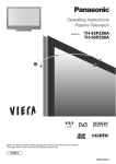
Operating Instructions
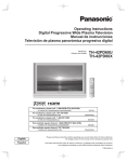
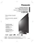
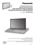
Video Monitor
Model No.
INPUT
SELECT
WV-LW1900
WV-LW2200
MENU
SELECT
AUDIO
ECO
Video Mon
itor WV-LW
2200
(This illustration represents WV-LW2200.)
Before attempting to connect or operate this product,
please read these instructions carefully and save this manual for future use.
No model number suffix is shown in this manual.
For U.S.A
This product has a fluorescent lamp that contains mercury.
Dispose may be regulated in your community due to environmental considerations. For disposal or recycling information,
please contact your local authorities, or the Electronic
Industries Alliance:
http://www.eiae.org
WARNING:
• This apparatus must be earthed.
• Apparatus shall be connected to a main socket outlet with a
protective earthing connection.
• The mains plug or an appliance coupler shall remain readily
operable.
• To prevent fire or electric shock hazard, do not expose this
apparatus to rain or moisture.
• The apparatus should not be exposed to dripping or splashing and that no objects filled with liquids, such as vases,
should be placed on the apparatus.
• All work related to the installation of this product should be
made by qualified service personnel or system installers.
• The connections should comply with local electrical code.
For Canada
CAUTION
This Class A digital apparatus complies with Canadian ICES003.
RISK OF ELECTRIC SHOCK
DO NOT OPEN
CAUTION: TO REDUCE THE RISK OF ELECTRIC SHOCK,
DO NOT REMOVE COVER (OR BACK).
NO USER-SERVICEABLE PARTS INSIDE.
REFER SERVICING TO QUALIFIED SERVICE PERSONNEL.
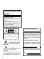
The lightning flash with arrowhead symbol,
within an equilateral triangle, is intended to
alert the user to the presence of uninsulated
"dangerous voltage" within the product's
enclosure that may be of sufficient magnitude to constitute a risk of electric shock to
persons.
The exclamation point within an equilateral
triangle is intended to alert the user to the
presence of important operating and maintenance (servicing) instructions in the literature
accompanying the appliance.
Power disconnection. Unit with or without ON-OFF switches
have power supplied to the unit whenever the power cord is
inserted into the power source; however, the unit is operational
only when the ON-OFF switch is in the ON position. Unplug the
power cord to disconnect the main power for all units.
2
For U.S.A
NOTE: This equipment has been tested and found to comply
with the limits for a Class A digital device, pursuant to Part 15
of the FCC Rules. These limits are designed to provide reasonable protection against harmful interference when the
equipment is operated in a commercial environment. This
equipment generates, uses, and can radiate radio frequency
energy and, if not installed and used in accordance with the
instruction manual, may cause harmful interference to radio
communications.
Operation of this equipment in a residential area is likely to
cause harmful interference in which case the user will be
required to correct the interference at his own expense.
FCC Caution: To assure continued compliance, (example use only shielded interface cables when connecting to computer or peripheral devices). Any changes or modifications
not expressly approved by the party responsible for compliance could void the user’s authority to operate this equipment.
For U.S.A
The serial number of this product may be found in the unit.
You should note the model number and serial number of this
unit in the space provided and retain this book as a permanent record of your purchase to aid identification in the event
of theft.
Model No.
Serial No.
Important Safety Instructions
1) Read these instructions.
2) Keep these instructions.
3) Heed all warnings.
4) Follow all instructions.
5) Do not use this apparatus near water.
6) Clean only with dry cloth.
7) Do not block any ventilation openings. Install in accordance with the manufacturer's instructions.
8) Do not install near any heat sources such as radiators, heat registers, stoves, or other apparatus (including amplifiers) that
produce heat.
9) Do not defeat the safety purpose of the polarized or grounding-type plug. A polarized plug has two blades with one wider
than the other. A grounding type plug has two blades and a third grounding prong. The wide blade or the third prong are
provided for your safety. If the provided plug does not fit into your outlet, consult an electrician for replacement of the obsolete outlet.
10) Protect the power cord from being walked on or pinched particularly at plugs, convenience receptacles, and the point
where they exit from the apparatus.
11) Only use attachments/accessories specified by the manufacturer.
12) Use only with the cart, stand, tripod, bracket, or table specified by the manufacturer, or sold with the apparatus. When a cart
is used, use caution when moving the cart/apparatus combination to avoid injury from tip-over.
S3125A
13) Unplug this apparatus during lightning storms or when unused for long periods of time.
14) Refer all servicing to qualified service personnel. Servicing is required when the apparatus has been damaged in any way,
such as power-supply cord or plug is damaged, liquid has been spilled or objects have fallen into the apparatus, the apparatus has been exposed to rain or moisture, does not operate normally, or has been dropped.
3
Limitation of liability
THIS PUBLICATION IS PROVIDED "AS IS" WITHOUT WARRANTY OF ANY KIND, EITHER EXPRESS OR IMPLIED, INCLUDING
BUT NOT LIMITED TO, THE IMPLIED WARRANTIES OF MERCHANTABILITY, FITNESS FOR ANY PARTICULAR PURPOSE, OR
NON-INFRINGEMENT OF THE THIRD PARTY'S RIGHT.
THIS PUBLICATION COULD INCLUDE TECHNICAL INACCURACIES OR TYPOGRAPHICAL ERRORS.
CHANGES ARE ADDED TO THE INFORMATION HEREIN, AT ANY TIME, FOR THE IMPROVEMENTS OF THIS PUBLICATION
AND/OR THE CORRESPONDING PRODUCT (S).
Disclaimer of warranty
IN NO EVENT SHALL Panasonic Corporation BE LIABLE TO ANY PARTY OR ANY PERSON, EXCEPT FOR REPLACEMENT OR
REASONABLE MAINTENANCE OF THE PRODUCT, FOR THE CASES, INCLUDING BUT NOT LIMITED TO BELOW:
(1) ANY DAMAGE AND LOSS, INCLUDING WITHOUT LIMITATION, DIRECT OR INDIRECT, SPECIAL, CONSEQUENTIAL OR
EXEMPLARY, ARISING OUT OF OR RELATING TO THE PRODUCT;
(2) PERSONAL INJURY OR ANY DAMAGE CAUSED BY INAPPROPRIATE USE OR NEGLIGENT OPERATION OF THE USER;
(3) UNAUTHORIZED DISASSEMBLE, REPAIR OR MODIFICATION OF THE PRODUCT BY THE USER.
4
CONTENTS
Important Safety Instructions .......................................................................................................... 3
Limitation of liability ......................................................................................................................... 4
Disclaimer of warranty ..................................................................................................................... 4
Preface ............................................................................................................................................ 6
Trademarks and registered trademarks .......................................................................................... 6
Precautions ..................................................................................................................................... 6
Precautions for installation .............................................................................................................. 8
Major operating controls and their functions ................................................................................... 9
■ Front View ................................................................................................................................. 9
■ Rear View .................................................................................................................................. 10
Turn on the power of the extension unit .......................................................................................... 12
Audio Volume Control ..................................................................................................................... 13
ECO Mode Activation/Deactivation ................................................................................................. 14
ECO mode activation .................................................................................................................... 14
ECO mode deactivation ................................................................................................................ 14
Video Adjustment and Setup ........................................................................................................... 15
Video adjustment .......................................................................................................................... 15
Screen setup ................................................................................................................................. 16
Language in the menus to be displayed ....................................................................................... 18
Operation time check .................................................................................................................... 19
Installation ....................................................................................................................................... 20
How to mount monitor stand ........................................................................................................ 20
How to remove monitor stand mounting bracket .......................................................................... 20
Screw holes for wall mounting bracket ......................................................................................... 20
Connections .................................................................................................................................. 21
Troubleshooting .............................................................................................................................. 23
Specifications .................................................................................................................................. 25
Standard Accessories ..................................................................................................................... 25
Appearance ..................................................................................................................................... 26
5
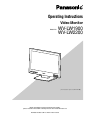
Preface
This is a video monitor provided with a 19"-type (WVLW1900) or a 22"-type (V) (WV-LW2200) LCD panel.
• Built-in full high-definition panel (for WV-LW2200)/highdefinition panel (for WV-LW1900) with high-speed
response
• Supporting HDMI, composite video signal and analog
RGB signal for personal computer (PC)
• HDMI, video (480p/720p/1080i/1080p) and audio
(1 ch) supported
• Composite video, automatically switchable between
NTSC and PAL system
• PC display capacity supporting resolutions from VGA
(640 x 480) to SXGA (1280 x 1024). Picture display position can be automatically adjusted.
• Audio input x1 and built-in speaker with max. output of
0.5 W
• On-screen setup menu
• Auto-volt power supply from 100 V AC to 240 V AC
* The supplied power cord shall be used exclusively for
this monitor. The cord supports 120 V AC only. To use
this product with different power source, replace the
power cord.
• The screw holes for wall mounting at the rear of this
monitor comply with the VESA (Video Electronics
Standards Association) standards (100 mm pitch).
* VESA: Video Electronics Standards Association
Trademarks and registered trademarks
HDMI, the HDMI logo and High-Definition Multimedia
Interface are trademarks or registered trademarks of HDMI
Licensing LLC.
Precautions
• Refer all work related to the installation of this product to qualified service personnel or system
installers.
• Do not block the ventilation opening or slots on the
cover.
• Do not drop metallic parts through slots.
This could permanently damage the apparatus. Turn the
power off immediately and contact qualified service personnel for service.
• Do not attempt to disassemble this product.
To prevent electric shock, do not remove screws or covers.
There are no user-serviceable parts inside. Contact
qualified service personnel for maintenance.
• Do not strike or give a strong shock to this product.
It may cause damage or allow water to enter this product.
6
• Do not expose this product to water or moisture.
Do not try to operate it in wet areas.
Take immediate action if this product gets wet. Turn the
power off and refer servicing to qualified service personnel. Moisture can damage this product and also
cause electric shocks.
• Cleaning
Turn the power off when cleaning the unit. Otherwise it
may cause injuries.
Do not use strong or abrasive detergents when cleaning
this product body.
Use a dry cloth to clean this product when it is dirty.
When the dirt is hard to remove, use a mild detergent
and wipe gently.
• Do not operate this product beyond its specified
temperature, humidity, or power source ratings.
Use this product under conditions where temperatures
are between 0 °C and + 40 °C {+32 °F to +104 °F}, and
humidity below 90 %.
The input power source for this product is 120 V AC, 60
Hz.
• Do not mount this product on places subject to constant vibrations. That may cause trouble or damage.
• Use only the supplied power cord.
• Be sure to remove this product if it is not in use.
• The surface of the LCD Panel is applied by special
coating.
Do not touch or wipe the surface with a hard or abrasive
object. Failure to observe this may cause damage to the
LCD panel.
• The LCD panel is made from a very precise technology.
Some bright and dark spots may exist on the monitor
screen.
It is operating normally if there are 99.99 % active pixels.
• Image persistence may appear on the LCD after a
static image with strong contrast is continuously
displayed.
Such a phenomenon is caused by an LCD characteristic. The persistent image will disappear after a period of
time.
cord:
• Via a power supply control unit
• Direct connection of the power supply plug to the
receptacle without fail
• Connection of the power supply cord to the breaker
with a contact gap of 3.0 mm or more. The breaker
should be designed to break all the lines between
the main power supply and this product except the
grounding connection.
• Installation place
• This product is designed to be used indoors. This
product is not operable outdoors.
• Keep approx. 5-centimeter space on the top, rear
and both lateral sides of this product.
• Install this product in a vibration-free place.
Installation in a vibrating place causes this product
to malfunction.
• Do not install this product in any place where it will
be subjected to direct sunlight for a long time or
close to heating or cooling equipment. Failure to
observe this may cause deformation, discoloration,
failure, or malfunction. Also keep this product away
from water droplets or water splashes.
• Screwing
• The screws must be tightened with an appropriate
tightening torque according to the material and
strength of the installation area.
• Do not use an impact driver. Use of an impact driver
may damage the screws.
• When a screw is tightened, make the screw at a
right angle to the surface. After tightening the
screws, perform visual check to ensure tightening is
enough and there is no backlash.
• Power switch
Even though the power switch is turned off, the power
supply will not be cut.
Unplug the power cord from the receptacle if this product is not used for a long time. When using the power
supply control unit, turn off the power of the power supply control unit.
• Notations
Refer to the label on the rear side of this product for the
ID, power supply and other notations of this product.
• Grounding
Ensure that the ground connection is properly and
securely made before use. If a grounding receptacle is
used, ensure that the ground resistance is 100 ohms or
less.
• Power supply
Be sure to make the ground connection before connecting the power plug of this product to the main power
supply. Also be sure to disconnect the ground after disconnecting the power plug of this product from the main
power supply if necessary. Any of the following circuit
breaking methods should be selected for the power
7
Precautions for installation
Installation work shall be performed in accordance with
the technology standard of the electric installation.
Grounding
A grounding connection must be made before connecting
the power plug of this product to the main power supply. If a
grounded outlet is used, check the ground resistance (100
Ω or less).
Power supply
Be sure to connect to ground prior to connection of the
power plug to the main power supply. For disconnection
from ground, be sure to disconnect the power plug from the
main power supply first. Be sure to connect the power cord
via any of the following breaking devices:
(1) Connect the power cord via a power supply control unit.
(2) Install this monitor near an electric outlet, and connect
the power cord via the power plug.
(3) Connect the power cord to the breaker with contact gap
of 3.0 mm or more of a distribution board. The breaker
should be designed to break the current flows to and
from all the electrodes connected to the main power
supply except the ground protective conductor.
Installation place
• This monitor is designed to be used indoors. This monitor is not operable outdoors.
• Keep the both side surfaces, top surface and rear surface of this monitor approximately 5 cm away from the
wall.
• Do not mount the monitor on places subject to constant
vibrations. That may cause trouble or damage.
• Do not install this system in any place where it will be
subjected to direct sunlight for a long time or close to
any air conditioning equipment. Failure to observe this
may cause deformation, discoloration, failure, or malfunction. Please keep this product away from water
droplets or water splashes.
• Avoid the following locations for installation.
• Locations where it may get wet from rain or water
splash
• Locations where a chemical agent is used such as a
swimming pool
• Locations subject to steam and greasy fumes such
as a kitchen and in the special environment of solvents and inflammable gas atmosphere
• Locations where radiation, x-ray, intense radio wave,
or strong magnetism is produced
• Locations on the sea or by the sea, and locations
where a corrosive gas is present
8
Screwing
• The screws must be tightened with an appropriate tightening torque according to the material and strength of
the installation area.
• Do not use an impact driver. Failure to observe this may
damage the screw.
• When a screw is tightened, make the screw at a right
angle to the surface. After tightening the screws, perform visual check to ensure tightening is enough and
there is no backlash.
If this system is not used any more, be sure to dismantle
this system.
Major operating controls and their functions
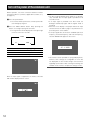
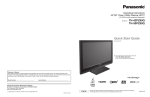
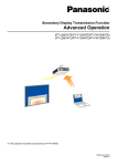
■ Front View
INPUT
SELECT
Video Monitor WV-LW2200
MENU
SELECT
AUDIO
ECO
w r
qe t yu
i
o
!0
(This illustration represents WV-LW2200.)
q Power button ( )
Powers on or off the monitor.
Note:
• Power is supplied via the power cord even while the
power button of the monitor set is off.
w Power indicator
This indicator lights green while power is supplied to this
monitor and lights orange in the ECO mode (☞ page
14). When this monitor power is turned off, it lights red.
e Input signal selection button (INPUT SELECT)
Every pressing this button can change input signals as
follows.
VIDEO
PC
t Selection buttons (SELECT: C, D), ECO button
These buttons move the cursor in setup menus.
C : Down
D : Up
The C button functions as the ECO button other than the
setup menus to activate the ECO mode (☞ page 14).
y Audio buttons (AUDIO: +, –)
These buttons adjust the audio volume level. These buttons increments or decrements the selected parameter
in setup menus.
u Reset switch
Restarts this monitor.
i Monitor stand
o LCD panel
Take care not to pinch your hands or fingers between
the LCD panel and the monitor stand.
HDMI
!0 Speaker
r Menu button (MENU)
Displays the main menu (☞ page 15). This button is also
used to determine the selected parameter in the setup
menus.
9
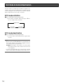
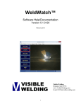
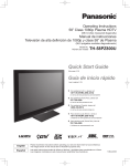
■ Rear View
@0
!1
!2
!3
!4 !5
!6 !7
!8 !9
(This illustration represents WV-LW2200.)
!1 Clamp
After connection of the power cord and HDMI cable,
remove the screw that secures the cord clamp and fasten the power cord and HDMI cable.
!2 Power input jack (AC IN)
Connect the power cord (accessory).
!7 Video output connector (VIDEO OUT)
Supplies a composite video signal accepted by the
VIDEO IN connector to another external device.
!3 Audio input connector (AUDIO IN)
With an audio cable connection, this connector accepts
an audio signal from an external device and supplies the
signal to the built-in speaker.
!8 Security slot
You can attach a lock that meets the industry standard
specification (3 to 3.26 mm x 7 to 7.26 mm x 3.5 to
4 mm).
Note:
• When HDMI is selected for input, audio output is provided not from this terminal but from the HDMI connector.
!4 HDMI input connector (HDMI)
Accepts an HDMI signal (video/audio) from an external
device.
For timing data this connector supports, refer to page 11
"Timing data chart for HDMI input".
!5 PC input connector (PC IN)
Accepts an analog RGB signal from a PC.
For timing data this connector supports, refer to page 11
"Timing data chart for PC input".
10
!6 VIDEO input connector (VIDEO IN)
Accepts a composite video signal from an external
device.
!9 Fall-prevention clamp
Use a strong cord or chain (locally procured) to secure
this monitor to a solid wall or column for fall prevention.
Remove the clamp when a mounting bracket for wall
installation is used.
@0 Screw holes for VESA mounting bracket (☞ page 20)
Timing data chart for PC input
This monitor supports the timing data listed as follows. The timing data are partly applicable to the items not listed in the table
below.
Resolution
Refresh
frequency (Hz)
Horizontal
frequency (kHz)
Dot clock
frequency (MHz)
Standards
60
31.5
25.175
Industry standard
72
37.9
31.500
VESA standard
75
37.5
31.500
VESA standard
56
35.1
36.000
VESA guideline
60
37.9
40.000
VESA guideline
72
48.1
50.000
VESA standard
75
46.9
49.500
VESA standard
60
48.4
65.000
VESA guideline
1024 x 768
70
56.5
75.000
VESA standard
75
60.0
78.750
VESA standard
1152 x 864
75
67.5
108.000
VESA standard
1280 x 960
60
60.0
108.000
VESA standard
60
64.0
108.000
VESA standard
75
80.0
135.000
VESA standard
1280 x 720
60
45.0
74.250
VESA standard
1360 x 768
60
47.7
85.500
VESA standard
640 x 480
800 x 600
1280 x 1024
* VESA: Video Electronics Standards Association
Timing data chart for HDMI input
This monitor supports the timing data listed as follows. The timing data are partly applicable to the items not listed in the table
below.
Resolution
Signal type
640 x 480
480p
59.940
31.469
25.175
CEA standard
480i
59.940
15.734
27.000
CEA standard
480p
59.940
31.469
27.000
CEA standard
576i
50.000
15.625
27.000
CEA standard
576p
50.000
31.250
27.000
CEA standard
720 x 480
720 x 576
1280 x 720
720p
1080i
1920 x 1080
1080p
Refresh
frequency (Hz)
Horizontal
frequency (kHz)
Dot clock
frequency (MHz)
Standards
60.000
45.000
74.250
CEA standard*
50.000
37.500
74.250
CEA standard
60.000
33.750
74.250
CEA standard*
50.000
28.125
74.250
CEA standard
60.000
67.500
148.500
CEA standard*
50.000
56.250
148.500
CEA standard
• CEA: Consumer Electronics Association
* CEA considers video timings with the refresh frequencies of 59.940 Hz and 60.000Hz as the equivalent video timing.
Exact video timings for 59.940 Hz can be calculated when adjusting numbers listed for 60.000 Hz by a factor of 1000/1001.
11
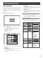
Turn on the power of the extension unit
Before operation, check the connections between monitors
and external devices (cameras, digital disk recorders, etc.).
(☞ page 21)
z Press the power button.
→ The monitor will be powered on, and the power indicator will light up in green.
x Press the INPUT SELECT button. Every pressing this
button can change input signals as follows:
→ The signal name will be displayed on the upper right
corner of screen for 3 seconds.
VIDEO
PC
On-screen indication
VIDEO
HDMI
PC
Note:
• The ECO mode (backlight off) (☞ page 14) is automatically activated after no input signal is provided for 10
seconds or more.
• If an input signal is provided in the ECO mode, the
backlight automatically lights and the regular mode is
activated.
• When the screen display is not proper with the PC input
selected, refer to the table in page 11 to perform the output setting of the connected PC.
• If an input signal does not meet the standards (dot clock
frequency, horizontal frequency, and vertical frequency),
"OUT OF RANGE" will appear on the screen.
HDMI
Input signal type
VIDEO input
HDMI input
PC input
• This monitor can be operated on a plug-and-play basis,
however, some settings are configurable on a PC but
not displayable on this monitor owing to the restrictions
regarding specifications. After ensuring that settings are
viewable on this monitor, complete the settings on a PC.
When no input signal is supplied to the monitor, "NO SIGNAL" will be displayed on the screen.
12
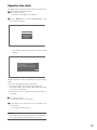
Audio Volume Control
z Pressing the audio buttons (AUDIO –/+) during image
display allows users to adjust the audio volume level.
When the button is pressed, the volume level appears
on the bottom of the screen.
– : Audio volume down
+ : Audio volume up
22
VOLUME
Item
Effect
Setting value
Volume
Down
Up
0
40
13
ECO Mode Activation/Deactivation
The ECO mode is a mode that can reduce the power consumption of this monitor by darkening or completely turning
off the backlight of the LCD panel. The power indicator
lights orange while the ECO mode is activated.
ECO mode activation
z Press the C button during image display.
→ ECO mode is activated. Every pressing the C button can change modes as follows:
Regular mode
ECO mode
(backlight off)
ECO mode
(reduced luminance)
ECO mode deactivation
z Press the D button during image display.
→ The ECO mode is deactivated and the regular mode
resumes.
Note:
• Buttons other than C and D buttons can deactivate the
ECO mode. However, the function assigned to the button to be pressed is also performed.
Example: Pressing the menu button in the ECO mode
deactivates the ECO mode, and then the main menu
screen appears.
• The ECO mode (backlight off) is automatically activated
after no input signal is provided for 10 seconds or more.
14
Video Adjustment and Setup
Video adjustment
Adjustment of this monitor will be performed in the VIDEO
ADJUST menu. The menu title display differs depending on
the selected input signal. Before adjustment, press the
INPUT SELECT button surely to select the input signal.
(☞ page 9)
z Press the menu button.
→ The top menu will be displayed.
• For HDMI input
The present signal is displayed in the style of "signal
type and refresh frequency" in accordance with the timing data table (☞ page 11).
• For PC input
The present signal is displayed in the style of "resolution
and refresh frequency" in accordance with the timing
data table (☞ page 11).
Note:
• The respective setting items are allowed to set up different values in regard to each input signal.
• "TINT" can be adjusted only if the input signal is of the
NTSC system or HDMI.
VIDEO ADJUST
SCREEN SETUP
MAINTENANCE
LANGUAGE
EXIT
c Use the C/D buttons to select the item to be adjusted,
and press the -/+ buttons to adjust the screen.
Item
BRIGHTNESS
x Use the C/D buttons to select "VIDEO ADJUST", and
press the menu button.
→ The VIDEO ADJUST menu will be displayed.
Present input signals are displayed in the menu title.
VIDEO input:
VIDEO
For HDMI input: HDMI
For PC input:
PC
Menu title
Effect
Darker Brighter
-20
+20
Lower Higher
-20
+20
Softer Sharper
-7
+7
COLOR
(except PC)
Lower Higher
-20
+20
TINT (Only for
NTSC and HDMI)
Redder Greener
-20
6500K:
Red is intensified.
(standard)
9300K:
Blue is intensified.
User:
Depending on the
settings of "USER
COLOR R", "USER
COLOR G" and
"USER COLOR B".
+20
Low High
-20
+20
Low High
-20
+20
Low High
-20
2.2:
Standard
1.8:
Dark portions on
images become
brighter.
+20
CONTRAST
SHARPNESS
(except PC)
COLOR
TEMPERATURE
Input signal type
VIDEO
BRIGHTNESS
CONTRAST
SHARPNESS
COLOR
TINT
COLOR TEMP
6500K
USER COLOR-R
USER COLOR-G
USER COLOR-B
GAMMA
2.2
NORMAL SETTINGS
EXIT
NTSC
00
00
00
00
00
00
00
00
An input signal type appears at the right of the menu title
as follows:
• For VIDEO input
NTSC : When a video signal input of the NTSC system is
entered or if there is no signal
PAL : When a video signal input of the PAL system is
entered
Setting value
USER COLOR R
USER COLOR G
USER COLOR B
GAMMA
15
Note:
• [USER COLOR R], [USER COLOR G], and [USER
COLOR B] can be adjusted only if [User] has been chosen for [COLOR TEMPERATURE].
v To reset the video adjustment to the default, use the
C/D buttons to select "NORMAL SETTINGS" and press
the menu button.
→ The settings of only input signals (VIDEO, HDMI, and
PC) currently displayed are reset to the factory
default.
Screen setup
The image position and size in contradistinction to the LCD
panel are adjusted.
z Press the menu button. The main menu screen appears.
(☞ page 15)
x Use the C/D buttons to select "SCREEN SETUP", and
press the menu button.
→ The screen setup menu appears.
VIDEO ADJUST
SCREEN SETUP
MAINTENANCE
LANGUAGE
EXIT
b Select "EXIT", and press the menu button.
→ The main menu screen resumes.
n Select "EXIT" on the main menu screen, and press the
menu button.
→ The regular screen resumes.
Note:
• The regular screen automatically resumes after no operation is performed for approximately 10 seconds.
An input signal type appears at the right of the menu title as
follows:
• For VIDEO input
NTSC:When a video signal input of the NTSC system or
no signal is provided
PAL : When a video signal input of the PAL system is
provided
• For HDMI input
The present signal is displayed in the style of "scanning
system and refresh frequency" in accordance with the
timing data table (☞ page 11).
• For PC input
The present signal is displayed in the style of "resolution
and refresh frequency" in accordance with the timing
data table (☞ page 11).
c Use the C/D buttons to select "AUTO", and press the
menu button.
→ The automatic adjustment starts.
Note:
Present input signals are displayed in the menu title.
For VIDEO input: VIDEO
For HDMI input: HDMI
For PC input: PC
Menu title
PC
H-POSITION
V-POSITION
SCAN
CLOCK
PHASE
AUTO
EXIT
16
• The screen flickers during automatic adjustments, but
this phenomenon is not a malfunction.
• Automatic adjustment for VIDEO input makes the scanning ratio 4:3 full.
• Automatic adjustment takes several seconds to over 10
seconds depending on the conditions of the video signal.
If an optimal screen cannot be obtained after automatic
adjustment, the following operations may help:
Input signal type
1280 x 1024 @60 Hz
00
00
16 : 9
00
00
v Use the C/D buttons to select the item to be adjusted,
and press the -/+ buttons to adjust the screen.
Item
H-POSITION
Effect
n Select EXIT on the main menu screen, and press the
menu button.
→ The regular screen resumes.
Setting range
Leftward Leftward
-40
+40
V-POSITION
(except video)
Lower Upper
-20
+20
CLOCK
(only for PC)
Smaller Larger
-20
+20
PHASE
(only for PC)
Minimum Maximum
0
+63
b Select EXIT, and press the menu button.
→ The main menu screen resumes.
Note:
• The regular screen automatically resumes after no operation is performed for approximately 10 seconds.
• When signals are received from a PC, toggling the
power on and off activates automatic adjustment.
Note:
• "Clock" and "Phase" are displayed only when PC input is
provided.
• "Vertical position" is not displayed when VIDEO input is
provided.
• The settings of "Horizontal position" and "Vertical position" for HDMI input range from –10 to +10.
• The setting of "Horizontal position" for VIDEO input range
from –10 to +10.
Table of scan settings
Selectable scanning ratio
4:3 video signal 16:9 video signal
Description
VIDEO input
HDMI input
PC input
4:3 full
4:3 full
4:3
The whole image is displayed
with the aspect ratio of 4:3. The
far-right and far-left portions of
the screen are not used.
–
The image without surrounding
areas is displayed with the aspect
ratio of 4:3. The far-right and farleft portions of the screen are not
used.
4:3 zoom
16:9 full
16:9 zoom
ー
4:3 zoom
16:9 full
16:9 zoom
Dot by dot
16:9
–
Dot by dot
The whole image is displayed on
the whole screen.
The image without surrounding
areas is displayed on the whole
screen.
The whole image is displayed
with one-to-one relation between
image pixel count and screen
pixel count. The display size
depends on the image pixel
count. If the image pixel count is
smaller than the screen pixel
count, the surrounding areas of
the screen are not used.
17
Language in the menus to be displayed
A language in the screen is selectable.
z Press the menu button.
→ The main menu appears. (☞ page 15)
x Use the C/D buttons to select "LANGUAGE", and press
the menu button.
VIDEO ADJUST
SCREEN SETUP
MAINTENANCE
LANGUAGE
EXIT
→ The language menu appears.
LANGUAGE
ENGLISH
FRANÇAIS
DEUTSCH
ESPAÑOL
ITALIANO
EXIT
cUse the C/D buttons to select a language to be used,
and press the menu button.
→ The language is selected.
v Select EXIT, and press the menu button.
→ The main menu screen resumes.
Note:
• When any language other than English is selected, the
menu title and "EXIT" are described in the selected language.
b Select "EXIT" on the main menu screen, and press the
menu button.
→ The regular screen resumes.
Note:
• The regular screen automatically resumes after no operation is performed for approximately 10 seconds.
18
Operation time check
The approximate time period of the monitor operation from
startup to the present can be viewed.
z Press the menu button.
→ The main menu appears. (☞ page 15)
x Use the C/D buttons to select "MAINTENANCE", and
press the menu button.
VIDEO ADJUST
SCREEN SETUP
MAINTENANCE
LANGUAGE
EXIT
→ The number of elapsed years since monitor startup
appears.
Since the first operation of the monitor about
01 years have passed.
In order to maintain the safety and function of the
monitor, we recommend to perform a product check.
EXIT
Periodic inspections shall be conducted to use the monitor
safely.
Is any of the following phenomena observed?
• Smoke, burnt odor, or unusual sound is detected.
• The power cord or power plug is abnormally hot. A flaw
or a scratch is observed.
• An abnormal event or trouble other than the above is
observed.
cPress the menu button.
→ The main menu screen resumes.
v Select "EXIT" on the main menu screen, and press the
menu button.
→ The regular screen resumes.
Note:
• The regular screen automatically resumes after no operation is performed for approximately 10 seconds.
19
Installation
Important:
• Before installation work, remove all the connected cables and turn off the power of this monitor.
• Do not block the ventilation opening.
• Install this monitor at a vibrationless place. Installation of this monitor at a constantly vibrating place may cause trouble.
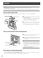
How to mount monitor stand
The monitor stand (accessory) is mounted. Use of supplied cushioning protects this monitor from being damaged.
Monitor stand mounting
screw (M4) (accessory)
Monitor stand (accessory)
Rectangular holes
Protrusions
Monitor stand
mounting bracket
z Mount the monitor stand (accessory) onto the monitor
stand mounting bracket.
Ensure that the protrusions of the monitor stand mounting bracket pass through the rectangular holes on the
bottom face of the monitor stand respectively.
x Use 4 pieces of the monitor stand mounting screws
(M4 x 10) (accessories) to secure the monitor stand firmly.
Recommended tightening torque: 0.98 N·m {10 kgf·cm}
Cushioning
How to remove monitor stand mounting bracket
z Remove 1 piece of the stand cover mounting screw
(M4 x 15), and then remove the stand cover.
x Remove 4 pieces of the screws (M4 x 15) securing the
monitor stand mounting bracket, and then remove the
mounting bracket.
Note:
Mounting screw (M4)
Stand cover
Mounting screw (M4)
Monitor stand
mounting bracket
• The removed stand cover, monitor stand mounting
bracket and screws should be retained for future use.
• To mount the monitor stand mounting bracket and stand
cover again, observe the following recommended tightening torques:
Monitor stand mounting bracket: 0.98 N·m {10 kgf·cm}
Stand cover: 0.784 N·m {8 kgf·cm}
Screw holes for wall mounting bracket
• Check the weights of the wall mounting bracket and this monitor.
• First, check the wall strength of the mounting position because the pull-out strength of the mounting position should be at
least 5 times more than the total weight of the wall mounting bracket and this monitor.
20
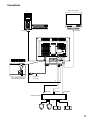
Connections
Another video monitor
PC
PC output
* Use a cord clamp to fasten the
HDMI cable and power cord.
Video input
Power cord
(accessory)
Audio output
HDMI output
Video output
Digital disk recorder
21
■ Cable connection
To provide VIDEO input, connect the video output to the VIDEO input connector on the rear face of this monitor with a coaxial
cable or to the HDMI input connector on the rear face of this monitor with an HDMI cable.
The maximum length of the coaxial cable shall be observed as follows:
Cable type
3C-2V
5C-2V
7C-2V
10C-2V
Length
250 m
500 m
600 m
800 m
The HDMI cable shall be 10 m or less, and an extension cable and a repeater should not be used.
Use of Panasonic HDMI cables is recommended.
Cable type
RP-CDHG05
RP-CDHG10
RP-CDHG15
RP-CDHG20
RP-CDHG30
RP-CDHG50
RP-CDHG80
RP-CDHG100
Length
0.5 m
1m
1.5 m
2m
3m
5m
8m
10 m
■ Connection with two or more video monitors
When plural video monitors are connected, connect the VIDEO input connector of another video monitor to the video output
connector of this monitor. Use a coaxial cable for connection.
Up to 10 video monitors can be connected. If 11 or more video monitors are connected, image quality may be degraded. The
total length of each cable should not exceed 150 m.
■ Digital disk recorder connection
• To play video:
Connect the video output connector of the digital disk recorder to the VIDEO input connector or HDMI input connector of
this monitor with a coaxial cable or an HDMI cable.
• To provide audio input:
Connect the audio output connector of the digital disk recorder to the audio input connector of this monitor with an audio
cable.
■ PC connection
Connect the video output (analog RGB) of a PC to the PC input connector of this monitor. The length of a PC cable shall be 3 m
or less.
22
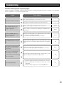
Troubleshooting
Check the following before requesting repair.
Contact your dealer if a problem cannot be solved even after checking and trying the solution, a problem is not described
below, or a problem is concerned with installation work.
Problem
Cause · Remedy
Reference page
Is the power plug properly connected to the outlet?
–
Is the power cord fully inserted into the power input jack?
–
The power cannot be turned on.
Are the cables properly inserted into the connectors?
10, 21
Are the cables connected to the signal-type-compatible input
connectors?
10, 21
"OUT OF RANGE" appears in
the center of the screen, and no
image is displayed.
When the PC input signal is not compliant with the specifications
of this monitor, no image is displayed.
→ Check the specifications of the connected PC.
11, 16
The display position is not proper.
Perform automatic adjustment in the screen setup menu. If the
display position is not properly adjusted, perform manual adjustment.
15
No response is observed when
the buttons on the front panel
are pressed.
• Press the reset switch to restart this monitor.
• Check the cables are properly inserted into the connectors.
"NO SIGNAL" appears in the
center of the screen, and no
image is displayed.
The screen is completely dark,
and nothing can be viewed.
When the power indicator lights orange, the ECO mode is active.
Press the D button to deactivate the ECO mode.
9, 10
14
The screen is dim.
No sound is generated.
• Check the cables are properly inserted into the connectors.
• When an HDMI input is provided, the audio input connector
is disabled.
Check the audio setting of the connected HDMI device.
9
23
Problem
Cause · Remedy
Inspect the power cord and
power plug occasionally.
The power cord, connectors, or
power plug is partly hot during
use.
The power cord gets hot when
bent or stretched.
24
• The power cord, connectors, or power plug is damaged.
Continued use of the damaged power cord, connectors, or
power plug may cause electric shock or fire.
Remove the power plug from the outlet immediately, and
contact the dealer for repair.
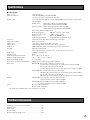
Specifications
■ Video monitor
Power source
Power consumption
120 V AC, 60 Hz
44 W (WV-LW1900), 51 W (WV-LW2200)
1 W or less at power off (power indicator red)
Display panel
18.5 V type (WV-LW1900)/21.6 V type (WV-LW2200) TFT LCD, built-in cold-cathode
tube backlight
Display area:
410mm (W) x 230 mm (H) (WV-LW1900)
478 mm (W) x 269 mm (H) (WV-LW2200)
Number of pixels: 1 366 x 768, High- definition (WV-LW1900)
1 920 x1 080, Full high-definition (WV-LW2200)
Aspect ratio (width-to-length): 16:9
Maximum brightness
300 cd/m2 (screen center, white)*
Maximum contrast ratio
1,000:1 (screen center)*
Display colors
Approx. 16 700 000 colors
Viewing angle (L/R/U/D)
85°/85°/80°/80° (contrast ratio 10:1)*
Television
Composite input: NTSC/PAL (automatically switchable)
Horizontal resolution
500 or more TV lines
VIDEO input
1.0 V [P-P] composite/75 Ω, BNC connector
Video output
Loop-through output, auto-termination, BNC connector
HDMI input
HDMI standards, digital video/audio signals, type A connector
PC input
R/G/B: 0.7 V [P-P] 75 Ω
Horizontal/vertical synchronization: TTL, mini D-sub 15-pin connector
Audio input
–8 dB/Hi-Z, RCA pin jack
Speaker output
0.5 W
Ambient operating temperature
0 °C - +40 °C {32 °F - 104 °F}
Ambient storage temperature
–20 °C - +60 °C {–4 °F - +140 °F}
Ambient operating humidity
Less than 90 %
Screw holes for wall mounting bracket
100 mm pitch (compliant with VESA standards)
Dimensions
WV-LW1900: 463 mm (W) x 374 mm (H) x 235 mm (D)
{18-7/32" (W) x 14-23/32" (H) x 9-1/4" (D)} (monitor stand included)
463 mm (W) x 321 mm (H) x 78 mm (D)
{18-7/32" (W) x 12-5/8" mm (H) x 3-1/16" (D)} (monitor stand excluded)
WV-LW2200: 531 mm (W) x 414 mm (H) x 235 mm (D)
{20-29/32" (W) x 16-5/16" (H) x 9-1/4" mm (D)} (monitor stand included)
531 mm (W) x 361 mm (H) x 78 mm (D)
{20-29/32" (W) x 14-7/32" (H) x 3-1/16" mm (D)}(monitor stand excluded)
Weight
WV-LW1900: 7 kg {15.45 lbs} {(monitor stand included)/
5.6 kg {12.36 lbs} (monitor stand excluded)
WV-LW2200: 8 kg {17.66 lbs} (monitor stand included)/
6.6 kg {14.57 lbs} (monitor stand excluded)
Finish
Monitor: Solid black metallic
Monitor stand: Solid black
* The values are standard values of the LCD panel to be used.
Standard Accessories
Operating instructions (This Document) .......................... 1 pc.
Warranty card ................................................................... 1 pc.
Power cord ....................................................................... 1 pc.
Monitor stand ................................................................... 1 pc.
Monitor stand mounting screw.......................................... 4 pcs.
25
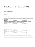
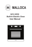
Appearance
WV-LW1900
INPUT
SELECT
5°
15°
181.5
{7-5/32"}
100
{3-15/16"}
181.5
{7-5/32"}
233 {9-3/16"}
374 {14-23/32"}
321 {12-5/8"}
463 {18-7/32"}
100 {3-15/16"}
78 {3-1/16"}
48 {1-27/32"}
30 {1-3/16"}
Video Monitor WV-LW1900
MENU
SELECT
AUDIO
265 {10-7/16"}
53
{2-3/32"}
ECO
235 {9-1/4"}
WV-LW2200
78 {3-1/16"}
INPUT
SELECT
Video Monitor WV-LW2200
MENU
SELECT
15°
215.5
{8-15/32"}
100
{3-15/16"}
215.5
{8-15/32"}
100 {3-15/16"}
5°
233 {9-3/16"}
361 {14-7/32"}
531 {20-7/8"}
414 {16-5/16"}
48 {1-27/32"}
30 {1-3/16"}
AUDIO
265 {10-7/16"}
53
{2-3/32"}
ECO
235 {9-1/4"}
(Unit: mm/inch)
26
27
Panasonic System Solutions Company,
Unit Company of Panasonic Corporation of North America
www.panasonic.com/business/
For customer support, call 1.800.528.6747
Three Panasonic Way 2H-2, Secaucus, New Jersey 07094
Panasonic Sales Company
Panasonic Puerto Rico, Inc.
AVE 65de Inf, Km 9.5 Carolina, PR 00985
(787)750-4300
Panasonic Canada Inc.
5770 Ambler Drive, Mississauga, Ontario, L4W 2T3 Canada
(905)624-5010
http://www.panasonic.ca
© Panasonic Corporation 2009
Nt0609-0
3TR006217ABA
Printed in Taiwan