1
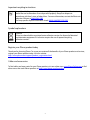
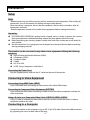
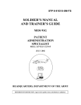
PD370/PD420/PD470/PD520 Special Home Theater Display User’s Manual www.PlanarHomeTheater.com Planar Systems, Inc. Corporate Headquarters 1195 NW Compton Drive Beaverton, OR 97006-1992 Planar Customer Support Telephone: US: 1-866-PLANAR1 (866) 752-6271 Outside US: (503) 748-5799 E-mail: [email protected] Online Technical Library: http://www.planar.com/support Hours: M-F, 3am-7pm ET, 11am-3am GMT 1 Preface About this manual This manual is designed for use with the PD370/PD420/PD470/PD520 Home Theater. Information in this document has been carefully checked for accuracy; however, no guarantee is given to the correctness of the contents. The information in this document is subject to change without notice. Copyright Copyright 2007 This document contains proprietary information protected by copyright. All rights are reserved. No part of this manual may be reproduced by any mechanical, electronic or other means, in any form, without prior written permission of the manufacturer. Trademarks All trademarks and registered trademarks are the property of their respective owners. FCC compliance This device complies with Part 15 of the FCC Rules. Operation is subject to the following two conditions. (1) This device may not cause harmful interference, and (2) This device must accept any interference received, including interference that may cause undesired operation. Federal communications commission (FCC) statement This equipment has been tested and found to comply with the limits for a Class B digital device, pursuant to part 15 of the FCC Rules. These limits are designed to provide reasonable protection against harmful interference in a residential installation. This equipment generates, uses and can radiate radio frequency energy and, if not installed and used in accordance with the instructions, may cause harmful interference to radio communications. However, there is no guarantee that interference will not occur in a particular installation. If this equipment does cause harmful interference to radio or television reception, which can be determined by turning the equipment off and on, the user is encouraged to try to correct the interference by one or more of the following measures: Reorient or relocate the receiving antenna. Increase the separation between the equipment and the receiver. Connect the equipment to an outlet on a circuit different from that to which the receiver is connected. Consult the dealer or an experienced radio/TV technician for help. 2 Important recycling instructions Lamp(s) inside this product contains mercury. This product may contain other electronic waste that can be hazardous if not disposed of properly. Recycle or dispose in accordance with local, state, or federal laws. For more information, contact the Electronic industries Alliance at WWW.EIAE.ORG For lamp specific disposal information check WWW.LAMPRECYCLE.ORG Symbol explanations Disposal: Do not use household or municipal waste collection services for disposal of electrical and electronic equipment. EU countries require the use of separate recycling collection services. Register your Planar product today Thank you for choosing Planar. To assure you receive all the benefits of your Planar product and services, register your Planar product today. Visit our website: http://www.planar.com/support/product_registration.html Cables and accessories To find cables and accessories for your Planar product, visit our online store: www.PlanarOnline.com or find other stores that stock Planar products at http://www.planar.com/howtobuy. 3 Table of Contents Important Safety Instructions..................................................................................................................... 5 Overview.................................................................................................................................................... 7 Features .............................................................................................................................................. 7 Package Contents ............................................................................................................................... 7 Identifying Controls and Connections ............................................................................................... 8 Front Panel ................................................................................................................................. 8 Control Panel.............................................................................................................................. 8 Connection Panel ....................................................................................................................... 8 Connection Panel continued....................................................................................................... 9 Rear panel .................................................................................................................................. 9 Installation................................................................................................................................................ 10 Setup ................................................................................................................................................ 10 Notes ........................................................................................................................................ 10 Unpacking ................................................................................................................................ 10 This monitor can be connected to any video source equipment utilizing the following interfaces: ................................................................................................................................. 10 Connecting the Power Cord ..................................................................................................... 10 Connecting to Video Equipment ...................................................................................................... 10 Connecting Using HDMI Cable (BEST) ................................................................................. 10 Connecting to Component Video Equipment (BETTER)........................................................ 10 Using a S-video or a Composite Video Cable (VIDEO/S-VIDEO) (GOOD) ......................... 10 Connecting to a Computer ............................................................................................................... 10 Basic operation......................................................................................................................................... 11 Info ................................................................................................................................................... 11 A. Connecting the Power Cable............................................................................................... 11 B. Turning Power On ............................................................................................................... 11 C. Selecting Input Source ........................................................................................................ 11 D. Turning Power Off .............................................................................................................. 11 Using the Menu Screen .................................................................................................................... 11 Remote control......................................................................................................................... 12 OSD (On Screen Display) Menu Function .............................................................................. 13 OSD Operation......................................................................................................................................... 16 Structure of OSD Menus (PC Mode) ............................................................................................... 16 A. Image Setting ...................................................................................................................... 16 B. Display Setting .................................................................................................................... 16 C. Audio Setting....................................................................................................................... 17 D. Setup.................................................................................................................................... 17 E. Menu Setting........................................................................................................................ 17 F. Clock/Timer Setting ............................................................................................................. 18 Structure of OSD Menus (Video Mode) .......................................................................................... 18 A. Image Setting ...................................................................................................................... 18 B. Display Setting .................................................................................................................... 19 C. Audio Setting....................................................................................................................... 19 D. Setup.................................................................................................................................... 19 E. Menu Setting........................................................................................................................ 20 F. Clock/Timer Setting ............................................................................................................. 20 Troubleshooting ....................................................................................................................................... 21 Product specifications .............................................................................................................................. 22 Declaration of Conformity ....................................................................................................................... 24 4 Important Safety Instructions This product is designed and manufactured to operate within defined design limits, and misuse may result in electric shock or fire. To prevent the product from being damaged, the following rules should be observed for the installation, use and maintenance of the product. Read the following safety instructions before operating the display. Keep these instructions in a safe place for future reference. To avoid the risk of electric shock or component damage, switch off the power before connecting other components to the monitor. Unplug the power cord before cleaning the monitor. A damp cloth is sufficient for cleaning the monitor. Do not use a liquid or a spray cleaner for cleaning the product. Do not use abrasive cleaners. Always use the accessories recommended by the manufacturer to insure compatibility. When moving the monitor from an area of low temperature to an area of high temperature, condensation may form on the housing. Do not turn on the monitor immediately after this to avoid causing fire, electric shock or component damage. Do not place the monitor on an unstable cart, stand, or table. If the monitor falls, it can injure a person and cause serious damage to the appliance. Use only a cart or stand recommended by the manufacturer or sold with the monitor. A distance of at least 3 feet should be maintained between the monitor and any heat source, i.e. radiator, heater, oven, amplifier etc. Do not install the product close to smoke. Operating the product close to smoke or moisture may cause fire or electric shock. Slots and openings in the back and bottom of the cabinet are provided for ventilation. To ensure reliable operation of the monitor and to protect it from overheating, be sure these openings are not blocked or covered. Do not place the monitor in a bookcase or cabinet unless proper ventilation is provided. Never push any object into the slot on the monitor cabinet. Do not place any objects on the top of the product. It could short circuit parts causing a fire or electric shock. Never spill liquids on the monitor. The monitor should be operated only from the type of power source indicated on the label. If you are not sure of the type of power supplied to your home, consult your dealer or local power company. The power cable must be replaced when using different voltage from that specified in the User Manual. For more information, contact your dealer. Do not overload power strips and extension cords. Overloading can result in fire or electric shock. The wall socket shall be installed near the equipment and shall be easily accessible. Only the marked power source can be used for the product. Any power source other than the specified one may cause fire or electric shock. Do not touch the power cord during lightning. To avoid electric shock, avoid handling the power cord during electrical storms. Unplug the unit during a lightening storm or when it will not be used for long period of time. This will protect the monitor from damage due to power surges. Do not attempt to repair or service the product yourself. Opening or removing the back cover may expose you to high voltages, the risk of electric shock, and other hazards. If repair is required, please contact your dealer and refer all servicing to qualified service personnel. Keep the product away from moisture. Do not expose this appliance to rain or moisture. If water penetrates into the product, unplug the power cord and contact your dealer. Continuous use in 5 this case may result in fire or electric shock. Do not use the product if any abnormality occurs. If any smoke or odor becomes apparent, unplug the power cord and contact your dealer immediately. Do not try to repair the product yourself. Avoid using dropped or damaged appliances. If the product is dropped and the housing is damaged, the internal components may function abnormally. Unplug the power cord immediately and contact your dealer for repair. Continued use of the product may cause fire or electric shock. Do not install the product in an area with heavy dust or high humidity. Operating the product in environments with heavy dust or high humidity may cause fire or electric shock. Follow instructions for moving the product. Ensure that the power connector and any other cables are unplugged before moving the product. Hold the power connector when removing the power cable. Pulling the power cable itself may damage the wires inside the cable and cause fire or electric shock. When the product will not be used for an extended period of time, unplug the power connector. To avoid risk of electric shock, do not touch the connector with wet hands. Insert batteries in accordance with instructions. Incorrect polarities may cause damage and leakage of the batteries, operator injury and contamination the remote controller. If any of the following occurs please contact the dealer. 6 Overview PD370/PD420/PD470/PD520 are native 1920 x 1080 HDTV monitors and can display true 16.7M colors (8-bit/color). . Features - High brightness - Dynamic contrast ratio (except PD370) - Fast response time - High color saturation - Max resolution 1920 x 1080(Full HD format) - Ultra wide viewing angle :176(H)/ 176(V) - Support PIP/PAP function - OSD in 12 languages - 2 HDMI inputs with HDCP key protection - Rear IR sensor - Tablestand included Package Contents Open the package and ensure that you have the following items: Item 1 Power cord US type. 2 Power cord UK type. 3 Power cord EU type. 4 Component Cable 5 Remote Control with AAA batteries 6 CD (User’s manual) 7 User’s Guide 8 Finishing Cloth 7 Identifying Controls and Connections Front Panel LED Light and Front IR Sensor Control Panel Connection Panel 90 degree rotation 8 Connection Panel continued 90 degree rotation │ is power on ○ is power off Main power –Switch & AC socket Power Cord AC Power cord The power cord is used to power the LCD monitor from a standard wall outlet. Connect the power cord into main power of the monitor where off. Input: 100-240V~ 3A 50/60Hz “│” is power on, “○” is power Note: PD520 signal connections are on the left side only when viewing the monitor from the rear as shown in the next figure. The PD520 power connection is on the right side from the same perspective. Rear panel Rear IR Sensor 9 Installation Setup Notes • Before connecting, turn off the monitor and any connected source equipment. After making all connections, turn on the monitor first before turning on other devices. When connecting a computer, be sure that the computer is the last device turned on, after all connections are made. • Read the operation manuals of the video source equipment before making connections. Unpacking PD370/PD420/PD470/PD520 is packed inside a boxed carton. In order to protect the monitor during transportation, additional packing material has been placed within the carton. Before unpacking your monitor, prepare a stable, level, and clean surface near a wall outlet for your monitor. Set the monitor box in an upright position and open from the top of the box before removing the top packaging material. This monitor can be connected to any video source equipment utilizing the following interfaces: High Definition Multimedia Interface (HDMI) Component (YPbPr) Composite Video S-Video HD-15 for VGA SCART (using Component 1 and Video 1) Connecting the Power Cord Plug the supplied power cord into the AC socket on the rear of the monitor. Connecting to Video Equipment Connecting Using HDMI Cable (BEST) Use a HDMI cable when connecting to video sources that utilize HDMI output. Connecting to Component Video Equipment (BETTER) Use a component cable when connecting to video sources that utilize component interfaces for video connection. Using a S-video or a Composite Video Cable (VIDEO/S-VIDEO) (GOOD) Using a S-video or a composite video cable to connect to video sources that utilize s-video or composite interfaces for video Connecting to a Computer Connect the monitor to the computer using an HD 15-pin VGA cable. Secure the cable connectors by tightening the screws on both sides of the plug. 10 Basic operation Connect the required external source equipment to the monitor before following these procedures. Info The OSD is automatically preset to English. To change the on-screen display language, refer to section E of the OSD Menu Function on page 19. A. Connecting the Power Cable Connect the power cord to the power cord connector on the back of the monitor. Plug the power cord into an AC wall socket and press power switch to “│” to power on, or “○” to power off the monitor. B. Turning Power On Once power switch is “on” (see above), press the Power ON button on the side of the monitor or remote control. C. Selecting Input Source To select the Input Source for the monitor, press the SOURCE button on the side of the monitor or press the desired source key on the remote control. Also, pressing the AUTO key on the remote control will cycle to the next active source input. D. Turning Power Off To turn off the monitor, press the Power OFF button on the side of the monitor or remote control. Using the Menu Screen The image and monitor settings can be adjusted through the MENU as listed on the monitor button panel or remote control using the following procedures: 11 Remote control ITEM On OFF ENTER MENU MUTE Volume + Volume – EXIT MODE AUTO INFO PIP SWAP 16:9 4:3 Letterbox S-Video AV1 AV2 Video 1 Video 2 HDMI 1 HDMI 2 PC Freeze FUNCTION Monitor on Monitor off Up Left Right Down Enter To enter OSD menu Audio mute Volume increase Volume decrease Exit To choose display mode (Sport, Theater, Game, Vivid, User defined) Search next active port To indicate the status To choose PIP/PBP function To exchange PIP/PBP function Aspect ratio 16:9 Aspect ratio 4:3 To choose letterbox aspect ratio To choose S-Video source To choose Composite source 1 To choose Composite source 2 To choose Component source 1 To choose Component source 2 To choose HDMI source 1 To choose HDMI source 2 For VGA choice To freeze the display motion Note 1: Inserting the batteries Insert two AAA batteries into the remote control. Make sure the (+) and (-) symbols on the batteries are matched with the (+) and (-) symbols inside the battery compartment. Re-attach the battery cover. Note 2: Precautionary Tips for Inserting the Batteries: Only use the specified AAA batteries. Do not mix new and old batteries. This may result in cracking or leakage that may pose a fire risk or lead to personal injury. Inserting the batteries incorrectly may also result in cracking or leakage that may pose a fire risk or lead to personal injury. Dispose of the batteries in accordance with local laws and regulations. Keep the batteries away from children and pets. 12 OSD (On Screen Display) Menu Function Video Mode Main Menu Image Settings Sub-Menu Audio Settings Setup Description Setting Scheme Choose display mode User, Sport, Game, Theater, Vivid Brightness Adjust the brightness of the screen 0~100 Contrast Adjust the contrast of the screen 0~100 Saturation Adjust the picture saturation of the screen 0~100 Hue Adjust the picture hue of the screen 0~100 Sharpness Adjust the sharpness of the screen 0~24 Reset Reset to the default value Yes, No Gamma Adjust the Gamma level of the screen , 1.8, 2.2, 2.5 Color Temps Adjust the color temperature of the screen , User,5000K, 6500K, 7500K,9300K Dynamic contrast Enable dynamic contrast ratio On, Off Advanced Display Settings Sub-Submenu Temporal NR Adjust the noise deduction Low, Adaptive, Off, High, Medium, MPEG NR Adjust MPEG NR 0~63 Aspect Ratio Adjust the aspect ratio of the screen 16:9, 4:3, Letter Box, Native Overscan Adjust overscan 0~10 Top Mask Choose top mask 0~100 Bottom Mask Choose bottom mask 0~100 Reset Reset to the default value Yes, No Stereo/SAP Choose the audio mode Stereo, Mono, SAP Bass Adjust Bass volume -10~10 Treble Adjust Treble volume -10~10 Balance Adjust the balance of the screen -10~10 Reset Reset to the default value Yes, No Main Auto Scan Auto Scan On, Off Main Source Select Select Main Source Searching, PC, HDMI 1, HDMI 2, Video 1, Video 2, AV1, AV2, S-Video, SCART Main Source Activate Activate the main source (Enable or Disable) PC, HDMI 1, HDMI 2, Video 1, Video 2, AV1, AV2, S-Video, SCART Scan PIP automatically On, Off PIP Source Select Select PIP source Searching, PC, HDMI 1, HDMI 2, Video 1, Video 2, AV1, AV2, S-Video, SCART, PIP Picture Off PIP Source Activate Active PIP source (Enable or Disable) PC, HDMI 1, HDMI 2, Video 1, Video 2, AV1, AV2, S-Video, SCART Main Source Select PIP Auto Scan PIP Source Select PIP Main Swap Swap Main PIP PIP Mode Select PIP mode Off, Large PIP, Small PIP, Side-by-Side PIP Position Adjust PIP position Bottom-Right, Top-Left, Top-Right, Bottom-Left, User 13 PIP Aspect Ratio Menu Settings Clock/Timer 16:9, 4:3, Letter box Blank Color Adjust the background color Black, Blue Front LED Select the front LED function Off, On Factory Reset Reset all to the factory settings Yes, No Menu Zoom Set the menu size Off, On Transparency Adjust OSD transparency 0~100 Menu Language Select the menu language Dutch, English, French, German, Italian, Norwegian (Norway), Portuguese, Russian, Spanish, Swedish, Simplified Chinese, and Korean Menu Timeout Set the menu timeout period 5~120 (Seconds) Menu Position Adjust the menu position -50~50 (vertical and horizontal) Reset Reset to the default value Yes, No Sleep Timer Status Off, 15, 30, 60, 90, 120 (Minutes) Resolution Show resolution status Source Show source status Version Show firmware version status PC Mode Main Menu Image Settings Sub-Menu Description Brightness Adjust the brightness of the screen 0~100 Contrast Adjust the contrast of the screen 0~100 Sharpness Adjust the sharpness of the screen 0~24 Reset Reset to the default value Yes, No Advanced Aspect Ratio Gamma Set the Gamma data Color Temps Set the Color Temperature User, 5000K, 6500K, 7500K, 9300K Dynamic contrast Enable dynamic contrast ratio On, Off Adjust the aspect ratio of the screen 16:9, 4:3, Letter Box, Native Audio Settings 1.8,2.2,2.5 Overscan 0~10 Top Mask 0~100 Bottom Mask Display Settings Setting 0~100 Reset Reset to the default value Auto Image Select the auto image adjustment Image Position Adjust the image position Phase Adjust the phase position Clocks/Line Adjust the Clocks/Line Stereo/SAP Choose the audio mode Stereo, Mono, SAP Bass Adjust Bass volume -10~10 Treble Adjust Treble volume -10~10 14 Yes, No Balance Adjust the balance of the screen -10~10 Reset Reset to the default value Yes, No Main Auto Scan Main Source Select Off, On Main Source Select Select main source Searching PC, HDMI 1, HDMI 2, Video 1, Video 2, AV1, AV2, S-Video, SCART Main Source Activate Activate the main source (Enable or Disable) PC, HDMI 1, HDMI 2, Video 1, Video 2, AV1, AV2, S-Video, SCART PIP Source Select Select PIP source Searching HDMI 1, HDMI 2, Video 1, Video 2, AV1, AV2, S-Video, SCART, PIP Picture Off PIP Source Activate Activate PIP Source(Enable or Disable) PC, HDMI 1, HDMI 2, Video 1, Video 2, AV1, AV2, S-Video, SCART PIP Mode Select PIP mode Off, Large PIP, Small PIP, Side-by-Side PIP Position Adjust PIP position Bottom-Right, Top-Left, Top-Right, Bottom-Left, User PIP Auto Select PIP Source Select Setup Off, On PIP Main Swap PIP Aspect Ratio 16:9, 4:3, Letter Box Blank Color Adjust the background color Black, Blue Front LED Select the front LED function Off, On Factory Reset Reset to the factory setting Yes, No Menu Zoom Sect the menu size Off, On Transparency Adjust OSD transparency 0~100 Menu Language Select the menu language Dutch, English, French, German, Italian, Norwegian (Norway), Portuguese, Russian, Spanish, and Swedish Menu Timeout Set the menu timeout period 5~120 (Seconds) Menu Position Adjust the menu position -50~50 (vertical and horizontal) Reset Reset to the default value Yes, No Menu Settings Sleep Timer Clock/Timer Status Off, 15, 30, 60, 90, 120 (Min) Resolution Show resolution status Source Show source status Version Show version status 15 OSD Operation Structure of OSD Menus (PC Mode) A. Image Setting On side of controller: 1. Press the “MENU/EXIT” to enter “Image Setting” item. 2. Press” ” to enter sub-item menu (Brightness, contrast….), 3. 4. 5. 6. Press “▽” or “△” to select items. Press” ” to enter sub-item for adjustment. Press “ ” or “ ” to adjust. Press “MENU/EXIT” to exit the item and save the adjusted value. On remote control: 1. Press the “MENU” to enter “Image Setting” item. 2. Press ” ” to enter sub-item menu (Brightness, contrast….) 3. 4. 5. 6. Press “▽” or “△” to select items. Press ”ENTER” to enter sub-item for adjustment. Press “ ” or “ ” to adjust. Press “EXIT” to exit the item and save the adjusted value. Advanced menu picture B. Display Setting On side of controller: 1. Press the “MENU/EXIT” to enter “Display Settings” item. 2. Press” ” to enter sub-item menu. 3. 4. 5. 6. Press “▽” or “△” to select items. Press” ” to enter sub-item for adjustment. Press “ ” or “ ” to adjust. Press “MENU/EXIT” to exit the item and save the adjusted value. On remote control: 1. Press the “MENU” to enter “Display Settings” item. 2. Press” ” to enter sub-item menu. 3. 4. 5. 6. Press “▽” or “△” to select items. Press”ENTER” to enter sub-item for adjustment. Press“ ” or “ ” to adjust. Press “EXIT” to exit the item and save the adjusted value. 16 C. Audio Setting On side of controller: 1. Press the “MENU/EXIT” to enter “Audio Settings” item. 2. Press” ” to enter sub-item menu. 3. 4. 5. 6. Press “▽” or “△” to select items. Press” ” to enter sub-item for adjustment. Press “ ” or “ ” to adjust. Press “MENU/EXIT” to exit the item and save the adjusted value. On remote control: 1. Press the “MENU” to enter “Audio Settings” item. 2. Press” ” to enter sub-item menu. 3. 4. 5. 6. Press “▽” or “△” to select items. Press”ENTER” to enter sub-item for adjustment. Press “ ” or “ ” to adjust. Press “EXIT” to exit the item and save the adjusted value. D. Setup On side of controller: 1. Press the “MENU/EXIT” to enter “Setup” item. 2. Press” ” to enter sub-item menu. 3. 4. 5. 6. Press “▽” or “△” to select items. Press” ” to enter sub-item for adjustment. Press “ ” or “ ” to adjust. Press “MENU/EXIT” to exit the item and save the adjusted value. On REMOTE CONTROL: 1. Press the “MENU” to enter “Setup” item. 2. Press” ” to enter sub-item menu. 3. 4. 5. 6. Press “▽” or “△” to select items. Press”ENTER” to enter sub-item for adjustment. Press “ ” or “ ” to adjust. Press “EXIT” to exit the item and save the adjusted value. E. Menu Setting On side of controller: 1. Press the “MENU/EXIT” to enter “Menu Settings” item. 2. Press” ” to enter sub-item menu. 3. 4. 5. 6. Press “▽” or “△” to select items. Press” ” to enter sub-item for adjustment. Press “ ” or “ ” to adjust. Press “MENU/EXIT” to exit the item and save the adjusted value. On REMOTE CONTROL: 1. Press the “MENU” to enter “Menu Settings” item. 2. Press” ” to enter sub-item menu. 3. 4. Press “▽” or “△” to select items. Press”ENTER” to enter sub-item for adjustment. 17 5. 6. Press “ ” or “ ” to adjust. Press “EXIT” to exit the item and save the adjusted value F. Clock/Timer Setting On side of controller: 1. 2. Press the “MENU/EXIT” to enter “Clock/Timer” item. Press” ” to enter sub-item menu. 3. 4. 5. 6. Press “▽” or “△” to select items. Press” ” to enter sub-item for adjustment. Press “ ” or “ ” to adjust. Press “MENU/EXIT” to exit the item and save the adjusted value. On REMOTE CONTROL: 1. 2. Press the “MENU” to enter “Clock/Timer” item. Press” ” to enter sub-item menu. 3. 4. 5. 6. Press “▽” or “△” to select items. Press”ENTER” to enter sub-item for adjustment. Press “ ” or “ ” to adjust. Press “EXIT” to exit the item and save the adjusted value Structure of OSD Menus (Video Mode) A. Image Setting On side of controller: 1. Press the “MENU/EXIT” to enter “Image Settings” item. 2. Press” ” to enter sub-item menu (Brightness, contrast, Hue….), 3. 4. 5. 6. Press “▽” or “△” to select items. Press” ” to enter sub-item for adjustment. Press “ ” or “ ” to adjust. Press “MENU/EXIT” to exit the item and save the adjusted value. On REMOTE CONTROL: 1. Press the “MENU” to enter “Image Settings” item. 2. Press” ” to enter sub-item menu (Brightness, contrast, Hue….) 3. 4. 5. 6. Press “▽” or “△” to select items. Press”ENTER” to enter sub-item for adjustment. Press “ ” or “ ” to adjust. Press “EXIT” to exit the item and save the adjusted value. 18 Advanced menu picture B. Display Setting On side of controller: 1. Press the “MENU/EXIT” to enter “Display Settings” item. 2. Press” ” to enter sub-item menu. 3. 4. 5. 6. Press “▽” or “△” to select items. Press” ” to enter sub-item for adjustment. Press “ ” or “ ” to adjust. Press “MENU/EXIT” to exit the item and save the adjusted value. On REMOTE CONTROL: 1. Press the “MENU” to enter “Display Settings” item. 2. Press” ” to enter sub-item menu. 3. 4. 5. 6. Press “▽” or “△” to select items. Press”ENTER” to enter sub-item for adjustment. Press “ ” or “ ” to adjust. Press “EXIT” to exit the item and save the adjusted value. C. Audio Setting On side of controller: 1. Press the “MENU/EXIT” to enter “Audio Settings” item. 2. Press” ” to enter sub-item menu. 3. 4. 5. 6. Press “▽” or “△” to select items. Press” ” to enter sub-item for adjustment. Press “ ” or “ ” to adjust. Press “MENU/EXIT” to exit the item and save the adjusted value. On REMOTE CONTROL: 1. Press the “MENU” to enter “Image Setting” item. 2. Press” ” to enter sub-item menu. 3. 4. 5. 6. Press “▽” or “△” to select items. Press”ENTER” to enter sub-item for adjustment. Press “ ” or “ ” to adjust. Press “EXIT” to exit the item and save the adjusted value. D. Setup On side of controller: 1. Press the “MENU/EXIT” to enter “Setup” item. 2. Press” ” to enter sub-item menu. 3. 4. 5. 6. Press “▽” or “△” to select items. Press” ” to enter sub-item for adjustment. Press “ ” or “ ” to adjust. Press “MENU/EXIT” to exit the item and save the adjusted value. On REMOTE CONTROL: 1. Press the “MENU” to enter “Setup” item. 2. Press” ” to enter sub-item menu. 19 3. 4. 5. 6. Press “▽” or “△” to select items. Press”ENTER” to enter sub-item for adjustment. Press “ ” or “ ” to adjust. Press “EXIT” to exit the item and save the adjusted value. E. Menu Setting On side of controller: 1. Press the “MENU/EXIT” to enter “Menu Settings” item. 2. Press” ” to enter sub-item menu. 3. 4. 5. 6. Press “▽” or “△” to select items. Press” ” to enter sub-item for adjustment. Press “ ” or “ ” to adjust. Press “MENU/EXIT” to exit the item and save the adjusted value. On REMOTE CONTROL: 1. Press the “MENU” to enter “Menu Settings” item. 2. Press” ” to enter sub-item menu. 3. 4. 5. 6. Press “▽” or “△” to select items. Press”ENTER” to enter sub-item for adjustment. Press “ ” or “ ” to adjust. Press “EXIT” to exit the item and save the adjusted value F. Clock/Timer Setting On side of controller: 1. Press the “MENU/EXIT” to enter “Clock/Timer” item. 2. Press” ” to enter sub-item menu. 3. 4. 5. 6. Press “▽” or “△” to select items. Press” ” to enter sub-item for adjustment. Press “ ” or “ ” to adjust. Press “MENU/EXIT” to exit the item and save the adjusted value. On REMOTE CONTROL: 1. 2. Press the “MENU” to enter “Clock/Timer” item. Press” ” to enter sub-item menu. 3. 4. 5. 6. Press “▽” or “△” to select items. Press”ENTER” to enter sub-item for adjustment. Press “ ” or “ ” to adjust. Press “EXIT” to exit the item and save the adjusted value 20 Troubleshooting Before calling service personnel, please check the following chart for a possible solution: No image appears Is the power cord of the monitor connected? Is the power indicator amber? The screen color is not normal Is the screen color unstable or monochrome? Do you see black dots on the screen? Do you see a partial blurring on the screen? Others The screen is flickering The picture is dark The picture appears to be ghosting The picture size is incorrect White does not look white Screen image is not centered Check and see if the power cord is connected properly to the power outlet. Is the main power switch in the “|” position? If yes, press the “on” button on the remote control or side panel. Check the connection of the source cable to ensure a proper fit. Clean surface with soft cloth. This happens due to interference from surrounding magnetic fields, as created when speakers, steel structures, or high-voltage lines are placed near the monitor. Remove such materials from the immediate vicinity and use the OSD menu to adjust the screen. 1. Remove any highly magnetic material away from monitor. 2. Adjust graphic interface (PC Mode) within allotted frequency parameters. Adjust the backlight and brightness. It takes several seconds for the monitor to warm up after the power is turned on. Ensure the source equipment connection cables are less than 15 meters (50ft.) If additional length is required, please contact your authorized dealer for a signal amplifier. (not provided) Adjust picture format to desired image size. Adjust the color temperature or alter “User” settings to preferred settings. Adjust picture format to desired image size. 21 Product specifications Item LCD Panel Specification Model no. PD370 PD420 PD470 PD520 Resolution 1920 x 1080 1920 x 1080 1920 x 1080 1920 x 1080 Brightness 500 500 500 500 1200:1 1500:1 1500:1 1500:1 NA 6000:1 6000:1 6000:1 Contrast Ratio Dynamic Contrast Ratio Response time Aspect Ratio 16 : 9 50,000 TTL Separate Sync. Horizontal Sync. Vertical Sync. Input Connector Horizontal Scan Rate KHz 48~85 Hz Clock, Phase, H-Position & V- Position - VGA/SVGA/XGA/WXGA/HDTV Full Screen Display VESA DPMS, DVI DMPM Dutch, English, French, German, Italian, Norwegian (Norway), Portuguese, Russian, Spanish, Swedish, Simplified Chinese, Korean AC100~240V (Worldwide) - Vertical Screen Scaling Power Management OSD Language Power Input Power source 90~264V (refer to power spec) Minimum-Maximum Physical *need to Model no. add US Dimension w/o stand measurements Dimension w/o stand hrs - Positive / Negative Positive / Negative HDMI1, HDMI2(Note 1), Video 1 (with Audio L/R) , Video 2 (with Audio L/R), S-Video, AV2(with Audio L/R), AV1(with Audio L/R), PC (with PC Audio In), SCART (Video1 with AV1(sync), S-PDIF, External SPK R/L OUT, RS232 26~91 Auto Adjust Performance nits ms Typ. 6.5 ms(Gray to Gray) Backlight Life Time Graphic Unit PD370 PD420 PD470 PD520 919*129*560 1016*130*609 1016*130*629 1269*140*766 36*5*22 40*5*24 40*5*25 50*6*30 Net weight 33 42 52 63 Net weight 73 93 115 139 Gross weight 39 49 61 74 22 V V mm inch KG Lbs KG Gross weight Environment 86 163 Lbs Min -5 ~ Max50 (add US measurements) C Storage Temperature Min 23~Max122 F Min 5 ~ Max 35 (add US measurements) C Operating Temperature Min41~Max95 Plug & Play OSD key Function 135 Storage Temperature Operating Temperature DCC 108 DDC 2B Compliant - 7 keys Key mm inch - Wall mount VESA standard 200 x 200 Wall mount RS232 7.87*7.87 2-way control, communication, firmware upgrade Note 1: 2 HDMI inputs can not function at the same time with PIP/PBP. Note 2: Video1 + AV1 = SCART (Scart connection is commonly used in Europe. SCART is supported by connecting to component (Video 1) and composite (AV1) (not supplied) 23 Declaration of Conformity Manufacturer's Name: Manufacturer's Address: Planar Systems, Inc. 1195 NW Compton Drive Beaverton, OR 97006 USA declares that the products Model Numbers: PD370/PD420/PD470/PD520 conforms with the provisions of: Council Directive 89/336/EEC and amended by 92/31/EEc and 93/68/EEC on Electromagnetic Compatibility; EN55022:1998 Radiated and Conducted Emissions from IT Equipment EN55024:1998 Immunity of IT Equipment Including: EN61000-4-2 Electrostatic Discharge EN61000-4-3 Radiated Immunity EN61000-4-4 Electrical Fast Transients EN61000-4-5 Line Surge EN61000-4-6 RF Conducted Susceptibility EN61000-4-8 Magnetic Field Immunity EN61000-4-11 Voltage Dips and Interrupts And: EN61000-3-2 Harmonic Current Emissions EN61000-3-3 Voltage fluctuations and Flicker Council Directive 73/23/EEC and amended by M1 and C1 on Low Voltage Equipment Safety: EN60950:2001 Safety of IT Equipment The Technical Construction File required by this Directive is maintained at the corporate headquarters of Planar Systems, Inc., 1195 NW Compton Drive., Beaverton, Oregon Note: This equipment has been tested and found to comply with the limits for a Class B digital device, pursuant to part 15 of the FCC Rules. These limits are designed to provide reasonable protection against harmful interference when the equipment is operated in a commercial environment. This equipment generates, uses, and can radiate radio frequency energy and, if not 24 installed and used in accordance with the instruction manual, may cause harmful interference to radio communications. Operation of this equipment in a residential area is likely to cause harmful interference in which case the user will be required to correct the interference at his own expense. Any changes or modifications to the display not expressly approved by Planar Systems, Inc. could void the user's authority to operate this equipment. Planar Systems, Inc. Corporate Headquarters 1195 NW Compton Drive Beaverton, OR 97006-1992 Planar Customer Support Telephone: US: 1-866-PLANAR1 (866) 752-6271 Outside US: (503) 748-5799 E-mail: [email protected] 25 Online Technical Library: http://www.planar.com/support Hours: M-F, 8am-8pm ET, 12pm-12am GMT © 2007 Planar Systems, Inc. Planar is a registered trademark of Planar System, Inc. Other brands and names are the property of their respective owners. Technical information in this document is subject to change without notice P/N: 020-0524-00A 26