1
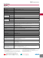
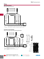
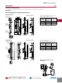
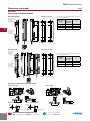
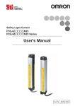
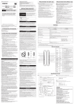
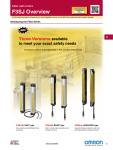
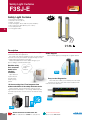
Safety Light Curtains
F3SJ-E
F3SJE
Rev. 9.11
Safety Light Curtains
D
•
•
•
•
•
•
•
Fast and easy installation
Resolution: 25 mm (1.01 in.)
Range: 7 m (23 ft.)
Protected heights: 185 to 1105 mm (7.28 to 43.50 in.)
Very compact size: 30 x 30 mm (1.18 x 1.18 in.)
Cross-talk prevention
3 m integrated cables
NEW!
Description
The EASY type safety light curtain is well suited for straightforward on/off detection applications.
By carefully selecting the available functions, we have reduced
man hours necessary for installation by approximately 1/2 when
compared with existing Omron STI models.
Reduced installation time means added savings to your
project’s budget, start with the EASY type.
Machine safety
first, narrowed
down to the
simplest
functions:
Global Support
Omron STI will support you through the our global network.
I only need
simple
functions
Global
Support
Upon detection
of personnel, the
machine stops.
Simple yet very
optimal.
Easy-to-view Diagnostics
1/2 the mounting time. Fixed response time
makes calculation of the safety distance easier.
These indicators enable you to intuitively know the status
and cause of any error. This allows faster installation while
reducing machine down time.
Reduced wiring, quick mount brackets and easy-to-view
alignment beams all add up to cost savings. Additionally, with
one fixed response time, it is now easier to calculate the safety
distance.
Easy-to-View
Diagnostics
mounting time
Mounting Time
D20
Existing
models
E type
Omron Scientific Technologies, Inc.
USA Tel. 1/888/510-4357 Canada Tel. 1/866/986-6766
For the Latest Information
On the Internet: www.sti.com
F3SJ-E
Safety Light Curtains
Specifications
Main Units
F3SJ-E££££P25
Sensor type
Type 4 safety light curtain
Setting tool connection *1
Parameter settings: Not available
Safety category
Safety purpose of category 4, 3, 2, 1, or B
Detection capability
Opaque objects 25 mm in diameter
Beam gap (P)
20 mm
Number of beams (n)
8 to 54
Protective height (PH)
185 to 1,105 mm
Lens diameter
Diameter 5 mm
Operating range *2
0.2 to 7 m
Response time
(under stable light
incident condition)
ON to OFF
15 ms max.
OFF to ON
70 ms max.
Startup waiting time
2 s max.
Power supply voltage (Vs)
Consumption current
(no load)
D
SELV/PELV 24 VDC±20% (ripple p-p 10% max.)
Emitter
Up to 22 beams: 41 mA max., 26 to 42 beams: 57 mA max., 46 to 54 beams: 63 mA max.
Receiver
Up to 22 beams: 42 mA max., 26 to 42 beams: 47 mA max., 46 to 54 beams: 51 mA max.
Light source (emitted wavelength)
Infrared LED (870 nm)
Effective aperture angle (EAA)
Based on IEC 61496-2. Within ±2.5° for both emitter and receiver when the detection distance is 3 m or over
Safety outputs (OSSD)
Two PNP transistor outputs, load current 200 mA max., residual voltage 2 V max. (except for voltage drop due
to cable extension), Leakage current 1 mA max., load inductance 2.2 H max. *3
Maximum capacity load 1 µF *4
Output operation mode
Safety output: On when receiving light
Input voltage
ON voltage: Vs-3 V to Vs *5
OFF voltage: 0 V to 1/2 Vs or open
Mutual interference prevention function
Mutual interference prevention algorithm prevents interference in up to 3 sets.
Test function
Self test (at power-ON and at power distribution)
External test (emission stop function by test input)
Protection circuit
Output short-circuit protection, and power supply reverse polarity protection
Ambient temperature
Operating: -10 to 55°C (non-freezing), Storage: -25 to 70°C
Ambient humidity
Operating: 35% to 85% (no condensation), Storage: 35% to 95% RH
Operating ambient light intensity
Incandescent lamp: 3,000 lx max., Sunlight: 10,000 lx max.
Insulation resistance
20 MΩ min. (at 500 VDC)
Dielectric strength
1,000 VAC 50/60 Hz, 1 min
Degree of protection
IP65 (IEC 60529)
Vibration resistance
Malfunction: 10 to 55 Hz, Multiple amplitude of 0.7 mm, 20 sweeps in X, Y, and Z directions
Shock resistance
Malfunction: 100 m/s2, 1,000 times each in X, Y, and Z directions
Pollution degree
Pollution degree 3 (IEC 60664-1)
Power cable
Connection method: Pull-out type, cable length 3 m
Number of wires: Emitter: 5 wires, receiver: 6 wires
Cable diameter: Dia. 6 mm
Allowable bending radius: R5 mm
Extension cable
30 m max. *6
Material
Case: Aluminum
Cap: ABS resin, PBT
Optical cover: PMMA resin (acrylic)
Cable: Oil resistant PVC
Weight (packed state)
Weight (g) = (protective height) x 2.6 + 800
Accessories
Test rod, User’s Manual (CD-ROM) *7
Applicable standards
IEC 61496-1, EN 61496-1 UL 61496-1, Type 4 ESPE (Electro-Sensitive Protective Equipment)
IEC 61496-2, CLC/TS 61496-2, UL 61496-2, Type 4 AOPD (Active Opto-electronic Protective Devices)
IEC 61508-1 to -3, EN 61508-1 to -3 SIL3
IEC 13849-1: 2006, EN ISO 13849-1: 2008 (PLe, Cat.4)
UL 508, UL 1998, CAN/CSA C22.2 No.14, CAN/CSA C22.2 No.0.8
*1.Do not use the Support Software and Setting Console for F3SJ-A.
Operation cannot be guaranteed.
*2.Use of the Spatter Protection Cover causes a 10% maximum sensing
distance attenuation.
*3.The load inductance is the maximum value when the safety output
frequently repeats ON and OFF. When you use the safety output at 4 Hz
or less, the usable load inductance becomes larger.
Omron Scientific Technologies, Inc.
USA Tel. 1/888/510-4357 Canada Tel. 1/866/986-6766
*4.These values must be taken into consideration when connecting
elements including a capacitive load such as capacitor.
*5.The Vs indicates a voltage value in your environment.
*6.To extend a cable of the F3SJ-E, refer to “Chapter 3 Wiring (Extension
Cable)” in the User’s Manual.
*7.Mounting brackets are sold separately.
For the Latest Information
On the Internet: www.sti.com
D21
F3SJ-E
Wiring
Basic Wiring Diagram
Emitter
Receiver
Wiring when using a test input line
S1
0 V (Blue)
Safety output 2 (White)
Safety output 1 (Black)
+24 V (Brown)
Test input (Black)
0 V (Blue)
D
+24 V (Brown)
(Gray) Communication line (+)
(Pink)
Communication line (−)
KM2
KM1
+24 VDC
0V
Power
supply
S1
: External test/lockout reset switch (connect to 0 V if a switch is not required)
KM1, KM2 : Safety relay with force-guided contact (G7SA) or magnetic contactor
Connection Circuit Examples
Emitter
Receiver
Wiring for single F3SJ-E application (category 4) (PNP Output)
+24 V
+24 V
KM1
+24 V
Feedback loop
KM2
(Gray) Communication line (+)
K1
K1
K2
K2
K3
K3
K1
K3
K2 K3
KM1
KM2
0 V (Blue)
Safety output 2 (White)
Safety output 1 (Black)
S2
+24 V (Brown)
+24 V (Brown)
Test input (Black)
0 V (Blue)
(Pink)
Communication line (−)
K1
K3
M
KM1
K2
KM2
Unblocked
Blocked
S1
K1
K2
K3
+24 VDC
Power
supply
0V
Reset switch
(S2)
External test switch /
lockout reset switch (S1)
Safety output
K3 N.C. contact
S1
S2
K1, K2, K3
KM1, KM2
M
: External test/lockout reset switch (connect to 0 V if a switch is not required)
: Reset switch
: Safety relay with force-guided contact (G7SA)
: Safety relay with force-guided contact (G7SA) or magnetic contactor
: 3-phase motor
K3 N.O. contact
K1,K2 N.C. contact
K1,K2 N.O. contact
KM1,KM2 N.C. contact
KM1,KM2 N.O. contact
D22
Omron Scientific Technologies, Inc.
USA Tel. 1/888/510-4357 Canada Tel. 1/866/986-6766
For the Latest Information
On the Internet: www.sti.com
Safety Light Curtains
F3SJ-E
Safety Light Curtains
Dimensions
(mm)
F3SJ-E/F3SJ-B Dimensions
The dimensions of the F3SJ-E and F3SJ-B are the same except for connector cables and cable leads.
Main Units
Mounting Top/Bottom and Intermediate Brackets
Backside mounting
Mounting screw holes
6.5
19
2-M8
4-M5
C (protective height): 4-digit number in the table
A = C + 69, B = C + 42.2
D = C - 45, E = See table below, P = 20
Protective
height
Number of
intermediate
brackets
E
185 to 1,105
0
—
1,185 to 1,345
1
C/2 max.
1,425 to 2,065
2
C/3 max.
18.3
2
dia.9
5.9
30
19
7.5
Top/Bottom Bracket
(F39-LJB1)
43
13
30
30
B
42
B
42
A
C
22
E
E
2-M5
E
2-M5
13.4
5.9
34.5
22.5
Top/Bottom
Bracket
(F39-LJB1)
B
C (Protective height)
D
53
42
5.5
P (beam gap)
22
C
30
22
7
Intermediate
Bracket
(F39-LJB2)
D
<M8 screw fixed>
45
<M5 screw fixed>
Side mounting
Mounting screw holes
19
46
30
2-M8
C (protective height): 4-digit number in the table
A = C + 69, B = C + 42.2
D = C - 45, E = See table below, P = 20
34.5
4-M5
5.9
6.5
7.5
30
19
18.3
Top/Bottom dia.9
Bracket
(F39-LJB1)
7
185 to 1,105
0
—
1
C/2 max.
1,425 to 2,065
2
C/3 max.
B
C
42
B
C
42
E
D
C (Protective height)
E
2-M5
E
34
22
2-M5
E
53
42
5.5
B
A
22
Number of
intermediate
brackets
1,185 to 1,345
30
Intermediate
Bracket
(F39-LJB2)
Protective
height
42
Top/Bottom
Bracket
(F39-LJB1)
13.4
12
5.9
22.5
16
<M5 screw fixed>
<M8 screw fixed>
Dimensions of top/bottom bracket
for F39-LJB1
dia.9
19
6.5
16
30
Omron Scientific Technologies, Inc.
USA Tel. 1/888/510-4357 Canada Tel. 1/866/986-6766
For the Latest Information
On the Internet: www.sti.com
2
43
4.3
7.5
18.3
34.5
45
Material : Stainless
D23
F3SJ-E
Safety Light Curtains
Dimensions (continued)
(mm)
Main Units
When Using Quick Mount Brackets
Backside mounting
Mounting screw holes
43
30
C (protective height): 4-digit number in the table
F = See the table below.
F
Number of
intermediate
brackets
F
185 to 1,105
2
555 mm max.
1,185 to 1,585
3
555 mm max.
1,665 to 2,065
4
555 mm max.
32.1
<M6 screw fixed>
Side mounting
Protective
height
C
32.1
F
32.1
275 max
15
2-M8
C
Quick Mount Bracket
(F39-LJB3-M6 or
F39-LJB3-M8)
F
C (Protective height)
D
2-M6
32.1
30
275 max
Quick Mount Bracket
(F39-LJB3-M6 or
F39-LJB3-M8)
<M8 screw fixed>
Mounting screw holes
45
33
F
32.1
C (protective height): 4-digit number in the table
F = See the table below.
Protective
height
Number of
intermediate
brackets
F
185 to 1,105
2
555 mm max.
1,185 to 1,585
3
555 mm max.
1,665 to 2,065
4
555 mm max.
32.1
C
2-M8
32.1
275 max
Quick Mount Bracket
(F39-LJB3-M6 or
F39-LJB3-M8)
F
F
C (Protective height)
2-M6
C
275 max
30
32.1
16
Quick Mount Bracket
(F39-LJB3-M6 or
F39-LJB3-M8)
3
12
<M6 screw fixed> <M8 screw fixed>
Dimensions of quick mount bracket for F39-LJB3
Backside mounting
Side mounting
80
(32.1)
80
(32.1)
dia.22
(32.1)
30
dia.22
dia.22
15
15
(32.1)
45
30
45
dia.22
1.5
8
22
22
D24
53
dia.8.2
dia.6.2
dia.17
Material : Stainless
1.5
8
Material : Stainless
Omron Scientific Technologies, Inc.
USA Tel. 1/888/510-4357 Canada Tel. 1/866/986-6766
For the Latest Information
On the Internet: www.sti.com
(16)
Quick mount M8 bracket
8
Material : Zinc die-cast
Quick mount M6 bracket
dia.13
(46)
8
30
53
(13)
(35.7)
(31.5)
26
Material : Zinc die-cast
F3SJ-E
Safety Light Curtains
Ordering
Main Units
Safety Light Curtains
Model
Application
Detection capability
Beam gap
Operating range
Protective height
(mm)
PNP output
Hand protection
Dia. 25 mm
20 mm
0.2 to 7 m
185 to 1,105
F3SJ-E££££P25
Safety Light Curtain Model List
Please contact our sales representatives.
F3SJ-E Series (20 mm pitch)
Model
Number of beams
D
Protective height
[mm] *
F3SJ-E0185P25
8
185
F3SJ-E0225P25
10
225
F3SJ-E0305P25
14
305
F3SJ-E0385P25
18
385
F3SJ-E0465P25
22
465
F3SJ-E0545P25
26
545
F3SJ-E0625P25
30
625
F3SJ-E0705P25
34
705
F3SJ-E0785P25
38
785
F3SJ-E0865P25
42
865
F3SJ-E0945P25
46
945
F3SJ-E1025P25
50
1,025
F3SJ-E1105P25
54
1,105
= Highlighted Rapid Delivery products are
available for shipment today or within THREE days.
*Protective height (mm) = Total sensor length
Accessories (sold separately)
Relays with Forcibly Guided Contacts
Type
Appearance
G7SA Relays with
Forcibly Guided Contacts
G7S-£-E Relays with
Forcibly Guided Contacts
Specifications
Model
• Nodes: 4
• Contact type: 2A2B
• Rated switch load:
250 VAC 6A, 30 VDC 6A
G7SA-2A2B
• Nodes: 4
• Contact type: 3NO+1NC
• Rated switch load:
250 VAC 6A, 30 VDC 6A
G7SA-3A1B
• Nodes: 6
• Contact type: 4NO+2NC
• Rated switch load:
250 VAC 10 A, 30 VDC 10 A
G7S-4A2B-E
• Nodes: 6
• Contact type: 3NO+3NC
• Rated switch load:
250 VAC 10 A, 30 VDC 10 A
G7S-3A3B-E
Remarks
✎
For information on the
G7SA see page H3 or
visit www.sti.com.
✎
For information on the
G7S-£-E see page H8
or visit www.sti.com.
Laser Pointer
Appearance
Output
Model
Laser Pointer for F3SJ
F39-PTJ
(Continued on next page)
Omron Scientific Technologies, Inc.
USA Tel. 1/888/510-4357 Canada Tel. 1/866/986-6766
For the Latest Information
On the Internet: www.sti.com
D25
F3SJ-E
Safety Light Curtains
Ordering (continued)
Accessories (sold separately) (continued)
Sensor Mounting Bracket (sold separately)
Appearance
Specifications
Model
Application
Remarks
Top/bottom bracket for F3SJ-E/B
2 for the emitter,
2 for the receiver,
total of 4 per set
F39-LJB2 *1 *2
In combination use with top/bottom
bracket for F3SJ-E/B
Can be used as free-location
bracket.
1 set with 2 pieces
F39-LJB3-M6 *1
Quick mount bracket for F3SJ-E/B
Supports M6 slide nut for aluminum
frame.
Top/bottom bracket
F39-LJB1
D
Intermediate bracket
Quick mount bracket
1 set with 2 pieces
F39-LJB3-M8 *2
M6 slide nut
Quick mount bracket for F3SJ-E/B
Supports M8 slide nut for aluminum
frame.
F39-LJB3-M6K *1
Spare slide nut for use with Quick
mount bracket.
M8 slide nut
F39-LJB3-M8K *2
Compatible mounting bracket
F39-LJB4
Mounting bracket used when
replacing existing area sensors
(F3SJ-A or F3SN) with the
F3SJ-E/B.
Note: All the sensor mounting brackets for the F3SJ-E are sold separately.
*1. Combining F39-LJB2 and F39-LJB3-M6K makes F39-LJB3-M6.
*2. Combining F39-LJB2 and F39-LJB3-M8K makes F39-LJB3-M8.
information on Resource
✎ For
Modules, see page D59.
D26
information on safety light
✎ For
curtain accessories, see page D74.
= Highlighted Rapid Delivery products are available for shipment today or within THREE days.
Omron Scientific Technologies, Inc.
USA Tel. 1/888/510-4357 Canada Tel. 1/866/986-6766
For the Latest Information
On the Internet: www.sti.com
Hexagon socket head
cap screws (M6 x 10)
are included.
Hexagon socket head
cap screws (M8 x 14)
are included.
2 for the emitter,
2 for the receiver,
total of 4 per set