1
'г
""\ ±
ЭЁШҐПЁЁЕЗЁНЕЪЕІ
fii'l'|fliEfl§E§EflE£E|
SUZHDU
ЅПІІ-[ОП СІТУ
CITY KUHTENG
КШЧТЕНС ЕЬЕСТКОІЧІС
ELECTRDNIC C11.
СО.. LTD
ЬТІ)
\I
›l
℉℉℉℉℉℉℉℉℉℉℉℉℉℉℉℉℉℉℉℉℉℉℉℉℉℉℉℉℉℉℉℉℉℉℉℉℉℉℉℉℉℉℉℉℉℉User Manual
KT-LCD3 eBike Special Meter
WWW.SZKTDZ.COM
ELECTRIC BICYCLE METER KT—LCD3 Product User Manual
Contents
Preface……………………………………………………………………………..………. 4
Outlook and Size…………………………………………………………………………... 4
MeterDimension……………………………………………………………………… 4
Button Box Dimension……………………………………………………………….. 4
Main Material and Color………………………………………………….………...... 5
Wiring Schematic……………………………………………………………….……. 5
Installation Instruction……………………………………………………………….…….. 5
Φ 31.8 handlebar diameters install icon………………………………………..….… 5
Φ 22.2 handlebar diameters install icon……………………………………….….…. 5
Physical installation icon............................................................................................. 6
Function Overview……………………………………………………………………..….. 6
Display Content…………………………………………………………………….….…... 6
Button Definition…………………………………………………………………….….…. 7
Normal Operation………………………………………………………………………...... 7
On/Off…………………………………………………………………………........... 7
Display Interface………………………………………………………….….……..... 8
Display 1………………………………………………………………..……...... 8
Display 2……………………………………………………………………...... 9
Display 3……………………………………………………………..……….... 10
PAS Ratio (or Handlebar) Gear Switch……………………………….……………. 11
Push Function…………………………………………………………..…………… 11
Cruise Function…………………………………………………………………...… 12
Turn On/Off Backlight…………………………………………………….………... 12
Battery Capacity Indicator…………………………………………..…………….… 13
Motor Power and Temperature ................................................................................... 13
Environment Temperature…………………………………………………………... 14
Single Data Clearing……………………………………………………………….... 15
-1-
ELECTRIC BICYCLE METER KT—LCD3 Product User Manual
Automatic Prompt Interface……………………………………………………..….. 15
Error Code Display…………………………………………………….…........ 15
Motor Operating Temperature Alarm……………………………………......... 15
User Project Setting……………………………………………………………………..... 16
General Project Setting…………………………………………………………………… 16
Maximum Trip Speed………………………………………………………….......... 16
Wheel Diameter…………………………………………………………………..…. 17
Metric and Imperial Units…………………………………………………………... 18
Exit General Project Setting……………………………………………………….... 18
P Parameter Setting……………………………………………………………….…….... 19
P1 Motor Characteristic Parameter Setting Mode ...................................................... 19
P2 Wheel Speed Pulse Signal Setting Mode .............................................................. 19
P3 Power Assist Control Mode .................................................................................. 20
P4 Handlebar Startup Mode ....................................................................................... 21
P5 Power Monitoring Mode ....................................................................................... 21
Exit P Parameter Setting ............................................................................................. 22
C Parameter Setting ............................................................................................................ 23
C1 Power Assist Sensor and Parameter Selection Mode ........................................... 23
C2 Motor Phase Classification Coding Mode ............................................................ 23
C3 Power Assist Ratio Gear Initialization Mode........................................................ 24
C4 Handlebar Function Setting Mode ........................................................................ 25
C5 Controller Maximum Current Adjustment Mode ................................................. 26
C6 Backlight Brightness Adjustment Mode ............................................................... 27
C7 Cruise Function Setting Mode .............................................................................. 27
C8 Motor Operating Temperature Display Mode ...................................................... 28
C9 Power-on Password Setting Mode ........................................................................ 29
C10 Automatic Restore Default Setting Mode ........................................................... 30
C11 Attribute Selection Mode .................................................................................... 31
C12 Controller Minimum Voltage Adjustment Mode ............................................... 32
Exit C Parameter Setting............................................................................................. 33
-2-
ELECTRIC BICYCLE METER KT—LCD3 Product User Manual
Parameter Copy .................................................................................................................. 33
User Setting Note ............................................................................................................... 35
Version Information……………………………………………………………………… 35
-3-
ELECTRIC BICYCLE METER KT—LCD3 Product User Manual
Preface
The illustrated manual will help you understand and be familiar with the meter
function, guiding you on how to operate the meter, how to set the project parameters, how
to achieve the best match of the three as motor, controller and meter to improve electronic
control performance of the electric motor. This manual covers installation, operation,
parameter setting of the meter and how to use it properly, which help you resolve the
problems appeared in practical use.
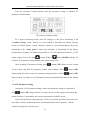
Outlook and Size
○ Meter Dimension
~;2З
96
96
14
|
1% гг 0 На
3 из
О ОТ
131!
вввв.в:нв:с:Ф,
Ё3
аіїї
сп
Meter Dimension
_
86
56
_
72
ї
Эд
@515O,
1
\
-А58
Dual Bracket Mounting Dimension
○ Button Box Dimension
їЄ>,З
6.3
1
11
83
E3
(DEE
Ф22
LO
‘<1’
*1
-4-
ELECTRIC BICYCLE METER KT—LCD3 Product User Manual
○ Main Material and Color
PC material is mainly used for KT-LCD3 meter and button box housing, and the
housing color is dark gray or white.
○ Wiring Schematic
l
зєу
нед
exp
с\1э
Black
в1а<:ъ< Em
Ш: ||
'r
Соп'Ёго1
Coifiiol В1ъ1е
gifie
Ва_Іа1
Datal
Вдтд2
D3152
Ё
/^
Ё"
Egg;
K:}v
Сгееп
Green їёч
Уе11ош
YE‘-110W ЁІЁЮ
l:l"'-l
.
-\
“Ё
I
«
Ітнідшіінн
Illfifilll "ll"
В1Ѕр1аУ
Display
~11
»
.
:
У
%
%
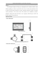
Installation Instruction
The meter body and button box are mounted on the handlebars of the electric vehicle,
adjusting perspective. In the case that the vehicle is power off, the meter connectors are in
plug connection to corresponding controller connectors. Turn on the power, electric
vehicle and meter will be under normal operation, the meter installation is finished. The
protection film on meter display panel should be torn.
○ Φ 31.8 handlebar diameters install icon
І
\
Ш
EB
Ё
Ё
lill
Ё
W
lLLi
ШШ
ЬаЪега1 View
Уіеш
Lateral
Меїег
Вцаї Вгасйет
Meter апё
and Dual
Bracket Уіеш
View
○ Φ 22.2 handlebar diameters install icon
ll
the encired
rubber їіеісіесї
fielded рапеі
panel із
is
(Не
епсігеб гиЬЬег
optional Ф
<l>22.
or<1>
ор±іопаІ
22. 2 от
Ф 25. 4
6%
Єёд
%ў
'l
Іl
їl
N
Ш
E
Шшпfiimnnnlшшпl
Ща
Ё
U
Ш
the епсігесі
encired гиІ:›Ьег
rubber Тіеісіесі
fielded рапеі
panel
(Не
Lateral Уіет
View
ЬаІега1
K
Ё
ЄЩ
U
Ш
the епсігесі
encired гиызегііеісіесі
rubber fielded рапеі
panel
(Не
Meter апд
and Виа1
Dual Вгасйег
Bracket Уіеш
View
Метег
-5-
ELECTRIC BICYCLE METER KT—LCD3 Product User Manual
○ Physical installation icon
7%
find“PU
V
‘L
mm‘H_
“FL
_“‘_H___H_
M_HU_
гыІ Д
І дм30> ЦМп
‘_‘_
|‘_h‘
‘H
W!‘
‘U”__._ _’_, __'an_ r_
Wm”;
M
Ч: Й7"
ЙЫ`
‘ _.€>’
_
_‘0’_'._
._.‘
др
Function Overview
KT-LCD3 meter provide you with a variety of functions such as vehicle controls and
vehicle status digitized displays to meet the trip demands.
◇ Trip time display (with displays of a single trip time (TM) and total trip time (TTM));
◇ Trip speed display (with displays of real-time speed (Km/H or MPH) and a single
maximum speed (MXS) and a single average speed (AVS));
◇ Trip distance display (with displays of a single trip distance (DST) and total trip
distance (ODO));
◇ Power assistant ratio (or handlebar) gear (ASSIST) switch;
◇ 6Km/H power assistant push (
) function;
◇ Cruise function (CRUISE);
◇ Battery capacity indicator (
);
◇ Real-time battery voltage (VOL) display;
◇ Motor power and temperature (MOTOR) display;
◇ Brake display (
);
◇ Turn on backlighting and lights (
);
◇ Environment temperature (℃ or ℃) display;
◇ Data clearing;
◇ Fault code display;
◇ User parameter setting
℉24V, 36V, 48V supply voltage can automatic identification and be compatible℉
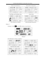
Display Content
The display content is shown as follow.
-6-
ELECTRIC BICYCLE METER KT—LCD3 Product User Manual
Вайегу Capacity
Сарасіїу Backlights
Вас1<1і3І1ІЅ and
апсї
Battery
Ішїісаюг
Indicator
6Кш/Н Power
Рош/ег Assist
Аззізг
6Km/H
\/е11іс1е
Ѕреесї
Vehicle Speed
Неас11і;11гз Ѕташзїгаке
Ѕгашз\ Візріау
H{<flights
Status€rake Status\DiSD1E1Y
Цї¦ё››о«
АЅЅІЅІ
Ё
ф
Кпппіпз соиптег
РНЅІ1 Рппстіоп
/ Running
Conn? Push
Function
З:2ВП^м
і-':\\/3
О М›іЅ
ф
'
'
Ю Ц Ц: Дит, Й%|ь1к“ъш'^(;
её/Ш
/
/
Power
Ratio Gear
Р0\Х/Єг Assist
АЅЅіЅІ Кайо
Єеаг
and
апсї Cruise
Сгиізе Function
Рипсїіоп
Trip
Тгір Distance
Візгапсе or
от Real-time
КЄа1-Іі1'І1Є
Battery
Ваїгегу Voltage
\7о1Іа,<;е
\
Environment Тетрегашге
Temperature
ЁШ/іІ'0І1шЄпІ
Motor
Operation Power
or
Моїог Орегаїіоп
Рош/ет ог
Моїог Rlllming
КшшіпЁ Temperature
Тетрегашге
MOW"
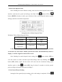
Button Definition
KT-LCD3 meter adopts the structural form with part design between the main part
and operating buttons.
There are three keys on the operating panel of button box, which are icons of
button (alt text UP),
button (alt text SW) and
(alt text DOWN).
СІGEDЕІ
Button Box and Operating Panel
Normal Operation
○ On/Off
Hold
[
1
at
button (SW) long, the meter is powered on and into normal operation, and
it provides the controller with power supply. Under normal operating status, hold
at
button (SW) long, the meter is powered off, meanwhile to shutdown the power supply of
controllers. When the vehicle is stopped and without any button operation on the
meter for five minutes, the meter will automatically shut down, and the power supply
of the electric vehicle will be powered off. In power off mode, the power consumption of
the meter and controller is zero.
-7-
ELECTRIC BICYCLE METER KT—LCD3 Product User Manual
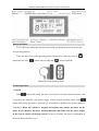
○ Display Interface
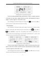
Display 1
The meter is startup to enter display 1.
§
ш__
%
пи “Ц пи лмТ
мины _'Іы :0“атмI221E3 Пит“интим
Ш-
ASS I ST
I" »—
_
—
0.1
T
,
_
—
:
l 0.1 u u
E21UI23
‘
пиВ пи пи пт
‘III?’
,
‘l
И
\\
TM
TM
in PH 4;» all
° Knv1{rWL MOTOR rfwie
ча
__<В_Ё
Ѕ
ЕТ
Ь
1
Q
P9!
H
‘lnli>lL Q
С
_`_
О
ii-Ii til
ciefi
\\.
Display 1
The followings are shown on display 1.
\\
7";
w
TE"
u
W
l l ll “T”
l l ll
l l
r.
l
rrni
rel
llwrl ll 'l
Y/
\Y
,
_.,l
/Ai“;/>~
MFY31
>>>f<Q:;e>
l l
НВ
\
//
l
\/ vile ri_r, vile
l‘ l~‘§~%’> »‘%~i*~ l~“=?’~
l l l l £1
,l l l
an
l l
l l
Z) ’F
Pall 7 T 7 l‘j~w”llli7~lr*lllrrjl
lwil lrril in il l /l l1»::;<\
lA:7Wl"/V} l:;z;;<‘
E’/l
<*I1>:' ;<:§>:' “>¢:%< >i:;>;\ i>si:;>;f by
l ll l ‘*W
~ Fl lH===E Tl/”l;\L ll/<)Tlilll¢l71l\llll‘l#LLl~ l7Ll41\l Mno lll
~;F
‘A <1’;
\‘
O
l l
l
,\;;,
[
7
‘
J
J‘
\
K 7* (
» l
“\,//’;’/
'V\
/y llll.,.;>’l
4
lll?’l,i
‘kl
;y t e I
Tl fllJfll’@lT'lT,lF¥‘
/Y
m
B.g:JUU/U=U
‘KtA
Ul ~:
Q
‘W? (
U
”“E]]"C»‘~
lg,
M, Ii
W ,,
/T,
\ ,
‘
l
D
l tg
l‘J! xjyzz,
l l ll’ wjid
l
l L JF
T‘
T}
l»»,;;;;,,‘
'5
Mun
7_
l ll l’
mm ll l Ll'l Ll l lgllifg
e‘lil”<iJlL lLl, ll l_l.l ll ~l,l_lr_lllV,»_,,l
4%‘ l,Llr;l
or Be
[l3FQll:li H
’,
l
ll
,
,
W A
QWZIT
t¥fi!:\
rllrlpvllégll
чдь И..Ґ:
ВМ
__-Ш
i T U
,/
Ci:
/
‘\1t~_--If‘
l
l
’:
ii?‘
Et‘
ll‘
t\С/
\\Ё
//{
J.
\
"Kn
A
,~'A
V’
\§
/J’
'& »
7”
>1
‘Vri:E.;:y
'5
/‘l
‘\ \
ilinrnn" "F Wlllll
1*
, E
v,
l/:§\‘_i,¢//
‘
A
//
ll ml turlril lal
LJl@e":nnnnnn1
nine
“ll ° Km/H it l “
l
Uiugyflwngg
'
"',_l. llll_l\ll’utl_rl,\ lp;,l_tp,l Er»-oiri
l/
Power Assist Ratio Gear (ASSIST)
И
"K
f
:<::;¢:,
l,¢l_l,€ll€;E§ll,l_lt,l liglitgl UQIW
ll
rc_»l
l l
lJ l
,1
(l l
_*щ
;;i:;:~: ?>1i‘:j>: i:;;;;
iw;e
H
W
u
E1
l
lnafiemmfififimflfiw
rrln
“ll \%ri¢*ie<
@;lM%@
nnnnnnn Q
l l l_
T
J
~
ti lrinii l ojlji,/il liinil
All n;ln;ln n
fi\;lfl,_~*=;¢>_>i
fil
Single Trip Time (TM) Display
W p ‘l ‘l ll ll ll
_/‘~\_\“~_,wji,
ll
it
’;i7l"]
5’pl l l
M
(Q/lg’ ll /ll; llll lllij
u we
lefilawmflfifiwflim
TTM
4%“
»
ll
Ll ,l
V,/'=_
//
Battery Capacity Indicator
M it H
l l
“,~=,‘
3T
\\
l
ll ll
l l
4
l
l
>1.
ASSIST
l
‘l,'
\\
° n;u;n rrln
K
l, r:.
пи___:
ди TM
Ш
\\
M,
-X
l,»,
*’&~<é,;:/7”‘ @l
(H ‘/~€,,¢.K
{Man
l_l
‘G
Real-time Trip Speed (Km/H)
f l
7T
E‘/'e~lt\)
J}
O l\l*[,';l iim}
і
/Tiliyi
il“g\i'L-:lll1:1lliK‘;;)l\Tl_\
/
‘l
._
l
‘l
,,\
l
_
fl
l_
lllllll‘
l l
l l- in?~H
e l ‘era
Т
DST
/~
T
f:;;:;§ j::§:,;}:f V315:
Ll
ll nr l l lT
” * "
/El
ll lx/‘,_1\U l i/l_iU L7l_L,,
l l l l l l l l l l
li’
ІІ
Gll U
,
_t
,~;l~l\‘ l /l l_l TLllF€ F n
ВВ
.5-1' D;/I
Ш
:
l
*3
l~J
i
K
‘l
l
l l
l ll
~;F
\\
‘A <1’;
l
l Il
>1.
T
l
‘l
l
’
l
l
I
l
l
l l l l
l l l l l l
l »"?*1>a,
~47 l
K
‘l l
l
l\ pl
l
l l_
ll: l " ;
I l l l
rows vi,
,,l
"“*l'"y
Ll /’*»>s\V~‘
l,‘ Ll
r
WPH
TLl
T7 ,7
T l
1 v
‘l
‘v I
_
llllll‘1lTll‘llR
/T\
fl
'?
I
i
l
I
I
)1
'rl—'\_
MF lulllltlitlé
ll» l.:,l)L
>
~ ~
~
V
_JlJLl
7
I J
<_
,
~:i~}"‘\
<I l til\
re"
7
r A:
t
rrn
|\
(éblliid H
L‘
MOTOR a F w
‘
0
a
ll
i,
ї
TM
TTM
чат паи
i
:
\‘
ЧК
u on-tglniazl
1
6Km/H Power Assist Function
> -/:\ ,-;
,>
lj' l]llpj*_l§/l
(:1 lV-as‘_j}l:lV;,>\4llV\j_l\:¢,l TM
4
l
O Km/H
M?H
liil
_
crow:/,1
\
Ж
f
4
l A
iJ
l 11
xli C
,l
l
n
,_r l,, \ it
r
“Ul*”CWW“DWU1WFrjWTMQPn
l_l;:;FlU U
Single Trip Distance
iii
iii
lilg
ll
l
_
Ll»
rra ll~
Й
@[~\_§
l
’
ii
l_l
К̀
\\
an
E“
lmrltg T” H “TIT
7
ft
‘ll
Ll/
“‘](l' L‘
l
l
pi
l l
<6
J
it
l l l l l ll
ll
/1
-8-
\\
/\E;\i";El“l
l
l
l
r l
1‘
*7»
‘l"iil:¥>‘\_i:;?":
ll ll
,
l T lllll‘
l,"»
l
~\ l
~>
I
1‘
y
(L
E
W ‘~‘~;al»‘L.
ll
If
,.~
;:\r\\‘ ll:
via
_l
,/H
‘l l l ‘Cw w 1>
,, , P.
ll I ‘ Ff] ‘ J
i W
Hlimilfirul
> M W ii
'
/
»:r\én,;:~‘ (\é,,- ‘l;__,,;~ rsli,»
l l lllll‘llllll lill
llll l
»\__M,;>,
f
ilinrlon -F l l l
‘iii
1:
I D
ll Mil
W
/AM»
LA» lnrll ,»/Ll1\ll l/¢lT‘li_.l“ l '{iJ:\ l mi ll
ct: <7: its ‘J lit?
[
lizjsi ll;l7l;\,l
‘:<I;>;’ legal
Ll711 llnlrl
Y
tow
l
rr t;l -\
__: F
l1_
.
(l
U QC
4
ELECTRIC BICYCLE METER KT—LCD3 Product User Manual
ШЁ4
Motor Operation Power
/И
“K
____ . {
=
:
l
(\
=.
I
/T ‘Tr
l
ll l Tl
l
l
l
l
l
I
l
l l
r
ITTTl»TII*I ,.I
l
l
l
ll'j7fi?i§i:*i;¢
ll Wm“;
Ii
filing“
і
\‘
TTM
1 Tr:
T l:1i~
0’ ll);
lul L4
‘Zi
\_l
TR; a‘~
M
l
IA1;\€';T,
l
H
/II
l
l
I
Il
l
l
l l Il l
T
ll’~l"‘lol
ti>
@§E§,T
l
lagtl/l al~grr;l lllit \;iTllll ll ll ll llll I Dll
‘l l<Ll
_ll_lll_l‘
\ll@L lbl
~r~_o>l@ lo“ Um l~l l
l ~l
_
l
Tl l
l
rift»
_.e.
I»*I]4I;>%I
U‘lifl}i¥1;§§>
I B
I
l
l/[H
l
’//‘l ll
l
'7
l
I
F
@
‘CK-
/I
‘ l
JF
lolnlli;
T— 1
liCjF:‘Ll
It l fl ,:\
/
//
n
l1?5Ll:T/lll:£lll71L\‘l
lnll nl ll
T"
" TT :
_Ц
_
Lll ‘ l
‘
l/x /!\l¥II,_,l‘(\l
1:
in
W
l l
I
l
l
I
r
l_>_\,l
/\,¢
ll//ll
1;
S4,,
I
l
r’ l
l/rill
NIV‘ll
n
~"
"Tl?
l'i\
l— \‘l/'
\/ ‘J\7
V
l"ii
>»i<
Te
,
fl/
'
J" l"Ki
l I
ex
T5;
3.
n
If
\lIIllIr
;»T E
(I, I, A
l
_l ll
T
ll T
REF‘
\і/
~\\
rr U1
3 ii
/I
CQJ
Cl lTull?J
lTu
.
Ml ‘<~ =2» H 12,;
\=»
L,-\TI.\L,lQL,]
,
l
V
I we
I
V
l
T/“
rii-ii »lTvll;TLliIl lpntl
Brake Status
I
I
/‘~:\
*
KY1 ll
kl Fl
lo
//
l l l .
.
l
I
I
I
—~
T
II, -,I
’ l l/l
,T.
l
,1,I ,¢I_,>,I ,tI_,>,I
T,
nll
ttn
К га _.:
Ю
III
ljil
II,, \ I
.l l
,
/ I
T7“
If Il
tr
n
D
\'
‘-iiI¢"I
/И
W H ~’~l° lllllnlrl ale lll we
,>
,
III‘II\LII_IT7II:I_III,;Tl’|%]
;> l
”/
ll ll L l lTl_r l l l_Ll
I,
Kr
//
TTlillil
lTil:lTTil l l_l §;l i ni;l it Mli‘ “ lnn T‘ll
i‘ "Fl
Tl T" llllT"lll/%.l
I3
ЅЕ
QRU | SE
l
I
:5
T T T T : “
2
\\
\і/
\“
T K
\'
w7,L
lTLl lll_lLl ll l;ll;Tl_ll
\l'
A
Backlights and Headlights Status
/И
I‘//’
l
Tl l
I
rrln
A II A
u T
-,ш
\\
TM
lo‘
_
\Qi1-J k/l
`і/
Од
0
llT Q up Q
\T;:,
\;T/>4
l\,;I'/l'7“l;:\,/"
/A
7 TT»
,/\
/
tr
,/
._
T
l
Environment Temperature
\і/
a_T
I: III
\/
_ llll
l ll MTFH l/ll MOTOR F lll°c
~ ,=
?\
<?\
n ll
Al-
E
\\
//
Cruise Function (CRUISE)
Motor Running Temperature
Display 2
In display 1, hold
button (SW) shortly to enter display 2.
[
T
at
ЙЦ НЦ НЦ лм ПЦ
V114:
,3G Q1_ 5;!
Ю--+
р.'_ _..Ь I’!“атмAV§
АХумМ3Ѕ1
__| БМ ЗА
lfi jl
9 l" lgl l"l E3354
-J ga
M H
MOTOR ale l l °c
//
:_\
§Il’“‘=»I l/ITr1":*;I»
ІІ чі
__
_О
ы`О T
I
\\м
<1‘ 7 -
O
‘CI
e
<1__
TM
T TM
IfQ 0
I
ї
\\
птЛТїм
,7/
0____\_ В ОТЬ
’‘
u
‘llll
пи пи пи пи
rnnnrft
-a-‘e>TTJ
ПШ
Атт
il__ l Tl
чаНа
__С
l
Eu;“EC
lil
//
\\
Display 2
The followings are shown on display 2:
\і/
N“
/Ні
2| rm
Sf
~;f7”
L
is
/T//\\
\;~fil71’ l
ll
-.
/‘Tet;
L
Jr“/=‘~u\\!I/ti:/15]
,/
I ,' ‘,1’
*7 \I
T;
i
I;;l\
БМ
і_
‘xv/4//’;l’Tli1i_;‘
l
l
.l
I11ZIiP1'
//l F l
kg;
B
l /'~\
iIsfi;T¥I'
or
,
,
K
la
lll>~l:§1~.tll
li
n
finial nil
H Q7‘
eT
IITQ<1ii;“
‘;r;:T
TI
l Ll Tl
/
//\
\//
~
U
\\
I:Il
l *~,
T
~n »
l
11:1
l\_f5~
Tl“
liéif
l‘:<'fl
‘:1!
T521’
_ 5
e fa?
:
‘Tl 3;’,
l
T
В̀Tl
Tl
l
l Il
IT I
I
l
4
\\
\і/
\\
“K
/
.<_
_
ll ll
\
nllulTlulR are n
4:6] lll
ll Pl
lav \
l5
8 ВАCl n n :»léi;l
ІІ
` К
И`
l7§l,,':\
lg
`_
lrL
e _ Ql Kmт r Til lTj;Tl:l;Tl l
T“lil lJ@lLl1:”Tl“>ll1?’erT 5..
U:.0
Total Trip Distance (ODO)
\і/
rln
Jre;Tl
[Tl
U
TTlillil
iii
iii
l
l
l.
4%
l
\,~ ,
ll,‘
l
lsll
lr
ll’
lJjwl
i:l‘—l?l/):;_::;I
l l\l :l4/l l‘T>;‘ml
l l_l ll lill TM
‘;::l"§:i
_I;~=:j _ :»:_<>i l_lIIIIl T I
II‘
til
T;
l /
ll
ITIIFM U
_
//
\\
-9-
E
I,
l I
lqflt,
T, '?\l?,<2,;
\\;/VQ/J;-N ,
/wt
il
l
,
T/‘rm
, En
t T1
<:>
<\
llll ll
_lj#.u \Ul'/"P;/l
l\;:
fa
II
lllIll,I_
ll
/
TM
I 4
I
T
ll lti I'MIQ!
l;’~l1i, MOTOR ‘re °c
I
\.l lgrxul
II\I
Ilfr Il
l l
lT\Ill(,,l tIll,LtLl ‘@”l/Q
X
l\“I;*Ir’
’ l ' ’ ‘ l L
r ML ll l ll Ll lllIlIII,
tl l,Tl t_l
l
щ \_Мщ
34%
I;:;I_It.»:I
/И
1'
llnlrnn
l
rln
М МlTetl
l,4,
e»sTTl_Ган
4 TYT
II___IIIII
»»,
H
0 ,<M,fqH|
I
ttn
В
I
I I
l
u
“T
.. __T
I
l
/‘\-7!"
Total Trip Time (TTM)
_.:
l
04.1
I
I
it
"О
l l О°‘Z%
T
ale
И
//
,,TjT’IIIf3
W I_Il_IIII
\__
T lg’
rr ze TF lLl
‘lill’l T
4 l‘lil""l*l'
4 l:
_
t
T
Il
l
ll,l_l all "La
\;
l
l'jl~,¢\
>1i:I;>rf if§;;%1T I:III:I
<
_I
J
l Tl
I
are llll
.:=l \
\\
T/111555?
'VVVVV;/ £/ / / /y/ IIIIIIT;;;T
rr
I
Мд_il l'll‘lrl
» ll
iisijiéri i1si:;>1f
V lrlrtlal
* Ь..
Ll lll l l-T lTLlll‘ rm
_
_l 'Ь
_
‘ll@L
u
u
l-
l:~l *l ~.l
ll tnu
é
l
I iii’\ II
/ V;/ / / /V/ /y/
l
Ili\*Ix7Ir”Il
/ \\{
‘
l T§Ll;l‘
l
.\
//
_
l l l * l l ,l l ll ll
l lI lnlela
I :1’ I
\і/
і
'5'?‘can
/1»
§.lTi»* *‘~l‘:\;~;ill“~
l
“
‘I
fr.
I7”
I
D
'\
/I
at
l
_
IT
lsqi/j;
@
A
//
\‘
Tllylllj,l‘L
F ‘W
/5
if/G‘:~ »'‘
ll
I M5"
ll ll_tl Dt~>Tru*u
Pl
.,
tr
.£
;.~
l_ll,,,l_l,lT(II;TTl_l&Il
./
r,‘
)
\_
ELECTRIC BICYCLE METER KT—LCD3 Product User Manual
Single Average Speed (AVS)
Motor Operating Temperature
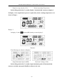
In the riding mode after 5 seconds, display 2 automatically returns to display 1.℉
In display 1, the original motor power is replaced by motor running temperature as is
shown in Figure.
%
//
Ё
С
7Ы*
7Ы.
Ѕ
\-\
i i TM
T T rrllll
6:;czlcm
czlczl
“Ц пи Вы
КБ ЗАЮ
-J -J ill i i, MOTOR‘-"1l.~.l
_.: ча
пи ___”ти пиВ
Ю-,
Ю-МН
ASS I ST
la
Q
V‘
’
'
lliliillllil
l _
,__
nil
'
Q
Кт
E-J
51.!
-_F
Va; C5’
ОС
ll;
lplg;
z3
:
~‘4,*4_,
\_\
Щ
Display 3
In display 2, hold
button (SW) shortly to enter display 3.
[
T
at
И
iii fee _
lil l
lI
lil l
Ill
nil l. _/
VIIA:
u
-Il.
u
ll,
'
‘T?
‘T
u"-Jl"
P
:
‘
l .l l_l[Tl:l.lTlTl ll
7:: yr’;
TJTl
l~; T
lH E
7
i
\\
:||:'| TM
LQLI TTM
Tl/111:5 ._
i
_
-.
ASSI ST
'
-
`і/
'1
lfzl
£
11ca
2.1 ГЦ ВМ
ВтзаВИ
Іь
7/
l. l
l Tl, ll
IT~I_T<l
I I
I
0
Ill
MOTOR
3% E9
l , l l
‘
F
I
QC
‘J
Ti?
VOL
//
\\
Display 3
The followings are shown on display 3.
;\
і
\‘
I _
;
:. Z‘I]
za
___/llf,
lol» l
l”' l lgllii:l1lli;:lnil
ча “__” Мпа
l
l l
.»" ;*-,
l“
=l::ll lll?fE
MXS
I
l
In
Q
5H
A_l:l l :ll l~Y$ T4V‘\‘ ‘: ll.*j* ='j*I
l‘l “‘l‘l
[W1 r lljxl
;t1I‘l:‘l1l1:~’l:‘1T“
‘::::l*‘
l l l
‘ll
"l
‘l-l'll1T.llL l»:Tlli»
Ill._I I1’I_IIl;’I
~
T‘ll~""H‘l'lTll'H“Tl
l
,
l
‘
T¢7~
ll
'
‘;’F'lll“lll“'5"l':‘~
I»
l
l
I,
r
l
V’ ll
‘ll "C
ll‘
l
T‘
[Ii in ~:‘v~li:~L‘¥‘1:4;==‘
“l
l:l;U ’“”““
I
ls?
ll
ltlq
ls»
l I
l
a, TI
l
K
I
*l , l
'lfHlT%jlLll lg;
4
Single Maximum Speed (MXS)
ll l
IITMIIILTT-.I
I l
;Tl?:“,
I, ll
l l I Q Il
. T
’*
i
ll nll **“>",‘¥‘
I,=_IiIT~._I
ll_ l_
"
<
ll
Tl 1; ‘ T
lll nil ll; l ll:lllT:
Tr
V l
Q’
If
l/7:)
ljl Elill
Ell
T
éiil T
‘
r
ll:ll:llTl
rill
l l
’Q'
"lkl-l Aow
і
//
‘
T
VOL Yil
II II
I
lIZiIIl
til
1l_l—F
,Fn
_-‘ll-T
»
IT
T,
If
l_T
/ll -T‘
¥TIlIlI
Lu!-7'3 '3'!‘
f
l'lll'll'l
lll,
~ll‘
_* Ell,
ll
f
‘l,
IIII_IIIfiII_IIFI
I;I?III _
lll
l'l
llyl
l
vl‘
‘—‘
l
l I_ll l ITl_l__l l_l_,
‘
Tl, l lT
_. ~_llll lT
_. _
l
l
\\
Real-time Voltage (VOL)
In the riding mode after 5 seconds, single maximum speed will automatically
return to real-time trip speed (Km/H) as shown in the icon.
- 10 -
ELECTRIC BICYCLE METER KT—LCD3 Product User Manual
Ґ1і'іҐ1
|‘!I'!i‘!i:§§l‘:E:gjmf'
Ё
.Ґ1і'і
T il_lT
TTM
ции
L... -ци
E13E3 ттм
АЅЅІЅТ
ASSIST
Ґ1
B
Ь!
Ґ1і'іҐ1
: FY"?!
&д!.!&3
r;-JUL!
hl;l?TF‘H _~*)llIl МОТОК
MOTOR Ш
Km/H
-4 -А
-.1ё
І 1І ‘Q9-3
ГЗ ilblli
ГФ
‘
O
И
lLlilT1lTTll l]‘Il Il;II_If~ ~g_
‘
[ET
33
l l l‘l' ll’
=e"a’%u!
дм Ей T!-'l'.'1."Il
Il
\/0І_
p ii U
VOL
lflr
ЬЬ°с
ul °O ]
a
In display 3, hold
button (SW) shortly again to enter display 1.℉℉
In each display interface, if you hold
button (SW) long, the meter will be
powered-off together with that of the controller.
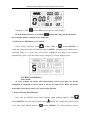
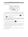
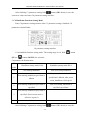
○ PAS Ratio (or Handlebar) Gear Switch
“-7.
Щ
Under normal operation, hold
button (UP) or
Ё button (DOWN) to
switch the power assist ratio (or handlebar) gear (ASSIST), changing motor output power.
Switching range is 1-5 gear (this can also be configured according to the customer
requirements), gear 1 is for the lowest power, and gear 5 is for the highest power.
1/
/
-ГГ А»
~_//э*Ё\_/$<
1*Il?<"IZI‘Tr/›rj:I‘><S / і тlilllziltllЦ
,
;
"r
E l ,1 [Til Tjljl I‘><l-ZIYJї"~"д`
Mn
|iI'*'~._I
III,II;::;_;IIII
"I l
Аззізт I(__
l
ASS l ST
Є; * 1
l l
|'l“ l I’
В
Ґ!l ўI‘
-
Il
Il
'
Ir‘Il7I‘-/l Ir Il
I‘
I Il
I__II
ll *ll l lЫ
_-!TI I_l l_ lЫ
_l_I_l
'
l
l
_/`
l
l I Il l l Il
3
_
Ell
,
,, _$__
r151
~
' l J1
l—
:3]
l‘“‘ITIl
l~;IT<»
T, "l i“IET,l ‘iTl !Ta;l l"T °_
.~'~'_~
._
I Il
I__ E‘:-K7‘
г«
_*
l l
‘\I,|
III
»I_
fiIl;li|F"l]=fl £119JNII
* Н,_Щд_д
ЁНЁН
”\
Ъ 1
Il l_
ll
l
Il I
lI'Ы
Il_l__Il llга пад.
lr
,,Ц —
1,,,
.Ti~
II
’ l ll
fl
IlIlIljlllIlIlll
I _ ‘I 1'
l ~l ll 1+
ll iélIII"1 l I‘ii?
I I I1 I/I
l l l
l l
l
г`^#
l_l
1* lҐ:l »l Il _;
А _
l l
Ir Ir
liil
F
Нщгпт
`їш'“
_ 1 _ 1 ші *
_
_ _4 _/\
_
Ilia‘,.i’I'Il;§;Il ,.‘iII,~TI I.\l I\l I lll il I
ll” .>=;IlЦ
l
Ц % ;› Ы У» « "И A її
її*
Ail/HI lwli
a
гд-Пї= 'дтдд \~'
,мм
raF~l_,lll;%».Ll
lll‘~.іlll‘__іllll_~Ш_
ll‘ ll“
I
-9-
\
.6‘
\I. If
W, lj ,=
.
I-I
і_/ _/<
//
\
РАЅ Ratio
Кайо (ог
Наш1ІеЬаг)
PAS
(or Handlebar)
Єеаг Swltch
Ѕ\УіІсІ1
Gear
At every startup, the meter will automatically restore gear (this can also be
configured as required by users) when it was at last shut down. When the power
assist ratio is gear 0 zero, there’s no power assist function.
○ Power Assistant Push Function
Users can use 6Km/H power assist function when pushing vehicles. Hold
button (DOWN), the meter assist function logo ( ) flashes, the vehicle drives at the speed
of no more than 6Km/h. Release
Ё button (DOWN), the assist function will be
- 11 -
ELECTRIC BICYCLE METER KT—LCD3 Product User Manual
revoked.
E: C
4QéI
WW Wym
TTWTTM
1‘I I__L<\I __II;I
1ї¦ ё››о< 882 :33 дм
WWU@IF
mPIFI E
Аээіэт IW
3%: ,ОО
//II/I
/_/I_
//M/M
/My
/II
/M
/M
/
III“
@_IM_ TIMIIIIIII\I I I
_
//4/\E/I_
\_\_
\
A
//R
gm
O0
\I_ffI_I_
pd//IIIIIyA/“IIII\M
7”‘
IIA\)I[I_I_|
/\\
IWAIIZ \3
III~‘\\I%¢<_\iIP/L
/,Ir_| _|\/II/>|_I/L|/I\“ ‘I (NI‘I /\&I I_Z
_\IFA
IK_II/_ V
II
. 3I
I _AII_H%
ynIO\_ fiJl|M
I\/I1“?
M
&I\UY£
SI
mwmw
F
W
m\/I\I_JI
|[i‘_% ®
п цц.иЁ;.Н,Ц:о:Кг:Ё
X
I
mV
I
©@
©
ёёївввв.зі±д+вв::
}I IXmII I \y
H _H_
/KQ
KmmHm
pcWIW an M
an
6Кш/Н рошег
аззізгапї
H
u
риЅ11 Ґипсгіоп
6P
S1 St
t
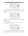
○ Cruise Function
When C7 parameter setting is 1 (see C parameter setting), the meter turns on cruise
‘I’
function, hold
button (DOWN) long to enter the cruise status when the vehicle
speed is more than 7 km/h, and the cruise function logo (CRUISE) lights. Brake or hold
any button to revoke cruise function.
:2: C
//4
//MI
WV UHIPIIWI I QUDIMI ii
>AII)I I v)
I \/I I/V_
&II%HIfi%
IJ‘v>
AITlIJ
QIIDI I TW
KII WXIHIFVI
AII)F
Чї 200383
=8Б
її..
C%£Wm
fig FHBI _IhIg
//’
I
0/
/I
,
///
//9
///
///
/
/
///
"z-vb“
*її
'ага
_I _w_R
I I _/\é
p
U
QM Q
FL
/(I I\ V\/T
M/ /I I \_\w
G
O
II§
p
/pII_II>//III)
_III_\/¢III\\p
I)AII /\I I
/IK
fig
KAIIIV
\I_II)“/III/¢
I IV IIKNI<_%III//\III€i
I Ip
VI/I
MMHIXU
\J\(\
VIII
_\/IV/IWk
H{N
Oi“
/D
Hwy *S_IIIx
~
AIQAJ
In) {L
MI\I fIIVAIIII@
дп Ьа.;Ёа ЁЁЁС
W%®
F
O
\ ёёїзввв.з:;+вв::
\\
_©_DMM @T_L
749$)
fip_U_
_/AHVAII I ®“UL /Iyh
II‘)
}
‘Kl\
H_W_
W“
W/Au
m
M
@@ F@
NIIA
IIV
CM/wk
O
_
C P _m F u n C fi__ n
SB
O
Сгиізе Рипсііоп
○ Startup Backlights and Headlights
E
Hold
button (UP) long, the meter turns on the backlights as well as the vehicle
Q
headlights (the Controller should have headlights driving and output functions), meter
backlighting and vehicle lights power logo (
ёэ) light, hold
to turn off backlights and vehicle headlights.
- 12 -
I
button (UP) long again
ELECTRIC BICYCLE METER KT—LCD3 Product User Manual
Ѕїагшр Backlights
Васісіідтз
Startup
аші
and Неа(11і3І1І$
Headlights
fr
'
$
~:
*\ =;\ ~д\ ^:зЁмЁ* (Ё Ё1 ты
=‘
‘i7l»’] U
T] “‘ U QМцНЩ*тт
TM
/ / / 1:
_:1І\Щ*(Ц
— `~' aH*r¢~*‘
UF? U!F/F1I F; TTM
—\ ¢
I
I
II
17
</\
1§
y.
>
(@151
@
,_
if,
_
/і\:{з:}]і}1
il=¥mQ»
H QT
W __
жд
/` \\_// `
/\_\\\i/f/»_
д
` \
-1_
I У/_\«/
I I,/
. *
«
Й
/Н М.:-<
‘I:I'
,_
\I<‘||—|'fiIL \/H,_
-w
/A‘
_!` \
~I\»»
/М
_ J1'_f»*
,-_ 1_
1_f1£‘
<‘i‘*~
дд
If \ Ii |
~»_ _/~ .\ \>,'~\|
I\_,_-_y ~T_7
МШШЕ ~“:×М Эд;
1
,_\ м,_
«,
\
/
‘
\*_
Y
U
ы
/\_\\‘\i/(/.\_
\\H\\]
\ 1
‘—\4—4
r"-K
\\‘
/?\~\\ ,
\
r,”\j//“I
\//
/І
A
/ ' «\
v \*7"
Ю1‘_
4
_/"—'<-__/ xi’
Q$1
A-J)-‘!~~\
2!її;“
\i,\
‘
'_
x
~
.
5%/,I »T§1]1:~ 1:Ч:×f3~§i/;±7~ mgm~@Tn1»R @*F W
_/ _
П _
мышц _`\ ,_ ,_ _/
@‘@@
\
"‘1 *
М.. “_
I“?W’) /U1 MEN
4IJffi]‘1 @F:
‘' “'
: : _
‘I W ‘W1W£14'J:*W§;uM
U1!
ЕЕ1 U*:Ё
Щ_ [KmЧ W1
/ їі
J1‘ “£1
A7,
МВТ
С ^:* :
w ‘+5/'
Q
\Г×_1М_
Pu 3 Hц>-15
(+4
4.
'g;@FiL_flé;E
““,r':‘I
( :_'*a
L
‘r,
I44 T\I I
'.¢_\
u
II
~- 1;
Q~
0
○ Battery Capacity Indicator
The meter can automatically identify 24V, 36V, 48V battery capacities when it is
supporting use with the specified controller. When the battery capacity is over 70%, the
four power displays of the meter are lit, when the battery capacities drop, the four power
displays are off in order, when the power capacity is less than 15%, the four power
displays are totally turned off.
When the controller is power off due to voltage shortage, the power display frame
flashes, indicating the vehicle has been in voltage shortage and waiting for shutdown
currently.
//
/ M
§~
S
“
L
m
I,; I—U @’¢p;A¢'
TM,
TTM
!~\
J
Ы ‘Id,
E’
/L?
Q
~
I §:5i;~».
HJ
1
,4" I‘
F
L‘
`
\
›
'
),
, V. /
F, __‘
I I
**
*
"
"SE
I
I '/‘III/‘1’II/‘1’I
И i‘
Ч :;:_”_`ї_
Н/ЁМ:/\Ё`
‘\1U *-M7 F6.13
_:-M)
I,
»_~._i,» _‘ »,~.'~*-1/_‘
\ \
^\ -j‘]\>~
,
И‘_‘I
MI
Ч \
*м
`М\ < >‘
‘
7 I I`
I“-;"IiI<~/'I
I
‘If
W7.
\_ _
I
м
7 /V, \
‘
7
I I I I
,:~.‘
11 щ
Ff?
‘H77.
JL uIf
=3
V
-*-
\
finfiq
I I I I
X
L[H]
J ~ ,5!
I I
‘
"3 Q,I
U}i§.flLQ\;Tq{i1)R
H
I I
I I
/.
,
N.
E
xHf)‘
‘ K/,
*:~ .
I)‘ __J K/_
I]
[H
H
Ix}
Bfmm
A
I I I I
\ j
’
,»/\
w}.
, \
F
1 w?*\
,
.41
,
xIIIL I U
I‘;I I2"/i‘:“,‘.~"I
‘I-if‘
/
1ил¦ фІл¦ ф«щ¦
’_/
’_/ /
/
/
/‘/
//
/
,/
,r1" \u-U
I I I IT
T .\ _.I
,
H/I‘
<~ \
if;~
LR}
~;“"’
\_\.
‘
7_
(Q: F MW
WU R91/‘F1
‘LU
"\*~_._.1"""
HIM H H
» ~~ , ті»
ff’/J
\)
‘L
3
“Й
i
г“\\<=`\`чш:* ИР \ 1
Ц
|V\_
.2 \~ V
7
Q
“.4
гїщ
,9)" M
I I AI I
I§§?.
« ~\ »
L‘
\\
"\
‘LE/|%/I
I I
*€/i’"
{L
*1
ЙМЮЙ
e /
I
I//"V
II:/‘
`
II I
/,1
`
_д_Г
,
И
_
If/J :,NH
I»
» I/I‘ffA (___> MP
W!
y
`
I.
`
щўг
\
I
I
\I
I
м I \‘x
H 7
, // "
‘.
’_/ /
'1
./
/ _/
/‘/
>//
_/
/
, // "
H
. /.1 '
4¦ »\¦
:І Ё
/,.’
'1 /
_//
/
/1/’
,1
/ _/
///
>//’
_/
/
/
, // "
‘.
'1 /
>41
1‘
, /.1 '
/, .
,1 /
4/
/ '
1
/ '
Voltage shortage flashes
Battery capacity indicator
○ Motor Operating Power and Temperature
Under the riding status of vehicle, the real time running and output power can be
known via the meter displays.
- 13 -
ELECTRIC BICYCLE METER KT—LCD3 Product User Manual
V114: ED 0 333 :33 3",,
ASSIST
H
—
f|Avs
‘mam
4.1 l‘n' _-.1
KmMP/H“ Q
MOTOR °Fw°c
I2|“"£S "Zulu:
'99
U 55cucu ‘.33 on Ion5'1!
CRUISE
Motor operating power
The operating temperature of the motor shows there should be a temperature
sensor installed in the Inner motor to output the temperature for signal detection
simultaneously.
V114: an 0 333 :33 I11,
ASSIST
r
U ‘
'1 I’! £1 ""£S
0 MP“ Q
'1 Avs
Z
I
‘flmfl
nininin
MOTOR °FW°C
UUOF
G@E sag
DJ''3'?UUU
A
! v.1.u I3":‘ 40.0.;
:0
-.:‘
Motor operating temperature
When the motor operating temperature exceeds the warning value, temperature
display flashes to alarm, meanwhile the motor controller will offer the appropriate
protection to motor.
○ Environment Temperature
After startup, the environment temperature for using meter will be displayed in
environment temperature display column.
V114: :0 0 333 :33 3",,
ASSIST
H
Q
flAVS
v2|""’£S
4.1 I‘u' _-.1
|.'§',','f/'1, R
‘DO
’ U ono
l
DST
CRUISE
VOL
‘mam
0:030
MOTOR °FW°C
2-:cuon .33on I v:-1|91!
Environment temperature display
The temperature display value may be in deviation shortly after boot-up, and the
display value will be gradually approaching the environment temperature within 10
- 14 -
ELECTRIC BICYCLE METER KT—LCD3 Product User Manual
minutes after boot-up.
○ Single Data Clearing
5 seconds after the meter is powered on, at display 1, hold both the
and the
button (UP)
button (DOWN) simultaneously for about 2 seconds, the single trip time
(TM) and single trip distance (DST) flicker, then hold
button shortly (SW), the
[
T
if
record contents of both will be cleared.
ct:cmc_:I :111::
*'
II'IiI‘@J
II.~.I.IrLJ~‘
..I
H
I
1*
I
I
\
I I
I
I
II
I
I
I
I
I
I
I
I
T
“*1 II
I
I
I
I
I
I
I
I
I
I
I
I
II ITIYTI
I
H
I I
Ix T. In/F;
I
_
V
I
I
I
I
I I7’, I I I7’, I
#I‘;‘I—5;I
II I I‘
U:/U:;I\_,_J
III Tjii"
I;~iI |I*:ii;><:‘ II;II7I:!kk‘II
II*iiiIiY<:‘ IIII:“VIfI%II
II“?}i,¥*<:‘
I I I I
I
I
I
5‘
*_I I I y4<I@
I I I j‘ III?
T V
I II“
A
‘VI
I
I
/If 7 ‘I
H
WFAII
I
I
#Z
IIWIIIIFI
"\
IL‘
'
u
->;I
I5:
_
Ii
I"
Ij::II'7§>.
“F IIIII JILL?
yV“‘
IQI F
Q@J‘iF1“r1’I'lr1IflMrfiw}+
IVITI
I
LIV?‘
I W
@FUUEE
//
Single data clearing display
Under the status of data flashing, if there were no operations on the data within 5
seconds, the meter will automatically return to display1 after 5 seconds, and the
original record content will be saved.
○ Automatically Prompt Interface
Error Code Display
When the electronic control system of the electric vehicle fails, and the meter will
automatically display (flicker) fault code. You can’t exit the fault code display only the
fault is removed.
//
\\
Ci;
I23
\\
Error Code Display
Error Code & Definition Table
- 15 -
ELECTRIC BICYCLE METER KT—LCD3 Product User Manual
Error Code
Definition
01
info
Throttle Abnormality
03
info
Motor Hall Signal Abnormality
04
info
Torque sensor Signal Abnormality
05
info
Axis speed sensor Abnormality(only applied to torque sensor )
06
info
Motor or controller has short circuit Abnormality
Motor operating temperature alarm
Under any interface, when the motor operating temperature exceeds the warning value,
the motor operating temperature display flashes to alarm, meanwhile, the controller will
offer the appropriate protection to motor.
User Setting Project
KT-LCD3 meter user setting project
℉ General project setting
℉ P parameter setting
℉ C parameter setting
General Project Setting
○ Maximum Trip Speed
Em
Under power off status, hold
5 seconds after boot-up, hold
button long (SW), the meter is turned on. Within
U
Y
button (UP) and
button (DOWN)
simultaneously for about 2 seconds, the first is to enter the maximum riding speed setting
interface, then the speed display column flashes. Hold
button shortly (UP) or
button (DOWN) in order to set the maximum riding speed value. The default maximum
riding speed value was 25Km/h. When the speed of the electric vehicle exceeds the set
value, the motor will be stopped driving.
- 16 -
ELECTRIC BICYCLE METER KT—LCD3 Product User Manual
\\
//
,\
I
UUH
RI
w
I
KL‘
~.
I
I
II1i:I;IIIIIII,I TTM
‘-3
II
Q MXS
I
I
~I—»=
~I
\
.1;
‘\\.\‘
/‘
.,
-_/
/\
Q
/
v
/I/II,»
I
I,I_IjI
QL
II*II@@ I @311
‘\
/
~/I
”f‘
(FA I51‘:
I
II
0 MM?/HH
,,y~I_
-I .
I I
::I\
,
,.
I I
,4 3:.
II I/I
/
Ii)
.
I ‘I I IT;IT@F% ‘QF III
If/>. /I
If/,,_
D
I/I
I_I§Jj‘IIy,I
IQIF
I
I
I S‘ I
II
*1~:>__
I I I I IiI»II WI I ITII ICIFQI
»I—\
UH
I;/I
1
I.~
~_»
.
I»r‘7_§
//
\\
Setting interface of maximum trip speed
Under the setting maximum riding speed interface, if there’s no button operation
on the meter for more than 1 minute, and then the meter will automatically return to
display 1, and the original set values will be saved.
After finishing the maximum riding speed setting, hold
button shortly (SW) to
save the current set values and enter into the next setting.
○ Wheel Diameter
After finishing the maximum riding speed setting, enter the wheel diameter setting
interface, and then the wheel diameter display column flashes. Hold
E
button (UP) or
'
‘in-I’
button (DOWN) to choose the corresponding wheel diameter specification to a
selected vehicle. The selection range of wheel diameter specifications are 13 species such
as 6,8,10,12,14,16,18,20,22,24,26,700 c and 28 inches.
\\
jg
U
L
I
ITTCITI I
II
I
II
~:
I
I
\\,\,/
/7€;lIiFI£I\\I
I
I
I ,;:*:i;\ I
‘5l_§f>“
I
I
I
>1
I
I/I
I;
II
I'TjI‘I[IjII'@I
"'
‘*’
I
I Ii’ I
ID
IIIIIJL
T
I
F)
1:-31'
I1:
/:*I:
2* »>¥f”I><;
HI/fliffll)
‘*I I
f
I
~'
3
/I
4 I
I
,~
4
Ii
<:j“*
III
I_
H~;'
O
,>;
I \\
I ~\
:, I III:
IIIIIQITIQIIR UF III TILE
/III‘
:<:**
~IIIIUIIIT
I Q
,:<<i;>;
I I II/I1 I I
; ‘L:IIIIIIIII
II§“fi-II,III‘I%II
II
\ZI IT*~-I)
II WI WI I ITII
II :I:I/I-§
I Ii I
II/I
“K
I
TM
I I~II»’—I:I~’I5:I
I?‘ *3I11’‘:9.:.':II'
=.
/4
\,
1
I
I
I
I
(I5)
K ,I
_
I
,/;<*;;
F
4
I
I
TM
<
\I
I
,
I
/°§1I
I
I
I/‘I.
I
I I
I\I
/'
II‘ ETII
I:I
F»:
III
I
I LIII/LIXI
“K.
>~
K
.
>~
.»
Ia
III; I I IQITIDI F-I ‘QF III
II”fl|f|iY|I“rIjI IEIII III II ,_IjI
I
I
\\
,
I
I/‘RI.
I
I
I I//I\I
L
‘
I
I
IIII III ~~\* AS IIIII IIII II II_I I
~—I~I
I_: . II—I~I
\ :_: 4
II “I:I"~I '*IiF‘~I
,,I
.;I
I
‘
IDIQQT
3:5‘
i»
1'
;»
I"
;>
".1
;@:
:?:
II;0_ll_twII II II
\\
<.
A
,1
TII I J
I;IIgI
7/
Setting Interface of Wheel Diameter
Under the wheel diameter setting interface, if there’s no button operation on the
meter for more than 1 minute, and then the meter will automatically return to display
1, and the original set values will be saved.
After finishing the wheel diameter setting, hold
[
1
if
current set specification and enter into the next setting.
- 17 -
button (SW) shortly to save the
ELECTRIC BICYCLE METER KT—LCD3 Product User Manual
○ Metric and Imperial Units
After finishing the wheel diameter setting, enter into the metric/imperial units setting
interface, and then the speed and mileage unit flash. Hold
button (UP) or
button (DOWN) shortly to make sync selection of three metric/imperial units as speed,
mileage, and the environment temperature.
\\
‘L
“iii H
~\W" .u\n,~~‘
W
._.
f" ‘ 4}‘
C
\‘
If
x‘
IJ
J‘
If
ér
1‘
3. '
‘u
\
\
‘J
,__
M
.~
V, ~
-‘
QJ1
i,~
\
,_
\
‘1§"'7‘i7
ii-I
\
.
\
\
‘
M2‘
\:\
~T~
'
rq
"
~ u
H>;¥fl*=A.<;i»\T\lwF%i F “W ~15
I
\ ._‘
\
M‘TW‘*“WZ*‘J‘
4' ~;'1;_:;
Km /|.| ,j
‘ZN" \ ZN
\ ‘
\W\\‘\W\\‘\W\\\’\
\
\,\
‘;V_\‘ ,\
‘ ;\V__\‘ ,\
Me'r‘§""fi"::—‘*
W
"
\
._
\ " \W
mi
““*;‘
\
J‘; J
J
‘ ~j*\
@[1?@i>
_J.‘ -3_2
Jj
w w M, ”
‘
"
[Iv T Q
U
U E
J J 7‘J J
‘ ‘ “ “ ’ “
‘
x)
J 1?
W
rf_‘7[j,\ O
» rs‘ 1’ J @,'»‘ » U‘ 1’ 7: M \‘ 1 1] M ll A J‘ 1’ ,4 J »‘ Q j w‘ F
\
\
? 1/ G’ )
'
\
"'1§
I H . \\
.\ ‘ \<
\‘I
~\
‘M\
1» , \ , I '
\
‘\
\ /“NJ;
- . F; \,
VI
\ ‘V
KIT]
*J‘J}‘
‘fi"V;VfiJb£V‘/‘ DC
//
Setting Interface of Metric/Imperial Units
Definition Table of Metric/Imperial Units
Display
Metric
Imperial
Riding speed
Km/H
MPH
Total distance
Km
Mil
Environment
temperature
Fahrenheit
temperature
Under the metric/imperial units setting interface, if there’s no button operation
on the meter for more than 1 minute, and then the meter will automatically return to
display 1, and the original set units will be saved.
After finishing the metric/imperial units setting, hold
[
I
if
button shortly (SW) to
save the current set values, and then speed and mileage units stop flashing. Hold
[
I
if
button (SW) shortly again, and the meter will enter into the maximum riding speed
interface again, or hold
[
I
if
button (SW) long for about 2 seconds to exit the general
project setting environment and return to display 1.
○ Exit General Project Setting
Among the three general project settings, after each setting is completed, if hold
- 18 -
[
T
if
ELECTRIC BICYCLE METER KT—LCD3 Product User Manual
button (SW) long for about 2 seconds, all can exit the setting environment and return to
display 1, meanwhile, the current set parameters are saved.
Under each setting interface, if there’s no button operation on the meter for more than
1 minute, and then the meter will automatically return to display 1, and the original set
parameters will be saved.
P Parameter Setting
After finishing metric/imperial unit settings, the speed and mileage units stop flashing.
5?;
'
Within one minute after stopping flashing, hold
button (UP) and
‘in-I’
button
(DOWN) simultaneously for about 2 seconds to enter P parameter setting environment.
○ P1 Motor Characteristic Parameter Setting Mode
P1 is motor characteristic parameter setting mode. P1 = motor gear reduction ratio×
number of rotor magnet pieces, just rounding if there’s any decimal.
After entering P parameter setting environment, the first is to set P1parameter, P1
parameter column flashes. P1 setting ranges between1-255, hold
/
button (UP) or
button (DOWN) shortly for selection.
//
: T
1T
\
QEU
L
mi’!
\‘£‘,»zi;v(:
:
i
*7‘
i
T
}
,
' \
\
\
x‘
\
‘
\
\
»\
?
\
K
r' §
4
*2 » ”
Q
,;_
‘re
r*___i\
_
i
é
T
T
T
T
_
\
\ J; \
J J
- Ll
r—\
' ;/‘
‘\
‘
n NI
jt
?
EU U
[SW
I»M,7?
U‘ j
\‘_J
:1»
i
VIII’!
3
Zggui
FIE I
___E,/
if
P1 parameter setting interface
Under P1 parameter setting interface, if there’s no button operation on the
meter for more than 1 minute, and then the meter will automatically return to display
1, and the original set parameter will be saved.
After finishing P1 parameter setting, hold
values and enter P2 parameter setting interface.
○ P2 Wheel Speed Pulse Signal Setting Mode
- 19 -
button shortly to save the current set
ELECTRIC BICYCLE METER KT—LCD3 Product User Manual
Enter P2 parameter setting interface after P1 parameter setting is finished, and P2
parameter column flashes.
TM
fl@
J7: /.1»\[email protected]
"5-P
-FT
1,=\@;~q;» @.;~:~
\
r\
.1 i ,7
\
I’
JI
,
\‘
1%’
j’
‘
?
'f;;._
r” 1* "
i i’
‘
._
/ ’
V \‘
/
/
I
,
3
‘?
A
‘ff
_
':/
.r~z;Z?»1: ;;._,:;
W/4 1' e‘ H if I “
\
%
LU
/ /‘ ‘
§‘vi;j"{
\./
,_.
‘$1
,_\
Ml1T@iI?*F%l
H
£§l,‘@}{Ql7
ELMST
\\ .7
V» »
-V 'f:§:i{T
If 7
“x
\
\ \.\\i1/, . F3
JIFAZQ;
I/l_L I M1?”
\
’
,
\ 1 L.
MM
J
<~"'
;_
,
//_—_'
1
FW
I Q” Eii rrn ”*r%;' ,'iU; »"]U[ /
F
P2 parameter setting interface
P2 is wheel speed pulse signal setting mode. If wheel generated 1 pulse signal by a
revolution, P2 should be set as1. If wheel generated 6 pulse signals by a revolution, P2
should be set as 6. If users didn’t configure the pulse signal system, and then P2 parameter
_\
F
‘,7.
setting can be 0. The setting range of P2 should be between 0-6, hold
shortly or
4
button (UP)
button (DOWN) for selection.
Under P2 parameter setting interface, if there’s no button operation on the meter
for more than 1 minute, and then the meter will automatically return to display 1,
and the original set parameter will be saved.
After finishing P2 parameter setting, hold
I
I
if
button (SW) shortly to save the
current set values and enter P3 parameter setting interface.
Please Note when P2 parameter is set to be 0, for the built-in clutch motor, there will
be the following defects, when the internal motor rotors stop or the internal rotor speed is
lower than the outer rotor speed, then the speed displayed on the meter is inaccurate!
○ P3 Power Assist Control Mode
Enter P3 parameter setting interface after P2 parameter setting is finished, and P3
parameter column flashes.
- 20 -
ELECTRIC BICYCLE METER KT—LCD3 Product User Manual
U
5:
HM/ _W‘‘2
_w_‘_Z__
§ L?{
_ __Kll q
V
h_,__
_‘ILV,
M,
“mifirn
Q
I
C
F: E
‘M‘AI
W“?
:
2
NHLHM _@_3
A‘)
fl”/pfQV?__
,
_
L
‘Q
3'.
\‘| H
i
L”
3;/FHII‘,\iH
i
7}!
P3 parameter setting interface
P3 is for power assist control mode, when P3 parameter setting is1, power assist
control mode is gear 5 of "imitation torque control" mode, when P3 parameter setting is
0, power assist control mode is gear 5 of "speed control" mode. P3 parameter needs to be
Q
E
determined according to the distributed function of the controller, its setting range is 0 or 1,
button (UP) shortly or
hold
button (DOWN) for selection. P3 parameter
setting method is the same to that of P2.
○ P4 Handlebar Startup Mode
Enter P4 parameter setting interface after P3 parameter setting is finished, P4
parameter column flashes.
i
\/
E
S
S Rik/W
_\\‘,/
QXJIHMU
V/Lyr’EV7
HI,7
_{Jff\I \_‘’\ _r'§‘Jy
ill
¥ Al}(I
F}
__‘//,r|'_\,;\_,¥‘
V‘
_
HQ“A:‘“_ UK’F5Q
1ilk?
__\/‘H\
\:L FWM
@
T
L
I.ll
f
“_
llX\‘_/V)‘M\/
_‘____,, _“ny1/
{A1
KV(J_H§{‘
/
5KKK71‘W}
_
S
k_
‘lllwt
___‘|‘|_
P4 parameter setting interface
P4 is handlebar startup mode. When P4 setting is 1, indicating the handlebar is under
"non-zero startup" mode, namely, the handlebar can be effective only after startup the
foot power assist. When P4 setting is 0, indicating the handlebar is under "zero startup"
Q
E
mode, the motor can be startup by the handlebar directly. P4 setting range is 0 or 1, hold
button (UP) or
button (DOWN) shortly for selection. P4 parameter setting
method is the same to that of P2.
○ P5 Power Monitoring Mode
- 21 -
ELECTRIC BICYCLE METER KT—LCD3 Product User Manual
Enter P5 parameter setting interface after P4 parameter setting is finished, P5
parameter column flashes.
T *=a¢wQtT%W@WM
@@%HwT JW,TJ
_
1‘\”\“» " J \‘ TL '1
J
‘r
\
J
J
I
_<
, * é,,
\‘
\‘
Q
x‘
‘\
1
_ 1%
\
I
“\
\
\
J
\
I‘,
C
K
V, Y‘
“ ‘
I
Q‘-:,*“TQ: J
\*1 I '* HW?1*’H
‘\‘\‘
if
[P
U
u E
_
/‘C1
Y‘
I
B~<i_m,.-/‘H
j
\i§L1.1 [11@13 »
/a*"\ /af \
\‘ "\{ J /_a‘ . J J‘j_,U
U_M
_
‘ ‘Hr ‘ ?;.fv_I€~
‘ L‘
.7_
\ l%_"i;‘Y'
Féfl fl x w !,L»‘1 x @ q \
V’
‘ D
f
‘
1‘ M 1]
‘Z!L_;<_Iii
|:|
F THY ‘1C\1,;::U
+1»,
_!'|
WK fy
V/\ \‘
fi
'\
i
H<L&flA<.L;\i\T\i@1~F;
|i|
' 1»
I
r
Y"
"1
Q |:\\ |:_\
\
\k:I..
mil ‘
7
Q.‘
\
\ *1\
ik\ y[ L\ 721+}:\ _1 \ \ \ *1;
—
\
M
1'
\
1:.
‘.»
\ ‘\
_\
~
\
:
_
M
, I?*T\\_A
L\._ n
P5 parameter setting interface
P5 is power monitoring mode, when P5 setting is 0, the power monitoring is the
"real-time voltage" mode. Namely, it is the method to determine the battery capacity
based on real-time battery voltage. When P5 equals to a specified parameter, the power
monitoring is the "smart power" mode (this parameter is determined by the battery
characteristics, ordinary 24V lithium is generally is 4-11, 36V lithium is between 5_15). P5
setting ranges from 0-40, hold
button (UP) or
button (DOWN) shortly for
selection. P 5 parameter setting method is the same to that of P2.
After finishing P5 parameter setting, hold
I
I
if
button (SW) shortly to save current
‘L
set the values, and then P5 parameter column stops flashing. Hold
button (SW)
shortly again, the meter re-enter P1 parameter setting interface. Or hold
button (SW)
long for about 2 seconds to exit P parameter setting environment and return to the display
1.
○ Exit P Parameter Setting
Among the five P parameter settings, when each parameter setting is completed, if
held
if
button (SW) long for about 2 seconds, all can exit the setting environment and
return to display 1, meanwhile, the current set parameters would be saved.
Under each parameter setting interface, if there’s no button operation on the meter for
more than 1 minute, and then the meter will automatically return to display 1, and the
original set parameters will be saved.
- 22 -
ELECTRIC BICYCLE METER KT—LCD3 Product User Manual
C Parameter Setting
After finishing P5 parameter setting, P5 parameter column stops flashing. Within 1
minute after stopping flashing, hold
button (UP) and
button (DOWN) for
about 2 seconds to enter C parameter setting environment.
○ C1 Power Assist Sensor and Parameter Select Mode
Set C1 parameter first after entering C parameter setting environment, C1 parameter
column flashes.
\\
f
‘ “*‘
J JPi J [JJ
J
J
/fJJJ
J
“JJ~-J_“J
J J J \~_
H
I/JV J
J
J
‘J
J
J"
J J
‘J
‘J
J
(‘J _J
‘J
J
J
J
J
J
J
‘J
V
J 1
J
-_-;;§Ji-:¢_
J
J
J
J J
J
J
J ‘,J
‘JJ ‘J;
Jqc,
:_‘J
‘
‘,»»,.‘
J__
‘J' "J
“IV
I ‘J
J
J
Li/JJ‘J‘>“EJ“JJ-.JJ
1
1 ‘V/J H
‘J
J
‘J ‘J
J
Tfi~1J_JJ
J“J—JJ"J J“J—J~"J J“J—J"‘J
HJ‘dJU;'7k‘~l; T;_;§J
J
‘J,
‘,J‘J ‘J ‘J
JJ-_ J‘,__iJ_J‘_,,J J_J_J__J J_J_,__JJ
JJJ 7§~J,7 ‘ii?
“J
J
‘J I
‘J
J‘;
J
JJJJJJJZJJTJJJQIJFJJ
J.
>1»,
‘J
‘
‘J
J
-.~\‘___‘J
JJJJJ
JIQJ ‘ J ‘JJ7?J4
J
J1
‘J
J J
JJ@1J[1iJJJJIJ:J
U "_;,ZJ E
*
i J
JJJJJJJJ*J‘;J
J
MJEJ _J J J_ ,,_, J _ 7
‘
-.
,
J
//
C1 parameter setting interface
C1 is power assist sensor and parameter select mode. Its definition is shown in
following table. C1 setting ranges between 0-7, hold
button (UP) or
button
(DOWN) for selection.
C1 parameter definition table
C1
Quantum power assist sensors or similar
C1
Power assist sensors from other
value
products
value
manufacturers
00
5 magnet sensor
05
01
8magnet sensor
06
02
10 magnet sensor
07
03
12 magnet sensor
04
After finishing C1 parameter setting, hold
[
1
if
button (SW) shortly to save the
current set values and enter C2 parameter setting interface.
○ C2 Motor Phase Classification Coding Mode
- 23 -
ELECTRIC BICYCLE METER KT—LCD3 Product User Manual
Enter C2 parameter setting interface after C1 parameter setting is finished, C2
parameter column flashes.
//
fix
Vii
(T
/:\
‘,~J\‘;‘_“‘/.‘
<
UT J@wm@
, J‘ ‘J ‘_‘,J‘ “:‘.,JJ\‘ “J“:,_‘J
~M@MJ
J!’
“VJ
Z
~J
J TJJJ
,f
/%\
JJ.
\
5‘
/,
‘\—J’
\
Q
O
*M_J;'\.;\_4r’
X
J
JLJLJ ‘J T T M
J\
L <~_ J;
JJTJJ" “Q
\:}'J
'1"
J J_ J J J J
TJJJTi:?J<1>§;;»
~>‘j~-‘ J~~-‘—‘»~‘
W%TTTCFWw@mWm@
J My T
J
-
T
J
J
J
J
J J)J J
J
J J
J
‘J
‘- 'J?JJJ~‘\
J
j
7/TJI:-/'1
J<.w Q
J J ‘ T J H —’
W
‘J/ J
J
J ,f7J
VI
L
*1:
J‘
.1’
/f
-.,;J
“ ;J“‘:‘
‘Til
‘
\
F‘
“
J’ F
.
T1‘-Jr
JJWF
,\
FT‘
J
J
E ,
~%@WJ
Wflwmwwww
m-»
TM”
43
@fl@mW@@@
JJJJ
U
JJJJJ F V1
F
E
\\
C2 parameter setting interface
C2 is motor phase classification coding mode. It is served as identification parameter
of different phases of the motor when using sine wave drive and the default value is 0.
When C2 setting is 0, indicating that the used Quantum motor phase is an ordinary one.
When the setting is a certain value, indicating a particular motor phase is used. C2 setting
E
E
‘ti;
range is 0-7, hold
TI
'
button (UP) or
‘L-1'
button (DOWN) for selection.
After finishing C2 parameter setting, hold
I
I
if
button (SW) shortly to save the
current set values and enter C3 parameter setting interface.
○ C3 Power Assist Ratio Gear Initialization Mode
Enter C3 parameter setting interface after C2 parameter setting is finished, C3
parameter column flashes.
//
Wfifigmwwfifififlz J
TM
wk
‘H
‘J-Q JF.>J§a
JJ£J~‘J~iis@J J
fig
‘J
J JJ JI JJ J J
I
Z
J
/_i__*1
~3~~iJ»’
;_fi
/i——-
I,» -.\‘
‘\‘=‘
<\J._J \
/
J
‘ivy/t
/
J
J
JJ\
\__/*'
J‘
/g
J T TM
%%Jwmm
g
K»/7 (‘Jim
[fw
/ii
JL
/‘i
/A
EJJJTFH
‘JJ
U
/
J
(]JJ’J\J_~;
JJ JJ J1
J
__/‘
‘-
&
JJ
F‘
/C)“
JJTJQJTJQJR J“ F JJJJJ JCJJLJE
mfifiWJ@MT
JJJJJTJL
U3 Q E
.J
._
\\
C3 parameter setting interface
C3 is initialization mode of power assist ratio gear. The setting range is 0-6 (gear),
hold
T\
J!
button (UP) or
4
button (DOWN) for selection. When C3 setting is 0, the
meter is switched on, and the power assist ratio is at gear 0. When the setting is 1, the
meter is powered on and the power assist ratio is at gear 1, and so on.
- 24 -
ELECTRIC BICYCLE METER KT—LCD3 Product User Manual
After finishing C3 parameter setting, hold
button (SW) shortly to save the
[
T
if
current set values and enter C4 parameter setting interface.
○ C4 Handlebar Function Setting Mode
Enter C4 parameter setting interface after C3 parameter setting is finished, C4
parameter column flashes.
§?““1\H111MUMJ_~1 ,1.
:1;/1 ~::1_1:_;J~
__
1 ST
* /1'
1
1
1
I
11
1
11
1
1
K
1 --,:“{k
1
1
1
,1/1%
1 *1’1 1 1
11
1111 111.
1__
£171
‘~
P
1
‘J’;_:;‘r€{:L___(
1 1
1 1
‘J
=g_;_
ii
1 1
1 1 1 1
C
1
‘1 Pi’?
V
I‘ J1
11 4 -'1
1 .‘7[,»1
1_1_1
‘
‘
1 1
1
1
11v?»/‘ML\1;é/1 1:1
A/1 A/1
TTM
J1T\ L T. ‘nfi1111:;
111 1111‘
11:1
11-1 1<_11
‘F
U11;11UL1:.:;r*;‘-‘
1 11
;;1
‘
1
1
‘ ‘ +1
7+
11
"T11
1 1 171 ~11 1
)1
.1
11 1 1711’ 1
1 1.1 11 ‘11F1711i:.‘1
11 11
if
1
1
1111 111111TL1j
_ 1T1l11111F’l 1Q’F1:1'1111;1;,
E1111?
1 7 1””
1
1
,—~,~ ~f:T
1\ /'
11
[11 I)‘~T V11
1 1 1 ‘,1
\
’
1
1
1
1111“ 11»
» -1 1 *
1
—
1
_
———
‘ U
11i}1F”%j L1. U QE
1L’ 1
1711" ‘
1
1
-
1
Hm
H
M71‘
Jill‘
fI
‘ J‘, *7? @
fijfif \ j,}_(( \ ha) C7
“ J+1:k‘
‘V W!-!1“11W
h:,1_1.__‘
‘L
W1‘1W 11%
0
C4 parameter setting interface
C4 is handlebar function setting mode. The setting range is 0-4, hold
._,./
Q
button
'1‘
(UP) or
button (DOWN) for selection.
C4 parameter definition table
C4
Handlebar startup mode P4=0
Handlebar startup mode P4=1
value
0
zero startup handlebar
Non-zero startup handlebar
Before power assist, the handlebar
Zero startup, handlebar speed limit is
1
speed limit is 6Km/h, after power
6Km/h
assist, handlebar is full speed.
Zero startup, handlebar speed limit is
Non-zero startup, handlebar is
specified
specified speed limit.
2
Zero startup, handlebar speed limit is
3
specified. (Power assist ratio is
effective at gear 0)
4
After finishing C4 parameter setting, hold
- 25 -
[
I
if
button (SW) shortly to save the
ELECTRIC BICYCLE METER KT—LCD3 Product User Manual
current set values and enter C5 parameter setting interface.
○ C5 Controller Maximum Current Adjustment Mode
Enter C5 parameter setting interface after C4 parameter setting is finished, C5
parameter column flashes.
1§1:1f11 11115111111
T1111
TT111fl
1
1111 1. __ . C‘
1:1
\11-1
L1‘ ‘-i~"»;111”3;1‘
H
~;__.‘1'1T_I
11 1-1;»!
1
1
.
1
111
T311
1
1111
1.1.»
11
11
‘~.> ~'
11111—1‘1‘11 11‘ 1
1
;1 i,
1"
1
‘~ 11:?
1
1 11
1
11111
§;:11j1,_:ii
A
I
1
1 11
Ii;
1 1
1*‘ 1 1 1 1 1
1
1
1
1
1
11-1\. 4/1_\1'1
‘A‘;':’1
111111111“
,__
1
1111111—11111—11111
.11
1
1
1
1,1
"1, _.1
"1, 1;
1
1
_1
,
111111/H 1
1111
E11
1 1 1 t1;1 T1:1;1:1 1 1 11F
Q11 111.1
1*
d
1
'1
"1"1
111L111'=»
111111 1
1 1
1 1
1
1
‘"1
LU
U E 1111111111! 11 110 L0
11
1 F
1 11 1 1 1 1 1 1 1
1 >1 1171:1711‘/<11 1‘_:71iV
*
1='Lii=~*
‘ :::~1
C5 parameter setting interface
C5 is controller maximum operating current adjustment mode (tiny-adjustment of
limit current value). The default value is 10, setting range is 0-10, hold
or
~1
1
button (UP)
button (DOWN) shortly for selection.
C5 parameter definition table
C5 value
Maximum current value(A)
00
Maximum current value-5
01
Maximum current value-4.5
02
Maximum current value-4
03
Maximum current value-3.5
04
Maximum current value-3
05
Maximum current value-2.5
06
Maximum current value-2
07
Maximum current value-1.5
08
Maximum current value-1
09
Maximum current value-0.5
10
Maximum current value
When C5 setting is 10, maximum current value is controller maximum operating
current value (ie, limit current value); when setting is 9, maximum current value minus
- 26 -
ELECTRIC BICYCLE METER KT—LCD3 Product User Manual
0.5A, when setting is 8, maximum current value minus 1A and so on.
After finishing C5 parameter setting, hold
button (SW) shortly to save the
[
T
if
current set values and enter C6 parameter setting interface.
○ C6 Backlight Brightness Adjustment Mode
Enter C6 parameter setting interface after C5 parameter setting is finished, C6
parameter column flashes.
1 11;;
1
1
i11fi711‘~
Z111)/’
“#1
1111“1Y11'111111 1
g
1
1
1 11
1/
1
1
U
1 QE
1 1
11:.
111g'T11':::'11
1 11111
1 111*11 1111 1
1
1
‘1
11
1
11,,1_1,11
1 1 1 1 1
11 71
1 1
1 11111
1
11141151211111
1
"
11 11111 1
1'1 1 1
1 11
11111 111,11: 1t11;1:1;;<1 ).:1:j1.;f Q 1i111;;1:11:1
‘=li:_/11 -
1
117 T1 17111:”
1
1 1,
_1
1 1
_1 1
11M
H111M1111
11 .1~11 1 __;11 1
1
1
11
115
1
'
1111-11"”
1:1
11 1111 1 '
4 1. 1
1
1._1
J;
11
11
11 1 1 1 *1’1 "1 1111111111 1
,
1,_.r
1
1.
,
1_
1W1 71 “ 1F 1W? 1
"1111/11;!R1Q~1iF%1
1 112111111 :11
1
1 1
1
1;
1
11;;
~/'
@1111i11'H
1 11i1"»;1<1 11;‘
1 1
L 1,1
111111
@@@1iIF‘IF‘€? II 1ij*11
1Ȣ_@@_@@
fl%m:agJ!-,@§;1..;
11 1 11 '
:11‘
1111111195111111111111111111
11111 1111111
//
C6 parameter setting interface
C6 is the meter backlight brightness adjustment mode. The default value is 3, and
setting range is 1-5, hold
button (UP) or
button (DOWN) shortly for
selection.
C6 parameter definition table
C6 value
Backlight brightness
1
Dimmest
2
Darker
3
Standard
4
Brighter
5
Brightest
After finishing C6 parameter setting, hold
[
I
if
button (SW) shortly to save the
current set values and enter C7 parameter setting interface.
○ C7 Cruise Function Setting Mode
Enter C7 parameter setting interface after C6 parameter setting is finished, C7
parameter column flashes.
- 27 -
ELECTRIC BICYCLE METER KT—LCD3 Product User Manual
//
\\
_
if
RTR R"RL:§1f11:R1
(FL
R
,1’
R)
j
,R'\
‘
. , K,
R
RR’
RR R
R
F
E?
RZRRY/»'
‘
R"
/"
R
'
»;TR;<R
K
R‘ R R‘ R
’ ’
./ R
1:g,.R‘
R
‘
‘
J1’
‘
J
R
l
}
RR R R
I
R
R
R‘ R RVR‘_R’\ R R¢:R‘_J\dR
C
R’,/'
T
RR R R “Réy R R RR
LR R.,LR,
Q givi
' RR/1
I RRRFH
5R
R,
R4‘
“R TM
CR Ri ‘R‘RiRfRiR5/RR‘
R TM/,:L.
R,R_R\_R
E§R~1R
Rf R3,
RR
\__.:_j
l
}
RLR,R‘_R\yR
fF
R _ RR
MR T
La
HR
‘R
,s__ilTfrR. Rx
R'r—\‘_ Ry '[‘__:‘_RR
RRZ,
R‘ K
\\;L"i
R,
RRL/R'*R‘iVRR
:
‘
R
K ‘/' ” X
,RR/ii‘:-.
R‘\»§‘.*;::_I':R”
:
RRRR “ ”RRR:;
R_
A
,
RR‘-?.%ZfRR RERF
‘LR’ R Rm RR RR RR R
R
U
Rn L;
J
\_
0
\\
C7 parameter setting interface
C7 is cruise function setting mode. The setting range is 0 or 1, hold
or
button (UP)
button (DOWN) shortly for selection.
C7 parameter definition table
C7 value
Cruise function
0
Off
1
On
After finishing C7 parameter setting, hold
[
T
if
button (SW) shortly to save the
current set values and enter C8 parameter setting interface.
○ C8 Motor Operating Temperature Display Mode
Enter C8 parameter setting interface after C7 parameter setting is finished, C8
parameter column flashes.
//
<7;
\iF‘\.
»:iT:\
‘ii L//_,
R \3;;t;;',,RR \
El
H
R"
R",
~‘R
R
R R
\
/
‘ R
/R‘
I
R
}
-R
R
R
R
;1R“‘;:V~‘R
, RI
RI
RR’;
,
’iR
I
R/'~kvv~“?R~tR/:5/‘RR
R R
‘R
R,2 ,;R—~;}
‘Jr
R R
\,;;! Hit
R RRRWR RMTRRR TM
‘
C1
I
R“
“.
R‘
/y,.__R‘RRRy A1‘
‘/
R RRR
R R R R R
(‘R_/ii:
,» / \
R R R R
R
R’.
R
’
\
R
7 R‘
,6
RRJ
‘Rf RRMRR
T
R R
R
F‘\"/1|)’;
"Vi
R'c'V“R';1‘R
' ‘R
IDR
R _J
R1?“ V
R'/Q*R"'“‘
R"\1
R,WT \
RR,R. Tm \.
W
,_,_ R
H
'f;>H
\‘~__RJ
RN! {Er
T
R‘
EQ
Lg] F
RRRiR:R'LR RRR RR _,4QRR RRé;R:R;iR
,
._‘T
R‘
.‘J
Ra’
.
R1,'»,
Li;
‘R F
1'
RR
R
//
\\
C8 parameter setting interface
C8 is motor operating temperature display mode. The setting range is 0 or 1, hold
'
button (UP) or
button (DOWN) shortly for selection.
C8 parameter definition table
C8 value
Motor operating temperature
- 28 -
ELECTRIC BICYCLE METER KT—LCD3 Product User Manual
0
Function off
1
Function on
Please Note The motor operating temperature display requires installing temperature
sensor in the motor, output temperature detection signal simultaneously.
After finishing C8 parameter setting, hold
[
T
if
button (SW) shortly to save the
current set values and enter C9 parameter setting interface.
○ C9 Startup Password Setting Mode
Enter C9 parameter setting interface after C8 parameter setting is finished, C9
parameter column flashes.
//
RR
L
ii R)/,
RR
R
R
*Rir~:rR R:?~??R1wm
R CR RR R_R RR RR_RR R, RR_R RR RR_
W€;¥K%R%;RF'i”WRw TTRR
, RR
RR
R
R
A
=1R4R*R‘
R
R
R
R RRRLRR R,
R
R
:7
1 *
R
RR
U A
.__R
R
R
R
RR
R
R
RR
R
R , RRRLR
R
‘ ‘
R __ R,‘ ‘L,
RR
R
RR
R
,7,/R7R‘:;:
1;
R
;2=‘
R"R “R FRFQ
R Rf“ R
,
R
RRRMEH
RRRQRUTRRRRRRRR H RRR
RR
‘V 'R
I,
/.
.~R R R R<R R RR*~R*~R R RR R*R~R
R R R_R_R R R_R_R R_R_RR_R
RRR
R R
R
R
RR,’/Rf‘!-.__RR Rf_LR__RR‘
M@T@F‘%§WR@
R L
RR, ._TRjRV,;;RRR RTE
iIWQ:@fi:WIfH H:HRRM _RRR R_R.QR‘F
[R[R§§RT
R RR_R.R‘L’*RR R
R1‘ R
R‘ RR],-
R T1
R R*R R RHRRKRRR B"5§TUU‘
R‘ U ‘7RR RRKR RR»R RR RR_._J
R
//
C9 parameter setting interface
C9 is meter power-on password setting mode. The default value is 0, hold
button (UP) or
button (DOWN) shortly for selection.
C9 parameter definition table
C9 value
Startup password setting
0
Function off
1
Function on
When C9 setting is 1, hold
U button (SW) shortly, indicating that the password
[
I
if
function is startup, and then enter the password settings interface, three password setting
columns flash.
- 29 -
ELECTRIC BICYCLE METER KT—LCD3 Product User Manual
5/
x-\
RR
;¢RR~@R :1~"@*R@m;mu1RwRmm1RRRM
.RR — RR“
.J\:>R R,RrR\L~,1}
~
k,‘ERR
P».;_
R IRR4 4;?/R R
R
R”
R
R,"
R»‘RRa|RjR"
R‘KR
R
RR».
R
R\_~. ,
~~ ,
Rf,’ R
1
R"-R RR“
R
lR‘:\‘s ‘RLR’ 1;?
R
..47¥R~'
R _,,:
R ‘AR R
R R
RR IJ Li L‘
R/ ' R
_;
R R R A RRRPRRRGQRR
R
195255235!‘
R (Y-Y-R7R<):\;I
R R
I RRR.
V
R.\
.41
RR
‘R
PR
\
RRTREIRTRRIR
A
F RRRRR
R
RRR
2*
"PR ‘RR“":R'
R+?R71>R
§'R’”
HST l'R1:R,R I:
n R 9;-
RR_!R7l R _‘;R§R Q_R RR RR
RRRR§i,,,
R R 0. RR—RRR RRR
-,R
k»/
3
_
R1
57‘
RiR RR
RR:RRR,R ‘F
ex R
//
\\
Password Setting Interface
ll
The password setting is done sequentially from left to right, hold
button shortly
to confirm after each setting and enter next setting. Password setting range is 000-999, hold
>
E
1?
button (UP) or
‘in-I
button (DOWN) shortly for selection.
Please note If you forget your password, the parameters can only be copied (see
parameter copy) by data source meter prier to be decoded.
After finishing C9 parameter setting, hold
[
T
if
button (SW) shortly to save the
current set values and enter C10 parameter setting interface.
○ C10 Automatically Restore Default Setting Mode
Enter C10 parameter setting interface after C9 parameter setting is finished, C10
parameter column flashes.
//
\\
,.R>~
R
’€F*i?%—*H
¥#R%%
RRRRRRfiRRRRRRRR_RRRRR R
RR
,Rfi_R R T RR-RR
ERR“-RRR
T RRRR
ASSRST §==a
j
R
R R
R
R R R
R RRR4R R
R
RR
K
R
R R
R
"R
Rx
RRR
~*@R%w@1
R
,;/R
R
RR
R R_
R
R
R
'i‘:\R- "
R RR
R
R"‘:"IR‘_R}‘;R'
R RRYR
ix
:,>‘\
/--:\_
RR » .
“
“RR
RR
RR
_
ME7 E'“"‘ RRR
Rh;
;§%
,__
R
:0 WR
T
R
RRR
R RRWR7 Ii?
__
RWRRHRflREH
‘t1:R5'**¢:: R tr’R_R
RR'i""R Rm R Rf,
T'?'€
r: _
RJRRJR;
L
QR
M@TwR RFR RLR
“éLE5-,3
“RURMRfRW@R1fl@F
QT
,3BRR;R‘R‘R
R R Rf,RLRRRA\R Rf‘, R_RR3RR R5
//
\\\
C10 parameter setting interface
C10 is automatic restore default settings mode. The default is n, and the setting can be
'
n, or y, hold
button (UP) or
4
button (DOWN) shortly for selection.
C10 parameter definition table
C10 value
Restore default setting
n
Function off
y
Function on
- 30 -
ELECTRIC BICYCLE METER KT—LCD3 Product User Manual
When the meter is needed to restore default setting, C10 selects y, hold
[
T
if
button
long for about 2 seconds, all parameters restore default settings and exit setting
environment, and then return to the display1.
C10 selects n, hold
button (SW) shortly to save the current set values and enter
[
T
if
C11 parameter setting interface.
○ C11 Attribute Selection Mode
Enter C11 parameter setting interface after C10 parameter setting is finished, C11
parameter column flashes.
//
SH
L
M (‘Q3 U-*1?‘
s'¢:\“~".fLi'! ~"._fJ~1'
“
RE F
U-31‘
, ~‘
(V
\ ,
K
E!
‘
V)‘
in \),,
\
\‘
\¢F
F
‘K
\|‘ ill‘
_
r’ ‘ 1%
‘
ii
' ,_.;i:/~_~ -
“
q’ J
»
/’
A
r J A J‘* . \ \
AW‘ H 1‘ M
.?\
‘jI»;;:[:§,l:_ ,",,i{_‘y:?‘.%,';
a_\
F
T
ci\ “ '7*»§'~‘7 »\\~
,
J W‘ V *““ “*
‘N
_
r'\“i‘\‘\i"\
I s J J 1 J J J J 1 I 1 .~ \
»’
M11 l]I5Ij¢ um ~L%A»:é;,i
\
‘A
[,=‘”/
"
‘l.;‘_;:'.‘i+-.“ ,f1.;lv_:']‘;;‘ _‘;3":_‘i',§f
‘kLiJl[:k:kyJ\ Lv}‘_“;‘\
J <7.
Hm
[0
\/":'\
,:::\
1
‘F W
xi
F
,1?-\
-...‘
‘
1\
/
I1]
[MT ‘L H
U
R /?ijr:I ./A
7
J ," 1‘ ff
M
Dim]
V,
P7
I \ w-T
Jjiw 55‘
rm /1:i%»‘ ‘F
\‘
41/ LLJ»K‘
L,_
::§,>|,“?rD
‘Q
C11 parameter setting interface
C11 is meter attribute selection mode. The setting range is 0-2, hold
(UP) or
button
button (DOWN) shortly for selection.
C11 parameter definition table
C11
Meter Attribute
value
Meter uses LCD3 new version of communication protocol, it is compatible
0
LCD1 and LCD2.
Meter uses LCD1 and LCD2 old version communication protocol, it is not
1
compatible LCD3.
As data source for copying parameters, the meter transfers the new LD3
2
parameter to other meters.
C11 selects 2, hold
[
I
if
(SW) long for about 2 seconds to exit the setting
environment, and then the meter is served as data source for copying parameter (see
- 31 -
ELECTRIC BICYCLE METER KT—LCD3 Product User Manual
parameter copy), there’s source logo on display interface.
WT§j§mwWWWMWWW
0
"““ @
E@KMQ@Wm
1
I
K?
r1 .—\
<—\
N; LQQJ
“
'f\\\ I-r:~_
—\
x
H
Q~_
;"
,, w
/ \~.
z
r 1*: »‘
I
5 L -./~',~_
\,‘ A
r’
‘ "
‘ »
w*
,1
5*»
/~:~
;\'V/[P44
/
rs
f
<32»
, \
m@H /~
[; 3“\,‘_§§
*4 4
4
>‘ @€T
GRUUSE ‘WW: lJ~'
4
Z
<11:
_”
I
‘
<>.»;*'\
\:\(_w
@!fi
'
,~:.
/u
~:.
/u
I"/1 1' 7?“/1 1' W’! .\"1‘T‘”l
F3
-H
/’\
‘”
/
(q
(
/A T\/17 (5
J 77")/A ~'“-V
A
_ £DF%l
_ ‘QF
W W W\iF:_§
M£QI\T*l
.;|f<_ .1 .:.u
H
@W?fiWfi@F
‘=;-‘T‘~:/
/~\
6/“.
=~;»?~.;,’
L
*C\
n»7‘:1':fl‘
h Z |:»
_
\\
0
Data Source Display Interface
After finishing C11 parameter setting, hold
[
T
if
button (SW) shortly to save the
current set values and enter C12 parameter setting interface.
○ C12 Controller Minimum Voltage Adjustment Mode
Enter C12 parameter setting interface after C11 parameter setting is finished, C12
parameter column flashes.
//
\\
s?
._
,4 ,
E? fi
H 4/
»WQIM;uu;mm;fl@41TM
/ fji" * "Q" ‘iv O -]**" F *
‘ii L/_.'
,..-\‘i.v\l_V_,,,
%%@H%T ,@~+>/Kfif“ Iii @¥€ wfiwvmiwifi
A_\
‘f
f" \\
‘x
/J‘
L
‘.11-.1
;<
\\
“if\
\\
Q
L
V
,~<>‘~|,>\|
my/flL,>?i<\_§f;Q
[V/,4‘
\’
, ,7!» J
},
*1
[J
,H
fa]
\j
\ I .7‘.\,/ K;.»—‘.>1 J ‘/
/ LJX
I
@ %,J~
MPH mm
f¢@?@ mfi
1<%iV»
\f g hiLA]fi
XAJGQW/H
gflg M@TwR*W?W55
\\
/~.
\
[
’
/ \
//\
/
/J/ k/»J E?
\_,/"'
‘\1:;;,_,
EN If
V , ..
‘W U.
F-:”u@
IGFPQQJ U
_I
1f‘ 1*? r1@» mm¥w?%@F
‘Tm@
i*?I
L;$iEF11&guLJ@w@‘w@4mgQ%@
\\
//
C12 parameter setting interface
C12 is controller minimum operating voltage adjustment mode (tiny adjustment of
E
L
voltage shortage). The default value is 4, and the setting range is 0-7, hold
S
ii
button
'
(UP) or
‘in-I
button (DOWN) shortly for selection.
C12 parameter definition table
Minimum Voltage(V)
C12 value
24V Controller
36VController
48VController
0
Default value-2V
Default value-2V
Default value-2V
Default
Default
1
Default value-1.5V
value-1.5V
value-1.5V
- 32 -
ELECTRIC BICYCLE METER KT—LCD3 Product User Manual
2
Default value-1V
3
Default value-0.5V
4
Default value-1V
Default value-1V
Default
Default
value-0.5V
value-0.5V
Default value
Default value
30V
40V
Default
Default
value+0.5V
value+0.5V
Default value+1V
Default value+1V
Default
Default
value+1.5V
value+1.5V
Default value 20V
5
Default value+0.5V
6
Default value+1V
7
Default value+1.5V
C12 default value is 4, namely, controller minimum operating voltage (voltage
shortage value); when setting is 5, the default value plus 0.5V, when setting is 4, the
default value minus 0.5Vand so on.
After finishing C12 parameter setting, hold
button (SW) shortly to save current
set values and enter C1 parameter setting interface again. Or hold
button (SW) long
for about 2 seconds to exit C parameter setting environment and return to the display 1.
○ Exit C Parameter Setting
Among the twelve C parameter settings, when each parameter setting is completed, if
held
button (SW) long for about 2 seconds, all can exit the setting environment and
return to display 1, meanwhile, the current set parameters would be saved.
Under each parameter setting interface, if there’s no button operation on the meter for
more than 1 minute, and then the meter will automatically return to display 1, and the
original set parameters will be saved.
Parameter Copy
Set parameters (include general project parameter, P parameter and C parameter) of
all KT-LCD3 meter produced by our company according to requirements, and set the meter
to be a data source according to the method of "C11meter attribute selection mode".
- 33 -
ELECTRIC BICYCLE METER KT—LCD3 Product User Manual
Use special wiring cables to properly wire to LCD3 meter needs to be copied
according to the diagram.
"HQ
%%HM“3 0 fig“D Um
Mf_ Wm
EH
anHHHA
ti
mm
HM“WM
3HM“ mmflmuuwEm%WmWUm “MHURHmm”
w
H ‘WS3
DD
_flfiflfifl:ifi%;ééfiééfl
UQ
A
‘N
UH Um
ND
II5
Um Um an an
figE_ i%%EflEEE__
HmI
Q
/_
L?f
W
flE%fifiEHE
QE
Ha‘
fig %%%%fi EDDDUUE
w
Meter parameter copy wiring diagram
é J%
‘Vmu _
Him
-HmHm fit
)
fi%g§g@@@
E
L’mu +
gm
________
\N\A_A/
WWWW
my
fiufiéé
g%%fifi
Aw
Special wiring cable
Turn on meter power supply of data source. Power supply of 48V or 36V or 24V is
available (VB + positive power supply). After wiring the meter needs to be copied, hold
E
.1
E
button long till meter is startup. Within 5 seconds after startup, hold
(UP) and
button
button (DOWN) simultaneously for about 2 seconds, meter parameter
copy is completed. If the copy operation is correct, the meter subject to be copied will
display as follow.
- 34 -
ELECTRIC BICYCLE METER KT—LCD3 Product User Manual
//
i
Sm
E
E—"” @—]
/
3F
H
3
//‘ ’‘
/JTA ’*
/\¢é
>‘
mi
L"M~M£Fg@4M1&
\_/
\i<\_+,,~
/?
7
Z
I, \__
»
"2;
,, \
K
I r
/\
‘V
C»
/,’_\
l/L]
1,1
/fi_“
\
1'
\
/1.
¢1Q@l]TTM
QV
shT)
—-._ ~»,M
M »‘IW111HI
I,
=@
\_
F’
4/5‘
ik»
6
W1 r‘W TM
1.,
¢’*\‘~__Q_‘/\¢J
f?
_\_
1
1
I§7TT‘ r‘W*
T
'/ W‘
‘J U
'\
i
U
u@»m@>R @F W
\
qi.
\/.
‘E‘z \\~—~/
\_», ,»
»
U SE
\__
__
‘%”D‘@ P) _
@‘i€§T "i
\~@'”‘@L-
W ’T‘Vl:\]
LL]
nu fl)
@
E Q13fin?w fli]Km>TMAWJU@@
Q~T
A/£l':l_/I
3“
F
\
x»_/
*lL
Interface of finishing parameter copy
Please note: Both C9 power-on password and C11 meter attributes can’t be copied.
Besides, LCD3 meter can only copy parameter of the same meter model.
User Setting Note
After entering the user setting environment, if there’s no button operation on the data
for more than 1 minute, the meter will automatically return to display1, and the new set
parameters won’t be saved.
The factory parameter set value and the default value of the meter can be set
according to user requirements, the meter parameter can be restored by using "C10
automatically restore factory setting mode" approach when adjusting it.
Version Information
KT_LCD3_V1.0
Released on September 18, 2013
- 35 -