1
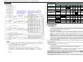
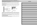
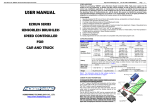
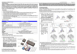
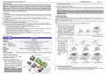
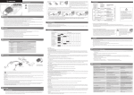
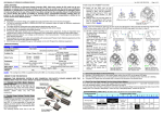
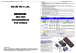
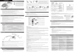
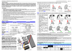
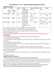
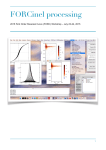
USER MANUAL
eZRun Series
Brushless Speed Controller
for
Rock Crawler / Car / Truck
Declaration
Thanks for purchasing the “eZRun” series Electronic Speed Controller (ESC). High power system for RC
model can be very dangerous, so we strongly suggest you read this manual carefully. In that we have no
control over the correct use, installation, application, or maintenance of our products, no liability shall be
assumed nor accepted for any damages, losses or costs resulting from the use of the product. Any claims
arising from the operating, failure of malfunctioning etc. will be denied. We assume no liability for
personal injury, consequential damages resulting from our product or our workmanship. As far as is
legally permitted, the obligation to compensation is limited to the invoice amount of the affected product.
Features
This product is specially designed for the Rock Crawler, but it is also suitable for normal EP car and truck.
1. Excellent start-up, drag-brake, forward and backward switch, acceleration and linearity features.
2. Compatible with sensorless brushless motor.
3. Use top quality electronic components to enhance the current endurance ability of the ESC.
4. 3 running modes (“Forward/Backward mode” for Rock Crawler, “Forward only with brake” and
“Forward/Backward with brake mode” for normal EP car and truck)
5. 4 steps of maximum reverse force adjustment.
6. Proportional ABS brake function with 4 steps of maximum brake force adjustment, 8 steps of drag-brake force
adjustment and 4 steps of initial brake force adjustment.
7. 9 start modes (Also called “Punch”) from “Level1(Soft)” to “Level9(Very aggressive)”.
8. Multiple protection features: Low voltage cut-off protection for lithium or nickel battery / Over-heat protection /
Throttle signal loss protection / Motor blocked protection.
9. 8 steps of timing adjustment.
10. Waterproof and dustproof.
11. Easily program with only one button and compatible with pocket-sized program card.
Specifications
Model
eZRun-35A-RockCrawler
Cont. Current
Burst Current
Resistance
Suitable Car
Suitable
Brushless Motor
35A
190A
0.0015 ohm
Rock Crawler, 1/10 and 1/12 EP car and truck
For Rock Crawler, the motor is about 32T
For normal EP car and truck, the motor should be more than 9T
4-9 Cell Ni-xx (NiMH or NiCd) or 2-3 Cell Li-Po
1) For 4-6 Cell Ni-xx: You needn’t change the fan combined with the ESC;
2) For 7-9 Cell Ni-xx: You must change the fan combined with the controller because it cannot
work with such a high voltage, so please choose a high voltage fan or supply the fan from the
receiver (+5V); (*Note1)
6V/1.5A
Sensorless Brushless Motor (Diameter: 36mm, Length: 50mm)
31.5* 27.5* 24 (The height of the fan is not included)
30g(Without wires)
Battery
BEC Output
Motor Type
Dimension
Weight
Note1:
For information about the high voltage cooling fan,
please refer to the brief introduction on page 2.
Begin To Use The New ESC
1. Connect the ESC, motor, receiver, battery and servo
according to the following diagram
“+” and “-” wires on the ESC are connected with the battery
pack, and #A, #B and #C are connected with the motor
wires. The “SET” button is used for programming the ESC.
The control cable of the ESC (trio wires with black, red and
white color) is connected with the throttle channel of the
receiver (Usually CH2).
The #A, #B, #C wires of the ESC can be connected with
the motor wires freely (without any order). If the motor runs
in the opposite direction, please swap any two wire
connections.
Note: You can use the transmitter to set the throttle
channel to the “Reverse” direction, and then the motor
will run oppositely. Please calibrate the throttle range
again after changing the direction of throttle channel.
Page - 0 -
User Manual of “eZRun” Series Brushless Speed Controller for Rock Crawler
Ver. HW-13-RC-OEM-081227.1
2. Throttle Range Setting (Throttle Range Calibration)
In order to make the ESC fit the throttle range, you must calibrate it for the following cases; otherwise the ESC
cannot work properly.
1) Begin to use a new ESC;
2) Begin to use a new transmitter;
3) Change the settings of neutral position of the throttle stick, ATV or EPA parameters, etc.
There are 3 points need to be set, they are the top point of “forward”,” backward” and the neutral point.
The following pictures show how to set the throttle range with a FutabaTM transmitter.
A) Switch off the ESC, turn on the transmitter,
set the direction of throttle channel to ”REV”,
set the “EPA/ATV” value of throttle channel to
“100%”, and disable the “ABS” brake function
of your transmitter. (*Note2)
B) Hold the “SET” key and then switch on the
ESC, when the red LED begins to flash,
release the key immediately.
(Please refer to the picture on the right side)
C) Set
the
3
points
according to the steps
shown in the picture on
the right side.
1) Neutral point
2) End point of forward
direction
3) End point of backward
direction
D) When the process of
calibration is finished, the
motor can be started after
3 seconds.
Note2: If you don’t release the “SET” key after the red LED begins to flash, the ESC will enter the program mode,
in such a case, please switch off the ESC and re-calibrate the throttle range again from step A to step D.
3. The LED Status in Normal Running
a) In normal use, if the throttle stick is in the neutral range, neither the red LED nor the green LED lights.
b) The red LED lights when the car is run forward or backward and it will flash quickly when the car is braking.
c) The green LED lights when the throttle stick is moved to the top point (end point) of the forward zone or
backward zone.
Alert Tones
1. Input voltage abnormal alert tone: The ESC begins to check the input voltage when power on, if it is out of the
normal range, such an alert tone will be emitted: “beep-beep-, beep-beep-, beep-beep-” (There is 1 second
time interval between every “beep-beep-” tone).
2. Throttle signal abnormal alert tone: When the ESC can’t detect the normal throttle signal, such an alert tone
will be emitted: “beep-, beep-, beep-” (There is 2 seconds time interval between every “beep-” tone).
Protection Function
1. Low voltage cut-off protection: If the voltage of a lithium battery pack is lower than the threshold for 2 seconds,
the ESC will cut of the output power. Please note that the ESC cannot be restarted if the voltage of each
lithium cell is lower than 3.5V.
For NiMH/NiCd battery packs, if the voltage of the whole NiMH/NiCd battery pack is higher than 9.0V but
lower than 12V, it will be considered as a 3 cell lithium battery pack; If it is lower than 9.0V, it will be
considered as a 2 cell lithium battery pack. For example, if the NiMH battery pack is 8.0V, and the threshold is
set to 2.6V/Cell, so it will be considered as a 2 cell lithium battery pack, and the low-voltage cut-off threshold
for this NiMH battery pack is 2.6*2=5.2V.
2. Over-heat protection: When the temperature of the ESC is higher than a factory-preset value for 5 seconds,
the ESC will cut off the output power. You can disable the over-heat protection function for competition race.
3. Throttle signal loss protection: The ESC will cut off the output power if the throttle signal is lost for 0.2 second.
Trouble Shooting
Trouble
After power on, motor can’t work, no
sound is emitted
After power on, motor can’t work, but
emits “beep-beep-, beep-beep-” alert
tone. (Every “beep-beep-” has a time
interval of 1 second )
After power on, motor can’t work, but
emits “beep-, beep-, beep-” alert tone.
(Every “beep-” has a time interval of
about 2 seconds)
The motor runs in the opposite direction
The motor suddenly stops running
while in working state
Random stop or restart or irregular
working state
Possible Reason
The
connections
between
battery pack and ESC are not
correct
Input voltage is abnormal, too
high or too low.
Solution
Check the power connections
Replace the connectors
Throttle signal is abnormal
Check the transmitter and the
receiver
Check the wire of the throttle
channel
Swap any two wire connections
between the ESC and the motor.
The wire connections between
ESC and the motor need to be
changed
The throttle signal is lost
The ESC has entered the Low
Voltage Protection Mode
Some connections are not
reliable
There is strong Electro Magnetic interference in flying
field.
Check the voltage of the battery
pack
Check the transmitter and the
receiver
Check the wire of the throttle
channel
Replace the battery pack
Check all the connections: battery
pack connections, throttle signal
wire, and motor connections, etc.
Reset the ESC to resume normal
operation. If the function could not
resume, you might need to move to
another area to run the car.
Optional Accessories for Upgrade
We provide the following optional accessories for upgrade your power system:
1. Cooling fan (12V): The high voltage fan is necessary when you are
using battery pack more than 6 cells of NiMH/NiCd. It is located on the heat
sink of the ESC, it helps to cool the ESC with downward airflow. The picture
on the right side shows the installation.
WARNING!
Please note the original fan (5V) combined with the ESC
can ONLY work with a 2 cells lithium battery pack or 4-6 cells NiMH /
NiCd battery pack. Please NEVER use it with a 3 cells lithium battery
pack or NiMH / NiCd battery pack more than 6 cells, otherwise it may be
destroyed.
Please check the label of the fan carefully to confirm its working
voltage before using it.
2. Program card.
Program card is an optional accessory which needs to be purchased
separately. It has a friendly user interface. The process of programming the
ESC becomes quite easy and fast with this pocket sized device. When the
programmable value needs to be changed, please just plug the control wires
of the ESC (trio wires with black, red and white color) into the socket of the
program card (The socket is on the right corner, and marked with + - ),
and then connect the main battery pack to the ESC, each item’s value will be
shown on the program card. Use “ITEM” and “VALUE” buttons to select the
programmable items and new values, and then press “OK” button to store
the new settings into the ESC.
Page - 1 -
User Manual of “eZRun” Series Brushless Speed Controller for Rock Crawler
Ver. HW-13-RC-OEM-081227.1
Program The ESC
Programmable Items list
Programmable
Items
1. Program Method
1
2
Forward Only
with Brake
Forward/Re verse
with Brake
0%
5%
Programmable Value
3
4
5
6
7
8
80%
100%
9
Basic Items
1. Running Mode
2.Drag Brake Force
Forward
and
Reverse
10%
3.Low Voltage
Cut-Off Threshold
NonProtection
2.6V/Cell
2.8V/Cell
4.Start Mod e(Punch)
Level 1
(Soft )
Level 2
Level 3
25%
40%
60%
3.0V
/Cell
3.2V
/Cell
3.4V
/Cell
Level 4 Level 5 Level 6 Level 7 L evel 8
Level 9
Very
aggre ssive
Advanced Items
5.Maximum Brake Force
25%
50%
75%
100%
6.Maximum Reverse Force
25%
50%
75%
100%
7.Initial Brake Force
=Drag Brake
Forc e
0%
20%
40%
8.Neutral Range
6% (Narrow)
9% (Normal)
12% (Wide)
0.00 °
3.75 °
7.50 °
Enable
Disable
9.Timing
(Only for sensorless motor)
10.Ove r-heat Protection
Attention:
11.25 ° 15.00 ° 18.75 °
22.50°
26.25°
The italics texts in the above form are the default settings.
2. Programmable Values
2.1. Running Mode:
►
For rock crawler
Please choose “Forward and Reverse” mode. The backward function in this mode is different from that in
the “Forward/Reverse with Brake” mode because the rock crawler needs an immediate backward action
as soon as the throttle stick is moved to backward zone.
►
For normal EP car and truck
Please choose “Forward with Brake” mode or “Forward/Reverse with Brake” mode. With “Forward with
Brake” mode, the car can go forward and brake, but cannot go backward, this mode is suitable for
competition; “Forward/Reverse with Brake” mode provides backward function, which is suitable for
training.
Note: “Forward/Reverse with Brake” mode uses “Double-Click” method to make the car go
backward. When you move the throttle stick from forward zone to backward zone for the first time, the
ESC begins to brake the motor, the motor speeds down but it is still running, not completely stopped, so
the backward action is NOT happened now. When the throttle stick is moved to the backward zone again
(The 2nd “click”), if the motor speed is slowed down to zero (i.e. stopped), the backward action will be
occurred. The “Double-Click” method can prevent mistakenly reverse when the brake function is
frequently used in steering.
By the way, in the process of braking or reverse, if the throttle stick is moved to forward zone, the motor will regain
forward running at once.
Note:
Ì
In the program process, the motor will emit “Beep” tone at the same time when the LED is flashing.
Ì
If the “N” is bigger than the number “5”, we use a long time flash and long “Beep---” tone to represent
“5”, so it is easy to identify the items of the big number.
2.2. Drag Brake Force: When the throttle stick is moved to the neutral zone, the speed controller will give a
suitable brake force to the motor, we call it “Drag Brake Force”.
►
For rock crawler
The drag brake force for rock crawler is quite strong because the rock crawler needs to lock the wheels
when it is stopped temporarily, otherwise the rock crawler will fall down from the rocks.
►
For normal EP car and truck
The drag brake force for normal EP car and truck is not so strong, normally it should be less than 40%. It
simulates the slight braking effect of a neutral brushed motor while coasting.
For example, if the LED flashes as the following:
“A long time flash + a short time flash” (Motor sounds “Beep---Beep”)
=
“A long time flash + 2 short time flash” (Motor sounds “Beep---BeepBeep”)
the No. 6 item
=
“A long time flash + 3 short time flash” (Motor sounds “Beep---BeepBeepBeep”)
……
And so on.
the No. 7 item
= the No. 8 item
2.3. Low Voltage Cut-Off: The function is mainly to prevent the lithium battery pack from over discharging. When
using lithium battery pack, please set the suitable value for low-voltage protection as your like. WARNING: Never
use the default value “Non-protection” for lithium battery! The ESC monitors the battery’s voltage at any time,
if the voltage is lower than the threshold, the output power will be cut off.
2.4. Start Mode (Also called “Punch”): Select from “Level1 (Soft)” to “Level9 (Very aggressive)” start mode as
your like. Please note that if you choose Level 7 to Level 9 mode, you’d better use good quality battery pack with
Page - 2 -
User Manual of “eZRun” Series Brushless Speed Controller for Rock Crawler
Ver. HW-13-RC-OEM-081227.1
powerful discharge ability, otherwise these 2 modes cannot get the bursting start effect as you want. If the motor
cannot run smoothly (the motor is trembling), it may caused by the weak discharge ability of the battery pack,
please choose a better battery or increase the gear rate.
USER MEMO
2.5. Maximum Brake Force: The ESC provides proportional brake function. The brake force is related to the
position of the throttle stick. Maximum brake force refers to the force when the throttle stick is located at the top
point of the backward zone. A very large brake force can shorten the brake time, but it may damage the gears.
2.6. Maximum Reverse Force: Sets how much power will be applied in the reverse direction. Different value
makes different reverse speed.
2.7. Initial Brake Force: It is also called “minimum brake force”, and it refers to the force when the throttle stick is
located at the initial position of the backward zone. The default value is equal to the drag brake force, so the brake
effect can be very smooth.
2.8. Throttle Neutral Range: Please refer to the following illustrations to adjust the neutral range as your like.
2.9. Timing: There are many differences among structures and parameters of different brushless motors, so a
fixed timing ESC is difficult to compatible with all brushless motors. It is necessary to make the timing value
programmable. Please select the most suitable timing value according to the motor you are just using. Generally,
higher timing value brings out higher power output, but the whole efficiency of the system will be slightly lower
down.
2.10. Over-Heat Protection: If the function is activated, the output power will be cut-off when the temperature of
the ESC is higher than a factory-preset value for more than 5 seconds. When the protection happens, the Green
LED will flash in such a way: “Flashes-----Flashes-----Flashes-----”
3. Reset All Items To Default Values
At any time when the throttle is located in neutral zone (except in the throttle calibration or parameters program
process), hold the “SET” key for over 3 seconds, the red LED and green LED will flash at the same time , which
means each programmable item has be reset to its default value.
Page - 3 -