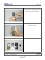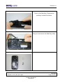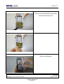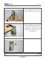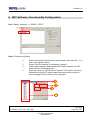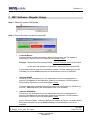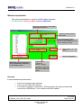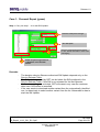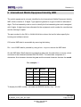
1
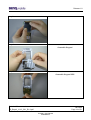
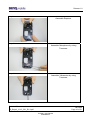
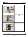
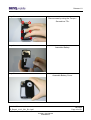
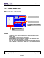
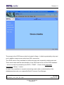
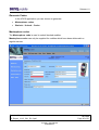
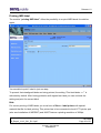
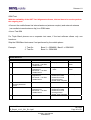
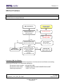
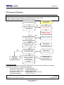
Release 1.0 Service Manual C81 Level 1-3 Release Date Department Notes to change R 1.0 24.04.2006 BenQ Mobile CC S CES New document 04/2006 Technical Documentation TD_Repair_L1-L3_C81_R1.0.pdf Page 1 of 51 Company Confidential 2006©BenQ Release 1.0 Table of Content 1 Key Feature ................................................................................................................................3 2 Unit Description of C81.............................................................................................................4 3 Exploded View of C81 ...............................................................................................................5 4 Disassembly of C81 ..................................................................................................................6 5 Assembly of C81 .....................................................................................................................13 5 BenQ Service Equipment User Manual .................................................................................19 6 GRT Software: Functionality Configuration..........................................................................20 7 GRT Software: Regular Usage ...............................................................................................22 8 JPICS (Java based Product Information Controlling System) ............................................27 9 International Mobile Equipment Identity, IMEI......................................................................33 10 General Testing Information...................................................................................................34 11 Introduction of Service Repair Documentation Level 3 (basic) – C81.............................40 04/2006 Technical Documentation TD_Repair_L1-L3_C81_R1.0.pdf Page 2 of 51 Company Confidential 2006©BenQ Release 1.0 1 Key Feature SIM Card Battery • • Stand – by Time Talking Time Display • • • • • • • • • • Keypad Camera Multimedia/Audio • • • • • • • • • • • • • • • • • • Small (=”Plug In”) 1.8 V or 3 V-SIM card Lition Battery Pack o Nominal Capacity 780mAh o GSM Capacity 750mAh > 250h > 5h 132 x 176 262K colour TFT 1.8 inch hard caps in IMF – technology 12-key-block (0-9,#,*) 2 function keys (SEND, END) ON/OFF key combined with the END key; the symbol ¢ (I inside O) is used as a symbol for ON/OFF 5-way-navi-key 2 soft – keys for different SW-enabled functions 1 dedicated hard key (provider key) white as illumination colour tactile finder on key “5” 6 white LEDs for keypad Integrated 1.3 Mega Pixel camera Integrated camera flash light Three-in-one-earpiece for handset, handsfree and ringing tones Uni-directional microphone Loud signal emitter (soundringer) only for rectangular sound signals Polyphonic ringer tones 64 voices Hands free mode Different selectable volume levels for handsfree, handset and ringer mode MP3 (ringtones and music player), Real Audio 8, MPEG4 AAC/AAC+/AAC++, AMR-NB Audio streaming: AMR-NB, AAC, AAC++, Real Audio 8 64 chords polyphonic ringtones Video resolution: QCIF, subQCIF, decoding: H263, MPEG4, Real Video 8 (available within 2nd SW release); encoding (15fps): H263; streaming: Real Video 8, 3 GPP (H.263, MPEG4) 04/2006 Technical Documentation TD_Repair_L1-L3_C81_R1.0.pdf Page 3 of 51 Company Confidential 2006©BenQ Release 1.0 2 Unit Description of C81 The C81 is designed as a Bar phone with two PCBs. The whole unit consists of a NoIDBlock and parts for the customization. The NoID-Block itself is made of the soldered PCBs and the preassembled upper and lower cases. It is full functional and testable. The parts for the customization are the keypad, the front cover and the battery cover, but only the battery cover will be exchangeable for the end user. All plastic parts are 1 shot molded plastic parts. The Front cover and battery cover are lacquered with high glossy black (Hydra piano black). The Upper casing is lacquered silver. 04/2006 Technical Documentation TD_Repair_L1-L3_C81_R1.0.pdf Page 4 of 51 Company Confidential 2006©BenQ Release 1.0 3 Exploded View of C81 Front Cover preassembly Edge key Imd Lens Keypad Upper case Keypad MMI Modified Minos PCB Battery Nano IO Lower case preassembly: Microphone, Antenna, Vibramotor, Speaker Module Battery Cover 04/2006 Technical Documentation TD_Repair_L1-L3_C81_R1.0.pdf Page 5 of 51 Company Confidential 2006©BenQ Release 1.0 4 Disassembly of C81 All repairs as well as disassembling and assembling have to be carried out in an ESD protected environment and with ESD protected equipment/tools. For all activities the international ESD regulations have to be considered. For more details please check information in c – market https://market.benqmobile.com/SO/welcome.lookup.asp There you can find the document “ESD Guideline”. Step 1 Remove Battery Cover. Step 2 Remove Battery. 04/2006 Technical Documentation TD_Repair_L1-L3_C81_R1.0.pdf Page 6 of 51 Company Confidential 2006©BenQ Release 1.0 Step 3 Step 4 Remove screws by using the Torque – Screwdriver T5+. Step 5 Disconnect Lower Case from Upper Case. 04/2006 Technical Documentation TD_Repair_L1-L3_C81_R1.0.pdf Page 7 of 51 Company Confidential 2006©BenQ Release 1.0 Step 6 To avoid scratches it is mandatory to place a protection foil onto the Display!!! Step 7 Remove MMC Holder. Step 8 04/2006 Technical Documentation TD_Repair_L1-L3_C81_R1.0.pdf Page 8 of 51 Company Confidential 2006©BenQ Release 1.0 Step 9 Remove Vibramotor by using Tweezers. Step 10 Remove Microphone by using Tweezers. Step 11 Remove Earpiece by using the Alternative Opening Tool. 04/2006 Technical Documentation TD_Repair_L1-L3_C81_R1.0.pdf Page 9 of 51 Company Confidential 2006©BenQ Release 1.0 Step 12 Take out the Side Key Connector by pushing it outside the frame. Step 13 Now you can remove the Side Key easily. Step 14 04/2006 Technical Documentation TD_Repair_L1-L3_C81_R1.0.pdf Page 10 of 51 Company Confidential 2006©BenQ Release 1.0 Step 15 Remove the Keypad MMI by using the Alternative Opening Tool. Step 16 Step 17 Remove the Keypad. 04/2006 Technical Documentation TD_Repair_L1-L3_C81_R1.0.pdf Page 11 of 51 Company Confidential 2006©BenQ Release 1.0 Step 18 Remove Display from PCB by using Alternative Opening Tool very carefully. Step 19 Put the Camera Ejector Jig professional through the four edges between the Camera and the Camera Connector. Now push the Ejector Jig and pull out the Camera carefully. Step 20 04/2006 Technical Documentation TD_Repair_L1-L3_C81_R1.0.pdf Page 12 of 51 Company Confidential 2006©BenQ Release 1.0 Overview Upper Parts Upper Case PCB Overview Lower Parts Keypad MMC Display Lower Case Battery Cover Battery Camera Earpiece Vibramotor Microphone Keypad 5 Screws MMC Holder Side Keys Assembly of C81 Step 1 Assemble Camera. Step 2 Assemble Display Module very carefully. 04/2006 Technical Documentation TD_Repair_L1-L3_C81_R1.0.pdf Page 13 of 51 Company Confidential 2006©BenQ Release 1.0 Step 3 Step 4 Assemble Keypad. Step 5 Assemble Keypad MMI. 04/2006 Technical Documentation TD_Repair_L1-L3_C81_R1.0.pdf Page 14 of 51 Company Confidential 2006©BenQ Release 1.0 Step 6 Assemble MMC Holder. Step 7 Assemble the Side Key into the given frame. Step 8 Now fix the Side Key Connector into the Side Key frame. 04/2006 Technical Documentation TD_Repair_L1-L3_C81_R1.0.pdf Page 15 of 51 Company Confidential 2006©BenQ Release 1.0 Step 9 Assemble Earpiece. Step 10 Assemble Microphone by using Tweezers. Step 11 Assemble Vibramotor by using Tweezers. 04/2006 Technical Documentation TD_Repair_L1-L3_C81_R1.0.pdf Page 16 of 51 Company Confidential 2006©BenQ Release 1.0 Step 12 Before assembling the PCB in the Upper Case, it is mandatory to remove the Display Foil! Step 13 Assemble the PCB into the Upper Case. Step 14 Assemble the Lower Case with the before assembled Upper Case. 04/2006 Technical Documentation TD_Repair_L1-L3_C81_R1.0.pdf Page 17 of 51 Company Confidential 2006©BenQ Release 1.0 Step 15 Place screws by using the Torque – Screwdriver T5+. Step 16 Assemble Battery. Step 17 Assemble Battery Cover. 04/2006 Technical Documentation TD_Repair_L1-L3_C81_R1.0.pdf Page 18 of 51 Company Confidential 2006©BenQ Release 1.0 5 BenQ Service Equipment User Manual Introduction Every LSO repairing BenQ handset must ensure that the quality standards are observed. BenQ has developed an automatic testing system that will perform all necessary measurements. This testing system is known as: BenQ Mobile Service Equipment • For disassembling / assembling Torque – Screwdriver Part Number: F 30032 – P 228 – A1 Opening tool (Case opening without destroying) Part Number: F 30032 – P 38 – A1 Alternative Opening tool Part Number: F30032 – P583 – A1 Tweezers Camera Ejector Tool Professional Part Number: F30032 – P514 – A1 • For testing All mobile phones have to be tested with the GRT – Software. The service partner is responsible to ensure that all required hardware is available. For additional Software and Hardware options as well as the supported GRT equipment, please check the GRT User manual. 04/2006 Technical Documentation TD_Repair_L1-L3_C81_R1.0.pdf Page 19 of 51 Company Confidential 2006©BenQ Release 1.0 6 GRT Software: Functionality Configuration Sep 1: Select „Settings >> SWUP / JPICS” Step 2: Proceed as follows: ¾ ¾ ¾ ¾ Select all required Variants you need to repair (click onto the “+” in front of the product name. Check Com-Port setting. If necessary change it Check speed setting. Select always the lowest speed if your PC does not have a fast serial card Enter the value for “JPICS Server Timeout”. Be careful, this value defines how long GRT tries to reach the server until you get an error message. Do not select a very long time 2 3 4 1 04/2006 Technical Documentation TD_Repair_L1-L3_C81_R1.0.pdf Page 20 of 51 Company Confidential 2006©BenQ Release 1.0 Step 3: Connect to GRM Server • Choose in the section „GRM” the „Connect to GRM Database“ functionality 1 2 3 • Enter your GRT-Username and Password into this fields Activate always both boxes if you connect to the database. Start with “Connect” It you IT infrastructure parameter have changed, use this button to move to the configuration mask End the connection with a click onto the „Exit button“ (appearing after successful data exchange) GRT Software has now finished all required settings and configuration tasks. All files have been down- and uploaded. In dependency of the selected number of mobile phones and variants the volume of transferred date could be (~100MB) 04/2006 Technical Documentation TD_Repair_L1-L3_C81_R1.0.pdf Page 21 of 51 Company Confidential 2006©BenQ Release 1.0 7 GRT Software: Regular Usage Step 1: Select the section SWUpdate Step 2: Choose the area you want to work with • Personal Repair Personal Repair is always accessible. Basis for the decision if a SW-Update is authorised by Siemens is the so called Service Release-Table. Example: Mobile Phone has already SW50. Service -Release-Table shows SW50 In this case SW-Update is not necessary and therefore not authorized In any case customer data can be erased on request. (xfs and mapping have to be activated) Of course JPICS hardware and authorisation have to be available. • Operator SWAP This area is only accessible if you are released by the service management to perform SW-Updates for Net-Operators. Basis for the decision if a SW-Update is authorised by Siemens is the so called Master-Table. Customer data will be erased without any exception and any chance to influence by the user. JPICS hardware and authorisation have to be available. • Operator SWUpdate This area is only accessible if you are released by the service management to perform SW-Updates for Net-Operators. Basis for the decision if a SW-Update is authorised by Siemens is the so called Master-Table. Like in “Personal Repair” customer data can be erased on request. (xfs and mapping have to be activated) Of course JPICS hardware and authorisation have to be available. 04/2006 Technical Documentation TD_Repair_L1-L3_C81_R1.0.pdf Page 22 of 51 Company Confidential 2006©BenQ Release 1.0 Window explanation This general explanation is valid for all SW-Update channels (Personal Repair, Operator SWAP, Operator SWUpdate) After using „Check Variant“ Phone IMEINumber will be shown here Window to select the mobile phone CPU Shows the different SW –Versions a) SW inside the mobile phone b) Version of Service Release Table SW c) Version of Master Table SW Start button Update for SW- Stop / leave SW-Update Automatic read out function of phone type/Variant. Appearing in the window above. Select boxes for: Content = xfs Settings = mapping Attention: Activation of the boxes will cause erase of customer date while SWUpdate Remarks: In case of malfunction please check o Is the correct phone type selected o Is the correct COM-Port selected o If a variant is missing, move back to Settings select the missing variant and conncet the GRM Server. Then continue with SW-Update. 04/2006 Technical Documentation TD_Repair_L1-L3_C81_R1.0.pdf Page 23 of 51 Company Confidential 2006©BenQ Release 1.0 Case 1: Personal Repair (green) Step 1: Carry out step 1 – 4 to start SW-Update. 1 4 3 2 Select the mobile phone CPU type Start SW-Update Choose if customer data shall be erased. If “Yes” activate the boxes in front of xfs and mapping Read out phone type/Variant. >>Appears in the window above. Remarks: - The decision about a Siemens authorised SW-Update depends only on the Service Release-Table . The SW which is booted by GRT can be below the SW mentioned in the Service Release Table, if this SW is not released for the Net-Operator If xfs and mapping are activated, GRT will erase in any case the customer data even if the action is cancelled. If the user wants to download another variant then the automatically identified one, he has simply to select another variant from the list. Afterwards he has to start the SW-Update 04/2006 Technical Documentation TD_Repair_L1-L3_C81_R1.0.pdf Page 24 of 51 Company Confidential 2006©BenQ Release 1.0 Case 2: Operator SWAP (red) Step 1: Carry out step 1 – 4 to start SW-Update. 1 4 3 2 Select the mobile phone CPU type Start SW-Update Choose if customer data shall be erased. If “Yes” activate the boxes in front of xfs and mapping Read out phone type/Variant. >>Appears in the window above. Remarks: - The decision about a Siemens authorised SW-Update depends only on the Master-Table . The user has no chance to influence the decision Xfs and mapping are always activated there is no chance to deactivate them. GRT will erase in any case the customer data even if the action is cancelled. If the user wants to download another variant then the automatically identified one, he has simply to select another variant from the list. Afterwards he has to start the SW-Update 04/2006 Technical Documentation TD_Repair_L1-L3_C81_R1.0.pdf Page 25 of 51 Company Confidential 2006©BenQ Release 1.0 Case 3 Operator SWUpdate (blue) Step 1: Carry out step 1 – 4 to start SW-Update. 1 4 3 2 Select the mobile phone CPU type Start SW-Update Choose if customer data shall be erased. If “Yes” activate the boxes in front of xfs and mapping Read out phone type/Variant. >>Appears in the window above. Remarks: - The decision about a Siemens authorised SW-Update depends only on the Master-Table . The user has no chance to influence the decision Xfs and mapping can be activated on demand. GRT will erase in any case the customer data even if the action is cancelled. If the user wants to download another variant then the automatically identified one, he has simply to select another variant from the list. Afterwards he has to start the SW-Update 04/2006 Technical Documentation TD_Repair_L1-L3_C81_R1.0.pdf Page 26 of 51 Company Confidential 2006©BenQ Release 1.0 8 JPICS (Java based Product Information Controlling System) Overview The following functions are available for the LSO: • General mobile information • Generate PINCODE • Generate SIMLOCK – UNLOCK – Code • Print IMEI labels 04/2006 Technical Documentation TD_Repair_L1-L3_C81_R1.0.pdf Page 27 of 51 Company Confidential 2006©BenQ Release 1.0 The access to the JPICS server which is located in Kamp – Lintfort is protected by chip card and in addition using secure socket layer (SSL) connection. The JPICS server is only available for authorized users with a specially coded smart card. These smart cards and the administration of the JPICS web server and the PICS database – server can only be provided by the JPICS – TRUST – Center of the responsible department in Kamp – Lintfort. In case of any questions or requests concerning smart cards or administration of the databases please ask your responsible BenQ Customer Care Manager. 04/2006 Technical Documentation TD_Repair_L1-L3_C81_R1.0.pdf Page 28 of 51 Company Confidential 2006©BenQ Release 1.0 Installation overview The following installation description assumes that a web browser is already installed. JPICS is tested with the following browsers: 1. Internet Explorer Version 5.5 and higher 2. Netscape Version 6 and higher For further information regarding supported browsers, browser version and supported operating systems, see the Sun FAQ’s. Here is a step by step instruction to install all the required components: It is necessary to follow this order! 1. Smart Card Reader (Omnikey: Cardman 2020 USB or Cardman 3121 USB) 2. CardOS interface (Siemens Version 3.0 B) 3. Java Runtime Environment (Sun) 4. Java additional components Every user is responsible for a proper installation matching the license agreements. For installation and further access you need the following: 1. The JPICS Installation – CD 2. The Smart Card JPICS. Remark: We recommend using Cardman 2020 USB or Cardman 3121 USB. Serial card readers are not supported!!! 04/2006 Technical Documentation TD_Repair_L1-L3_C81_R1.0.pdf Page 29 of 51 Company Confidential 2006©BenQ Release 1.0 Generate Codes In the JPICS application you can choose to generate: • Masterphone codes • Simlock – Unlock – Codes Masterphone codes The Masterphone code is used to unlock blocked mobiles. Masterphone codes can only be supplied for mobiles which have been delivered in a regular manner. 04/2006 Technical Documentation TD_Repair_L1-L3_C81_R1.0.pdf Page 30 of 51 Company Confidential 2006©BenQ Release 1.0 Simlock – Unlock – Code The Simlock – Unlock – Codes can only be generated if the following conditions are given: • Mobile must have an active Simlock inside. • The user must be given the authorization to obtain Simlock – Unlock – Codes for the variant of the operator to which the mobile was delivered last time. 04/2006 Technical Documentation TD_Repair_L1-L3_C81_R1.0.pdf Page 31 of 51 Company Confidential 2006©BenQ Release 1.0 Printing IMEI label The module “printing IMEI label” offers the possibility to re-print IMEI labels for mobiles again. You are able to print 1 label in just one step. To prevent that misaligned labels are being printed, the setting “Print test labels = 9” is activated by default. After having printed a well aligned test label you can uncheck the setting and print the correct label. Hint: For correct printing of IMEI labels you must have a Zebra – label printer with special material that fits for label printing. This printer has to be connected to local LPT1 printer port (also see Installation of IMPRINT) and MUST feature a printing resolution of 300dpi. 04/2006 Technical Documentation TD_Repair_L1-L3_C81_R1.0.pdf Page 32 of 51 Company Confidential 2006©BenQ Release 1.0 9 International Mobile Equipment Identity, IMEI The mobile equipment is uniquely identified by the International Mobile Equipment Identity, IMEI, which consists of 15 digits. Type approval granted to a type of mobile is allocated 6 digits. The final assembly code is used to identify the final assembly plant and is assigned with 2 digits. 6 digits have been allocated for the equipment serial number for manufacturer and the last digit is spare. The part number for the C81 is S30880-S3330-#xxx where the last for letters specify the housing and software variant. C81 series IMEI label is accessible by removing the battery. Re – use of IMEI label is possible by using a hair – dryer to remove the IMEI label. On this IMEI label, BenQ has also includes the data code for production or service, which conforms to the industrial standard DIN EN 60062. The data code comprises of 2 characters: first character denotes the year and the second character denotes the month. For example: S5 CODE Year Month CODE P 2002 MARCH 3 R 2003 APRIL 4 S 2004 MAY 5 T 2005 JUNE 6 U 2006 JULY 7 To display the IMEI number, exit code and SW/HW version, key: * # 0 6 # 04/2006 Technical Documentation TD_Repair_L1-L3_C81_R1.0.pdf Page 33 of 51 Company Confidential 2006©BenQ Release 1.0 10 General Testing Information General Information The technical instruction for testing GSM mobile phones is to ensure the best repair quality. Validity This procedure is to apply for all from BenQ mobile authorized level 2 up to 3 workshops. Procedure All following checks and measurements have to be carried out in an ESD protected environment and with ESD protected equipment/tools. For all activities the international ESD regulations have to be considered. Get delivery: ¾ Ensure that every required information like fault description, customer data a.s.o. is available. ¾ Ensure that the packing of the defective items is according to packing requirements. ¾ Ensure that there is a description available, how to unpack the defective items and what to do with them. Enter data into your database: (Depends on your application system) ¾ Ensure that every data, which is required for the IRIS-Reporting is available in your database. ¾ Ensure that there is a description available for the employees how to enter the data. 04/2006 Technical Documentation TD_Repair_L1-L3_C81_R1.0.pdf Page 34 of 51 Company Confidential 2006©BenQ Release 1.0 Incoming check and check after assembling: !! Verify the customers fault description!! ¾ After a successful verification pass the defective item to the responsible troubleshooting group. ¾ If the fault description can not be verified, perform additional tests to save time and to improve repair quality. - Switch on the device and enter PIN code if necessary unblock phone. - Check the function of all keys including side keys. - Check the display for error in line and row, and for illumination. - Check the ringer/loudspeaker acoustics by individual validation. - Perform a GSM Test as described on page 36. Check the storage capability: ¾ Check internal resistance and capacity of the battery. ¾ Check battery charging capability of the mobile phone. ¾ Check charging capability of the power supply. ¾ Check current consumption of the mobile phone in different mode. Visual inspection: ¾ Check the entire board for liquid damages. ¾ Check the entire board for electrical damages. ¾ Check the housing of the mobile phone for damages. SW update: ¾ Carry out a software update and data reset according to the master tables and operator/customer requirements. Repairs: The disassembling as well as the assembling of a mobile phone has to be carried out by considering the rules mentioned in the dedicated manuals. If special equipment is required the service partner has to use it and to ensure the correct function of the tools. If components and especially soldered components have to be replaced all rules mentioned in dedicated manuals or additional information e.g. service information have to be considered 04/2006 Technical Documentation TD_Repair_L1-L3_C81_R1.0.pdf Page 35 of 51 Company Confidential 2006©BenQ Release 1.0 GSM Test: With the availability of the GRT Test /Alignment software, this tool has to be used to perform the outgoing test! >Connect the mobile/board via internal antenna (antenna coupler) and external antenna (car cradle/universal antenna clip) to a GSM tester >Use a Test SIM For Triple Band phones use a separate test case, if the test software allows only one handover. Skip the GSM Band test cases if not performed by the mobile phone Example: 1. Test file 2. Test file Band 1 = GSM900 / Band 2 = GSM1800 Band 1 = GSM1900 Internal Antenna Test case 1 Location Update 2 Call from BS 3 TX GSM Band 1 4 5 Handover to GSM Band 2 Including Handover Check TX GSM Band 2 6 Call release from BS Parameter • GSM Band 1 • BS Power = -55 dBm • middle BCCH • low TCH • highest PCL • BS Power = -75 dBm • middle BCCH • low TCH • highest PCL • BS Power = -75 dBm • middle BCCH • low TCH • highest PCL0 • BS Power = -75 dBm • middle BCCH Measurements • Display check Limits • individual check • Ringer/Loudspeaker check • individual check • Frequency Error • Phase Error RMS • Phase Error Peak • Average Power • Power Time Template • GSM Spec. • Frequency Error • Phase Error RMS • Phase Error Peak • Average Power • Power Time Template • GSM Spec. 04/2006 Technical Documentation TD_Repair_L1-L3_C81_R1.0.pdf Page 36 of 51 Company Confidential 2006©BenQ Release 1.0 External Antenna 7 Call from MS 8 TX GSM Band 1 9 RX GSM Band 1 10 11 Handover to GSM Band 2 Including Handover Check TX GSM Band 2 12 RX GSM Band2 13 Call release from MS • GSM900 • high TCH • second highest PCL • BS Power = -75 dBm • middle BCCH • high TCH • second highest PCL • BS Power = -75 dBm • middle BCCH • high TCH • BS Power = -102 dBm • 50 Frames • middle BCCH • high TCH • second highest PCL • BS Power = -75 dBm • middle BCCH • high TCH • BS Power = -102 dBm • 50 Frames • middle BCCH • Keyboard check • individual check • Frequency Error • Phase Error RMS • Phase Error Peak • Average Power • Power Time Template • RX Level • RX Qual • BER Class Ib • BER Class II • BER Erased Frames • GSM Spec. • Frequency Error • Phase Error RMS • Phase Error Peak • Average Power • Power Time Template • RX Level • RX Qual • BER Class Ib • BER Class II • BER Erased Frames • GSM Spec. • GSM Spec. • GSM Spec. Final Inspection: The final inspection contains: 1) A 100% network test (location update, and set up call). 2) Refer to point 3.3. 3) A random sample checks of: - Data reset (if required) - Optical appearance - complete function 4) Check if PIN-Code is activated (delete the PIN-Code if necessary). Basis is the international standard of DIN ISO 2859. Use Normal Sample Plan Level II and the Quality Border 0,4 for LSO. Remark: All sample checks must be documented. 04/2006 Technical Documentation TD_Repair_L1-L3_C81_R1.0.pdf Page 37 of 51 Company Confidential 2006©BenQ Release 1.0 Annex 1 Test SIM Card There are two different “Test SIM Cards” in use: 1) Test SIM Card from the company “ORGA” Pin 1 number: PUK 1 : 0000 12345678 Pin 2 number: PUK 2 : 0000 23456789 2) Test SIM Card from the company “T-D1” Pin 1 number: PUK : 1234 76543210 Pin 2 number: PUK 2 : 5678 98765432 04/2006 Technical Documentation TD_Repair_L1-L3_C81_R1.0.pdf Page 38 of 51 Company Confidential 2006©BenQ Release 1.0 Annex 2 Battery Date Code overview Varta Date code example N 9 A VA Year (N:2001, O:2002...) Month (1:Jan, 2:Feb,…9:Sep, O:Oct, N:Nov, D:Dec) Revision Letter (A, B,…) Hitachi / Maxwell Date code example Supplier Code (Maker’s marking) N 9 A MX Year (N:2001, O:2002...) Month (1:Jan, 2:Feb,…9:Sep, O:Oct, N:Nov, D:Dec) Revision Letter (A, B,…) Sanyo Date code example Supplier Code (Maker’s marking) N 9 A SY Year (N:2001, O:2002...) Month (1:Jan, 2:Feb,…9:Sep, O:Oct, N:Nov, D:Dec) Revision Letter (A, B,…) NEC Date code example Supplier Code (Maker’s marking) N 8 A NT Year (N:2001, O:2002...) Month (1:Jan, 2:Feb,…9:Sep, O:Oct, N:Nov, D:Dec) Revision Letter (A, B,…) Panasonic Date code example Supplier Code (Maker’s marking) O N A PAN Year (N:2001, O:2002...) Month (1:Jan, 2:Feb,…9:Sep, O:Oct, N:Nov, D:Dec) Revision Letter (A, B,…) Sony Date code example Supplier Code (Maker’s marking) P N A SO Year (O:2002, P:2003...) Month (1:Jan, 2:Feb,…9:Sep, O:Oct, N:Nov, D:Dec) Revision Letter (A, B,…) Supplier Code (Maker’s marking) 04/2006 Technical Documentation TD_Repair_L1-L3_C81_R1.0.pdf Page 39 of 51 Company Confidential 2006©BenQ Release 1.0 11 Introduction of Service Repair Documentation Level 3 (basic) – C81 Purpose This part of Service Repair Documentation is intended to carry out repairs on BenQ Mobile repair level 3basic (only for workshops without level 3 equipment (special agreement required). The described failures shall be repaired in BenQ authorized local workshops only. The level 3basic partners are obliged to send exchanged boards (SWAP) to the next higher Service Repair Partner. All repairs have to be carried out in an ESD protected environment and with ESD protected equipment/tools. For all activities the international ESD regulations have to be considered. Assembling/disassembling has to be done according to the latest C81 Level 1-3 repair documentation. The Service Partner has to ensure that every repaired mobile Phone is checked according to the latest released General Test Instruction document (both documents are available in the Technical Support section of the C-market). Check at least weekly C-market for updates and consider all C81 related Customer Care Information C81 Partnumber on IMEI label: S30880-S3330-#xxx , while # may be any letter (A-Z) and xxx may be any number from 100, 101, 102.... Scrap Handling: All Scrap information given in this manual are related to the SCRAP-Rules and instructions. Attention: Consider the new "LEAD-FREE" soldering rules (available in the communication market), avoid excessive heat. Scope This document is the reference document for all BenQ mobile authorised Service Partners which are released to repair BenQ mobile phones up to level 3basic. Terms and Abbreviations 04/2006 Technical Documentation TD_Repair_L1-L3_C81_R1.0.pdf Page 40 of 51 Company Confidential 2006©BenQ Release 1.0 List of available Level 3 (basic) parts Product C81 C81 C81 C81 C81 C81 C81 C81 C81 ID X1400 X1504 X1604 X2200 X2705 X3500 X3800 X4800 Z1601 Order Number L36334-Z97-C213 L50634-Z93-C364 L36334-Z97-C337 L50634-Z97-C380 L50634-Z97-C363 L50634-Z97-C516 L36334-Z93-C297 L50634-Z97-C348 L50620-U6029-D670 Description CM CONNECTOR BATTERY 3-POL IO-JACK NANO 12-POL CONNECTOR SIM CARD READER K1 CONNECTOR DISPLAY 20POL CONNECTOR BOARD TO BOARD 14-POL. X75 CONNECTOR HYDRA-CAMERA-SOCKET CONNECTOR ANTENNA 6mm CONNECTOR RS-MMC-READER X75 FILTER EMI (Fi-Type6) PB Free Hardware requirements (According to General soldering information V1.3 - check C-market for updates) Jigs, Tools and working materials for all described repairs: hot air blower soldering gun tweezers flux solder 04/2006 Technical Documentation TD_Repair_L1-L3_C81_R1.0.pdf Page 41 of 51 Company Confidential 2006©BenQ Release 1.0 C81 Board Layout Upper board side Display Connector B to B Connector RS MMC Reader Lower Board Side Camera Connector SIM Card Reader EMI Filter Nano IO Connector RF Antenna Connector Battery Connector 04/2006 Technical Documentation TD_Repair_L1-L3_C81_R1.0.pdf Page 42 of 51 Company Confidential 2006©BenQ Release 1.0 SIM Card Problems Fault Symptoms Customer: Handset does not accept SIM card Back to customer without repair SIM Card Problems Watch for oxidation and damaged pads of the SIM Card reader Not okay Caused by customer SCRAP - has to be send separately to WSC Okay Not okay - check for twisted or bent contacts - check for dry joints Check the status of the SIM Card reader visually Okay Exchange SIM Card reader Not okay Use the resistor test function of a multimeter to check connection between spring contacts and soldering contacts. The value must be ~0Ω Okay Continue with higher repair level Connector SIM Card Reader Use soldering iron to remove defective component. Avoid excessive heat! Watch surrounding components! Resolder new component afterwards. E-commerce order number: L50634-Z97-C458 E-commerce order name: CONNECTOR SIM CARD READER R65 SHORT Soldering temperature: ~ 360°C TIP Temp. 11/2005 Technical Documentation TD_Repair_L1-L3_C81_R1.0.pdf Page 43 of 51 Company Confidential 2005©BenQ Release 1.0 I/O Connector Problems Fault Symptoms Customer: Problems with external loudspeaker or microphone when using a car kit Problems with accessories connected at the IO connector Back to customer without repair IO connector Problems Watch for oxidation and damaged pads of the IO connector Not okay Caused by customer SCRAP - has to be send separately to WSC Okay Not okay Clean IO connector Check the dust inside the IO connector Okay Not okay Exchange the damaged Filter Check the status of the EMI Filter visually Okay Not okay Exchange IO connector - check for twisted or bent contacts - check for dry joints Check the status of the IO connector visually Not okay Use the resistor test function of a multimeter to check connection between spring contacts and soldering contacts. The value must be ~0Ω Okay Continue with higher repair level Connector IO Jack Use soldering iron to remove defective component. Avoid excessive heat! Watch surrounding components! Resolder new component afterwards. E-commerce order number: L50634-Z93-C364 E-commerce order name: IO-JACK NANO 12-POL E-commerce order number: L50620-U6029-D670 E-Commerce name: FILTER EMI (Fi-Type6) PB Free Soldering temperature: ~ 360°C TIP Temp. 11/2005 Technical Documentation TD_Repair_L1-L3_C81_R1.0.pdf Page 44 of 51 Company Confidential 2005©BenQ Release 1.0 Board to Board Connector Problems Fault Symptoms Customer: GRT: Display problems Keypad illumination problems Keypad malfunction Keypad malfunction Current measured failed Back to customer without repair B to B connector problems Watch for oxidation and damaged pads of the B to B connector not okay okay not okay Check the status of the B to B connector visually caused by customer SCRAP - has to be send separately to WSC - check for twisted or bent contacts - check for dry joints okay Exchange B to B connector not okay Continue with higher repair level Connector BOARD TO BOARD Use soldering iron/hot air blower to remove defective component. Avoid excessive heat! Watch surrounding components! Resolder new component afterwards. E-commerce order number: L50634-Z97-C461 E-commerce order name: CONNECTOR BOARD TO BOARD 40-POL 1,5MM E-commerce order number: L50697-F5008-F306 E-commerce order name: CONNECTOR BOARD TO BOARD 16-POL E-commerce order number: L50634-Z97-C460 E-commerce order name: CONNECTOR BOARD TO BOARD 40-POL 1MM Soldering temperature: ~ 360°C TIP Temp. 11/2005 Technical Documentation TD_Repair_L1-L3_C81_R1.0.pdf Page 45 of 51 Company Confidential 2005©BenQ Release 1.0 Battery Connector Problems Fault Symptoms Customer: GRT: Mobile does not switch on No connection to GRT Back to customer without repair Battery connector problems Watch for oxidation and damaged pads of the battery connector Not okay Okay Not okay Caused by customer SCRAP - has to be send separately to WSC - check for twisted or bent contacts - check for dry joints Check the status of the battery connector visually Okay Exchange battery connector Not okay Use the resistor test function of a multimeter to check connection between spring contacts and soldering contacts. The value must be ~ 0Ω. Okay Continue with higher repair level Connector BATTERY Use hot air blower to remove defective component. Avoid excessive heat! Watch surrounding components! Resolder new component afterwards. E-commerce order number: L50634-Z97-C482 E-Commerce name: CONNECTOR BATTERY 3-POL X85-2 Soldering temperature: 240 - 255°C 11/2005 Technical Documentation TD_Repair_L1-L3_C81_R1.0.pdf Page 46 of 51 Company Confidential 2005©BenQ Release 1.0 Camera Connector Problems Fault Symptoms Customer: Camera malfunction Back to customer without repair Camera connector Problems not okay Watch for oxidation and damaged pads of the camera connector caused by customer okay not okay SCRAP - has to be send separately to WSC - check for twisted or bent contacts - check for dry joints Check the status of the camera connector visually not okay Exchange camera connector Use the resistor test function of a multimeter to check connection between spring contacts and soldering contacts. The value must be ~0Ω okay Continue with higher repair level Connector CAMERA Use hot air blower to remove defective component. Avoid excessive heat! Watch surrounding components! Resolder new component afterwards. E-commerce order number: L50634-Z97-C634 E-commerce order name: CONN AXK7L30227 Soldering temperature: ~ 360°C TIP Temp. 11/2005 Technical Documentation TD_Repair_L1-L3_C81_R1.0.pdf Page 47 of 51 Company Confidential 2005©BenQ Release 1.0 Display Problems Fault Symptoms Customer: Display problems GRT: Current measured failed Back to customer without repair Display Problems Watch for oxidation and damaged pads of the Display connector not okay okay not okay SCRAP - has to be send separately to WSC - check for twisted or bent contacts - check for dry joints Check the status of the Display connector visually not okay Exchange display connector Use the resistor test function of a multimeter to check connection between spring contacts and soldering contacts. The value must be ~0Ω caused by customer okay Continue with higher repair level Connector DISPLAY Use hot air blower to remove defective component. Avoid excessive heat! Watch surrounding components! Resolder new component afterwards. E-commerce order number: L50634-Z97-C635 E-commerce order name: CONN AXK734245 Soldering temperature: ~ 360°C TIP Temp. 11/2005 Technical Documentation TD_Repair_L1-L3_C81_R1.0.pdf Page 48 of 51 Company Confidential 2005©BenQ Release 1.0 RF Antenna Problems Fault Symptoms Customer: GRT: Network search No location update possible Failure by TX/RX measurements No location update possible Back to customer without repair RF connector Problems Not okay Watch for oxidation and damaged pads of the RF connector Caused by customer SCRAP - has to be send separately to WSC Okay Not okay Clean RF connector Check the dust inside the RF connector Okay Not okay - check for twisted or bent contacts - check for dry joints Check the status of the RF connector visually Okay Exchange RF connector Not okay Use the resistor test function of a multimeter to check connection between input and output contacts. The value must be ~0Ω Okay Continue with higher repair level Connector RF Use hot air blower to remove defective component. Avoid excessive heat! Watch surrounding components! Resolder new component afterwards. E-commerce order number: L50634-Z97-C554 E-commerce name: CONN ANT RF05301-PG E-commerce order number: L50615-Z77-C287 E-commerce name: SWI RF ANTENNA MS-147 Soldering temperature: 240 - 255°C 11/2005 Technical Documentation TD_Repair_L1-L3_C81_R1.0.pdf Page 49 of 51 Company Confidential 2005©BenQ Release 1.0 RS - MMC Connector Problems Fault Symptoms Customer: MMC malfunction Back to customer without repair MMC connector problems Watch for oxidation and damaged pads of the MMC connector not okay caused by customer okay not okay SCRAP - has to be send separately to WSC - check for twisted or bent contacts - check for dry joints Check the status of the MMC connector visually okay Exchange MMC connector not okay Use the resistor test function of a multimeter to check connection between spring contacts and soldering contacts. The value must be ~0Ω okay Continue with higher repair level Connector MMC Use soldering iron to remove defective component. Avoid excessive heat! Watch surrounding components! Resolder new component afterwards. E-commerce order number: L50634-Z97-C415 E-commerce order name: CONNECTOR RS MMC X75; CONNECTOR RS MMC X75 Soldering temperature: ~ 360°C TIP Temp. Attention: Avoid excessive heat in order not to damage the plastic material of the connector 11/2005 Technical Documentation TD_Repair_L1-L3_C81_R1.0.pdf Page 50 of 51 Company Confidential 2005©BenQ Release 1.0 EMI Filter Problems Fault Symptoms Customer: No Data Connectivity via I/O Connector GRT: No Software Update possible Get Mobile Info Fails Back to customer without repair EMI Filter Problems Watch for oxidation and damaged pads of the EMI Filter Not okay Okay Not okay Check the status of the EMI Filter visually Caused by customer SCRAP - has to be send separately to WSC - check for dry joints Okay Exchange the EMI Filter Continue with higher repair level EMI Filter Use soldering iron to remove defective component. Avoid excessive heat! Watch surrounding components! Resolder new component afterwards. E-commerce order number: L50620-U6029-D670 E-Commerce name: FILTER EMI (Fi-Type6) PB Free Soldering temperature: ~ 360°C TIP Temp. 11/2005 Technical Documentation TD_Repair_L1-L3_C81_R1.0.pdf Page 51 of 51 Company Confidential 2005©BenQ