1
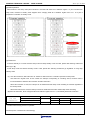
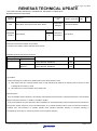
Date: Apr. 23, 2015
RENESAS TECHNICAL UPDATE
1753, Shimonumabe, Nakahara-ku, Kawasaki-shi, Kanagawa 211-8668 Japan
Renesas Electronics Corporation
Product
Category
Title
MPU/MCU
Document
No.
TN-RZ*-A003A/E
RZ/A Series: Notes about Power-Down Modes
Information
Category
Technical Notification
Reference
Document
See following
Rev.
1.00
Lot No.
Applicable
Product
See following
All
In RZ/A1H Group, RZ/A1M Group, and RZ/A1L Group, a bug about Power-Down Modes is found.
Notes about Power-Down Modes are as follows.
According to this update, relevant manuals will be revised.
Applicable products and relevant documents
Applicable products
series
Group
RZ/A
RZ/A1L
RZ/A1M(Note),
RZ/A1H
Relevant documents
RZ/A1L Group
User’s Manual: Hardware
RZ/A1H Group
User’s Manual: Hardware
Rev.
Rev
1.00
Rev
1.00
Document number
R01UH0437EJ0100
R01UH0403EJ0100
(Note) RZ/A1M is planned to be added in the next revision of User’s Manual.
[1] Condition
If both of following two conditions are satisfied when Power-Down Modes is used.
1)
Both “sleep mode” and “software standby mode or deep standby mode (referred as “standby mode” if there is no need
to distinguish two modes)” is used.
2)
WFI instruction is used to transition to the sleep mode.
[2] Phenomenon
There is possibility that the transition to the standby mode happens before execution of expected instructions, which is placed
after the instruction which set 1 to STBY bit of STBCR1 register.
It may cause problem on system operation: When preparation for cancelling standby mode is included in these instructions to
be executed, standby mode may not be canceled properly. Or, if software standby mode is used, as instruction execution is
re-started from next instruction of software standby mode transition instruction following to exception handling of
corresponding cancel source, re-start may result in incorrect system operation.
(c) 2015. Renesas Electronics Corporation. All rights reserved.
Page 1 of 4
Date: Apr. 23, 2015
RENESAS TECHNICAL UPDATE TN-RZ*-A003A/E
[3] Detail explanation
After transition to the sleep mode (WFI instruction is executed with STBY bit of STBCR1 register = 0) and canceled from
sleep mode, transition to standby mode happens when changing STBY bit of STBCR1 register from 0 to 1 as a part of
preparation of transition to standby mode.
[4] Workaround
If software standby is not used and both sleep mode and deep standby mode are used, please take following workaround
either (A) or (B).
If both sleep mode and software standby mode is used, please take following workaround (A) regardless of using deep
standby mode.
(A) Use “SEV instruction, WFE instruction x2” instead of “WFI instruction” In transition operation to sleep mode.
And ARM CPU register must be set unmask the interrupt corresponding to cancelling source, because there is
functional difference between WFI instruction and WFE instruction.
When WFI instruction is used, the interrupt can be masked because sleep mode cancelling is executed regardless of
the interrupt mask.
When WFE instruction is used, the interrupt cannot be masked because it also masks sleep mode cancelling.
(B) Place the instruction, which changes STBY bit of STBCR1 register from 0 to 1, immediately before WFI instruction.
Power-Down Modes
Sleep mode
Use case
Software standby mode
combination
Deep standby mode
Workaround
Not use
use
Unnecessary
use
Either
(A)
use
Not use
use
(A) or (B)
Not use
Not use
Unnecessary *1
*1: if take workaround (A), there is no problem.
Detail sequence of workaround is described [5].
Page 2 of 4
RENESAS TECHNICAL UPDATE TN-RZ*-A003A/E
Date: Apr. 23, 2015
[5] Revised contents of user’s manual.
In order to reflect this workaround, we will revise the user's manual as follows. (Chapter number, page number is one of
user's manual of RZ/A1H.)
[5-1] revision contents for workaround (A)
[UM revision point]
55.3.1 Sleep Mode (42.3.1 for RZ/A1L)
(1) Transition to Sleep Mode
<Before revision>
Executing the WFI instruction when the STBY bit in STBCR1 is 0 causes a transition from the program execution state to sleep
mode. Although the CPU halts immediately after executing the WFI instruction, the contents of its internal registers remain
unchanged. The on-chip peripheral modules continue to run in sleep mode. The clock output from the CKIO pin is continued.
<After revision>
When causing the device to make a transition from the program execution state to sleep mode, follow procedure (a) or (b)
depending on the condition described following the description of the procedures.
(a) Execute the WFI instruction while the STBY bit in STBCR1 is 0.
(b) While the STBY bit in STBCR1 is 0 and bits I and F in the current program status register (CPSR) corresponding to the
interrupt source to trigger release from the sleep mode are 0 (mask enabled), execute the following three instructions in the
given sequence: SEV, WFE, and WFE.
When the following condition is met, follow procedure (b) and do not use the WFI instruction other than to initiate a transition to
software standby or deep standby.
- Software standby is also being used.
- When software standby is not being used, deep standby is being used, and the procedure (a) in 55.3.4 (1) Transition to
Deep Standby Mode is followed to initiate the transition to deep standby.
Although the CPU halts immediately after transition to the sleep mode, the contents of its internal registers remain unchanged.
The on-chip peripheral modules continue to run in sleep mode. The clock output from the CKIO pin is continued.
Page 3 of 4
RENESAS TECHNICAL UPDATE TN-RZ*-A003A/E
Date: Apr. 23, 2015
[5-2] revision contents for workaround (B)
Steps 5-8 will be the two ways of (a), (b) by the conditions
Revised points are red character.
[UM revision point]
55.3.4 Deep Standby Mode (42.3.4 for RZ/A1L)
(1) Transition to Deep Standby Mode
The LSI switches from a program execution state to deep standby mode by executing the WFI instruction when the STBY bit
and DEEP bit in STBCR1 are set to 1. In deep standby mode, not only the CPU, clocks, and on-chip peripheral modules but
also power supply is turned off excluding the on-chip data-retention RAM area specified by the RRAMKP3 to RRAMKP0 bits in
RRAMKP and realtime clock.
・
・
・
5. Execute read and write of an arbitrary but the same address for each page in the on-chip data-retention RAM area.
When this is not executed, data last written may not be written to the on-chip data-retention RAM. If there is a write to the
on-chip data-retention RAM after this time, execute this processing after the last write to the on-chip dataretention RAM.
The procedures for steps 6 to 8 are as listed under (a) or (b), and which procedure is correct depends on the condition
described after the procedures.
(a)
6. Set the STBY and DEEP bits in the STBCR1 register to 1, and then read this register.
7. Clear the flag in the DSFR register.
8. Set the CPU interface control register (ICCICR) of the interrupt controller to 0 so that the CPU is not notified of interrupts
other than NMIs. Then, read the ICCICR register.
(b)
6. Clear the flag in the DSFR register.
7. Set the CPU interface control register (ICCICR) of the interrupt controller to 0 so that the CPU is not notified of interrupts
other than NMIs. Then, read the ICCICR register.
8. Set the STBY and DEEP bits in the STBCR1 register to 1, and then read this register.
When the condition below is met, follow procedure (b).
- Software standby is not being used, the sleep mode is being used, and procedure (a) in 55.3.1 (1) Transition to Sleep Mode
is followed to initiate the transition to deep standby.
9. Execute the WFI instruction.
10. The conflict between the instruction and the NMI interrupt may prevent transition to deep standby mode. After executing
the WFI instruction, locate the branch instruction to return to step 9.
End of document
Page 4 of 4