1
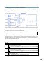
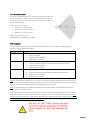
Yacht Sentinel User Guide Revision 6 21.04.2015 1 Contents Input and output connections ........................................................................................................................................ 3 Installing the device ........................................................................................................................................................ 4 Sensors and types………………………………………………………………………………………………………………………………….....…. 4 Bilge sensor…………………………………………………………………..……………………………………………………………….. 4 Hatch sensor…………………………………………………………………………………………………..……………………………… 4 Movement sensor…………………………………………………………………………………..……………………………………… 5 Power…………………………………………………………………………………………………………………………………………………………… 5 Install device………………………………………………………………………………………………………………………………………………….6 Insert SIM………………………………………………………………………………………………………………………………………………………6 Switching the Yacht Sentinel on/off……………………………………………………………………………………………………………….6 SMS ................................................................................................................................................................................ 7 SMS commands……………………………………………………………………………………………………………………………………………..7 Password reset…………………………………………………………………………………………………………………………………………….. 8 SMS message types……………………………………………………………………………………………………………………………………….8 Parameter SMS………………………………………………………………………………………………………………………….…… 8 Status SMS………………………………………………………………………………………………………………………………….….. 9 Alarm SMS……………………………………………………………………………………………………………………………………. 10 Error SMS……………………………………………………………………………………………………………………………………….11 Tracking SMS………………………………………………………………………………………………………………………………… 11 LED flashing codes……………………………………………………………………………………………………………………………………….11 FAQs………………………………………………………………………………………………………………………………………………………………………… 12 Trouble shooting…………………………………………………………………………………………………………………………………………12 Technical specification ……………………………………………………………………………………………………………………………….13 Warranty and disclaimer…………………………………………………………………………………………………………………………….13 Contact details …………………………………………………………………………………………………………………………………………..14 2 Input and output connections To attach the sensors to the base unit please follow the diagram below. Strip 5mm from the end of each cable to expose the wire. Pull the long insert out of the base unit and using an electrical screwdriver loosen the screws on top. Insert each wire into a separate port and tighten the screw to secure. You can put multiple sensors into the same port provided they are the same type of sensor. Put the long insert back into the base unit. To ensure that defined levels are detected at the inputs all the inputs are internally ‘pulled up’ by 33k ohm resistors. The Yacht Sentinel needs to detect if a sensor is connected otherwise it will send a ‘not connected’ alarm. This is done by putting a tamper resistor in each of the sensors, these are: Movement sensor Bilge sensor Hatch sensor 10k ohm 100k ohm 10k ohm If other sensor types are used, such as a pressure mat, the tamper resistor must be placed across the input as n the above diagram, otherwise the sensor will not be recognised. When an output is activated the contact will close to GRD, every output can be assigned an alarm input. Outputs are: output 1 = pin 1; output 2 = [pin 2; common ground = pin 3; temperature sensor = pins 4 & 5. Sensor types: Type NO NC BILGE Description A sensor is used with a clean contact as a ‘normal opened’ switch, the Yacht Sentinel will send an alarm if the contact is closed. Note: the contact must be bypassed by a 10k resistor if the sensor does not have an internal one A sensor is used with a clean contact as a ‘normal closed’ switch, the Yacht Sentinel will send an alarm if the contact is opened. Note: the contact must be bypassed by a 10k resistor if the sensor does not have an internal one A special bilge sensor with an internal bypass resistor of 680k. An alarm SMS will send if the sensor is immersed in water. Note: this sensor type can only be used on alarm inputs 2 and 3. 3 Installing the device Sensors and types The Yacht Sentinel has an external connector that enables the connection of power and sensors, look at the diagram below to see how the connections are arranged when in alarm default mode: Inputs: Outputs: It is easy to add other sensors in place of those shown, such as pressure mats, tilt sensors, lanyards etc to monitor a wide range of possible events. There are three external outputs: one external temperature sensor and two ‘clean contacts’ outputs for switching other devices Note: the device should not be installed in a steel hull or on any steel surface as it blocks GPS signals. Please install the device with the logo facing upwards. Bilge sensors Bilge sensors are connected as shown in the ‘External Input Connection Diagram’. Ensure you make a note of which sensor is place in which part of the bilge, as warnings with use these terms. Please use Velcro or double sided tape to affix the bilge sensors into position. Please make sure that you don’t position the sensors too close to the existing bilge level so that you don’t get false warnings. Any sensor being in contact with the water for 1 minute will cause a bilge alarm to be issues. Hatch sensor Please ensure that the hatch sensor is connected as shown in the ’External Input Connections’ diagram. The hatch sensors consist of one connected component and one free component. The free component has an internal magnet that is detected by the connected component; when the free component moves away from the fixed component an alarm is registered. It is therefore important that with the hatch in a closed position the fixed and free components are side by side. Hatch sensors should be mounted on the hatch door frame. 4 Infra-red movement sensor This sensor is designed to detect any movement by using heat sensing. Any person entering the PIR detection area will be detected as a moving heat source. The sensor turns on detection once every second, has a range of 4 meters at an angle of 90° The connections are as follows: Red wire – screw connector 1 Brown wire – screw connector 2 Black wire – screw connector 3 The command to set the alarm is: 4444,PARAMETER?,ALARM1,on,no,piralarm Power connection The Yacht Sentinel requires a single power supply in the range of 12v to 24v / 600mA. The following gives an overview of average current consumption: Average Current Up to 20mA Up to 25 mA Up to 45mA Modes GSM is registered and on standby GPS is in standby Tracking mode is disabled MOVE alarm is disabled GSM is registered and on standby GPS is on standby and active periodically to update GPS position Tracking mode is disabled MOVE alarm is enabled GSM is registered and on standby GPS is fully powered and constantly updating the GPS position Tracking more is enabled MOVE alarm is enabled Note: the stated current consumption is an average. Due to the internal battery charger the measured current can vary from the values in the table, to find the average it is necessary to measure the consumed current for at least 10 days to ensure that both complete charge and discharge periods are measured. Note: the standby current for the GSM and GPS depends on the GSM-provider, environmental conditions and distance from the providers’ antenna. The Yacht Sentinel comes with a battery supply lead, or with an optional AC mains adaptor power supply lead. Both supply lead connectors use the supply socket shown, all supplies come with the connector already attached, please do not remove the connectors from their leads as the connector is designed to fit only the supply socket. If you wish to use mains supply you must use the power adaptor unit. 5 Insert SIM The Yacht Sentinel is supplied with a SIM card and swipe top-up card, this means that you can put credit on the SIM without needing to remove it from the device. You may change the supplied SIM for one of your own, but we recommend one with low SMS costs. The SIM card is installed by sliding the SIM card into the slot on the top long side of the device. Once the SIM is fully inserted you will feel it connect with a spring, push against this until you hear a ‘click’. The SIM card will now be in the locked position. To remove the SIM press the card in using a pin to disengage the spring lock. Switching on the Yacht Sentinel The Yacht Sentinel is delivered with the internal battery disconnected. Open the unit at the ‘seam’ by gently inserting a flathead screwdriver or knife and twisting until the lid ‘pops’ off. You will see the free battery connector, please plug this into the adjacent socket. To switch on the device briefly press the button. The LED with flash three times to indicate that the unit is switched on. To switch off the device, press and hold the button for three seconds. The LED will flash three times to indicate that the unit is switched off. Note: The internal battery may become fully discharged if the device is switched off for a long period. If you then connect the unit to a power supply, the device enters a charge phase in order to fully charge the battery. During this phase the GSM and GPS are non-operational. The Yacht Sentinel automatically returns to normal operating mode when the battery reaches its charge threshold, typically after 2-3 hours. 6 SMS SMS Commands You can send commands to Yacht Sentinel by sending an SMS to the SIM card phone number or by using the Yacht Sentinel app, available for Android and Apple devices. SMS commands are not case sensitive, but it is necessary to space commands using a comma. Please note that an SMS sent to the unit will only be recognised if the password is at the start of the message. The default password is 4444. SMS command PARAMETER? STATUS? MASTER1= MASTER2= MASTER3= TEMPALARM= TEMPMAX= TEMPMIN= MOVEALARM= RADIUS= BATT= SUPPLYALARM= ALARM1= ALARM2= ALARM3= ALARM4= OUT1= OUT2= OUT1DELAY= OUT2DELAY= NAME= MMSI= Description Request for a parameter SMS. The device will send a parameter SMS to the originator. Request for a status SMS. The device will send a status SMS to the originator. Command to set the phone number for Master1 (max. 18 characters) Command to set the phone number for Master2 (max. 18 characters) Command to set the phone number for Master2 (max. 18 characters) Command to enable or disable the temperature [YES / NO] Command to set the threshold temperature in °c for the temperature alarm [0 – 100] Command to set the threshold temperature in °c for the temperature alarm [-20 – 100] Command to enable or disable the move alarm [YES / NO] Note: The RADIUS parameter gives the permitted movement of the boat around the home position. If the boat moves outside of the set radius, the device send MOVE-OUT to the masters. If the boat moves back within 15m of the home position the Yacht Sentinel sends MOVE-IN to the masters. Command to set the permitted movement in meters if the move alarm is enabled [20 – 200] Note: The Yacht Sentinel works internally within steps of 5m, so the set value will be rounded to the last multiple of 5 Command to set the type of battery to either 12v or 24v. If ‘off’ set the supply type to shore power Command to enable or disable the battery alarm [ON / OFF] Command to set the parameters for the alarm input 1-4. The command has three parameters: [ON / OFF] enables or disables the alarm [NC / NO] the connector sensor set to normally open or normally closed <Alarmtext> to indicate the alarm in the SMS. Parameters can be set like so: ALARM1=ON,NC,ALARMTEXT Command to set the output 1 – 2 [ON / OFF] enables or disables output [0 – 86400] sets how long the alarm is active for (if 0 permanently active) [ALARM1 - ALARM4] enables output when the alarm occurs. Default = OFF Note: ON connects the output direct to ground and OFF makes it high impedance. If the output is an alarm, output is OFF until the alarm occurs Command to delay the output 1-2 [0-86400] seconds sets the length of the delay and duration of the alarm Command to set the name of the boat [max. 12 characters] Command to set Maritime Mobile Service Identity [max. 12 characters] 7 NEWPWD= TRACKING=n,d Command to change the default password [max. 4 digits] Command to activate SMS tracking (e.g. 10,2) N= number of tracking SMS [0 – 20] D= minutes between each SMS [1 – 10] To deactivate TRACKING=0 Password reset The Yacht Sentinel has the default password 4444. Please do the following to change the password: 1. 2. 3. 4. 5. 6. Ensure the Yacht Sentinel is switched on and registered to the GSM network Phone the Yacht Sentinel The LED with start to flash within 30 seconds Push the red button once to end the call The Yacht Sentinel sets the password to 4444 and sends an SMS notification to all masters Reply to the SMS with the command NEWPWD= and your chosen password SMS message types The Yacht Sentinel sends five different types of SMS: 1. 2. 3. 4. 5. Parameter SMS – this contains all the settings for the device. Status SMS – this reports on the status of your vessel. Alarm SMS – sent automatically by the device if an alarm occurs. Error SMS – sent if there is an error at the alarm sensor. Tracking SMS – when enabled, this contains the GPS position and time/date. Parameter SMS The parameter SMS shows you all the settings for the device. Request the SMS using the command PARAMETER? You will receive the reply similar to the example below: YACHT SENTINEL MY BOAT MMSI=680038636 MASTER1=+44179123xxxx MASTER2=NA MASTER3=NA ALARM1=OFF,NO,PIRALARM ALARM2=OFF,BILGE,BILGEALARM ALARM3=OFF,BILGE,BILGEALARM ALARM4=OFF,NC,HATCHALARM OUT2=ALARM1 TEMPALARM=ON TEMPMAX=70 TEMPMIN=-2 SUPPLYALARM=ON BATT=12 MOVEALARM=OFF RADIUS=20 8 SMS text YACHT SENTINEL MY BOAT MMSI=68003836 MASTER1=+44179123xxxx MASTER2=NA MASTER3=NA ALARM1=ON,NO,PIRALARM ALARM2=ON,BILGE,BILGEALARM ALARM3=ON,BILGE,BILGEALARM ALARM4=ON,NO,HATCHALARM OUT2=ALARM1 TEMPALARM=YES TEMPMAX=70 TEMPMIN=-2 SUPPLYALARM=ON BATT=12 MOVEALARM=OFF RADIUS=20 Description Device logo Name of the boat The MMSI number set by the user (default 000000000) Master phone number 1 (and alarm SMS will be sent to this user) Master phone number 2 (and alarm SMS will be sent to this user) Master phone number 2 (and alarm SMS will be sent to this user) Indicates that the PIR alarm is enabled Indicates that the bilge alarm is enabled Indicates that the bilge alarm is enabled Indicates that the hatch alarm is enabled Indicates that output 2 will operate if the PIR alarm is activated Indicates that the temperature alarm is enabled Threshold for the high temperature alarm Threshold for the frost alarm Indicates that the battery alarm is enabled 12v battery type used Indicates that the move alarm is enabled Gives the range in meters for the move range Status SMS The status SMS contains all the actual values, e.g. the GPS position and the voltage of the internal battery. Request the SMS using the command STATUS? you will receive the reply similar to the example below: YACHT SENTINEL MY BOAT MMSI=680038636 FW=20090720 GSM=-89dbm BOATBATT=11.7v VBATT=4.2v TEMP=25 GPSFIX=YES TIME=11.26.35 DATE=31-03-15 LAT=52 06.4445N LONG=008 39.8726E SOG=33 COG=74 SMS text YACHT SENTINEL MY BOAT MMSI=680038636 Description Device logo Name of the boat The MMSI set by the user (default 000000000) 9 FW=20090720 GSM=-89dbm BOATBATT=11.7v VBATT=4.2v TEMP=25 GPSFIX=YES TIME=15.26.35 DATE=31-03-15 LAT=52 06.4445,N LONG=008 39.8726,E SOG=33 COG=74 Firmware version GSM level Voltage of the boat batter / external power supply Note: if BATT is set to OFF the device will write SHOREPOWER=YES/NO in the SMS instead of BOATBATT Voltage of the internal battery Temperature measured in °c ‘YES’ if the device can receive the GPS position, otherwise ‘NO’ Time when GPS was identified Date when GPS was identified Latitude Longitude Speed over ground in knots Course over ground in knots Alarm SMS If an alarm is triggered an alarm SMS will be sent automatically by the device to the numbers Master1, Master2 and Master3. The device will resent the SMS every 30 seconds until it is successful. The alarm SMS will alert you to the source of the alarm then follow with the standard status report. <Alarm source> YACHT SENTINEL MY BOAT MMSI=680038636 BOATBATT=11.6v VBATT=4.2v TEMP=25 GPSFIX=YES TIME=11.26.35 DATE=31-03-15 LAT=52 06.4445N LONG=008 39.8726E SOG=33 COG=74 <Alarm source> -=HITEMP-ALARM=-=FROST-ALARM=-=<CUSTOMER NAME>=- -=SHOREPOWER-ALARM=-=BATT-ALARM=-=MOVE-OUT=-=MOVE-IN=- Description Indicates that a high temperature alarm has occurred Indicates that a frost alarm has occurred For the alarm inputs 1 to 4 a custom name can be assigned. The standard alarm names are: Alarm1=PIRALARM, Alarm2=BILGEALARM1, Alarm3=BILGEALARM2, Alarm4=HATCHALARM Indicates that the shore power has been removed Indicates that the battery voltage is low Indicates that the device has moved out of the set GPS geofence position Indicates that the device has moved into the set GPS geofence position 10 Sensor Temperature sensor Hatch sensor and PIR Bilge sensor Boat battery Shore power Alarm behaviour Alarms immediately. Timeout for the next alarm is 10 minutes Alarms immediately. Timeout for the next hatch alarm/movement sensor is 10 minutes Alarms after 1 minute if one or more sensors are immersed in water Alarms 30 seconds after the voltage of the boat batter is below the set level. Timeout for the next boat batter alarm SMS is 10 minutes after the voltage is above the set level Alarms 30 seconds after the Yacht Sentinel recognises shore power is not connected. Timeout for next shore power alarm is 10 minutes after shore power is recovered Error SMS If there is an error an SMS will be sent automatically by the device to the numbers of Master1, Master2 and Marster3. The device will resent the SMS every 30 seconds until it is successful. -=ERROR=<Error description> YACHT SENTINEL MY BOAT MMSI=680038636 <Error description> SENSOR 1 – 4 NOT CONNECTED SHORT CIRCUIT ON SENSOR 1 – 4 Description Check the connection between the Yacht Sentinel and the sensor on input 1 – 4 Check the contacts on the sensor connected to the shown input. They should be clean and not bypassed Tracking SMS The tracking SMS will be automatically sent by the device if the tracking mode was previously activated. The SMS will send to the person who activated the tracking mode, but not to all masters. The device will resend the SMS every 30 seconds until it is successful. LED flashing codes The Yacht Sentinel uses different flashing codes of the red LED to indicate the current state of the GSM module: LED 1 x flash 2 x flash 3 x flash Fast flashing Slow flashing GSM network The Yacht Sentinel is registered (logged in) and ready to use The Yacht Sentinel is registered (logged in) and ready to use The Yacht Sentinel is not registered in the GSM network The Yacht Sentinel is sending or receiving an SMS The internal battery is in low voltage state and it should be supplemented by the external voltage. The GSM module cannot be used in this state GPS A GPS position is recognised A GPS position is not recognised 11 FAQs Trouble shooting My Yacht Sentinel is not sending alerts Ensure that the Yacht Sentinel is switched on with sufficient power, check the battery connection Check that the SIM card is properly inserted Check that the SIM card has enough credit Stand by the Yacht Sentinel and send an SMS command, check to see that the LED flashes to confirm that it has received the message Test that the SIM card is working properly by inserting into a mobile phone My Yacht Sentinel is not holding its charge See the speed at which the LED flashes and check against the table on the previous page Ensure that the internal battery is properly connected Check the power lead is connected properly, that the battery voltage of the boat is above 12vDC or that you have shore power Switch the Yacht Sentinel off and leave overnight to charge fully I received an ERROR NOT CONNECTED message, how can I check the sensor connection? Check that the wire is securely attached to both the base unit and the sensor Check the length of the wire connecting the sensor to the base unit for breaks Once you have checked everything trigger the alarm (e.g. by placing the bilge sensor in water) and make sure there is a response. My Yacht Sentinel cannot find a GSM or GPS signal Ensure that the SIM card has credit Test the unit in an area where there is good mobile phone reception (e.g. near a phone mast), if it can connect there but not further away consider purchasing an extended antenna. If the above does not work then contact the Yacht Sentinel technical support department For technical support and repairs please email [email protected] 12 Technical Specification General: Casing measures approx. 12 x 7 x 3cm Determination / transmission of GPS coordinates, speed, additional information from inputs Determination / transmission of GSM cell data and provider information (optional) Parameter configuration via SMS Current state is indicated via a red LED Ambient temperature: 0 - +50°c Storage temperature: 10 - +70°c GSM: GPS: Integrated GSM module: Telit GE865 Suitable for all networks, frequencies (GSM850, E-GSM900, DCS1800, PCS1900) and other providers UMTS not supported Usable with a prepaid or contract SIM card from all providers. No SIM lock Controlled via normal SMS. Acknowledgement via received SMS SiRFstarllll receiver with excellent GPS performance 20-channel GPS receiver Internal patch antennae Disclaimer and warranty Please be aware that the use of the Yacht Sentinel is at the users own risk. Please see the website for terms and conditions. All new goods supplied by Yacht Sentinel have a 12 month warranty from the date that the goods were delivered (unless stated otherwise). This warranty does not affect your statutory rights as a consumer. If new goods develop a defect within the warranty period please contact us at [email protected] and we will advise the returns procedure. Please note that the warranty does not cover you for any defect in the goods arising from reasonable wear and tear, willful damage, accident, negligence by you or any third party, use otherwise than in accordance with its intended use, failure to follow the manufacturer’s or supplier’s instructions, or any alteration or repair carried out without the Yacht Sentinel support departments prior written approval. 13 This is a product of Intelligent Devices Ltd Elmbridge House Elmbridge Lane Woking Surrey GU22 9AF Tel: +44 (0)1932 506 173 Email: [email protected] www.yacht-sentinel.com 14