1
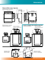
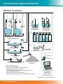
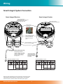
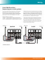
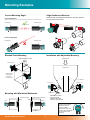
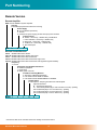
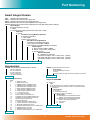
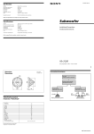
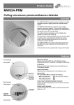
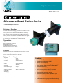
A higher level of performance Data Sheet Microwave Smart Switch Series - Beam blockage detection - Principle of Operation A beam of microwave energy passes from a sender to a separate receiver in bursts approximately 200 times per second. If the path between the sender and receiver is blocked by any object or material which absorbs or reflects microwave energy, then the receiver will not be able to detect the signal. The presence or absence of the signal at the receiver is used to switch a relay for indication or control purposes. Typical Uses Blocked chute detection Stacker/reclaimer protection Shiploader protection Nucleonic switch replacement Hi level alarm / Low level alarm Truck/machine detection Function Detection of objects or material between two points. Can be used for blockage detection, barrier detection, machine detection or protection and point level detection. Primary Areas of Applications - Asphalt - Brewing - Cement - Chemical - Dairy - Edible oil - Fertilizer - Food & Beverage - Glass - Mining & Metals - Oil & Gas - Packaging - Paint - Paper - Pharmaceutical - Plastics - Power Generation - Refining - Semiconductor - Sugar - Textile - Water & Wastewater Features: • • • • • • • • • • • • LCD setup/diagnostics on remote amplifier Ranges up to 200 meters (656 ft) Simple ‘1-minute’ setup Remote sensor or Smart Integral ‘all in one’ types Relay outputs: Smart Integral (1) Remote (2) Remote test function Adjustable ON and OFF delays (0-20 sec) Smart communication options: GosHawk, Modbus, HART, Profibus DP, DeviceNet Remote GSM connection option Remote amplifier to sensor separation up to 500 meters (1640 ft) Bright visual status indication on sensors Independent housing alignment after mounting sensor Typical Applications Machine Protection Coal Fired Power Station, Bulk Material Handling High/Low blocked chute detection For dual receiver wiring see user manual. Gladiator Receivers Boom Protection Sender Gladiator Gladiator “Blocked Chute” Mount Microwave under pulley or out of main system flow Shiploader Protection Microwave Blocked Chute Detection Cement Plants Solid Level - Cyclone Bin High/low Level Receiver High Gladiator Shiploader Luffing Control/Boom Protection Sender Receiver Gladiator Microwave Series Sender Low Gladiator Dimensions Remote Microwave System 30.7 mm (1.2”) 7.5 mm (0.3”) 111.5 mm (4.4”) 78 mm (3.1”) 192.5 mm (7.6”) 147 mm (5.8”) 131.5 mm (5.2”) 190 mm (7.5”) 107 mm (4.2”) 147 mm (5.8”) 158 mm (6.2”) 182.5 mm (7.2”) 50 mm (2”) 74 mm (2.9”) Remote Sender / Receiver Standard Sender/Receiver 4 mm (0.2”) Smart Integral Microwave System High Power Sender, Receiver or SRS Receiver Standard Sender/Receiver High Power Sender, Receiver or SRS Receiver Ø85 mm (3.3”) Ø88 mm (3.5”) Ø160 mm (6.3”) Ø88 mm (3.5”) Ø160 mm (6.3”) Ø165 mm (6.5”) Ø165 mm (6.5”) Ø277 mm (10.9”) Ø277 mm (10.9”) Ø22x8 mm Holes THRU 160 mm (6.3”) 135 mm (5.3”) 8 Ø23 Alignment marks 160 mm (6.3”) Standard Sender/ Receiver Flange 250 mm (9.8”) 2 mm (0.078”) 129.5 mm (5.1”) 135.5 mm (5.3”) 129.5 mm (5.1”) 135.5 mm (5.3”) 250 mm (9.8”) 90 mm (3.5”) 50 mm (2”) Ø85 mm (3.3”) 2 mm (0.078”) 50 mm (2”) 10 mm (0.4”) 12 mm (0.5”) 90 mm (3.5”) 50 mm (2”) 10 mm (0.4”) 90 mm (3.5”) 50 mm (2”) Ø85 mm (3.3”) Ø85 mm (3.3”) 12 mm (0.5”) 108 mm (4.3”) 190 mm (7.5”) 182.5 mm (7.2”) 167.5 mm (6.6”) 141.5 mm (5.6”) 14 mm (0.6”) 192.5 mm (7.6”) 174 mm (6.9”) 90 mm (3.5”) Remote Amplifier Enclosure ”) (9.3 mm High Power Sender/ Receiver or SRS Flange 4x10 mm holes Ø165 mm (6.3”) Ø277 mm (10.9”) Ø88.5 mm (3.5”) Gladiator Microwave Series Communication Network Overview Multidrop Connections Gladiator Admittance Switch Gladiator Admittance Switch Gladiator Admittance Switch Gladiator Admittance Switch Sultan Acoustic Wave Transmitter Slurries GLadiator Microwave Low Level Gladiator Microwave Low Level Sultan Acoustic Wave Transmitter Floatation Cells Gladiator Vibration Switch Sultan Acoustic Wave Transmitter Silo, bin levels, coal, plastic powder, woodchip, sawdust, cement, clinker, iron ore, lime etc. SULTAN 234 Gladiator Conductivity Switch Sultan Smart Transducer Farm Tanks, Grain Terminals Orca Sonar Interface Gladiator Conductivity Switch SULTAN 234 Thickener, CCD Sultan Acoustic Wave Switch Blocked Chute Detection Orca Sonar Interface Clarifier Sultan Master/Slave Positioning System GSM Network or CDMA Network Sultan Acoustic Wave Transmitter Stockpiles, Stackers, Reclaimers GSM or CDMA Network • Typically up to 31 transmitters or switches per string. • Maximum 250 transmitters or switches. • Using GSM/CDMA network, transmitters and switches can be • • monitored, calibrated remotely. Alarm status, diagnostics can be monitored. Support from factory engineering for customer application problems. Laptop or PC Communications or PLC / DCS with MODBUS RTU Port GosHawk Software for inventory monitoring on PC (Limited Modbus query rate for Switches only) Gladiator Microwave Series Wiring Remote System Connection Remote Receiver Remote Sender Terminals 1, 2, 3, 9, 10 not used 9. INT 1 10. 8. BLACK 7. RED 5. 6. 3. 4. BROWN 2. 1. 9. 10. 8. BLACK 7. RED 5. WHITE 6. BLUE 3. 4. BROWN 2. 1. Green Power ON LED Red Transmitter enabled LED TERMINAL LAYOUT TERMINAL LAYOUT 2 MICROWAVE SENDER 3 PRESS TO TEST PWR TX Terminals 1, 2, 3, 5, 6, 9, 10 not used 1 Green Power/ Signal strength/ alignment indicator LED Signal 2 3 4 5 6 3 4 5 6 7 8 9 10 Remove Plug-In terminal block for easier wiring. Status 1 2 7 8 9 10 Signal strength/ alignment test point for volt meter connection Hole for securing of optional identification tag M4 grounding screw ** NO COM NO RELAY 2 NC COM NC Test in SLAVE IN RELAY 1 BROWN AC-IN – + 24 VDC L1 DC-IN N A WHITE BROWN BLUE COMMS B BLACK BLACK + – SENSOR RED CURRENT Is **Ground the housing to vessel, if vessel is metallic. Ground the housing to plant ground, if vessel is non-metallic. RED + – Tx MIC-SENDER MASTER OUT GLADIATOR MICROWAVE REMOTE AMPLIFIER 80-265 VAC Relay 1 - Output Relay Relay 2 - FailSafe Relay Alternate cable type between Amplifier and Sensors 6 or 8 conductor (5 used) shielded twisted pair instrument cable. Conductor size dependent on cable length. BELDEN 3120A, DEKORON or equivalent. Max: BELDEN 3120A = 500m (1640 ft). 3 pairs, 1 conductor not used. Max: DEKORON IED183AA004 = 350m (1150 ft). 4 pairs, 3 conductors not used. Note: AC power terminals may only be used when universal AC power supply option has been selected - see part numbers - AC terminals have no function in products without universal AC power option. Alternate Cable Colour Equivalents Hawk Belden 3120A Dekoron Pair 1 Red Black Red Black White 1 Black 1 Pair 2 White Blue Yellow Green White 2 Black 2 Pair 3 Brown --- Brown White (not used) White 3 Black 3 (not used) Pair 4 - not used Gladiator Microwave Series Wiring Smart Integral System Connection Smart Integral Receiver Smart Integral Sender Y HI FSH CAL EN S 1 2 3 4 5 6 7 8 Green Power ON LED Red Transmitter enabled LED Remove Plug-In terminal block for easier wiring. TEST DELAY SITIVIT Green Power/Signal strength/alignment indicator LED Blue Calibration/Error LED Red Relay Status LED INT 1 9 10 1 2 2 3 MICROWAVE SENDER 3 PRESS TO TEST PWR TX 4 5 6 7 8 9 10 The AC earth/ground cable must be connected to the ground screw inside the housing when using AC power. Hole for securing of optional identification tag M4 grounding screw If only one cable is used for both power and output signal, then the second entry port must be plugged or blinded. Every Smart receiver is supplied with two M20 glands (or 3/4”NPT adaptors) mounted on the unit and one blind plug loose. N L1 8. 9. 10. 6. 5. 10. 4. L1 9. 3. N 8. - 12-30VDC 80-265VAC 12-30VDC 80-265VAC Terminals 1, 2, 3, 4, 5, 6 not used Note: AC power terminals may only be used when universal AC power supply option has been selected - see part numbers - AC terminals have no function in products without universal AC power option. Gladiator Microwave Series 2. - AC-IN 7. DC-IN 1. B 6. RS 485 SENDER TERMINAL LAYOUT AC-IN 7. A 5. 4. Test NO 3. 1. 2. COM RECEIVER TERMINAL LAYOUT COMMS DC-IN RELAY NC ** **Ground the housing to vessel, if vessel is metallic. Ground the housing to plant ground, if vessel is non-metallic. Wiring Cross-Talk Prevention Sequencing two remote systems To prevent possible interference between two remote beam blockage detection systems mounted in close proximity, one system must be selected as a ‘Master’ and the other as a ‘Slave’. The Operation Mode selection can be found in the advanced menu of the remote amplifier for each system. Additional wiring must be installed between the two amplifiers as shown below. A connection must be made between the ‘Master Out’ terminal of the amplifier selected to operate as the Master and ‘Slave In’ terminal of the unit selected to operate as the Slave. The cable shield and/or a second connection must link the DC-IN ‘-’ terminals of the two units. Operation Mode has 3 selections: 1. Remote - normal unsequenced (single system) operation 2. Master - controlling system in a sequenced group of two units 3. Slave - controlled system in a sequenced group of two units Receiver 2 Sender 1 – + 24 VDC NO COM AC-IN L1 DC-IN N NO RELAY 2 NC COM Test in MASTER OUT Tx SLAVE IN NC A B + – RELAY 1 COMMS BROWN Is 80-265 VAC SENSOR BLUE COM NO CURRENT WHITE 24 VDC + – L1 – + MIC-SENDER AC-IN N NO DC-IN GLADIATOR MICROWAVE REMOTE AMPLIFIER - SLAVE RELAY 2 NC NC A COM Test in MASTER OUT COMMS BROWN BLUE WHITE RED + – SENSOR BLACK Is CURRENT RELAY 1 B + – Tx MIC-SENDER SLAVE IN GLADIATOR MICROWAVE REMOTE AMPLIFIER - MASTER Sender 2 SLAVE* RED MASTER* BLACK Receiver 1 - Smart integral systems are not intended to be sequenced. - If systems are to be installed in close proximity to one another, remote types should be used to allow sequencing. - Sequencing of more than 2 systems near one another must be done using a GMSEQ sequencing unit connected to all systems as described in the manual. 80-265 VAC Ground Ground * Software selected Gladiator Microwave Series Mounting Examples Correct Mounting Angle Align Sender and Receiver Rotate so that Visual Alignment Guide is in the same position on both sender and receiver. Correct Elevation Maximum Signal Strength to Receiver is indicated by maximum brightness of Green LED on Receiver. Sending Unit Receiving Unit Microwave Beam Incorrect Elevation Sending Unit Receiving Unit Blocked Chute Mounting Installation with Adjustable Mounting Product Flow MAIN PRODUCT FLOW Receiving Unit Hooper/Feeder Sending Unit Position blocked chute detectors to one side of main product flow X X Receiving Unit Sending Unit Mounting with Windowed Weldments Isolation Mount Flow/No Flow MAIN PRODUCT 4” UHMW Windowed Weldments Metal Bin/Chute Walls FLOW Sender Receiver Gladiator Microwave Position and aim Series flow sensors Adjustable microwave mounting bracket welded to vessel wall. UHMW or Teflon Window. Housing can be rotated within 200º after the mounting thread is tightened, to allow cable entries to face downwards or allow optimal cable clearance. Fabricated Brackets X = 30° Maximum Communication Network Overview GSM/CDMA Communication HawkLink GSM/CDMA communication device allows any authorized computer with a standard modem and GosHawk software to dial in and calibrate, test or check on the performance of the connected Hawk product. The HawkLink device can be wired to the standard communication terminals of the Hawk products. Remote technical support and complete commissioning of equipment in applications via our GSM/CDMA module allows monitoring and adjustments of settings no matter what corner of the world. Remote connection worldwide! Gladiator Microwave Series Part Numbering Remote Version Remote Amplifier GSA Remote Gladiator System Amplifier Housing S Standard polycarbonate electronics housing Power Supply B 24 Vdc standard (12-30Vdc) C 48 VDC U Universal AC power supply (90-260 VAC input) and 12-30Vdc Output Options S Switch. 1 level relay, 1 failsafe relay, with Modbus I HART Isolated. 1 level relay, 1 failsafe relay D Devicenet. 1 level relay, 1 failsafe relay P Profibus DP. 1 level relay, 1 failsafe relay Z Special Request GSA S B S Remote Sender/Receiver GMSB Gladiator Microwave Sender GMSHB Gladiator Microwave Sender High Power GMRR Gladiator Microwave Remote Receiver GMRRH Gladiator Microwave Remote Receiver High Power GMRRS Gladiator Microwave Remote Receiver with Signal Recognition Stability Frequency 1 10 GHz Transducer Facing Material Selection 0 UHMW Polyethylene 1 PTFE Teflon W Wave guide connector Transducer Housing Material 1 Aluminium / Mild Steel (Standard) 2 Full stainless steel GMSB or GMRR 3 Full stainless steel GMSHB/GMRRH or GMRRS Output Option X Not required - Outputs generated from GSA amplifier Approval Standard X Standard CE approved A1 ATEX Encapsulated (Grp II Cat 2 GD Eex m II IP68) *pending A20 ATEX Dust (Grp II Cat 1 D T85C IP67) *pending A21 ATEX Dust (Grp II Cat 2 D T85C IP67) *pending A22 ATEX Dust (Grp II Cat 3 D T85C IP67) *pending GMSB 1 0 1 X X * Connection cable is not included. Please see cabling Accessories section Gladiator Microwave Series 10 Part Numbering Smart Integral Version GMS Gladiator Microwave Sender GMSH Gladiator Microwave Sender High Power GMSR Gladiator Microwave Smart (Integral) Receiver GMSRHGladiator Microwave Smart (Integral) Receiver High Power GMSRSGladiator Microwave Smart (Integral) Receiver with Signal Recognition Stability Power Supply B 24Vdc standard (7-30 Vdc) C 48Vdc U Universal power supply (80-260 VAC input) and 7-30Vdc Frequency 1 10 GHz Transducer Facing Material Selection 0 UHMW Polyethylene 1 PTFE Teflon W Wave guide connector Transducer Housing Material 1 Aluminium / Mild Steel (Standard) 2 Full stainless steel GMS or GMSR 3 Full stainless steel GMSH/GMSRH or GMSRS Output Option X Not required for GMS or GMSH S Switch, 1 output relay, with Modbus Z Special request Approval Standard X Standard CE approved A20 ATEX Dust (Grp II Cat 1 D T85C IP67) *pending A21 ATEX Dust (Grp II Cat 2 D T85C IP67) *pending A22 ATEX Dust (Grp II Cat 3 D T85C IP67) *pending GMSR B 1 0 1 S X Accessories GMSEQ Gladiator Microwave Sequencer Power Supply B 24Vdc standard (12-30 Vdc) C 48Vdc U Universal power supply (90-260 VAC input) and 12-30Vdc GMSEQ U CA-GMR Pre-cut cable for remote sender or receiver 10 10m cable each 20 20m cable each 30 30m cable each 50 50m cable each 100 100m cable each CA-GMR10 MA Mounting Accessory HawkLink GSM/CDMA HL Hawk Link Type E Circuit Board only for installing in to Remote c/w antenna (2). R Remote stand alone system mounted in a Remote Enclosure c/w antenna. Power Supply B 24 VDC U Universal 90-260VAC X No power supply for E Selection Network Type G2 GSM Frequency 850/1900 MHz/19200 Baud for USA,Canada,Argentina,Chile G4 GSM Frequency 900/1800 MHz/19200 Baud for Australia,Europe,Brazil P Phone Line E Ethernet HL R U G4 Type 03” Weldment, each 1 2” Glass window each 33” UHMW Windows & Weldment each 4 4” UHMW Windows & Weldment each 5 6” UHMW Windows & Weldment each 63” PTFE Windows & Weldment each 7 4” PTFE Windows & Weldment each 8 6” PTFE Windows & Weldment each 99’ x 4,5” Fire brick each 10 6” x 4” ceramic brick each 11 Shock insulation mounts pack of 4 12 Adjustable mounting UHMW windows each 13 Adjustable mounting PTFE windows each 14 Remote wave guide Assembly 15 Mounting Flange pipe 163” Ceramic window & weldment each 17 4” Ceramic window & 4” weldment each 18 4” Microwave Weldment only each 193” Stainless steel Weldment only for UHMW each 20 4” UHMW Windows only each 213” UHMW Windows only each 22 4” Stainless steel Weldment only for UHMW each MA 0 11 Gladiator Microwave Series Specifications Operating Voltage • Smart 7-30Vdc/Remote 12-30Vdc (residual ripple no greater than 100mV) • Smart 80-260Vac/Remote 90-260Vac 50/60Hz Sender/Receiver to Amplifier Separation • Up to 500m (1640ft) using specified extension cable Alternate cable type between Amplifier and Sensors • 6 or 8 conductor (5 used) shielded twisted pair instrument cable. Conductor size dependent on cable length. BELDEN 3120A, DEKORON or equivalent. Max: BELDEN 3120A = 500m (1640 ft). 3 pairs, 1 conductor not used. Max: DEKORON IED183AA004 = 350m (1150 ft). 4 pairs, 3 conductors not used. Power Consumption • <0.8W @ 24Vdc • <5VA @ 240Vac • <3VA @ 115Vac Communications • GosHawk, Modbus • Remote version also with HART, Profibus DP and DeviceNet (options) • Multidrop mode can address 1-250 units over 4 wires Maximum Operating Pressure • 2 BAR Relay Output: (1) SMART (2) Remote • Form ‘C’ (SPDT) contacts, rated 5A at 240Vac resistive • Remote fail-safe test facility for one relay. Display (Remote version only) • 2 line x 12 character alphanumeric LCD • Backlight standard Memory - Remote • Non-Volatile (No backup battery required) • >10 years data retention Operating Temperature • Remote electronics -40°C (-40°F) to 80°C (176°F) • Smart Units -30°C (-20°F) to 65°C (150°F)* • Remote Sensors -30°C (-20°F) to 65°C (150°F)* *For higher temperature applications, remote mounting with refractory windows is necessary Power Density • Rated from emitter to receiver at approximately 20µW/cm² • Complies with FCC Title Rules Part 15 (Beam Blockage) • Caution sign posting not required Cable Entries Remote Sensors • 1 x M20 Gland/3/4” NPTF threaded adaptor Remote Amplifier • 4 x 20mm (0.8”), 1 x 16mm (0.6”) knock outs. Smart Integral Units • 2 x M20 Glands/ 3/4” NPTF threaded adaptors Transmitted Signal • Frequency: 10.525GHz • Average Power Density: 20µW/cm² typical • Linearly Polarised Field • Beam angle (3db) approximately 30º (10GHz) Mounting • 3” male NPT thread or four 10mm (0.4”) holes in flange on standard units or 6” ANSI flange on high power/SRS units • 3” weldments for standard mounting on vessel wall • Flange for mounting separate from vessel wall - isolation shock mounts are available • 4” or 6” Weldments with PTFE (teflon) or UHMW windows • Ceramic window assemblies • Firebrick window assemblies available on custom basis • 2” NPT sight glass window • Waveguides - custom assemblies available for high temperature and limited access applications Fail-Safe • Selectable - presence or absence of material • High level fail-safe: relay is activated when material is present. • Low level fail-safe: relay is activated when no material is present. Range • Maximum range under ideal conditions: 200m (656ft) • Minimum range under ideal conditions: 10cm (4 inches) Note: Minimum ranges are dependent on application conductivity Additional product warranty and application guarantees upon request. Remote Test Input Press to test (used to check for malfunction of unit from remote position, PLC, SCADA etc) Technical data subject to change without notice. Contact Hawk Measurement Systems (Head Office) 15-17 Maurice Court Nunawading VIC 3131 Australia Phone: +61 3 9873 4750 Fax: +61 3 9873 4538 [email protected] Represented by: Hawk Measurement 7 River Street Middleton, MA 01949 USA Phone: +1 888 HAWKLEVEL (1-888-429-5538) Phone: +1 978 304 3000 Fax: +1 978 304 1462 [email protected] Gladiator Microwave Series 12 For more information and global representatives: www.hawkmeasure.com Rev 1.1, December 2008 All company or product names are registered trademarks or trademarks of their respective owners. Enclosure Sealing • Smart Sensors IP67 • Remote Electronics IP65 (Nema 4x) • Remote Sensors IP67