1
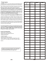
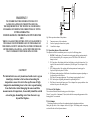
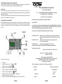
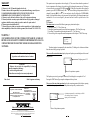
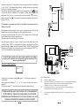
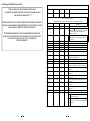
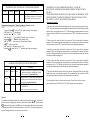
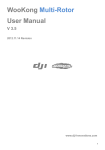
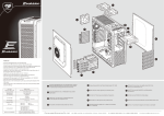
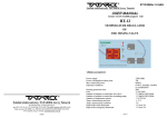
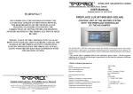
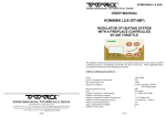
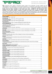
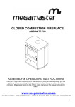
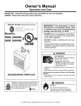
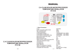
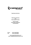
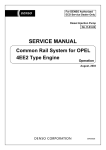
RT08OM/2012/v.1.0/ANG Zakład elektroniczny TATAREK Jerzy Tatarek USER MANUAL v.1.0 (21.02.2011 software 1v0) FIREPLACE OM/FIREPLACE POWER OPTIMIZER RT-08OM 1.Basic technical parameters Power 230V/50Hz Auxiliary power Rechargeable battery 4,8V/60mAh Power consumption without load 5W Max connection power 250W Operation conditions 0-40 oC, humidity 10-90% no condensation Housing protection class IP41 Fuse 6,3A/250V Number of nonvoltage control outputs 1 * contact NO and NC (normally closed and open contact) Zakład elektroniczny TATAREK Jerzy Tatarek 50-559 Wroclaw, 75 Swieradowska st. ph. (071) 367-21-67, 373-14-88, fax 373-14-58; Tax index number 899-020-21-48; Bank account: BZ WBK S.A. WROCLAW 6910901522-0000-0000-5201-9335 www.tatarek.com.pl.; E-mail: [email protected] 16 Number of outputs to control the air damper drive 1 * 5V/500mA/DC 1 * Thermocouple type K (0...+1300 oC ) Number of temperature sensors Temperature measurement precision 5 oC Temperature measurement resolution 1 oC 1 2. Principle of operation The RT-08OM control unit is used to control the combustion process and maintaining the embers phase as long as possible by controlling the air damper that channels air to the combustion chamber. Thanks to lowering the combustion curve during the phase of temperature increase and its raising during the phase of temperature decrease the control unit extends the combustion process. The most important advantage of this model of the optimizer is the capability to choose one of 3 programs for operation power of the input depending on the user's needs and maintaining as long as possible the chosen range of the operation. Thanks to that it's possible to achieve out of a given portion of fuel an optimal portion of energy, which allows to raise functionality economy of the fireplace or stove, to which the RT-08om control unit has been applied. The operation of the RT-08om optimizer control unit begins at the moment that the furnace door closes (the sensor of opening the door D1) or in case of no sensor with the START button on the front control panel. The combustion process starts controlled by the furnace gas temperature sensor that manages the air damper which supplies air to the furnace. At the time of a systematic decrease of temperature (burning out the input) the air damper is being closed. When the embers phase in the furnace is reached the air supply is cut off, interrupted by scavenges in order to get rid of waste gas from the combustion chamber. In alarm situations (also power declines) the air damper is opened that enables the full burnout of the fuel input. The special input to cooperate with an external CO detection sensor improves the safety of using the fireplace. Admission date Realization date Signature The control unit is equipped with its own emergency power supply. The pause in power supply up to 8secs doesn't affect the control unit operation because during that time the buffer power supply switches on (e.g. A200WAC TATAREK). If the pause is longer the air damper opens up in emergency before the optimizer control unit switches off. Advantages of the combustion optimizer: -limiting the maximum combustion temperature -capability of choosing optimal fireplace power for the user -extending the combustion process -decreasing fuel consumption -extending the exploitation time of fireplace inputs -shutting off air supply after ending the combustion (preventing the furnace cool-off) -cooperation with CO sensors (opening up the fresh airing of the combustion chamber in emergency) The optimizer can control a fireplace without the sensor of opening the door. In that case the button START found on the front panel is used. 2 15 Remarks CHIMNEY WARNING!!! WE INFORM THAT THE OFFERED CONTROL UNIT CAN BE ONLY APPLIED TO THE FITTING DEVICES. THE REQUIREMENTS OF THE TECHNICAL AND BUILDING STANDARDS CONCERNING THE CORRECTNESS OF STOVE- FITTER AND HEATING SYSTEMS HANDLING THE FIREPLACE INPUTS MUST BE MET. WRONG USAGE OF THE CONTROL UNIT CAN LEAD BOTH TO ITS DAMAGE AND IN EXTREME CASES TO THE DAMAGE OF THE FIREPLACE INPUT AND HEATING SYSTEM CONTROLLED BY THE FIREPLACE AS WELL , ALONG WITH THE DEVICES THAT COOPERATE WITH THE HEATING SYSTEM. CAUTION ! We inform that in case of systems based on the water cap you should pay attention to the location of mounting the temperature sensor of water in the cap. Because of high temperature maintaining close to the water cap and coming from that both a risk of damaging the sensor and false measurements of temperature, its assembly should be carried out on the pipe channelling water from the water cap beyond the fireplace. FIREPALCE Fig.1 Basic operation scheme of the optimizer T1 D1 PP Temperature sensor of the combustion Sensor of opening the furnace door (option) Controlled air damper 2.1 Operation phases of the control unit The optimizer controls the combustion process as a cycle of the following phases: 1. F0/STOP - Standby phase. The control unit awaits opening the door and preparing the fuel for the next heating. F0 is a temporary state to STOP. In the STOP state the air damper is closed. 2. F1 - Start phase. After loading the fuel and its lighting you close the furnace door. It's a signal for the control unit that the combustion cycle has begun. The air damper is fully open. 3. F2 - Heating-up phase. After reaching the limit temperature and warming up the fireplace the pass to the phase F3 follows. 4. F3- Burning/combustion phase. Stabilization of combustion temperature depending on the chosen power of the fireplace F4 - Phase of decreasing temperature. The air damper is again gradually closed 5. F5 - Embers phase. Signalling the demand for replenishing the fuel 6. F6 - Phase of removing the furnace gases. The air damper first opens up and then closes and there's the pass to the standby phase. 2.2 Power of the fireplace The user himself decides about the heating power of the fireplace. There're 3 power levels: 1(minimum)/2/3(max) with which the corresponding parameters of the burning phase F3 are connected. 2.3 Air damper The air damper regulates air inflow to the combustion chamber dependent on the phase. During the flap move of the air damper the diode (9) lights. The blinking means a temporary overload of the drive affected by met resistances. 14 3 2.4 Additional functions of the control unit The main function of the RT-08om control unit is optimizing the combustion process via the control of air inflow into the combustion chamber realized through the air damper. Additionally: !An external device controlling CO concentration can be connected to the control unit. In case of detecting the danger the air damper (PP) opens up improving the ventilation of room, additionally the signal alarm switches on. ! The control unit switches on the ALARM output in case of damage of the temperature sensor of the furnace (T1) or exceeding of CO concentration. CE CONFORMITY DECLARATION Ref. No. 58.RT.01.2007/1/B We, ZAKŁAD ELEKTRONICZNY TATAREK Jerzy Tatarek 75 Swieradowska St. , 50-559 Wroclaw declare under our sole responsibility that 3.Operating the control unit the following control unit: FIREPLACE POWER OPTIMIZER On the control panel (Fig.2) are the control elements of the control unit. In the standby state the green control diode (7) of the standby state lights. Turning on the control unit occurs after opening the furnace door. The closing of the door starts the combustion cycle, which is indicated by the green diode (8). model: RT-08OM "CHOOSE" is in conformity with the basic requirements included in Directive EMC 2004/108/WE of 15.12.2004 (the electromagnetic compatibility law of 13.04.07) and Directive LVD 2006/95/WE of 21.08.07 (Laws Journal of 2007 No. 155 pos. 1098) regarding the requirements for electric devices. To the conformity evaluation the following harmonized standards were used: PN-EN 60730-2-1: 2002 PN-EN 60730-1: 2002 - Automatic electric control units for house usage and the like. Part 2-1: Specific requirements regarding electric control units for electric house devices Automatic electric control units for house usage and the like. Part 1: General requirements. PN-EN 55022: 2000 Electromagnetic compatibility (EMC)- IT devices Characteristics of radioelectric noises. Acceptable levels and measurement methods Complementary information: Laboratory IASE 51-618 Wroclaw, 1 Wystawowa st. "CONFIRM" Test report No. Fig.2 View of control panel 1. Text display 2. Button to increase the value”▲” (or START) 3. Button to choose the parameter „ „ 4. Button to lower the value „” (or STOP) 5. Button to confirm the changes „OK„ (or AUTO) 6. Button to enable the manual mode „ ” (MAN) 7. Status diode of the control unit: alarm (red), standby (green) 8. Diode of the combustion cycle (green) 9. Diode of the air damper operation (blinking means the overload of the drive 4 39/DL/I/07 of 22.06.2007 41/DL/I/07 of 03.07.2007 Electronic Engineering Plant TATAREK has initiated management system and complies with the following standard : ISO9001: 2000 CERTIFICATE No. 133/2004 of 01.2004 Polish Foreign Trade Chamber The last two digits of the year in which the CE marking was affixed: 07 Place of issue: Manufacturer representative: Wroclaw Mirosław Zasępa Date of issue: Position: 08.2007 Konstruktor 13 WARRANTY 1.Warranty is valid [24] months from the date of sale. 2.Producer does not take responsibility for any mechanical damages made by user. 3.MAKING REPAIRS OR MODYFYING THE DEVICE BY USER IS FORBIDDEN AND CAUSES WARRANTY CANCELATION 4.Warranty card is valid only with date of sale, seller's signature and stamp 5.Warranty and after-warranty repairs should be done only by producer, damaged regulators should be sent to producer in order to make all repairs needed. 6.Warranty protection includes the EU 7.Warranty does not exclude, not restrict and not suspend buyer’s rights coming from the incompatibility of the article with the agreement (Laws Journal No. 141 Pos. 1176) WARNING ! ANY MODIFICATION OF THE CONTROL UNIT MADE BY A USER CAN BE THE CAUSE OF SAFETY CONDITIONS DETERIORATION AND CAN EXPOSE THE USER TO ELECTRIC SHOCK OR DAMAGE DEVICES SUPPLIED. Connection cable of the control may be replaced only by producer or his authorized service locations The operation state is presented on the text display (1). The screens inform about the operation of devices, temperature of the furnace; they make it possible to change the parameters etc..The change of screen is done by pressing the CHOOSE button (3). If this is the screen that is able to change a parameter, press the CONFIRM button(5) OK, which causes blinking of the parameter field to be changed. By pressing “ ” (2) or “ ” (4) one can alter its value. By clicking the CONFIRM (OK) button (5) one confirms the changes - the parameter field stops blinking. The changed parameter not confirmed for 10 secs is not accepted by the control unit and it recalls a previous value of the parameter. 3.1 Screens The alarm screen is not seen till the following emergency situation takes place: 1. Damage of sensor T1. “T.Firep” shows up. 2. Damage of internal temperature sensor of reference temperature - "Ref.Temp" shows up. 3. Exceeding CO concentration by shorting the terminal X1 - "Gas" shows up. 4. The exceeding of the acceptable maximum temperature of the fireplace. "T MAX" shows up. ALARM !! TFirep The alarm situation is accompanied by the status diode (7) blinking and a broken sound alarm that can be turned off by pressing any button The screen of the control unit status displays the preset fireplace power and the phase of the control unit operation . 2 F1 WARNING! 1. Producer does not take the responsibility for damage caused by atmospheric discharge 2. and overvoltage in the mains 3. Burnt fuses are not subject to warranty replacement Date of sale Seller's signature and stamp Fireplace power 1/2/3 Phase of the optimizer operation The fireplace power is set by pressing the button (4). On the display it corresponds to 1/2 or 3. Pressing the START button (2) opens up the air damper and the cycle start. The screen of the control unit operation displays the current temperature of the fireplace, opening level of the air damper, phase of the control unit operation and possibly a combustion error ARGO-FILM Recycling Plant No. 6 180 Krakowska st., 52-015 Wroclaw Worn out electronic and electric devices must be transfered to ph.: 071 794 43 01, 0 515 122 142 the utilization collection place, where will be accepted for free Register No.. GIOS: E 0002240WZ Zakład elektroniczny TATAREK Jerzy Tatarek 50-559 Wroclaw, 75 Swieradowska st ph. (071) 367-21-67, 373-14-88, fax 373-14-58; tax index number 899-020-21-48; Bank account : BZ WBK S.A. O/WROCŁAW 6910901522-0000-0000-5201-9335 www.tatarek.com.pl.; E-mail: [email protected] 12 F1 1200 50% Combustion temperature(T1)/ or the blinking text "END" (The refuelling of the fuel is required) Opening level of the air damper Phase of the optimizer operation 5 CHIMNEY Reaching the embers phase F7 is accompanied by a broken sound signal (switch-off with the button (6) ), text “FuelOUT” and blinking of the green diode (8), which indicates the need for replenishing the fuel in case of continuing the burning. Thecontrol unit can run in the automatic or manual mode. The longer pressing “MAN” (6) about 2secs causes the pass to the manual mode. That's signalled by blinking status diode (7). The air damper opens 100%. From now on you can manually control the air damper: “ “(4) causes the shutting (one step-10%) and “”(2) the opening. The comeback to the automatic mode occurs after pressing “AUTO” (5). FIREPLACE ! The transition to the manual mode (MAN) can be blocked if the parameter of level 3 "Manual" is set to WYŁ. In the automatic mode each opening of the door causes the air damper to be set at 100% and each shutting of the door causes the combustion process started and the diode (8) lights. If the furnace is cold then after the time “DelayTim+Ti.STOP” (see parameters of level 2) the control unit closes the air damper and passes to the standby state. Likewise the control unit acts when the power is switched on. During the operation without the sensor of opening the door the panel buttons are used for controlling. Pressing “START” (2) causes opening the air damper and starting the cycle. Before opening the door the air damper should also be opened by pressing “START”(2) or passing to the MAN mode. After lighting the fuel and closing the door you must again press “START” (2) or “AUTO”(5) if the control unit is in the manual mode “MAN”. Air damper RED YELLOW(BLUE) BLACK Door sensor ! In the MAN mode you must not close the air damper completely before reaching the embers phase because there can be a dangerously increased concentration of CO (poisonous carbon monoxide)!!! ! ! FUSE The screen of setting the parameters WHITE GREEN Menu MAINS 0 Normally the level of parameter setting (Menu) equals to “0”, which means the parameters aren’t available. After changing the level (Menu) to “1”, “2” , or "3" the successive screens show the values of parameters. The last screen contains “****” after which it comes back to the above mentioned screens. !!! THEPARAMETERS ADAPT THE CONTROL UNIT TO THE PROPERTIES OF THE FIREPLACE. THEIR CHANGE SHOULD BE CONSULTED WITH THE PRODUCER OF THE FIREPLACE. INCAUTIOUS CHANGES CAN CAUSE UNSTABLE AND INEFFICIENT OPERATION OF THE SYSTEM. !!! 6 Fig.3A Wiring scheme PP X3 D1 T1 Electronically controlled air damper Input to connect a control device of CO concentration. The input “+” has higher potential (it's important for Open Collector Systems). Schort-circuit of the contacts means the exceeding of permitted CO concentration. At the lack of CO control you leave the contacts not connected. sensor of opening the furnace door. At the closed door the terminal D1 should be opened(see Fig.) At the opened door the terminal D1 should be short-circuited. Sensor of combustion temperature. Thermocouple type K (the wire of higher potential is green, of lower one is white) 11 4.Mounting the RT-08om control unit ! THE CONTROL UNIT IS SUPPLIED WITH 230V/50HZ . ANY MOVES REGARDING THE INSTALLATION SHOULD BE MADE AT THE DISCONNECTED MAINS.! ! ! PARAMETRS OF LEVEL 1 NAME RANGE Signal OFF/ON DEFAULT SETTING ON FUNCTION Switch-on/Switch-off of the sound alarms PARAMETERS OF LEVEL 2 ! THE CONTROL UNIT HAS TO BE CONNECTED TO THE MAINS WITH THE ZERO-PIN CABLE THROUGH THE DIFFERENTIAL. DEVICE THAT CUTS OFF THE POWER ACCORDING TO THE REGULATIONS !!! THE PARAMETERS CAN BE ALTERED AT THE UNLOCKED PASSWORD NAME RANGE DelayTim 15…600secs 10…1250 oC 60secs 45 oC Ti.STOP 0…600secs 120secs T.F2 T.F3/1 T.F3/2 T.F3/3 dT.F3 dT.F3-F4 50…1250 oC 50…1250 oC 50…1250 oC 50…1250 oC 10…200 oC -10…-300 oC 400 oC 250 oC 300 oC 350 oC 50 oC -30 oC End temperature of the heating-up phase Temperature of the phase F3 at power=1 Temperature of the phase F3 at power=2 Temperature of the phase F3 at power=3 Maximum temperature increase in the phase F3 Ti.F4 1…10 mins 2 mins T.F5 Ti.F5 Ti.PDM 50…1250 oC 1…60 mins 0…10 mins 150 oC 5 mins 1 mins Time span of the condition "DT.F3-F4" required for finishing F3 and going to F4 Start temperature of the phase F5 Phi.F3/1 0…100 % 60 % Phi.F3/2 0…100 % 65 % Phi.F3/3 0…100 % 70 % Plo.F3/1 0…100 % 10 % Plo.F3/2 0…100 % 10 % Plo.F3/3 0…100 % 10 % P. F5 TypChoke 0…100 % 1…2 5% 2 T.Restar DEFAULT SETTING ! THE PRODUCER DOESN'T TAKE ANY RESPONSIBILITY FOR BOTH DAMAGES CAUSED BY WRONG USAGE OR FAULTY MOUNTING OF THE CONTROL UNIT AND ITS USAGE NOT IN ACCORDANCE WITH ITS PURPOSE !!! 10 FUNCTION Delay of the control unit start (period of the phase F1) Restart temperature after switching on. If after switching on the control unit the temperature in the furnace is higher than "T.Restar" then automatic start follows. After this time the transition to the standby phase(STOP) takes place if the temperature "T.Restar" is not reached. Temperature drop in relation to F3 starting the phase F4 Period of the phase F5 Period of the phase F6 .Scavenge time. Opening the air damper and burning out furnace gas Maximum opening of the air damper of the phase F3 at power=1 Maximum opening of the air damper of the phase F3 at power=2 Maximum opening of the air damper of the phase F3 at power=3 Minimal opening of the air damper of the phase F3 at power=1 Minimal opening of the air damper of the phase F3 at power=2 Minimal opening of the air damper of the phase F3 at power=3 Opening level of the air damper at the start of F5 Control type of the air damper 1 Continuous control - servomotor of the air damper always active 2 Dynamic control - servomotor of the air damper active only if a position change of the air damper is needed. 7 PARAMETERS OF LEVEL 3 PARAMETERS CAN BE CHANGED ONLY AT THE UNLOCKED PASSWORD RANGE NAME Manual OFF/ON DEFAULT FUNCTION ON Switching ON/ OFF the manual mode (Manual), that is, switching off automatics. The controlling of the air damper opening from the keyboard Demonstration change of the "Manual" parameter (Parameters level 3) Press: *repeatedly button (3) till the "Menu" parameter setting screen appears. *„OK” button (5)-> „0” starts blinking *threefold button ”” (2)-> „3” blinks *„OK” button (5)-> „3” stops blinking (Parameters level 3 was chosen) *repeatedly (3) -> „ Manual” shows up(actual value) *„OK” button (5)- -> actual value to be changed begins blinking *„/„ -> setting a new value *„OK” button (5)--> confirming the new value *repeatedly (3) button till the „***” parameter end setting screen appears. PARAMETERS OF LEVEL 4 PARAMETERS CAN BE CHANGED ONLY AT THE UNLOCKED PASSWORD NAME RANGE DEFAULT NoProd Standard Standard RESET OFF/ON OFF PASSWORD 0…9999 FUNCTION The serial number of the control unit. The parameters set of the control unit. Currently there's available 1 set - the standard one. The serial number can be changed only at the unlocked password Setting the value to“ON” causes the recall of all parameters to their default pre-sets and restarts the control unit. The reset can be performed only at the unlocked password „0000” PASSWORD OFF „----” PASSWORD ON ! PASSWORD „9999” HAS CONSIDERABLE MEANING. IT CAUSES THE REACTIVATION OF THE PREVIOUS PASSWORD IF PRESENT WITHOUT IT BEING EXPOSED. ! PASSWORD OF PRODUCER'S SERVICE IS UNIQUE AND IS NOT DEPENDENT ON THE USER'S PASSWORD- IT SHOUDN'T BE EXPOSED TO THE USER. INSTEAD OF THAT THE SERVICE CAN SET TO THE USER HIS OWN PASSWORD .Examples of passwords: 1.The control unit is installed with the unlocked password. The user can enter his own password e.g. “1234”. From this moment the important parameters cannot be altered without the password being unlocked (that is, resetting the password “1234”). After changing essential parameters the user can leave the control unit unlocked, set any new password or enter “9999”, which activates the password “1234” 2. Producer gives the control unit with the set password. The user cannot alter the important parameters. The servic can change the settings with its own secret password. At the end a serviceman enter the secret password or “9999”, the user still hasn't access to the important parameters. 3. Producer gives the control unit with the set password. The user cannot alter the important parameters. The servic can change the settings with its own secret password. At the end a serviceman leaves the control unit unlocked, the user now has access to the important parameters. He can enter his own password like in example No. 1. 4. Producer gives the control unit with the set password. The user cannot alter the important parameters. The servic can change the settings with its own secret password. At the end a serviceman sets the password e.g. “1234” and tells it to the user, the user has access to the important parameters but without knowing the password the other persons cannot make the changes. 5. The user has the unlocked control unit or his own password. Serviceman decides, the user though oughtn't have access to the important parameters. The serviceman locks the control unit with his secret password, which removes the user's password and locks the control unit. 6. Serviceman doesn't have to know the user's password. Always he can use his own secret password and at the end lock with the “9999”, which reactivates the user's password. After entering the wrong password the restart follows Password The changes of important parameters are possible only at the unlocked password. To unlock the password you need to input proper sequence of digits with the buttons “/“. With the button to change the digits position and OK button (6) to acknowledge all and finish the procedure of changing the password. The unlocked password is set to “0000”. Once again entering into the password change procedure causes a new password to be set. 8 9