1
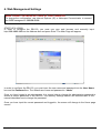
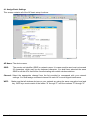
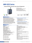
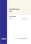
Contents
1. Introduction ............................................................................................................... 3
2. Features ..................................................................................................................... 4
3. Hardware Installation................................................................................................ 5
4. Web Management Settings ...................................................................................... 6
4.1 Assign Basic Settings....................................................................................................................... 7
4.2 Advanced Setting ........................................................................................................................... 10
4.3 Log ................................................................................................................................................. 13
4.4 STATUS ......................................................................................................................................... 14
4.5 Help................................................................................................................................................ 15
4.6 Password setting and Restore Factory Defaults ............................................................................ 16
5. How to install and launch the SNMP Manager ..................................................... 17
5.1 Login .............................................................................................................................................. 18
5.2 How to change the IP Address....................................................................................................... 19
5.3 Managing Security ......................................................................................................................... 20
5.4 Advanced setting............................................................................................................................ 21
5.5 Access Control (Authorized MAC Address) ................................................................................... 23
5.6 Change community string .............................................................................................................. 24
6. Reset device ............................................................................................................ 25
7 Technical specifications of RAYTALK RB-120....................................................... 26
User’s Guide
2
1. Introduction
Thank you for purchasing our RB-120 Wireless LAN Access Point. This manual will assist you with
the installation procedure.
The package you have received should contain the following items:
- User manual
- RB-120 Access Point
- Power adapter
- SNMP utility CD
Note: if anything is missing, please contact your vendor
A wireless LAN is normally used in a predefined environment. In such a network, Access Points are
mounted at assigned places, each covering its own area in which wireless nodes can operate. These
Access Points are connected to a wired network to communicate with each other and with servers and
clients on that network.
The RAYTALK RB-120 Access Point can be connected to a 10/100 Mbps Ethernet network through
a RJ45 (UTP) connector.
User’s Guide
3
2. Features
You can make use of WEB or SNMP utility software for connect RB-120 which you want to manage.
Supported features:
Restrict the authority of user to access WLAN and this unit.
Support IEEE 802.11 WEP encryption.
Optimizing the radio configuration via assign the independent spectrum.
Access Control and WEP encryption for network security.
Support powerful multi mode function in a same unit.
Access control table implemented via import or export with text file.
Wireless Repeater
User’s Guide
4
3. Hardware Installation
1. Mount the Access Point firmly to the wall or proper location that is determined during the site survey.
2. Make sure the antennas are in a vertical position (if not, rotate over 90 degrees).
3. Insert the power connector.
4. Attach the UTP Ethernet cable to the Access Point.
At the front of the Access Point you will see three LEDs.
If all goes well, the middle LED (power) and the lowermost LED(LINK) will fire and uppermost
LED(ACT) will flash whenever there is traffic on the respective networks which is at least ten times per
second for the wireless LAN because of so-called ‘beacons’.
You can reset the Access Point’s settings to factory defaults by pushing a paperclip in the little hole
next to the power connector.
User’s Guide
5
4. Web Management Settings
MAKE CORRECT NETWORK SETTINGS OF YOUR COMPUTER
To change the configuration, use Internet Explorer (IE) or Netscape Communicator to connect
the WEB management 192.168.5.100.
START UP & LOGIN
In order to configure the RB-120, you must use your web browser and manually input
http://192.168.5.100 into the Address box and press Enter. The Main Page will appear.
In order to configure the RB-120, you must input the user name and password into the User Name
box and the Password box. The default user name and password is “admin”.
Once you have logged-in as administrator, it is a good idea to change the administrator password to
ensure a secure protection to the RB-120. The Security Settings section will describe later in this
manual describes how to change the password.
Once you have input the correct password and logged-in, the screen will change to the Home page
screen.
User’s Guide
6
4.1 Assign Basic Settings
This screen contains all of the AP basic setup functions.
AP Name: The device name.
SSID:
The service set identifier (SSID) or network name. It is case sensitive and must not exceed
32 characters, which may be any keyboard character. You shall have selected the same
SSID for all the AP’s that will be communicating with mobile wireless stations.
Channel: Select the appropriate channel from the list provided to correspond with your network
settings. You shall assign a different channel for each AP to avoid signal interference.
WEP:
Make sure that all wireless devices on your network are using the same encryption level and
key. WEP keys must consist of the letters "A" through "F" and the numbers "0" through "9."
User’s Guide
7
Click Apply to save your settings.
LAN IP Address: This is the AP’s IP Address and Subnet Mask as seen on the internal LAN. The
default value is 192.168.5.100 for IP Address and 255.255.255.0 for Subnet Mask.
AP Mode: Working mode, there are four mode you can chose: Access Point, Access Point Client,
Wireless Bridge point to point, Wireless Bridge point to multipoint.
Backup/Restore Setting: You can backup or restore your settings
Click Backup to download your settings to your computer as following screen.
User’s Guide
8
Click Restore to upload your setting into AP, as following screen:
User’s Guide
9
4.2 Advanced Setting
Advanced have two settings: Wireless and MAC filtering.
Wireless setting contains the following setup functions:
Beacon Interval: The Beacon Interval value indicates the frequency interval of the beacon. Enter a
value between 20 and 1000. A beacon is a packet broadcast by the Router to synchronize the wireless
network. The default value is 100.
RTS Threshold: This value should remain at its default setting of 2346. Should you encounter
inconsistent data flow, only minor modifications are recommended. If a network packet is smaller than
the preset RTS threshold size, the RTS/CTS mechanism will not be enabled. The Router sends
Request to Send (RTS) frames to a particular receiving station and negotiates the sending of a data
frame. After receiving an RTS, the wireless station responds with a Clear to Send (CTS) frame to
acknowledge the right to begin transmission.
Fragmentation Threshold: This value specifies the maximum size for a packet before data is
fragmented into multiple packets. It should remain at its default setting of 2346. If you experience a
high packet error rate, you may slightly increase the Fragmentation Threshold. Setting the
Fragmentation Threshold too low may result in poor network performance. Only minor modifications of
this value are recommended.
DTIM Interval: This value indicates the interval of the Delivery Traffic Indication Message (DTIM). A
DTIM field is a countdown field informing clients of the next window for listening to broadcast and
multicast messages. When the Access Point has buffered broadcast or multicast messages for
associated clients, it sends the next DTIM with a DTIM Interval value.
Access Point Clients hear the beacons and awaken to receive the broadcast and multicast messages.
User’s Guide
10
Basic Rates: Select the Basic speed of transmission, there are “1-2”Mbps and “1 -2 -5.5 – 11”Mbps
you can chose.
Transmission Rates: The rate of data transmission should be set depending on the speed of your
wireless network. You can select from a range of transmission speeds, or you can select AUTO to
have the Router automatically use the fastest possible data rate and enable the Auto-Fallback feature.
Auto-Fallback will negotiate the best possible connection speed between the Router and a wireless
client. The default setting is AUTO.
Preamble Type: Select the head length of the packet.
Authentication Type:
Auto: Auto is the default authentication algorithm.It will change its authentication type automatically
to fulfill client’s requirement.
Open System: Open System authentication is not required to be successful while a client may
decline to authenticate with any particular other client.
Shared Key: Shared Key is only available if the WEP option is implemented. Shared Key
authentication supports authentication of clients as either a member of those who know a shared
secret key or a member of those who do not. IEEE 802.11 Shared Key authentication accomplishes
this without the need to transmit the secret key in clear. Requiring the use of the WEP privacy
mechanism.
Antenna Selection: Select the antenna.
SSID Broadcast: SSID broadcast control.
11
MAC filtering setting:
If you want to enable MAC filter, please click “Enabled” button.
Then you need to choose Deny or Allow PC’s whit MAC listed. And fill the MAC Address in the box
which you want to control.
Click “Apply” to save your setting.
12
4.3 Log
You can Enable or Disable Log function. You also can setup a computer to save the log file, click
“View Log” to check the log message.
User’s Guide
13
4.4 STATUS
The status page shows the information all about System and network status.
User’s Guide
14
4.5 Help
In this page you will get some information about how to use RAYTALK RB-120.
User’s Guide
15
4.6 Password setting and Restore Factory Defaults
Go to the Home page, click “password” to enter the setting page as the following:
Enter the new password and click “Apply” to save your setting.
Also, it provdes restore factory defaults setting 0n this tab. To perform this action, you can select
“Yes” then click “ Apply “ to restore default setting.
User’s Guide
16
5. How to install and launch the SNMP Manager
There is a CD which enclosed in this product. The SNMP software can be found on this CD. Please
install the SNMP Manager on your pc and change the IP address of your pc into 192.168.5.xxx subnet
for RB-120 configuration. The default IP of RAYTALK RB-120 is 192.168.5.100.
To make sure your pc and RB-120 whether in a same subnet and the connection is well, you can do
a test via “ping” command. For example, you can employ the following command “ping 192.168.5.100”
to check this connection is ok or not.
After launched the SNMP Manager, Please click the “Find Access Point”which under the “File” tab for
available AP searching. When find the available AP then press the “connect” button. Below is a figure
for a reference.
After completed the modified setting, please remember to save the result via click the “Download
Changes “which under the “File” tab.
Figure 1
User’s Guide
17
5.1 Login
When you got the available AP and press the connect button, there is a pop out window will come out.
You should import the community string and assign a role for administration. The default community
string is “public” and the Authority need to be an “Administrator”. Please refer to the Figure 2.
Notice: The capital letters and lowercase letters need to be differentiated.
Figure 2
User’s Guide
18
5.2 How to change the IP Address
If you wish to change the default IP address of RB-120, please click the tab “ Setup” “ Bridge” “ IP
configuration” as Figure3. With this table, please change the IP address what you expected.
Figure 3
IP Address: Please assign a unique IP address for this unit.
IP Mask: Please specify the proper subnet mask for this unit.
Gateway: There is a portal for packet incoming or outgoing which need to routing process.
DHCP Enable: The preferred method of providing IP addresses for your Access Points is
applying a DHCP server in your network. If you do and enable this setting, the Access Points will
acquire an IP address automatically from this server.
Primary Port: The major communication portal for configuration.
User’s Guide
19
5.3 Managing Security
Maintaining security in a wireless LAN environment is somewhat different from a wired network,
because the radio waves do not stop at your office walls. Eavesdropping or unauthorized access from
outside and your building can be a serious threat.
If you wish to enable the Privacy Options function, please click the “Setup” “Wireless LAN”
“Privacy Options” and choose the encryption method. The encryption key should follow the
hexadecimal format. The characters are only included “0” to “9” and “a” to “f”.
Figure 4
User’s Guide
20
5.4 Advanced setting
You can change the settings such as ESSID, channel, operational mode and so on via the advanced
setting. To click the “Setup” ” Wireless LAN” “Operational Settings”. Regarding the detail setting and
parameters, it will show on the following table. You can assign the proper parameters to this unit for
good performance.
Figure 5
Access Point Name: The device name.
ESSID: Extended Service Set Identifier (Wireless Network Identifier) is the group name that will
be shared by every member of your wireless network. You will only be able to connect with an
Access Point, which has the same ESS ID.
Channel: The channel selection. Via the setting to assign the proper channel for AP.
Fragmentation Threshold: The parameters of fragmentation.(default value: 2346)
RTS Threshold: The parameters of RTS setting.(default value: 2346 )
Authentications Type:
Open System: Open System is the default authentication algorithm. Open System
authentication is not required to be successful while a STA may decline to authenticate with
any particular other STA.
Shared Key: Shared Key is only available if the WEP option is implemented. Shared Key
authentication supports authentication of STAs as either a member of those who know a
shared secret key or a member of those who do not. IEEE 802.11 Shared Key authentication
accomplishes this without the need to transmit the secret key in clear. Requiring the use of
the WEP privacy mechanism.
Preamble Type: Two different preambles are defined. One is short type and the other is long type.
User’s Guide
21
Regulatory Domain: There is a specification of Regulatory Domain in this field.
Auto Rate Fall Back: The data rate will be changed automatically once the link distance with
change from AP to client. The adequate rate is going to fit via system while this setting is enabled.
Rates: There are four kinds of rates can be selected.
Access Point: This mode provides access for wireless stations to wired LANs and from wired
LANs to wireless stations.
Access Point Client: The function is same as normal wireless NIC. It can associate any Wi-Fi
compliant AP with Preferred BSS.
Wireless Bridge: This mode allows the connection of one or more remote LANs with a central
LAN.
Wireless Repeater: This mode you can extend the range of your network without having to use
cables to link access Point. For this application, please refer to the following figure.
Note: This operational mode will take effect after apply this setting 2~3 minutes.
Both of these units must have same SSID. The ethernet port on Repeater unit will only
for configuration.
User’s Guide
22
5.5 Access Control (Authorized MAC Address)
The IEEE 802.11 standard allows for Access Control rules based on the client station’s hardware
address, and is fully implemented by the RB-120.
The Mac address table can be specified with a text file format. Then using the “ Authorized Mac
Address “ which under the “ Setup” “ Wireless LAN “ to import or export the Mac address which would
like to control.
The MAC address format in text file should be followed as below:
EX: 00904b001234
00904b001235
Figure 6
User’s Guide
23
5.6 Change community string
The default community string is “public”. All of the setting can be changed only the import string is fit
with system.
There are two kinds of authorities can connect to this unit. One is Administrator the other is general
user. The community string can be changed by this pop out window. You just fill out the new string on
the following field as figure 7.
Notice: Only with Administrator role could change the setting of this unit.
Figure 7
User’s Guide
24
6. Reset device
This unit can be reset to factory defaults by reset hole and the procedure can be done with the
following steps.
Step1: You can reset the Access Point’s settings to factory defaults by pushing a paperclip in the little
hole next to the UTP port while the Access Point is on and do not release it right away.
Step2: Release the reset button when the “ACT” LED from burning to blinking. Normally, it may take
5~10 seconds. After release the reset button, the unit has been reverted to default setting.
User’s Guide
25
7 Technical specifications of RAYTALK RB-120
7.1 Standards supported
IEEE 802.11 standard for Wireless LAN
All major networking standards (including TCP/IP, NetBEUI, IPX)
7.2 Environmental
Operating temperature (ambient):
0 ~ 55°C
Humidity:
Max. 95% Non-condensing
7.3 Power Specifications
Input: AC 100-240 50-60 Hz 1A
Output: DC5V 0.5A
7.4 Radio Specifications
Range:
Per cell indoors approx. 30-100 meters
Per cell open space approx. 100-300 meters
Antenna:
Single antenna system, 2dBi gain, with swivel neck
Transmit power:
+14dBm
Frequency range:
2.4-2.4835 GHz, direct sequence spread spectrum
Number of Channels:
Most European countries: 13
US and Canada: 11 (3 non-overlapping)
France: 4 (1 non-overlapping)
Japan: 14
7.5 Specific Features
Supported bit rates:
11 Mbps: CCK
5.5 Mbps: CCK
1 Mbps: DBSK
2 Mbps: DQPSK
Data encryption:
64-bits WEP Encryption
128-bits WEP Encryption
Utility Software:
Web management
SNMP Manager
7.6 Physical Dimensions
103mm x 145mm x 30mm
User’s Guide
26