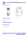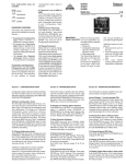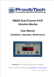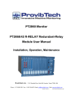
1
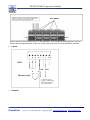
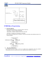
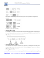
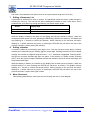
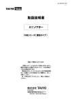
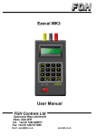
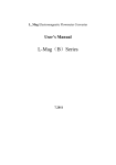
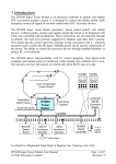
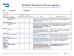
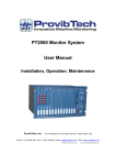
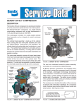
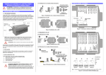
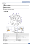
DTM30 TEMP Temperature Module
User Manual
Installation, operation, maintenance
ProvibTech, Inc.
11011 Brooklet Drive, Suite 360, Houston, Texas 77099, USA
Phone: +1-713-830-7601, Fax: +1-281-754-4972, Email: [email protected] , Web: www.provibtech.com
DTM30-USR/E-A-1
COPY RIGHT PROVIBTECH 2009
DTM30 TEMP Temperature Module
Contents
General Information................................................................................................................................................ 2
Features ................................................................................................................................................... 2
Specification............................................................................................................................................. 2
Case Dimensions(mm) ..................................................................................................................... 5
Ordering information............................................................................................................................... 5
DTM30 Installation .................................................................................................................................................. 5
DIN Rail Mounting................................................................................................................................... 5
DTM30 Operation ................................................................................................................................................... 6
Wiring Diagram........................................................................................................................................ 6
DTM30 Menu Programming .................................................................................................................. 8
DTM30 Maintenance ............................................................................................................................................ 13
Introduction ............................................................................................................................................ 13
Regular Maintenance ........................................................................................................................... 13
Preparation............................................................................................................................................. 13
Test.......................................................................................................................................................... 13
DTM30 Default configuration .............................................................................................................................. 14
ProvibTech
Phone: +1-713-830-7601 Fax: +1-281-754-4972 [email protected] , www.provibtech.com
-1-
DTM30 TEMP Temperature Module
General Information
The DTM30 is a totally new concept in DIN rail signal conditioning and consists of a family of DIN rail
modules, each one having a high degree of functionality and configurability. They accept all common
signals and have a choice of output options including an isolated (0 or 4 to 20) mA re-transmission
signal, change over trip relay, twin normally open relays or various combinations. For systems that
require more local input, single channel versions with an in-built keypad and digital display are
available where functions can be accessed via the front panel keys.
Each unit comes complete with a RS485 serial communications port which enables DTM30 to be
integrated into a complete process control system. Unit wiring is simplified and speeded up by using
the integral 'power / comms rail' system provided with each unit which removes the need for
complicated and expensive back plane wiring.
Features
z
Input/output/power isolation
z
Low power, long life
z
Hot plugging
z
35mm DIN rail mounting
Specification
1. Input
DTM30 units can accept the following input types.
Input
Ranges available
RTD
Pt100, Ni120
Thermocouple
K, J, T, R, S, E, F, N, B
1.1 RTD
ProvibTech
Phone: +1-713-830-7601 Fax: +1-281-754-4972 [email protected] , www.provibtech.com
-2-
DTM30 TEMP Temperature Module
Sensor range
-200 to 850°C
Linearization
Pt100(BS EN 60751/JISC
1604)/Ni120/Custom
Basic accuracy
0.1°C ± 0.05% of reading
Thermal drift (zero)
±0.004Ω/°C
Thermal drift (span)
100ppm/°C
Excitation current
1mA
Lead resistance effect
0.002 °C/Ω
Max lead resistance
50Ω/leg
1.2 Thermocouple
Type
Range(°C)
K
-200 to 1370
J
-200 to 1200
T
-210 to 400
R
-10 to 1760
S
-10 to 1760
E
-200 to 1000
F
-100 to 600
N
-180 to 1300
B
-10 to 1650
Custom
user defined
Basic accuracy
Linearization
Cold junction error
Cold junction tracking
Cold junction range
Thermal drift (zero)
Thermal drift (span)
± 0.04% FS or ± 0.04% reading or ±0.5°C, whichever is greater(For
type R & S, stated accuracy only applies between 800
&1760°C)(For type B, stated accuracy only applies between 400 &
1650°C)
BS4937 / IEC 584-3 / Custom
±0.5°C
0.05°C/°C
-20 to 70°C
± 4µV/°C
± 200ppm /°C
2. Outputs
2.1 Relays
Two relay options are available, either a single changeover or twin independent relays with
normally closed contacts. Contacts are Normally Closed i.e. the contact is open at power off and
when operating in the absence of an alarm condition. The contact closes when an alarm is
ProvibTech
Phone: +1-713-830-7601 Fax: +1-281-754-4972 [email protected] , www.provibtech.com
-3-
DTM30 TEMP Temperature Module
detected.
Alarm Action
Off, High, Low, Deviation, Test
Hysteresis
Programmable 0 to 100%
Delay Time
Programmable (Alarm must be continuously present for this
period in order to be recognized)
Start-up Delay
Programmable
AC
DC
Max switching voltage
48V RMS
48V
Max current
1A @48V
1A @ 30V
Max power
60VA
30W
Operate time
<5ms
Electrical life @ full load
100,000 operations
Mechanical life
10,000,000 operations
2.2 Current Retransmission
Output Range
0-10, 0-20, 4-20 mA source or sink
Maximum current output
<23mA
Accuracy
0.07%
Max power supply
30V (In sink mode)
3. General
EMC Approval
Immunity
Response Time
Power Requirements
Isolation
Ambient operating range
Ambient storage
Ambient humidity
EMC emissions
EMC immunity
Display Range
ProvibTech
EN61326: 1997
Annex A Industrial
300mSec typical
24V DC ±10% @200 mA
500V AC I/P~O/P~PSU
-30 to 60°C
-50 to 85°C
10 to 90% RH
BS EN50081-1
BS EN50082-2
-1999 to 9999
Phone: +1-713-830-7601 Fax: +1-281-754-4972 [email protected] , www.provibtech.com
-4-
DTM30 TEMP Temperature Module
Case Dimensions(mm)
Outputs
O/P1 RE-TRAN O/P2 N/C RELAY
PROVIBTECH
DTM30
Temperature Module
Inputs
Ordering information
DTM30-AX
A0:Basic module
DTM30 Installation
DIN Rail Mounting
35mm DIN rail mounting
ProvibTech
Phone: +1-713-830-7601 Fax: +1-281-754-4972 [email protected] , www.provibtech.com
-5-
DTM30 TEMP Temperature Module
Care must be taken when installing units into an enclosure to ensure that the ambient temperature
range is not exceeded. Power supply units can produce heat and if possible are best mounted in a
separate enclosure away from the DTM30 units.
DTM30 Operation
Wiring Diagram
1.
Power / Comms
POWER
O
DTM30 is provided with a unique ‘BUS JUMPER’ system for quick wiring of communications and
power connections. To use the Bus Jumper, disconnect all power supply/communications connectors
and place them so that they connect between the two units. Wiring to one connector then connects to
all units.
ProvibTech
Phone: +1-713-830-7601 Fax: +1-281-754-4972 [email protected] , www.provibtech.com
-6-
DTM30 TEMP Temperature Module
Ensure that the power supply is correct for the application. Over-voltage could damage the instrument.
Ensure that the exposed section of the wire is fully inserted and that no loose strands are exposed.
2.
Inputs
Discrete 2
Thermocouple
Discrete 1
RTD
A separate power
supply is required for
discreteif isolation is
to be maintained
3.
Outputs
ProvibTech
Phone: +1-713-830-7601 Fax: +1-281-754-4972 [email protected] , www.provibtech.com
-7-
DTM30 TEMP Temperature Module
Active
2 Relays closed in
Alarm and at Power off
Retransmitted Current
+19V to Power Loop on PIN 8
RLY1
RLY2
Passive
DTM30 Menu Programming
1. Operating Modes
All single channel DTM30 has 3 operating modes. These are:
• Run Mode – Process Variable is displayed.
• Menu Mode – Enables navigation around menu structure.
• Edit Mode – Enables menu parameters to be edited.
Run mode is the principal mode of operation. The other two modes are accessed as shown in the
following diagram.
2.
Key Press Definitions
Each DTM30 unit has 3 keys (A, B & C) to enable menu programming. Each key pressed
individually produces the following menu action (shaded square signifies key pressed ):
ProvibTech
Phone: +1-713-830-7601 Fax: +1-281-754-4972 [email protected] , www.provibtech.com
-8-
DTM30 TEMP Temperature Module
Keys pressed simultaneously produce the following menu actions (shaded square signifies key
pressed):
A: red key, B: green key, C: blue key.
3. Entering Menu Mode
On power up, the unit(s) will take a few seconds to configure itself. Run mode will then automatically
be entered. Menu mode is accessed from run mode by pressing ENTER followed by CYCLE. The
user will then be able to move around the root menu.
4. Root Menu
5. Navigating Around the Menu
The user can navigate around the root menu (or any sub-menu) by pressing the CYCLE key. Menu
navigation wraps around at the end of the menu list. The items displayed in the menu can either be
submenus, parameter lists or numbers
6. Entering a Sub-Menu
Pressing SHIFT enters the sub-menu or enables parameter list/number editing, depending on
where the menu structure is currently being pointed. If the menu navigation is pointing at a
ProvibTech
Phone: +1-713-830-7601 Fax: +1-281-754-4972 [email protected] , www.provibtech.com
-9-
DTM30 TEMP Temperature Module
sub-menu, the subsequent sub-menu can then be cycled around using the CYCLE key.
7. Editing a Parameter List
A parameter is selected from a list of options. The parameter option list can be cycled through by
pressing the INC key. The user will be able to distinguish between a menu cycle action, and a
parameter list cycle action by having the following 2 dynamic display styles:
Action
Display Style
Menu Cycle
Display scrolls on cycle press, no flash
Parameter List Cycle
Flash display at 1Hz
While the display is flashing, the option on the display has not been saved to memory. When the
desired parameter option is in view, pressing the ENTER key will save it to memory. The display will
stop flashing for 1 second to confirm the selection, before returning to the previous sub-menu.
Waiting for 1 minute without a key press, or pressing the ESCAPE key will return the user to the
previous submenu, without saving the selection.
8. Editing a Number
A number is edited by incrementing each digit in turn. The user will know which digit is currently
selected for incrementing by the flashing (@1Hz) of that digit. Pressing the INC key will increment
the digit. On overflow, the digit will wrap around to ‘-‘ or ‘0’, whichever is applicable. Pressing SHIFT
will shift the currently selected digit right one place. If the number is a whole number, pressing
SHIFT when the right most digit is selected will wrap the selection around to the left most digit, and
the process starts again.
While the display is flashing, the number on the display has not been saved to memory. When the
desired number is in view, pressing the ENTER key will save it to memory. The display will stop
flashing for 1 second to confirm the saved number, before returning to the previous sub-menu.
Waiting for 1 minute without a key press, or pressing the ESCAPE key will return the user to the
previous submenu, without saving the number.
9. Menu Structures
This following describes the menu tree structure through the use of a tree-diagram.
ProvibTech
Phone: +1-713-830-7601 Fax: +1-281-754-4972 [email protected] , www.provibtech.com
- 10 -
DTM30 TEMP Temperature Module
Elec
low
R
G
G
B
B
Select
Input Type
Elec lo Elec hi
4mA
20mA
0mA
20mA
0mA
10mA
Elec
high
R
Disabled when
menu type is short
First menu item
accessed
Key
R
START
Range
4-20mA
± 20mA
± 10mA
If current input type is selected,the electrical
high/low input values are set as follows.
Eng
hi
Eng
lo
Elec lo Elec hi
0V
0.1V
0V
10V
0V
1V
0V
3V
1V
5V
If voltage input type is selected, the electrical
high/low input values are set as follows.
Range
± 0.1V
± 10V
± 1V
± 5V
1-5V
if TC/RTD input selected. Defines
whether. in the event of a sensor
burnout, the output current goes
high (21.5mA) or low (3.6 mA)
FILTER FACTOR
There are 3 types of filter available:
1. Fixed filter - With a fixed filter applied the
filter time constant (TC) is equal to the filter
factor.
2. Adaptive Filter - When an adaptive filter
is applied, the filter time constant adapts to
the dynamic behaviour of the input signal.
When user linearisation is selected,linear
interpolation data can be entered.
G
B
R
G
Input
B
Type
Range
Linear
Unit
Decimal Point
Engineering Low
Engineering High
Bumout
Filter
User
Linearisation
R
This sub-menu contains prompts for
the X (in) & Y (out) co-ordinates.
The X values are the electrical
input values. The Y values are
corresponding engineering values.
G
R
G
B
Each key pressed individually
produces the following menu
action (shaded square
signifies key pressed):
R
S
Pt100
Japenese
/USA
Power
3/2
Current
E
N
Degree F
F
User
Defined
Power
5/2
Voltage
Key pressed simutaneously
produce the following menu
actions(shaded square
signifies key pressed):
Thermo
couple
Square
Root
T
B
User
Defined
G
B
B
B
B
Inc
Shift
Cycle
R
G
Clear
Enter
Escape
G
B
B
G
G
R
G
R
R
User
Defined
0 = Adaptive
0.1 = off
Displayed if CURRENT
input selected
Displayed if VOLTAGE
input selected
R
R
Each DTM30 unit has 3keys(A,B&C) to enable menu
programming.
Key Press Definitions
B
RTD
NoneLinear
J
PT100
Nical 20
European
K
Degree C
Only available if TC/RTD input
selected
Enter Value
Enter Value
Enter Value
Number of interpolated segments=
between 1& 59
Enter Value
Enter Value in seconds
Segments
Enter
Enter Value
B
Type
Span
Full Scale Low
Full Scale high
Level
High Alarm
Output 1
R
R
G
Preset
G
B
B
If "
" is chosen, the output
current can be edited in "
".
Otherwise, the retransmitted
current is derived linearly from the
process variable, using "
"&
"
"
Retran
Enter Value
Enter Value
Enter Value
The Setpoint value defines
the engineering value
associated with an alarm.
Low Alarm
Hysteresis
Hysteresis
Not Triggered
Triggered
Hysteresis
Hysteresis
Not Triggered
Triggered
R
B
G
Deviation
Relay
Latch
Alarm Delay
Hysterisls
Alarm Action
Setpoin A
G
Output 2
B
G
B
Deviant
Alarm
Test
Sets Relay Sense
Edit Stpoints
When set to " ", the
EDIT SETPOINTS sub
menu can be accessed
directly from RUN
mod.
If enabled (
submenu), and if a relay
output card is fitted,this
menu gives access to the
relevant alarm setpoints,
1A, 1B, 2A and 2B
R
G
Run Mode Options
When latch is enabled. an alarm
will remain triggered until it is
manually cleared
The alarm will not trigger until the PV has been in the
alarm region for more than this number of seconds
This value is used to offset the scaled process variable by a
fixed amount.
When accessing the menus from RUN mode,the user is
prompted for his passcode. If it is zero (default),there is
no prompt. and password function is disabled
The function of the discrete input
is to minic that of a
CLEAR button press. This menu item selects whether the clear
function is executed when the discrete is high (24V) "
" or
low(0V) "
"
DTM30 output will not be asserted until STD
(measured in seconds) has expired. DTM30
enforces the condition: 5 <= SDT <= 3600
When "
" type is chosen, access to greyed-out menu items is
restricted.To allow access to these items,choose "
" menu type.
Defines comms baud rate, displayed in kbps.
Defines 4 (full duplex) or 2
(half duplex) wire
communications mode
When the correct
is set, the device
address can be set to any value between 0 and
247, thus enabling multi-drop comms
Each DTM30 unit has a correct
associated with it. When
the correct
is set this menu item becomes inaccessible. and
the user is able to set a no-zero device address.
The format of the output menus
varies according to the output
card fitted. The 3 possible
output types are:
1. Current Retransmission
2. Changeover Relay(A)
3. Twin Relay (A & B)
Output menu 1/2 will vary
accordingly.
R
High
Alarm
Enter Value
Low
Alarm
Enter Value
Enable
Enter Value
de-energized energized
Disable
Enter Value in seconds
Off
There are two alarms (A&B)
so the following relay submenu
will be duplicated for alarm B.
Relay Output Menu
R
MENU TREE DTM30
G
RTX Output Menu
R
Alarm Action
Alarm Behaviour
always off
alarm triggers when PV<setpoint
alarm triggers when PV>setpoint
alarm triggers when PV moves out of deviation band
alarm on
PV
The hysterisis value is the difference between the points at which the
alarm triggers and releases, expressed in the relevant engineering unit
Setpoint
Alarm Function
Deviation Alarm
Deviation
Setpoint
Deviation
Alarm
Function
If "
" action is chosen, value determines the amount by
which the PV may change before the alarm is triggered, in
the engineering unit
G
G
B
B
B
B
Inc
Show
Valley
R
System
Network Enable
Password
Device Address
Line
BAUD Rate
Type
Startup Delay
Time
Discrete Active
Level Select
Menu Access
Passcode
User Offset
Enable Submenu
Clear Valley/Peak
G
B
Enter Password
G
(0-247)
default:0
Enter Value in
seconds
(0-9999)
default: 0000
Enter Offset
Clear Latch
Show
Peak
G
B
Shift
R
G
If enabled, pressing
CLEAR will 1. clear the
stored Peak/valley
readings 2. clear any
latched alarms.
B
Perform
Clear
Function
This is the normal runtime
mode where the PV is
displayed to the chosen
resolution
Clear
R
When set to " ", latched
alarms can be cleared.
Run Mode
When set to " ", valley/peak
reading can be cleared
R
Cycle
Escape
To enter menu mode from
RUN mode,the user
should press ENTER
followed by CYCLE
Shortcut
edit
setpoints
R
R
Phone: +1-713-830-7601 Fax: +1-281-754-4972 [email protected] , www.provibtech.com
- 11 -
ProvibTech
DTM30 TEMP Temperature Module
10. Select Menu Type
When “SHRT” type of the “TYPE” under the “SYS” menu is chosen, access to greyed out menu
items is restricted. To allow access to these items, choose “FULL” menu type.
11. Set Input Type
In the “TYPE” under the “INPT”, the user can set input type(RTD,Thermocouple).
12. Set Input Linear
In the “LIN” under the “INPT”, the user can set input linear.
¾
RTD: PT100 European, Nical 20, Pt100 Japenese/USA, User Defined;
¾
Thermocouple: K, J, T, R, S, E, F, N, B , User Defined.
13. Set the Temperature Unit
In the “UNIT” under the “INPT”, the user can set the temperature unit to degree C or degree F.
14. Set Output Current
In the “SPAN” under the “OUT1”, the user can set output current (4-20 mA, 0-20 mA, 0-10 mA).
15. Set Full Scale
In the “RTLO” under the “OUT1”, the user can set full scale low;
In the “RTHI” under the “OUT1”, the user can set full scale high.
16. Set Relay Alarm
¾
In the “ACT” under the “OUT2”, the user can set alarm action(off, low alarm, high alarm, test);
¾
In the “SET” under the “OUT2”, the user can set alarm setpoint;
¾
In the “HYS” under the “OUT2”, the user can set alarm hysterisis;
¾
In the “DEL” under the “OUT2”, the user can set alarm delay;
¾
In the “LCH” under the “OUT2”, the user can set alarm latch;
¾
In the “INU’ under the “OUT2”, the user can set relay energized/de-energized;
¾
In the “DEU” under the “OUT2”, the user can set alarm deviation.
17. Set Startup Delay Time
In the “STRT” under the “SYS”, the user can set startup delay time.
ProvibTech
Phone: +1-713-830-7601 Fax: +1-281-754-4972 [email protected] , www.provibtech.com
- 12 -
DTM30 TEMP Temperature Module
DTM30 Maintenance
Introduction
This section describes how to test whether the DTM30 is normal work.
Regular Maintenance
Recommend once maintenance of DTM30 one year. In addition, according to the actual situation
users should shorten the maintenance interval.
Preparation
Detect DTM30 required the following tools:
process calibrator;
Potentiometer;
Multimeter;
24VDC power supply;
Wire.
Test
1. RTD test:
Connect the potentiometer to DTM30, detected whether the output current and display is in the
range of permit.
The respective accuracies of the three main specification types, BS.EN 60751 Class A, BS.EN
60751 Class B and 1/10th Class B. Pt100 Platinum Resistance sensors are as shown in the
tolerance table below.
Resistance at 38.51
fundamental interval
ohms
Tolerances for 100 ohms Thermometers
Temperature
Class A
Class B
1/10 Class B
℃
℉
ohm
±℃
±ohm
±℃
±ohm
±℃
±ohm
-200
-328
18.52
0.55
0.24
1.3
0.56
0.13
0.06
-100
-148
60.26
0.35
0.14
0.8
0.32
0.08
0.03
0
32
100.00
0.15
0.06
0.3
0.12
0.03
0.01
100
212
138.51
0.35
0.13
0.8
0.30
0.08
0.03
200
392
175.86
0.55
0.20
1.3
0.48
0.13
0.05
ProvibTech
Phone: +1-713-830-7601 Fax: +1-281-754-4972 [email protected] , www.provibtech.com
- 13 -
DTM30 TEMP Temperature Module
300
572
212.05
0.75
0.27
1.8
0.64
0.18
0.06
400
752
247.09
0.95
0.33
2.3
0.79
0.23
0.08
500
932
280.98
1.15
0.38
2.8
0.93
0.28
0.09
600
1112
313.71
1.35
0.43
3.3
1.06
0.33
0.10
700
1292
345.28
3.8
1.17
800
1472
375.70
4.3
1.28
2. Thermocouple test:
Connect the process calibrator to DTM30, detected whether the output current and display is in the
range of permit.
DTM30 Default configuration
There is a reset button on the underside of every DTM30 unit, accessible with a small screwdriver
via the lower case vents. In order to reset all configuration settings, this button must be pressed with
power off, then remain pressed for 1 second after power-on. This will reset almost all configuration
settings to their default states, as the following sections show. Any configuration setting not listed
here will be unaffected when performing a reset. A reset is irreversible, and must be performed with
caution.
1. General Configuration
Discretes active level:
high
Clear peak / valley:
disabled
Clear latched alarms:
disabled
Edit setpoints:
disabled
Menu type:
short
Display resolution:
1 decimal place
2. Input(s) Configuration
Each of the following applies for each input channel.
Input type:
RTD
Linearization type:
Pt100(BS EN 60751)
Input unit:
Degree C
Filter factor:
0.1 (i.e. no filter applied)
Burnout:
Low
3. Outputs Configuration
Output startup delay:
5 seconds
Each of the following applies to each alarm/relay output.
Setpoint:
50/75℃
Hysteresis:
2℃
Deviation:
0
Alarm delay:
3s
Alarm action:
High alarm
ProvibTech
Phone: +1-713-830-7601 Fax: +1-281-754-4972 [email protected] , www.provibtech.com
- 14 -
DTM30 TEMP Temperature Module
Latch configuration:
latched
Alarm-relay:
de-energized
Each of the following applies to each retransmitted current output
Retransmission type:
Retransmission (not preset)
Span:
4-20mA
Full scale low/high:
0/100℃
Preset level:
10mA (This level will only be applied when ‘preset’ type is
selected)
ProvibTech
Phone: +1-713-830-7601 Fax: +1-281-754-4972 [email protected] , www.provibtech.com
- 15 -