1
CC-Link IE
Controller Network
Interface Board
User’s Manual
(Hardware)
Q80BD-J71GP21-SX
Q80BD-J71GP21S-SX
Thank you for purchasing the Mitsubishi program logic controller
MELSEC series.
Prior to use, please read this and relevant manuals thorougly to fully
understand the product.
MODEL CCIECONTROL-B-SW1-H
MODEL
13JY32
CODE
IB(NA)-0800386-F(1005)MEE
© 2007 MITSUBISHI ELECTRIC CORPORATION
SAFETY PRECAUTIONS
(Be sure to read these instructions before using the product.)
Before using this product, please read this manual and the relevant manuals
carefully and pay full attention to safety to handle the product correctly.
In this manual, the safety precautions are classified into two levels:
"
WARNING" and "
CAUTION".
WARNING
Indicates that incorrect handling may cause
hazardous conditions, resulting in death or severe
injury.
CAUTION
Indicates that incorrect handling may cause
hazardous conditions, resulting in minor or moderate
injury or property damage.
Under some circumstances, failure to observe the precautions given under
"
CAUTION" may lead to serious consequences.
Make sure that the end users read this manual and then keep the manual in a safe
place for future reference.
A-1
[Installation Precautions]
WARNING
Shut off the external power supply for the system in all phases before
installing the board to or removing it from the personal computer.
Failure to do so may result in electric shock or cause the board to fail or
malfunction.
Do not touch any connectors while power is on. Doing so may cause electric
shock or malfunction.
CAUTION
Use the board in an environment that meets the general specifications in this
manual. Failure to do so may result in electric shock, fire, malfunction, or
damage to or deterioration of the product.
Do not directly touch any conductive parts and electronic components of the
board. Doing so may cause malfunction or failure of the board.
When installing the board, take care not to get injured by an implemented
component or a surrounding member.
Fix the board by tighten the board-fixing screws within the specified torque
range. Undertightening may cause drop of the component or wire, short
circuit, or malfunction. Overtightening may damage the screw and/or module,
resulting in drop, short circuit, or malfunction.
For the tightening torque of the board-fixing screws, refer to the manual
supplied with the personal computer.
Before handling the board, touch a conducting object such as a grounded
metal to discharge the static electricity from the human body. Failure to do so
may cause the board to fail or malfunction.
Securely insert the board into the PCI bus slot following the board installation
instruction of the personal computer.Incorrect insertion of the board may lead
to a malfunction, failure or drop of the board.
When installing the board, take care not to get injured by an implemented
component or a surrounding member.
When installing the board, take care not to contact with other boards.
Handle the board in a place where static electricity will not be generated.
Failure to do so may cause a failure or malfunction.
The board is included in an antistatic envelope.
When storing or transporting it, be sure to put it in the antistatic envelope.
Failure to do so may cause a failure or malfunction.
Do not drop or apply a strong impact to the board.
Doing so may cause a failure or malfunction.
A-2
[Wiring Precautions]
WARNING
Shut off the external power supply for the system in all phases before
installing the board or starting wiring.Failure to do so may result in electric
shock, damage to the product, or malfunction.
After installation of the board and wiring, attach the cover on the module
before turning it on for operation.Failure to do so may result in electric shock.
CAUTION
Check the rated voltage and pin-out before wiring to the external power
supply cable, and connect the cables correctly. Connecting a power supply
with a different voltage rating or incorrect wiring may cause a fire or failure.
Place the communication cable and the external power supply cable
connected to the board in a duct or clamp them. If not, dangling cables may
swing or inadvertently be pulled, resulting in damage to the board or cables
or malfunctions due to poor contact.
When disconnecting the cable from the board, do not pull the cable by the
cable part. Pulling the cable connected to the board may result in malfunction
or damage to the board or cable.
Prevent foreign matter such as dust or wire chips from entering the personal
computer. Such foreign matter may cause a fire, failure, or malfunction.
Do not install the external power supply or communication cables together
with the main circuit lines or power cables. Keep a distance of 100mm (3.94
in.) or more between them. Failure to do so may result in malfunction due to
noise.
Special skills and tools are required to connect the communication cable to
the connector plug, which is an exclusive product. When purchasing it,
please consult your local Mitsubishi representative. Incomplete connection
can result in a short, fire or malfunction.
Securely plug the communication cable to the connector of the board. Then,
check for any incomplete connection. Poor contact may cause an erroneous
input or output.
Use a specified tool for crimping of the cable and contacting pin. Imperfect
crimping may cause a malfunction.
Verify the pin-out and fully insert the crimped contacting pin into the
connector. Imperfect insertion may cause a failure or malfunction.
Insert the wired external power supply cable into the external power supply
cable connector until a click is heard. Imperfect insertion may cause a failure
or malfunction.
A-3
[Wiring Precautions]
CAUTION
Always ground the personal computer to the protective ground conductor.
Failure to do so may cause a malfunction
[Disposal Precautions]
CAUTION
When disposing of this product, treat it as industrial waste.
A-4
CONDITIONS OF USE FOR THE PRODUCT
(1) Mitsubishi programmable controller ("the PRODUCT") shall be used in
conditions;
i) where any problem, fault or failure occurring in the PRODUCT, if any,
shall not lead to any major or serious accident; and
ii) where the backup and fail-safe function are systematically or
automatically provided outside of the PRODUCT for the case of any
problem, fault or failure occurring in the PRODUCT.
(2) The PRODUCT has been designed and manufactured for the purpose of
being used in general industries.
MITSUBISHI SHALL HAVE NO RESPONSIBILITY OR LIABILITY
(INCLUDING, BUT NOT LIMITED TO ANY AND ALL RESPONSIBILITY
OR LIABILITY BASED ON CONTRACT, WARRANTY, TORT, PRODUCT
LIABILITY) FOR ANY INJURY OR DEATH TO PERSONS OR LOSS OR
DAMAGE TO PROPERTY CAUSED BY the PRODUCT THAT ARE
OPERATED OR USED IN APPLICATION NOT INTENDED OR
EXCLUDED BY INSTRUCTIONS, PRECAUTIONS, OR WARNING
CONTAINED IN MITSUBISHI'S USER, INSTRUCTION AND/OR
SAFETY MANUALS, TECHNICAL BULLETINS AND GUIDELINES FOR
the PRODUCT.
("Prohibited Application")
Prohibited Applications include, but not limited to, the use of the
PRODUCT in;
• Nuclear Power Plants and any other power plants operated by Power
companies, and/or any other cases in which the public could be
affected if any problem or fault occurs in the PRODUCT.
• Railway companies or Public service purposes, and/or any other cases
in which establishment of a special quality assurance system is
required by the Purchaser or End User.
• Aircraft or Aerospace, Medical applications, Train equipment, transport
equipment such as Elevator and Escalator, Incineration and Fuel
devices, Vehicles, Manned transportation, Equipment for Recreation
and Amusement, and Safety devices, handling of Nuclear or
Hazardous Materials or Chemicals, Mining and Drilling, and/or other
applications where there is a significant risk of injury to the public or
property.
Notwithstanding the above, restrictions Mitsubishi may in its sole
discretion, authorize use of the PRODUCT in one or more of the
Prohibited Applications, provided that the usage of the PRODUCT is
limited only for the specific applications agreed to by Mitsubishi and
provided further that no special quality assurance or fail-safe, redundant
or other safety features which exceed the general specifications of the
PRODUCTs are required. For details, please contact the Mitsubishi
representative in your region.
A-5
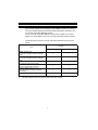
Revisions
* The manual number is given on the bottom right of the cover.
Print Date
Apr., 2007
*Manual Number
IB(NA)-0800386-A
Oct., 2007
IB(NA)-0800386-B
Jan., 2008
IB (NA)-0800386-C
Sep., 2008
IB (NA)-0800386-D
Jun., 2009
IB (NA)-0800386-E
May, 2010
IB (NA)-0800386-F
Revision
First edition
Correction
Chapter 5, Section 7.2, Chapter 8
Correction
SAFETY PRECAUTIONS, Manual, Chapter 1,
Chapter 2, Chapter 3, Chapter 4, Chapter 5,
Chapter 6, Chapter 7
Correction
Chapter 2
Correction
Chapter 1, Chapter 5
Addition
CONDITIONS OF USE FOR THE PRODUCT,
Section 2.1, Section 2.2
Correction
SAFETY PRECAUTIONS, Chapter 2, Section 3.1,
Chapter 4, Section 5.1.2, Section 5.1.3, Chapter 6,
Chapter 7, Section 7.1, Section 7.2
This manual confers no industrial property rights or any rights of any other kind, nor does it
confer any patent licenses. Mitsubishi Electric Corporation cannot be held responsible for any
problems involving industrial property rights which may occur as a result of using the contents
noted in this manual.
© 2007 MITSUBISHI ELECTRIC CORPORATION
A-6
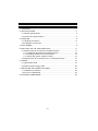
CONTENTS
1. OVERVIEW .................................................................................................... 1
2. SPECIFICATIONS .......................................................................................... 2
2.1 General specifications .............................................................................. 2
2.2 Performance Specifications...................................................................... 4
3. HANDLING ..................................................................................................... 6
3.1 Handling precautions................................................................................ 6
3.2 Installation environment ........................................................................... 7
4. PART NAMES ................................................................................................ 8
5. EMC AND LOW VOLTAGE DIRECTIVE ...................................................... 11
5.1 Requirements for conformance to EMC Directive .................................. 11
5.1.1 Standards applicable to the EMC Directive..................................... 12
5.1.2 Installing devices in the control panel ............................................. 13
5.1.3 Noise filter (power supply line filter) ................................................ 15
5.2 Requirements for conformance to Low Voltage Directive ...................... 15
6. WIRING ........................................................................................................ 16
6.1 Optical fiber cable................................................................................... 19
6.2 External power supply cable .................................................................. 20
7. INSTALLING SOFTWARE PACKAGES....................................................... 22
7.1 Installation procedures ........................................................................... 22
7.2 Icons to be Registered ........................................................................... 23
8. EXTERNAL DIMENSIONS ........................................................................... 24
A-7
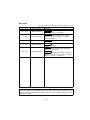
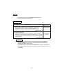
Manual
The following is the manual relevant to this product.
Please purchase it if necessary.
Relevant Manuals
Manual Number
(Model Code)
Manual Name
CC-Link IE Controller Network Reference Manual
This manual explains the system configuration, performance
specification, functions, handling and wiring instructions, and
troubleshooting of the CC-Link IE Controller network system.
(Sold separately)
CC-Link IE Controller Network Interface Board User's Manual
(For SW1DNC-MNETG-B)
This manual explains the system configuration, software package
installation and uninstallation, operating method for utilities, accessible
ranges and devices, and troubleshooting of the CC-Link IE Controller
Network board.
(Sold separately)
SH-080668ENG
(13JV16)
SH-080691ENG
(13JZ02)
Remarks
CC-Link IE Controller Network Interface Board User's Manual (For
SW1DNC-MNETG-B) is stored on CD-ROM of the corresponding
software package in PDF format.
A printed version of the manual is available as an option. Indicate the
manual No. (Model code) when placing an order for a printed version of
the manual.
A-8
1. OVERVIEW
This manual explains the handling of the Q80BD-J71GP21(S)-SX CCLink IE Controller Network interface board (hereinafter referred to as
CC-Link IE Controller Network board).
The CC-Link IE Controller Network board can be used as a control
station or normal station in the CC-Link IE Controller network system.
The packing list of the CC-Link IE Controller Network board is given
below.
Quantity
Item
Q80BD-J71GP21-SX
Q80BD-J71GP21S-SX
1
—
—
1
—
1
1
1
1
1
1
1
Q80BD-J71GP21-SX
CC-Link IE Controller Network interface
board
Q80BD-J71GP21S-SX
CC-Link IE Controller Network interface
board
Connector set
(for external power supply cable)
CC-Link IE Controller Network Interface
Board User's Manual (Hardware)
SW1DNC-MNETG-B CC-Link IE
Controller Network software package
(CD-ROM)*1
Software license agreement
*1
The CD-ROM contains the User's Manual in PDF format.
1
2. SPECIFICATIONS
General specifications and Performance specifications of the CC-Link
IE Controller Network board are shown below.
2.1 General specifications
(1) General specifications of the CC-Link IE Controller Network board
are shown below.
Item
Specification
Operating
ambient
0 to 55 °C
temperature
Storage ambient
temperature
-25 to 75 °C
Operating
ambient humidity
5 to 95 % RH, Condensation not allowed
Storage
ambient humidity
5 to 95 % RH, Condensation not allowed
Vibration
resistance
Shock resistance
Sweep
—
Frequency Acceleration Amplitude
Count
Conforming
—
0.075 mm
Intermittent 10 to 57 Hz
10 times
to
2
—
each in X,
JIS B3502, vibration 57 to 150 Hz 9.8 m/s
IEC61132-2 Continuous 10 to 57 Hz
—
0.035 mm Y and Z
axes
vibration 57 to 150 Hz 4.9 m/s2
—
Conforming to JIS B 3502, IEC 61131-2
(147 m/s2, 3 times each in 3 directions)
Operating
environment
No corrosive gas present
Operating
altitude*1
2000 m (6562 ft) or less
Installation area
In control panel
Overvoltage
category *2
II or lower
Pollution
degree*3
2 or lower
2
*1
The board cannot be used under the environment where the atmospheric
*2
It indicates that the device is to be connected to which power distribution
pressure is higher than the one at the altitude of 0 m.
part, within the area from the public electricity network to machinery in the
premise.
Category II applies to the devices to which power is supplied from fixed
installations.
The surge voltage withstand for devices rated up to 300 V is 2500 V.
*3
This is an index showing the degree of the conductive pollution that can
occur in the environment where the device is used.
In Pollution degree 2, only nonconductive pollution occurs. Occasionally,
however, temporary conductivity caused by condensation can be expected.
(2) General specifications of the CC-Link IE Controller Network board
or the personal computer, whichever are lower, must be satisfied
after installation.
3
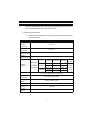
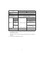
2.2 Performance Specifications
Performance specifications of the CC-Link IE Controller Network board
are shown below.
Item
LB
Max. link points LW
per network
LX
LY
LB
Max. link points
LW
per station
LX
LY
Transient transmission
capacity
Communications speed
Number of stations per
network
Connection cable
Overall cable distance
Min.
Station-tostation distance Max.
Max. number of networks
Max. number of groups
Transmission path
Communication method
Synchronization method
Encoding method
Transfer format
Error control system
RAS functions
Transient transmission
Specification
Q80BD-J71GP21-SX
Q80BD-J71GP21S-SX
32K points (32768 points, 4K bytes)
128K points (131072 points, 256K bytes)
8K points (8192 points, 1K byte)
8K points (8192 points, 1K byte)
Normal:16K points (16384 points, 2K bytes)
Extended mode:32K points (32768 points, 4K bytes)
Normal:16K points (16384 points, 32K bytes)
Extended mode:128K points (131072 points, 256K bytes)
8K points (8192 points, 1K byte)
8K points (8192 points, 1K byte)
Up to 1920 bytes
1G bps
120 stations (Control station: 1; Normal station: 119)
Optical fiber cable (Multi-mode fiber)
66000 m (When 120 stations are connected)
2m
550 m (Core/clad = 50/125 ( m))
239
32
Duplex loop
Token ring method
Flag synchronization (Frame synchronization)
8B10B
Ethernet II
FCS (Frame Check Sequence, CRC32 of the frame,
Ethernet-compliant)
Loop back function by error detection and cable disconnection,
System-down prevention by control station switching,
Error detection by link special relays and link special registers,
etc.
N: N communications
4
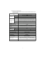
Item
Number of boards that can be
installed
Installation slot
Occupied slots
PCI bus performance
Voltage
Current
Specification
Q80BD-J71GP21-SX
Q80BD-J71GP21S-SX
Up to 4*1
PCI bus slot (Half size) or PCI-X bus slot (Half size)
1 slot
Bus width: 32 bit
Bus frequency: 33MHz
Bus voltage: 5V or 3.3 V DC (Universal PCI compliance)
20.4 V to 31.2 V DC
0.27 A
Connector
Applicable
cable size
External power Allowable
*2
supply
momentary
power failure
time
Connector set (Accessory)
0.50 to 1.25 mm2
[AWG#20-16]
(No external power supply)
1ms (level PS1)
Noise voltage: 500vp-p
Noise width: 1 s
(By the noise simulator with
noise frequency 25 to 60Hz)
Noise durability
5 V DC Internal current
consumption
Weight
*1
0.88 A
0.88 A
0.12 kg
0.14 kg
This indicates the number of CC-Link IE Controller Network boards that can
be installed to a personal computer, not including any other boards such as
MELSECNET/H boards.
Note that it cannot exceed the number of physical PCI slots of the personal
computer.
*2
Use the power complies with CLASS2.
5
3. HANDLING
This section explains precautions for handling and installation
environment of the CC-Link IE Controller Network board.
3.1 Handling precautions
The following explains precautions for handling the CC-Link IE
Controller Network board.
WARNING
Shut off the external power supply for the system in all
phases before installing the board to or removing it from
the personal computer. Failure to do so may result in
electric shock or cause the board to fail or malfunction.
Do not touch any connectors while power is on. Doing so
may cause electric shock or malfunction.
CAUTION
Do not directly touch any conductive parts and electronic
components of the board. Doing so may cause
malfunction or failure of the board.
When installing the board, take care not to get injured by
an implemented component or a surrounding member.
Fix the board by tighten the board-fixing screws within the
specified torque range. Undertightening may cause drop
of the component or wire, short circuit, or malfunction.
Overtightening may damage the screw and/or module,
resulting in drop, short circuit, or malfunction.
For the tightening torque of the board-fixing screws, refer
to the manual supplied with the personal computer.
Before handling the board, touch a conducting object such
as a grounded metal to discharge the static electricity from
the human body. Failure to do so may cause the board to
fail or malfunction.
Securely insert the board into the PCI bus slot following
the board installation instruction of the personal
computer.Incorrect insertion of the board may lead to a
malfunction, failure or drop of the board.
When installing the board, take care not to get injured by
an implemented component or a surrounding member.
When installing the board, take care not to contact with
other boards.
Handle the board in a place where static electricity will not
be generated.
Failure to do so may cause a failure or malfunction.
6
CAUTION
The board is included in an antistatic envelope.
When storing or transporting it, be sure to put it in the
antistatic envelope.
Failure to do so may cause a failure or malfunction.
Do not drop or apply a strong impact to the board.
Doing so may cause a failure or malfunction.
When disposing of this product, treat it as industrial waste.
3.2 Installation environment
For installation of the personal computer in which the CC-Link IE
Controller Network board is installed, refer to the manual for the
personal computer.
CAUTION
Use the board in an environment that meets the general
specifications in this manual. Failure to do so may result in
electric shock, fire, malfunction, or damage to or
deterioration of the product.
Always ground the personal computer to the protective
ground conductor.
Failure to do so may cause a malfunction.
7
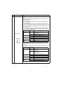
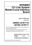
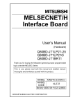
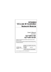
4. PART NAMES
This section explains each part name and setting of the CC-Link IE
Controller Network board.
(1) Q80BD-J71GP21-SX
1)
RUN ERR.
SD
IN
RD
2)
OUT
BD808C
317G51
(2) Q80BD-J71GP21S-SX
E.PW
E.PW
RUN
ERR.
4)
3)
1)
SD
IN
RD
2)
OUT
E.PW
+24VDC
24G
NC
BD808C
317G51
8
No.
Name
Indicator LED
1)
RUN ERR.
SD
RD
Description
Indicates the operating status of the CC-Link IE Controller Network
board.
The display format has three types: normal , error and channel
number confirmation.
(1) Normal status
When the RUN LED is OFF or ON, the LED display becomes
normal status.
If a communication error occurs in the status, determine the
error in Select station network device status display on the "CCLink IE Controller Network diagnostics result" screen of the CC
IE Control utility.
For the Select station network device status display, refer to
"CC-Link IE Controller Network Interface Board User's Manual
(For SW1DNC-MNETG-B)".
LED name
Status
Description
A WDT error occurred or the board
OFF
is
being
reset.
RUN
ON
In normal operation
OFF
Data has not been sent.
SD
ON
During data transmission
OFF
Data has not been received.
RD
ON
During data reception
OFF
No error
ERR.
ON
Error
(2) Error status
When the RUN LED is flashing, the LED display becomes error
status
If an error occurs in the status, check the error description on
the Event Viewer screen.
LED name
Status
Description
Indicates the display format is in
Flashing
error status.
RUN
Indicates the display format is in
ON
nomal status.
OFF
Refer to (1) in this table.
OFF
—
SD
ON
—
OFF
No driver response error
RD
ON
A driver response error occurred.
OFF
No PCI bus error
ERR.
ON
A PCI bus error occurred.
9
No.
Name
Description
(3) Channel number confirmation status
This status is for checking the channel No. of each board.
The LED displays the channel No. assigned to each board.
<151>
1)
<152>
<153>
<154>
RUNERR. RUNERR. RUNERR. RUNERR.
SD RD
SD RD
SD RD
SD RD
Connector for connecting optical fiber cable
(1) The cable terminal is as shown below.
IN Reverse loop transmission
2)
IN Forward loop reception
Optical fiber cable
connector
OUT Forward loop transmission
OUT Reverse loop reception
External power
supply LED
3)
E.PW
(2) For wiring of an optical fiber cable, refer to "CC-Link IE
Controller Network Interface Board User's Manual (For
SW1DNC-MNETG-B)".
Indicates the status of external power supply.
LED name
Status
Description
External power supply is not
OFF
supplied.
E.PW
External power supply is being
ON
supplied.
Connector for connecting external power supply cable
The cable terminal is as shown below.
4)
External power
supply cable
connector
(Board top)
24V
24G
E.PW
10
5. EMC AND LOW VOLTAGE DIRECTIVE
For the products sold in European countries, the conformance to the
EMC Directive, which is one of the European Directives, has been a
legal obligation since 1996. Also, conformance to the Low Voltage
Directive, another European Directive, has been a legal obligation since
1997.
Manufacturers who recognize their products must conform to the EMC
and Low Voltage Directives are required to declare that their products
conform to these Directives and put a "CE mark" on their products.
(1) Authorized representative in Europe
Authorized representative in Europe is shown below.
Name : Mitsubishi Electric Europe BV
Address: Gothaer strase 8, 40880 Ratingen, Germany
5.1 Requirements for conformance to EMC Directive
The EMC Directive specifies that products placed on the market must
"be so constructed that they do not cause excessive electromagnetic
interference (emissions) and are not unduly affected by electromagnetic
interference (immunity) ". The applicable products are requested to
meet these requirements.
The sections 5.1.1 through 5.1.3 summarize the precautions on
conformance to the EMC Directive of the machinery constructed using
the CC-Link IE Controller Network board.
The details of these precautions has been prepared based on the
control requirements and the applicable standards. However, we will not
assure that the overall machinery manufactured according to these
details conforms to the above-mentioned directives.
The final decision on the method for the EMC Directive conformance
and the application must be made by the manufacturer of the
machinery.
11
5.1.1 Standards applicable to the EMC Directive
The standards applicable to the EMC Directive are listed below.
All test items were tested by installing each device on a personal
computer bearing a CE certification logo.
Specification
EN61131-2:
2003
*1
Test item
Test details
Standard value
EN61000-6-4
Radiated noise
Measures
electromagnetic
emissions from the
product.
30M-230MHz QP: 30 dB V/m
(30 m in measurement range)*1
230M-1000MHz QP: 37 dB V/m
(30 m in measurement range)*1
EN61000-6-4
Conducted noise
Measures
electromagnetic
emissions from the
product to the power
line.
150k-500kHz QP: 79 dB, Mean: 66
dB*1
500k-30MHz QP: 73 dB, Mean: 60
dB*1
EN61000-4-2
Electrostatic
immunity
Immunity test in
which static
4 kV Contact discharge
electricity is applied
8 kV Aerial discharge
to the cabinet of the
equipment.
EN61000-4-4
Electrical fast
transient/ burst
immunity
Immunity test in
Power line: 2 kV
which a burst noise
Data communication: 1 kV
is applied to a power
Digital/Analog I/O (shielded): 1 kV
line and signal line.
EN61000-4-3
Radiated
electromagnetic
field immunity (AM
modulation)
Immunity test in
which a field is
irradiated to the
product.
10 V/m, 26-1000 MHz,
80%AM modulation@1 kHz
EN61000-4-6
Conducted
disturbances
immunity
Immunity test in
which a high
frequency noise is
applied to a power
line and signal line.
3V
EN61000-4-5
Surge immunity
Immunity test in
which a lightning
surge is applied to a
power line and
signal line.
Power line: 2 kV (CM), 1 kV (DM)
Data communication (shielded): 1 kV
(CM)
Digital/Analog I/O (shielded): 1 kV
(CM)
QP: Quasi-peak value, Mean: Mean value
12
5.1.2 Installing devices in the control panel
Installing devices in the control panel has a considerable effect, not only
securing safety but also shielding the noise generated from the personal
computer in the control panel.
(1) Control panel
(a) Use a conductive control panel.
(b) When attaching the control panel's top plate or base plate,
mask painting and weld so that good surface contact can be
made between the panel and plate.
(c) To ensure good electrical contact with the control panel, mask
the paint on the installation bolts of the inner plate in the
control panel so that contact between surfaces can be ensured
over the widest possible area.
(d) Ground the control panel with a thick wire so that a low
impedance connection to ground can be ensured even at high
frequencies.
(e) Holes made in the control panel must be 10 cm (3.94 in.)
diameter or less. If the holes are 10 cm (3.94 in.) or larger,
radio frequency noise may be emitted.
In addition, because radio waves leak through a clearance
between the control panel door and the main unit, reduce the
clearance as much as practicable. The leakage of radio waves
can be suppressed by the direct application of an EMI gasket
on the paint surface.
Maker name
Series type
KITAGAWA INDUSTRIES CO., LTD.
US series
ZIPPERTUBING (JAPAN) LTD.
71TS series
SEIWA ELECTRIC MFG CO., LTD.
E02S
A
Our tests have been carried out on a panel having the
damping characteristics of 37 dB max. and 30 dB mean
(measured by 3 m method with 30 to 300MHz).
13
(2) Connection of power and ground cable
The power supply cable and ground cable for a personal computer
should be laid out as follows:
(a) Provide a grounding point near the power supply of personal
computer. Ground the FG (frame ground) terminal of the
personal computer and the SLD (shield) terminal of the CCLink IE Controller Network board with the thickest and shortest
grounding wire (wire for grounding) possible (about 30 cm
(11.81 in.) or less in length). Since the FG and SLD terminals
function to ground the noise generated in the personal
computer, it is necessary to ensure the lowest possible
impedance.
As the wires are used to relieve the noise, the wire itself
contains a large amount of noise and thus short wiring
prevents from functioning as an antenna.
(b) Twist the ground cable leading to the ground point with the
power supply cable. By twisting it with the ground cable, the
noise leaking from the power supply cable may be grounded at
a higher rate. However, twisting the power supply cable with
the ground cable may not be necessary if a noise filter is
installed on the power supply cable.
14
5.1.3 Noise filter (power supply line filter)
A noise filter is a component which has an effect on conducted noise.
It is not required to fit the noise filter to the power supply line, but fitting it
can further suppress noise. (The noise filter has the effect of reducing
conducted noise of 10MHz or less.)
The precautions required when installing a noise filter are described
below.
(1) Do not bundle the wires on the input side and output side of the
noise filter.
When they are bundled, the output side noise will induct into the
input side wires.
Input side
(power supply side)
Input side
(power supply side)
Introduction
Filter
Filter
Output side
(device side)
(a) The noise will induct into input side when
the input and output wires are bundled.
Output side
(device side)
(b) Separate the input and output wires.
(2) Ground the ground terminal of the noise filter to the control panel
using as short wiring as possible (about 10 cm (3.94 in.)).
Remarks
Reference noise filters are shown below.
Noise filter type
FN343-3/01
FN660-6/06
ZHC2203-11
Maker name
SCHAFFNER
TDK
Rated current(A)
3
6
3
Rated voltage(V)
250
5.2 Requirements for conformance to Low Voltage Directive
The CC-Link IE Controller Network board is out of the requirement for
conformance to the Low Voltage Directive, since it does not use the
power supply in the range of 50 to 1000V AC and 75 to 1500V DC.
15
6. WIRING
This section explains precautions for connecting cables to the CC-Link
IE Controller Network board.
(1) Precautions for general wiring
WARNING
Shut off the external power supply for the system in all
phases before installing the board or starting
wiring.Failure to do so may result in electric shock,
damage to the product, or malfunction.
After installation of the board and wiring, attach the cover
on the module before turning it on for operation.Failure to
do so may result in electric shock.
CAUTION
When disconnecting the cable from the board, do not pull
the cable by the cable part. Pulling the cable connected to
the board may result in malfunction or damage to the
board or cable.
Prevent foreign matter such as dust or wire chips from
entering the personal computer. Such foreign matter may
cause a fire, failure, or malfunction.
Always ground the personal computer to the protective
ground conductor.
Failure to do so may cause a malfunction.
16
(2) Precautions for communication cable wiring
CAUTION
Place the communication cable and the external power
supply cable connected to the board in a duct or clamp
them. If not, dangling cables may swing or inadvertently
be pulled, resulting in damage to the board or cables or
malfunctions due to poor contact.
Special skills and tools are required to connect the
communication cable to the connector plug, which is an
exclusive product.
When purchasing it, please consult your local Mitsubishi
representative.
Incomplete connection can result in a short, fire or
malfunction.
Securely plug the communication cable to the connector
of the board. Then, check for any incomplete connection.
Poor contact may cause an erroneous input or output.
Remarks
For optical fiber cables, refer to the "CC-Link IE Controller Network
Reference Manual".
17
(3) Precautions for external power supply cable wiring
CAUTION
Check the rated voltage and pin-out before wiring to the
external power supply cable, and connect the cables
correctly. Connecting a power supply with a different
voltage rating or incorrect wiring may cause a fire or
failure.
Place the communication cable and the external power
supply cable connected to the board in a duct or clamp
them. If not, dangling cables may swing or inadvertently
be pulled, resulting in damage to the board or cables or
malfunctions due to poor contact.
Do not install the external power supply or communication
cables together with the main circuit lines or power cables.
Keep a distance of 100mm (3.94 in.) or more between
them. Failure to do so may result in malfunction due to
noise.
Use a specified tool for crimping of the cable and
contacting pin. Imperfect crimping may cause a
malfunction.
Verify the pin-out and fully insert the crimped contacting
pin into the connector. Imperfect insertion may cause a
failure or malfunction.
Insert the wired external power supply cable into the
external power supply cable connector until a click is
heard. Imperfect insertion may cause a failure or
malfunction.
Remarks
For details of the wiring method, refer to "CC-Link IE Controller Network
Interface Board User's Manual (For SW1DNC-MNETG-B)".
18
6.1 Optical fiber cable
The following explains precautions for connecting the optical fiber
cables with the Q80BD-J71GP21-SX and Q80BD-J71GP21S-SX.
(1) Precautions for connection
(a) Use the dedicated optical fiber cable shown below for the
controller network system.
Type
Model name (maker)
Multi-mode fiber (GI) QG series (Mitsubishi electric system & service Co., Ltd.)
(b) When connecting an optical fiber cable to the Q80BDJ71GP21-SX and Q80BD-J71GP21S-SX, the cable bend
radius is restricted.
For details, check the specifications of the cable used.
(c) When laying the optical fiber cables, do not touch the fiber
cores of the cable-side and board-side connectors, and protect
them from dirt and dust.
If oil from the hand, dirt or dust is attached to the core, it can
increase transmission loss, causing a problem in data link.
(d) When connecting or disconnecting an optical fiber cable, hold
the connector part of the cable.
(e) Make a full connection between the cable-side and board-side
connectors until a "click" can be heard.
(f)
When installing the Q80BD-J71GP21-SX or Q80BDJ71GP21S-SX to the personal computer, secure a space of
around 10 mm (0.39 in.) to the right and left of the optical
connector. Depending on the adjacent boards and installing
slot position, connecting/disconnecting the optical cable may
be difficult. In this case, use the following dedicated tool.
Model name
SCT-SLM
Maker
Mitsubishi electric system & service Co., Ltd.
CC-Link IE Controller Network board
Board-side connector
Cable-side connector
Connector hook
19
6.2 External power supply cable
This section explains the method for connecting external power supply
cable to the Q80BD-J71GP21S-SX.
(1) Parts and tools required for external power supply cable
The following parts and tools are required for making external
power supply cable.
(a) Connector set (accessories)
Check that the following parts are included with the attached
connector set.
Type
Connector
Contact
Model name
1-178288-3
175218-2
Applicable wire size
—
AWG#20-16
Quantity
1
3 (Spare 1)
(b) Cable
Use an external power supply cable with heat-resistant vinyl
sheath of 0.5 to 1.25 mm2 [AWG#20 to 16].
(c) Tool
Use the following specified crimp tools.
Model
91558-1
1762956-1
Applicable wire size
Inquiry
AWG#20-16
Tyco Electronics
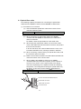
(2) Making external power supply cable
(a) Crimping a contacting pin
Using a crimp tool, crimp the cable and contacting pin.
Set the contacting pin and cable in the grooves of the crimp
tool, squeeze the handle, and make them stick together tightly.
For details of the crimp, refer to the instruction of the tool.
A strip length of the cable should be 5 to 7 mm (1/5 to 2/7 in.)
(b) Check for a crimp
Check if the cable (including a part of
the sheath) is evenly crimped to the
contacting pin.
If the cable part is crimped but not the
sheath part or the cable is stuck out,
the cable cut or a malfunction may
result.
20
Contacting pin
Cable
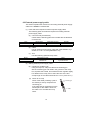
(c) Connecting to the connector
According to the following
pin-out, fully insert the
crimped cable to the
connector until a click is
heard.
Pin No.
1
2
3
Description
24V
24G
Open
Connector
Contacting pin
24V
24G
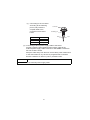
(3) Connecting external power supply cable to the board
Properly insert the wired external power supply cable to the
external power supply cable connector of the Q80BD-J71GP21SSX until a click is heard.
Keep the cable away from the main circuit cable, power cables and/
or the load cables for any other than programmable controllers.
Ensure a distance of 100 mm (3.94 in.) between them.
POINT
Be sure to twist the external power supply cable.
21
7. INSTALLING SOFTWARE PACKAGES
This chapter explains about installing the software packages and icons
to be registered.
For details of the installation procedure and the uninstallation method,
refer to "CC-Link IE Controller Network Interface Board User's Manual
(For SW1DNC-MNETG-B)".
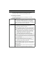
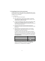
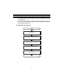
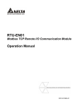
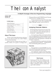
7.1 Installation procedures
START
Install the utility.
Power OFF the personal computer.
Install the CC-Link IE Controller Network
board to the personal computer.
Power ON the personal computer.
Install the driver.
END
22
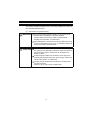
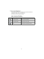
7.2 Icons to be Registered
After installing the software packages, the icons shown below are
registered in Start menu on the Windows .
Click the each icon and start the utility.
[Start] - [Program] - [MELSEC] or
[Start] - [All Programs] - [MELSEC]
Icon
Utility name
Description
CC IE Control utility
Starts CC IE Control utility.
Device Monitor Utility
Starts Device monitor utility.
MELSEC Data Link Function
HELP
Starts HELP for the data link function.
23
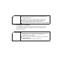
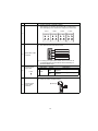
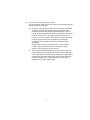
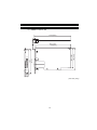
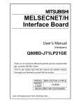
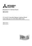
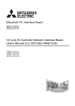
8. EXTERNAL DIMENSIONS
(1) Q80BD-J71GP21-SX
174.5 (6.87)
SD
IN
RD
121
(4.76)
RUN ERR.
107 (4.21)
98.5 (3.88)
181 (7.13)
168 (6.61)
OUT
BD808C
317G51
18.5
(0.73)
(Unit: mm (inch))
24
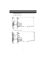
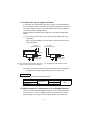
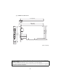
(2) Q80BD-J71GP21S-SX
174.5 (6.87)
181 (7.13)
168 (6.61)
E.PW
RD
121
(4.76)
RUN
ERR.
SD
IN
107 (4.21)
98.5 (3.88)
E.PW
OUT
E.PW
+24VDC
24G
NC
BD808C
317G51
18.5
(0.73)
(Unit: mm (inch))
Microsoft and Windows are registered trademarks of Microsoft Corporation in the United States
and other countries.
Ethernet is a registered trademark of Xerox Corporation in the United States.
Other company names and product names used in this document are trademarks or registered
trademarks of respective companies.
25
Warranty
Please confirm the following product warranty details before using this product.
1. Gratis Warranty Term and Gratis Warranty Range
If any faults or defects (hereinafter "Failure") found to be the responsibility of
Mitsubishi occurs during use of the product within the gratis warranty term,
the product shall be repaired at no cost via the sales representative or
Mitsubishi Service Company.
However, if repairs are required onsite at domestic or overseas location,
expenses to send an engineer will be solely at the customer's discretion.
Mitsubishi shall not be held responsible for any re-commissioning,
maintenance, or testing on-site that involves replacement of the failed
module.
[Gratis Warranty Term]
The gratis warranty term of the product shall be for one year after the date of
purchase or delivery to a designated place.
Note that after manufacture and shipment from Mitsubishi, the maximum
distribution period shall be six (6) months, and the longest gratis warranty
term after manufacturing shall be eighteen (18) months. The gratis warranty
term of repair parts shall not exceed the gratis warranty term before repairs.
[Gratis Warranty Range]
(1) The range shall be limited to normal use within the usage state, usage
methods and usage environment, etc., which follow the conditions and
precautions, etc., given in the instruction manual, user's manual and
caution labels on the product.
(2)Even within the gratis warranty term, repairs shall be charged for in the
following cases.
1. Failure occurring from inappropriate storage or handling, carelessness
or negligence by the user. Failure caused by the user's hardware or
software design.
2. Failure caused by unapproved modifications, etc., to the product by
the user.
3. When the Mitsubishi product is assembled into a user's device, Failure
that could have been avoided if functions or structures, judged as
necessary in the legal safety measures the user's device is subject to
or as necessary by industry standards, had been provided.
4. Failure that could have been avoided if consumable parts (battery,
backlight, fuse, etc.) designated in the instruction manual had been
correctly serviced or replaced.
5. Failure caused by external irresistible forces such as fires or abnormal
voltages, and Failure caused by force majeure such as earthquakes,
lightning, wind and water damage.
6. Failure caused by reasons unpredictable by scientific technology
standards at time of shipment from Mitsubishi.
7. Any other failure found not to be the responsibility of Mitsubishi or that
admitted not to be so by the user.
26
2. Onerous repair term after discontinuation of production
(1) Mitsubishi shall accept onerous product repairs for seven (7) years after
production of the product is discontinued.
Discontinuation of production shall be notified with Mitsubishi Technical
Bulletins, etc.
(2) Product supply (including repair parts) is not available after production is
discontinued.
3. Overseas service
Overseas, repairs shall be accepted by Mitsubishi's local overseas FA
Center. Note that the repair conditions at each FA Center may differ.
4. Exclusion of loss in opportunity and secondary loss from warranty
liability
Regardless of the gratis warranty term, Mitsubishi shall not be liable for
compensation of damages caused by any cause found not to be the
responsibility of Mitsubishi, loss in opportunity, lost profits incurred to the
user by Failures of Mitsubishi products, special damages and secondary
damages whether foreseeable or not , compensation for accidents, and
compensation for damages to products other than Mitsubishi products,
replacement by the user, maintenance of on-site equipment, start-up test run
and other tasks.
5. Changes in product specifications
The specifications given in the catalogs, manuals or technical documents
are subject to change without prior notice.
27
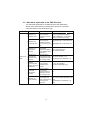
Country/Region Sales office/Tel
Country/Region Sales office/Tel
U.S.A
Mitsubishi Electric Automation Inc.
500 Corporate Woods Parkway Vernon
Hills, IL 60061, U.S.A.
Tel : +1-847-478-2100
Hong Kong Mitsubishi Electric Automation
(Hong Kong) Ltd.
10th Floor, Manulife Tower, 169 Electric
Road, North Point, Hong Kong
Tel : +852-2887-8870
Brazil
MELCO-TEC Rep. Com.e Assessoria
Tecnica Ltda.
Rua Correia Dias, 184,
Edificio Paraiso Trade Center-8 andar
Paraiso, Sao Paulo, SP Brazil
Tel : +55-11-5908-8331
Germany
Mitsubishi Electric Europe B.V. German
Branch
Gothaer Strasse 8 D-40880 Ratingen,
GERMANY
Tel : +49-2102-486-0
U.K
Mitsubishi Electric Europe B.V. UK
Branch
Travellers Lane, Hatfield, Hertfordshire.,
AL10 8XB, U.K.
Tel : +44-1707-276100
Italy
Mitsubishi Electric Europe B.V. Italian
Branch
Centro Dir. Colleoni, Pal. Perseo-Ingr.2
Via Paracelso 12, I-20041 Agrate Brianza.,
Milano, Italy
Tel : +39-039-60531
Spain
France
Mitsubishi Electric Europe B.V. Spanish
Branch
Carretera de Rubi 76-80,
E-08190 Sant Cugat del Valles,
Barcelona, Spain
Tel : +34-93-565-3131
Mitsubishi Electric Europe B.V. French
Branch
25, Boulevard des Bouvets, F-92741
Nanterre Cedex, France
TEL: +33-1-5568-5568
South Africa Circuit Breaker Industries Ltd.
Private Bag 2016, ZA-1600 Isando,
South Africa
Tel : +27-11-928-2000
China
Mitsubishi Electric Automation
(China) Ltd.
4/F Zhi Fu Plazz, No.80 Xin Chang Road,
Shanghai 200003, China
Tel : +86-21-6120-0808
Taiwan
Setsuyo Enterprise Co., Ltd.
6F No.105 Wu-Kung 3rd.Rd, Wu-Ku
Hsiang, Taipei Hsine, Taiwan
Tel : +886-2-2299-2499
Korea
Mitsubishi Electric Automation Korea Co., Ltd.
1480-6, Gayang-dong, Gangseo-ku
Seoul 157-200, Korea
Tel : +82-2-3660-9552
Singapore
Mitsubishi Electric Asia Pte, Ltd.
307 Alexandra Road #05-01/02, Mitsubishi
Electric Building, Singapore 159943
Tel : +65-6470-2460
Thailand
Mitsubishi Electric Automation (Thailand)
Co., Ltd.
Bang-Chan Industrial Estate No.111
Moo 4, Serithai Rd, T.Kannayao,
A.Kannayao, Bangkok 10230 Thailand
Tel : +66-2-517-1326
Indonesia
P.T. Autoteknindo Sumber Makmur
Muara Karang Selatan, Block A/Utara
No.1 Kav. No.11 Kawasan Industri
Pergudangan Jakarta - Utara 14440,
P.O.Box 5045 Jakarta, 11050 Indonesia
Tel : +62-21-6630833
India
Messung Systems Pvt, Ltd.
Electronic Sadan NO:III Unit No15,
M.I.D.C Bhosari, Pune-411026, India
Tel : +91-20-2712-3130
Australia
Mitsubishi Electric Australia Pty. Ltd.
348 Victoria Road, Rydalmere,
N.S.W 2116, Australia
Tel : +61-2-9684-7777
HEAD OFFICE : TOKYO BUILDING, 2-7-3 MARUNOUCHI, CHIYODA-KU, TOKYO 100-8310, JAPAN
NAGOYA WORKS : 1-14, YADA-MINAMI 5-CHOME, HIGASHI-KU, NAGOYA, JAPAN
When exported from Japan, this manual does not require application to the Ministry
of Economy, Trade and Industry for service transaction permission.
Specifications subject to change without notice.