1
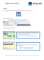
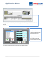
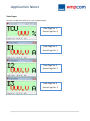
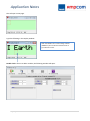
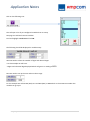
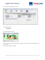
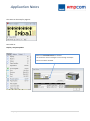
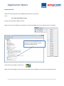
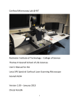
Application Notes
AMPCOM DMPU-PSHMI Configuration Software
DEPARTMENT: Motor Control & Drives
ACCESS LEVEL: External
PREPARED BY: Dane Bosquet
DATE CREATED: 17/12/12
SUPPLIER: NHP & Carlo Gavazzi
VERSION: 1.0
Introduction:
The purpose of this application note is to give step by step instructions to configure the DMPU-HMI interface
for the NHP AMPCOM system. The DMPU-Human Machine Interface module can display real time data from
the AMPCOM system, display current alarms and has 4 configurable buttons.
DMPU-HMI
Connection:
You will require a physical connection from the AMPCOM main module (DMPU-MBT or DMPU-PRB) to the
DMPU-HMI, RS-485 connection from your computer with DMPU-PSHMI software to the DMPU-HMI. See
next page for physical connections.
RS-485 to USB converter
(DMPU-PC)
2-wire serial
Digital HMI Display
Main Module
DMPU-HMI
DMPU-MBT or DMPU-PRB
Computer with DMPU-PSHMI
software installed
Modbus/TCP or Profibus protocols can NOT be used for configuration of the DMPU-HMI
Connection Diagrams:
Application Notes
The DMPU-HMI has the following connections on the back of the unit.
Communication ports
Power Circuit
There are two options for connecting the DMPU-HMI
1. Connections as above, COM2 connected directly to the main module and COM0 directly to the
serial to USB converter. You may want to choose this option if the rear of the DMPU-HMI is easily
accessible.
COM2
+
B+
-
A-
COM0
+
R+
-
RRS-485 to USB converter
2. COM2 and COM0 can be wired in parallel directly to the DMPU main module, the programming
port from the main module is then connected to the PC via RS-485 to USB converter (DMPU-PC).
This option is suitable when the programming port is installed on the front of the panel so both
DMPU-HMI and main module can be programed using the same connection.
Panel
COM2
+
B+
-
A-
COM0
+
RS-485 to USB
converter
Programing Port (DMPU-CPC)
2|P a g e
Application Notes
Software:
Once the DMPU-PSHMI software has been installed click on the icon on your desktop.
When the program opens click:
File > Upload Configuration File > Basic configuration.gav
The following windows will appear:
The display window shows all the pages that can be viewed on the HMI
screen, all pages can support any text as well as variables that are read
from the main module. E.g. TCU and Amps (I)
The text in red is where the variables are displayed when the HMI is
online.
The alarms page configures which alarms will be displayed on the screen
when they occur.
Text can also be added but only on the bottom line, the screen will be
displayed as follow:
T234 A334 < top line alarm code not editable
TCU TRIP
< bottom line text added by user
3|P a g e
Application Notes
The button page is used to configure macros or functions for each button
depending on the page selected.
Also described as button A, B, C, D from top to bottom.
The Macros that can be set are:
MAC_NULL: No command
MAC_PAGE: Go to a page no.
MAC_WRITE: Write a value to input registers e.g. Virtual inputs
MAC_TOGGLE: Toggles any input registers e.g. Virtual input
Add and edit variables:
Click on:
Display > Project Options
Or click on the
4|P a g e
icon on the task plane.
Application Notes
The project options screen allows you to add a project name and change communication baud rates.
Click on:
> Var. Externals
The Set External Variables window
allows you to edit, read and write
variables form the DMPU-HMI.
In the Basic configuration.gav file
these variables are pre-set.
Address and Dimensions for each
tag can be found in the DMPU
User Manual.
Any variables not being used
should be deleted from this table.
To close this window click on OK and OK on the Project Options window.
5|P a g e
Application Notes
View Pages:
The Basic configuration.gav file has 7 pre-configured pages:
View Page No. 1
Actual Page No. 0
View Page No. 2
Actual Page No. 1
View Page No. 3
Actual Page No. 2
View Page No. 4
Actual Page No. 3
6|P a g e
Application Notes
View Page No. 5
Actual Page No. 4
View Page No. 6
Actual Page No. 5
View Page No. 7
Actual Page No. 6
To scroll through the pages click on the Display window and use the arrows on the above task planes:
The single right and left arrows will scroll through each individual pages.
The double arrows will skip to the first and last page.
7|P a g e
Application Notes
Add Pages:
Use the following icons to Insert, Append and Delete page icons.
Insert Page:
Append Page:
Delete Page:
Add a page before the
current selected page.
Add a page after the current
selected page.
Delete/remove current page
Go to page:
And click on:
> Append page
8|P a g e
Application Notes
This will open a new page:
Type the following in the Display window:
With the addition of an earth leakage module
(DMPU-EL) we can add and view the level of
ground fault current.
Double click a section to add a variable, the following window will open:
9|P a g e
Application Notes
Click on the following icon:
This will open a list of pre-configured variables that are setup.
See page 5 to add and remove variables.
Find and highlight I earth 64 and click OK.
The following should be displayed in variable setup:
We now need to select the number of digits and decimal digits.
For this example we will have:
2 digits and 1 decimal digit displayed which will give us a reading of 00.0
Next we need to set up the max and min value range:
For this example we will set Min (DEC) to 0 and Max (DEC) to 9999 which is the maximum number this
variable can go up to.
10 | P a g e
Application Notes
Your variable setup page should look like this:
Once complete click on:
> Save [ENTER]
The display should look like this:
You can also add a character after the value e.g. A (amps) or V (volts). In this case we will add character A
after the value.
You have now completed a new page.
11 | P a g e
Application Notes
Auto Link:
Auto link is a feature where commands can be automatically set and assigned buttons to scroll through
each page.
For example when the unit is powered we would like the up and down arrows (buttons B and C) to scroll
through each page and when we get to the last page to loop back to the first page or vice versa.
The auto link function needs to be executed every time a page is added or removed
12 | P a g e
Application Notes
To achieve this we will use the auto link function in the Project menu.
Click on:
Project > Auto Link
The following page will show:
Initial Page is the first page in the loop we will set this to page 0.
Final Page is the last page in the loop, this case it will be page 7.
Incremental Page Key will be the up arrow key which is key B
Decremental Page Key will be the down arrow key which is key C.
Link Int.Page with Final Page will allow the last page to loop back to the first page.
Once all the values have been entered click on Execute then Close
13 | P a g e
Application Notes
Alarms:
To show an alarm status on the DMPU-HMI when the alarm occurs we need to enable it through the
alarms window.
Click on the alarms window and use the following buttons on the task plane:
This will allow you to scroll through all 32 pages, each page corresponds to a virtual alarms set in the
DMPU main module configuration.
A typical configuration may look like this:
14 | P a g e
Application Notes
For example we want an alarm to appear for thermal image (TCU) and current imbalance (IMB%).
From the above configuration we can see that:
Thermal image 49 is VA#9 (Virtual Alarm 9)
IMB% or Current Imbalance is VA#14 (Virtual Alarm 14)
Select the alarm window and using the
icon scroll through to page 9
You can type in an alarm description on the bottom line only as the top line is reserved for alarm codes.
Reserved Line
Description
To enable the alarm the
View Alarm box needs to
be checked
15 | P a g e
Page No.
Application Notes
The same can be setup for page 14:
Now Click on:
Display > Project Options
Make sure Immediate Alarms is checked.
This allows the alarms messages to scroll through if multiple
alarms have been activated.
16 | P a g e
Application Notes
Compile and send:
Before we send the project to the DMPU-HMI we need to save the file.
Go to:
File > Save project whit a name
Save the new file under a different name.
Make sure the correct COM port is selected, in this case the DMPU-PC serial to USB converter is on COM 7.
You can check this by going to Device
Manager through Windows Control
Panel and clicking on Ports.
l
Now click on the compile and send icon
When you are prompted to connect the system make sure the DMPU-PC is connected as previously shown.
17 | P a g e