1
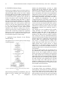
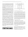
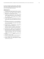
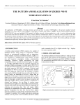
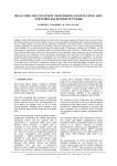
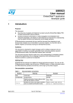
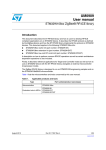
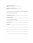
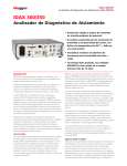
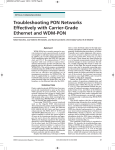
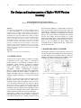
96
IJCSNS International Journal of Computer Science and Network Security, VOL.15 No.1, January 2015
The Design and Implementation of ZigBee-Wi-Fi Wireless
Gateway
Rakesh Manukonda and Suresh Nakkala
M.Tech. in VLSI&ES, MLEC, Singarayakonda, JNTU, Kakinada.
Abstract
The application of WSN/ZigBee is growing popularity and how
to connect WSN/ZigBee to the present standard network
seamlessly is an issue what is worth studying. In this paper, it
designs and realizes a ZigBee—Wi-Fi wireless gateway based on
STM32W108 RF chip and embedded Wi-Fi module. In ZigBee
network, wireless gateway as a sink, it receives data from sensor
nodes and interacts with them. In WLAN, wireless gateway
communicates with PC or network servers by means of AP. Both
the hardware scheme and software scheme of the wireless
gateway are introduced. Then the performance of the wireless
gateway is tested, and the result shows that it can be used for
general purposes and the performance is stable. The wireless
gateway can realize communication effectively between ZigBee
network and WLAN.
Keywords
ZigBee; Wi-Fi; wireless gateway; STM32W108
1. INTRODUCTION
A wireless sensor network (WSN) [1] consists of a number
of distributed devices using sensors to cooperatively
monitor physical or environmental conditions, such as
temperature, sound, vibration or pressure at different
locations. ZigBee [2] is a new IEEE802.15.4 standardsbased, short distance, low-data-rate and low-power
consumption
wireless
communication
technology.
Moreover, ZigBee specification has better compatibility
between versions from earliest ZigBee 1.0, ZigBee 1.1 to
ZigBee 2007/PRO. With the constantly improving and
maturing of ZigBee technology, it is widely used in WSN
[3] [4].
Wi-Fi [5] is a most successful wireless local area network
(WLAN) system that builds upon the IEEE 802.11
standards. With the rapid development of Wi-Fi in recent
years, infrastructure facilities have been improved. What’s
more, the coverage of wireless access points (AP) has
already been very wide and the price is cheap. Usually, the
bandwidth of WLAN is higher than the bandwidth of other
types of internet connection such as ADSL, GPRS and 3G
and the transmission delay of WLAN is less than theirs.
In this paper, a small in size, low-power, low-price and
lightweight ZigBee–Wi-Fi wireless gateway is introduced.
It contains two functions. For one thing, in wireless sensor
Manuscript received January 5, 2015
Manuscript revised January 20, 2015
network based on ZigBee (it is called ZigBee network for
short), terminal sensor nodes and route sensor nodes are
responsible for collecting and processing data. They will
employ ZigBee technology to communicate with wireless
gateway. The wireless gateway encapsulates the data that
received from ZigBee network according to a certain
format and transmits them to Wi-Fi module. For another,
Wi-Fi module sends data to monitoring software on PC by
means of AP. In addition, the Wi-Fi module sends
commands from PC to ZigBee network. Fig. 1 displays the
system operation model.
2. HARDWARE DESIGN SCHEME
The hardware platform of wireless gateway is made up of
two parts: the RF chip STM32W108 [6] that integrates a
2.4 GHz, IEEE 802.15.4-compliant transceiver and 32-bit
ARM® CortexTM-M3 microprocessor and EMW-380 WiFi module. The structure is demonstrated in Fig. 2.
Figure 1. The communication model between ZigBee network and
WLAN.
Figure 2. The hardware structure of wireless gateway.
IJCSNS International Journal of Computer Science and Network Security, VOL.15 No.1, January 2015
A. STM32W108
STM32W108 is a fully integrated System-on-Chip (SoC)
launched by STMicroelectronics recently. It has 128
Kbytes of embedded Flash memory, 8Kbytes of integrated
RAM memory for data and program storage and
peripherals (like USART, SPI, TWI, ADC, generalpurpose timers and 24 GPIOs) of use to designers of
ZigBee -based systems. The processor can be operated at
12 MHz or 24 MHz when using the crystal oscillator, or at
6 MHz or 12 MHz when using the integrated high
frequency RC oscillator.
The difference between STM32W108 and other 2.4GHz
SoC chips are as follows: (1) STM32W108 adopts 32-bit
ARM® CortexTM-M3 processor, which can improve
processing performance based on lower power
consumption.
(2) It supports for external power amplifier and the output
power is up to +7dBm. (3) Different types of
STM32W108 solidify different protocol stacks such as
802.15.4 MAC [7], EmberZNet ZigBee PRO [8] and
ZigBee RF4CE [9]. Users do not have to understand the
network protocol development and they can directly
exploit wireless networking products that comply with the
relevant standards, which can greatly simplify the
development of the technical complexity products and
shorten time to market. In this paper, the type of
STM32W108 used integrates EmberZNet ZigBee PRO
Stack. Meanwhile, STM32W108 is responsible for
wireless communication between wireless gateway and
ZigBee sensor nodes.
B. EMW-380 Wi-Fi Module
The wireless gateway adopts EMW-380 Wi-Fi module
[10] to realize the WLAN capabilities. It is an embedded
Wi-Fi (802.11b/g) applicable module. The hardware is
composed of ARM processor and Wi-Fi RF chip. The
software integrates some network protocols such as Wi-Fi,
TCP/IP, UDP, and DHCP. The module provides an
SPI/UART interface to connect with MCU. A simple API
command set is provided to implement link layer data
services based on 802.3 frame formats. The module
supports AP and Ad-Hoc, RF channel automatic choice
and WEP encryption, which is suitable for small system
with standard Wi-Fi access.
3. SOFTWARE DESIGN SCHEME
The software architecture of the wireless gateway includes
system control, software design of EMW -380 Wi-Fi
module, software design of STM32W108 and wireless
gateway application layer protocol. The software
architecture is shown in Fig. 3. System control regulates
97
hardware and application layer protocol of the wireless
gateway.
Figure 3. The software architecture of wireless gateway.
TABLE I. EMSP PROTOCOL FORMAT
Protocol head
Data field
head
data
command length result
data
checksum
checksum
A. EMW-380 Wi-Fi Module Software Design
EMW-380
Wi-Fi
module
communicates
with
STM32W108 through UART and EMSP protocol. And the
EMSP protocol has nothing to do with the physical
connection. The module has two operative modes:
configuration mode and data transparent transmission
mode. In the configuration mode, all the work is controlled
by EMSP command. In the data transparent transmission
mode, module encapsulates the received data into
TCP/UDP packets and sends them to remote end.
Furthermore, it can send the TCP/UDP packets that come
from remote end to STM32W108. The data packet format
of EMSP protocol is shown in Table 1. It contains a
protocol head (8 Bytes) and data field (maximum is 256
Bytes).
As shown in Table 1, all the request and response
commands are checked to ensure the integrality and
reliability. The EMSP protocol consists of 12 commands
to implement module control, network control and network
communication.
They
are
EMSP_CMD_RESET,
EMSP_CMD_GET_CONFIG,
EMSP_CMD_SET_CONFIG,
EMSP_CMD_GET_STATUS,
EMSP_CMD_RECV_DATA,
EMSP_CMD_SEND_DATA, EMSP_CMD_SCAN_AP,
EMSP_CMD_GET_MF_INFO,
EMSP_CMD_GET_RF_POWER,
EMSP_CMD_GET_VER, EMSP_CMD_START and
EMSP_CMD_SET_RF_POWER.
From the angle of implementation, different commands of
EMSP protocol have different response time.
98
IJCSNS International Journal of Computer Science and Network Security, VOL.15 No.1, January 2015
B. STM32W108 Software Design
From the point of ZigBee network, the wireless gateway is
a sink and gathers all kinds of data from sensor nodes. The
EmberZNet ZigBee PRO provides users with a standard
networking API based on the ZigBee specification across
the STM32W108 platforms. Users can just learn how to
use API functions on the application layer, and then can
develop own projects. Due to increasing flexibility and
reliability of EmberZNet ZigBee PRO Stack, it supports
three types of mesh network topologies [11]: star network,
full mesh network and hybrid mesh network. Aiming at the
application design of the wireless gateway, hybrid mesh
network is used. The stack mentioned above allows users
to create own wireless personal area network (WPAN)
[12]. The basic functions of stack contain network
organization, route discovery, routing, device discovery,
message relay and security. Under the application layer of
protocol stack is followed by transport layer, application
support layer, network routing and discovery, MAC and
RF abstraction layer. Physical RF and medium access
provide hardware support for software design.
C. Application Layer Protocol of the Wireless
Gateway Design
The application layer of wireless gateway software design
is described in Fig. 4.
EM380C_fast_Init(BAUDRATE) provided by EMSP
protocol API set can configure the interface between
STM32W108 and EMW-380 Wi-Fi module. It will take
about 1-2 seconds to completely initialize the module, and
then it will respond to the request sent by STM32W108.
STM32W108 can query the /INT pin of EMW-380 Wi-Fi
module to determine whether the initialization is complete.
After finishing initialization, /INT changes from high to
low. EM380C_Set_Config(&parms) can set the
configuration parameters of the module. And it will launch
the module when using EM380C_Startup() function. Once
the module has connected to monitoring software on PC as
a client, it will enter into transparent data transfer operative
mode. Then the module can send the data received from
STM32W108 to monitoring software. Besides, the module
will send the commands from monitoring software to
STM32W108.
After finishing the work of EMW-380 Wi-Fi module,
calling emberInit() can complete the initialization of
EmberZNet ZigBee PRO Stack and RF module. The
network initialization is done by emberNetworkInit().
Furthermore, the address table also should be initialized.
After entering into event loop, emberFormAndJoinTick()
function can form network according to the given network
parameters and join in it. And then the permit joining flag
becomes TRUE. The applicationTick() function offers
some services: (1) checking timeout, (2) sending a route
request packet that creates routes from every node in
ZigBee network back to wireless gateway, (3) calling
sinkAdvertise() to send multicast message, (4) detecting
whether it have received data from EMW-380 Wi-Fi, (5)
updating the address table, (6) setting the time permitted to
join in network.
Of course, the wireless gateway plays an important role in
the communication model between ZigBee network and
WLAN. On the side of ZigBee network, the wireless
gateway takes charge of processing data on the application
layer. NWK and MAC layers are managed by EmberZNet
ZigBee PRO Stack while STM32W108 handles with PHY
layer. From the point of view of WLAN, wireless gateway
also deals with data on the application layer and other
layers like TCP/IP, 802.11 MAC and 802.11 PHY are
regulated by EMW-380 Wi-Fi module. There are two
directions of data communication in communication model
between ZigBee network and WLAN.
1) Data from ZigBee network to WLAN
Figure 4. Application layer protocol of the wireless gateway software
design.
When initializing STM32W108, INTERRUPTS_ON() and
halInit() are used to configure clock, open system timer
and
turn
on
interruptions.
In the ZigBee network, after establishing a network by
wireless gateway, sensor nodes join in the network within
the time that wireless gateway permits. When the time
expires, sensor nodes can’t join in the network any more
unless the button is pressed on route sensor nodes and then
the permit joining flag becomes TRUE again. But if the
IJCSNS International Journal of Computer Science and Network Security, VOL.15 No.1, January 2015
sensor node is the terminal node, it can’t allow other nodes
to join in the network through itself. So the size of the
network can be dynamically changed, and the extensibility
of ZigBee network is good. Every node has a unique
NodeID assigned by wireless gateway once join process
has completed. After interacting with wireless gateway as
shown in Fig. 5, sensor nodes begin to send data to
wireless gateway.
SINK_ADVERTISE is sent regularly, and the time interval
can be set by users. And they will record each other’s
MAC address and NodeID in their address tables before
exchanging data. This interaction procedure can ensure
that the data that sensor nodes send to wireless gateway is
correct and integral. When the sensor node is a sleep node,
it will enter into power save mode once it is idle. If the
sleep node misses the SINK_ADVERTISE sent by
wireless gateway, it can send SINK_QUERY message to
wireless gateway asking for SINK_ADVERTISE and then
start to send data to wireless gateway after finishing the
interaction procedure in Fig. 5.
When wireless gateway receives data from ZigBee network,
it will parse data in terms of the type of monitoring data in
application layer. And then it again packages the
monitoring data according to the format in Table 2. The
start fields of data from ZigBee network to WLAN are
0x7E and 0x42 and the end field is 0x7E. The Payload
data contain MSG_ HEADER and MSG_DATA.
MSG_HEADER consists of the length of MSG_DATA,
MAC frame control field, destination PAN identifier,
destination address, data type (data, command, data
response or command response) and the group information
of sensor nodes. MSG_DATA includes NodeID and
monitoring data while monitoring data will vary with
different applications. The check field is CCS checksum,
which is used to judge whether the data are correct.
TCP/IP protocol embedded within EMW-380 Wi-Fi
module encapsulates the data that are from application
layer of wireless gateway. Then in transparent transmission
mode, it sends the encapsulated data to WLAN. The
monitoring software processes the received data and
feedback to the users.
TABLE II. THE FORMAT OF DATA FROM ZIGBEE NETWORK TO
WLAN
Data Packet Format Field
start field MSG_HEADER MSG_DATA check end field
99
Figure 5. The interaction procedure between sensor node and wireless
gateway.
2) Data from WLAN to ZigBee network
The way of transmitting data from WLAN to ZigBee
network is almost the same. The data from the WLAN is
first transmitted to EMW-380 Wi-Fi module. It extracts the
data from the TCP packet, and transmits them to the
application layer of wireless gateway. The application
layer of wireless gateway parses the data according to the
format in Table 2, and hands over the data to EmberZNet
ZigBee PRO Stack. The stack will assemble them to IEEE
802.15.4 frame and send to destination node in ZigBee
network. The process includes the routing of the network,
so that the data sent to the specified node by the WLAN
always reach the destination correctly. Besides, the node is
identified by the NodeID. When the node receives data,
then it handles with them further.
4. PERFORMANCE EVALUATION
In this section, performance evaluation and its result are
discussed. Hardware test environment includes wireless
gateway, TP-LINK TL-WN322G+ 54Mbps wireless USB
network card, PC, several sensor nodes, network sniffer
produced by Mxchip Company and a network protocol
analyzer for UNIX and Windows called Wireshark.
A. Functional Test
Firstly, the function of wireless gateway is tested. As
shown in Fig. 6, the monitoring software on PC is a server
and its IP address is 192.168.4.7. While the IP address of
wireless gateway is 192.168.4.53 and it is a client. While
the Wireshark software can capture the data packet that
wireless gateway sends to monitoring software.
100
IJCSNS International Journal of Computer Science and Network Security, VOL.15 No.1, January 2015
grows, P gets smaller and PLR falls dramatically. So T is
an important influential factor to PLR.
Figure 6. The data are shown by monitoring software.
For example, the data that wireless gateway send to
monitoring software are 7E 42 0C 00 00 2B 00 FF 00 FF
11 00 71 67 00 00 00 00 FF FF FF FF FF FF CD 00 00 00
58 A7 7E. Among the 31 Bytes data, CD and 00 are just
light intensity value 0x00CD measured by sensor node. Its
NodeID is 26481. Comparing 0x00CD with the data of
ZigBee network layer packet that captured by network
sniffer, the result is that they are same. The decimal
number of 0x00CD is 205 and it can be seen from Fig. 6.
Moreover, users can observe and analyze all the data that
measured by sensor nodes, as shown in Fig. 6.
2) Test scenario 2
The test scenario is similar to test scenario 1, but the T is
100ms and changes in L. The four curves in Fig. 8
respectively show the changes of PLR when the L is 82
Bytes, 62 Bytes, 42 Bytes and 22 Bytes. In the above four
cases, ten tests are also done respectively. And the PLR
also is an average value. As shown in the Fig. 8, when L
grows bigger, PLR increases accordingly. Under the
condition that N and T are invariable and L becomes
bigger, the time of cost in sending a data packet is
increasing. And the time that data packet occupies the
channel will corresponding grow longer. Therefore, when
P grows, it causes PLR upwards. The reason four curves in
Fig. 8 are close to each other is because the time of
sending a data packet successfully is nearly unchanged
although L changes . The time mentioned above includes
the propagation delay and transmission delay. When L
varies, PLR will change, but the changes are not very
obvious.
B. Performance Test
1) Test scenario 1
Sensor nodes distribute randomly around the wireless
gateway. The rule is that each node sends only 1000 data
packets to wireless gateway and then stop. The length of
each packet is 82 Bytes, which is the maximum packet
load length that users used on application layer. As Fig. 7
described, x-axis denotes the number of nodes in ZigBee
network and y-axis represents the average packet loss rate
(PLR) of wireless gateway. The four curves respectively
show the change of PLR when the time interval of sending
data is 80ms (millisecond), 100ms, 120ms or 200ms. In the
above four cases, ten tests are done respectively. So the
PLR is an average value of the ten tests. As the time
interval increases, PLR drops. If the time interval of
sending a data packet is 1 second and there are 8 sensor
nodes in the ZigBee network, the PLR of wireless gateway
drops to 0%.
The reason why PLR varies with the time interval of
sending data packet is that PLR depends on three factors:
the number of sensor nodes (N) in ZigBee network, the
time interval of sending data packet (T) and the length of
data packet (L). When N and L remain the same and T gets
smaller, the number of packet sent to the air per second
increases, and then the collision probability (P) raises
when sending data packet. Although there is data
retransmission mechanism in EmberZNet ZigBee RPO
Stack and retransmission number is up to 3, the
consecutive collision probability that is P3 would be
substantially increased. Therefore, when time interval
Figure 7. Packet loss rate changes when different time interval used.
Figure 8. Packet loss rate changes when the length of packet varies.
5. CONCLUSION
In this paper, the ZigBee—Wi-Fi wireless gateway based
on STM32W108 RF chip and EMW-380 Wi-Fi module
can connect the ZigBee network to standard network
seamlessly. From the result of performance test we can see
that the performance and stability of wireless gateway suits
the usual target of WSN application, which is low real time
demand, small amount of data transmission and low
bandwidth. As applications expansion of WSN, further
research can focus on:
IJCSNS International Journal of Computer Science and Network Security, VOL.15 No.1, January 2015
the low power design of wireless gateway, using wireless
gateway ID to identify different deployment environments
and adopting embedded Web Server technology enables
users to visit different WSNs information.
REFERENCES
[1] David Culler, Deborab Esrtin, Mani Sivastava, “Overview
of sensor networks”, IEEE Computer Society, August 2004.
[2] ZigBee Alliance, Latest ZigBee specification including the
PRO feature set. http://www.zigbee.org, 2005.
[3] Hong-jiang He, Zhu-qiang Yue, and Xiao-jie Wang,
“Design and realization of wireless sensor network gateway
based on ZigBee and GPRS,” Int. Conf. Inf. Comput. Sci.,
ICIC. Manchester, United kingdom: IEEE Computer
Society, 2009, pp.196-199.
[4] Cai Hao, Feng Renjian, and Wan Jiangwen, Wireless sensor
network gateway with multi-communication methods [J].
Chinese Journal of Sensor and Actuators. 2008, 21(1):169172.
[5] Ali.Khidir.M, Owens.Thomas J, “Access mechanisms in
Wi-Fi networks state of art, flaws and proposed solutions”,
ICT: Int. Conf. Telecommun. Doha, Qatar: IEEE Computer
Society, 2010, pp.280-287.
[6] STMicroelectronics, STM32W108HB STM32W108CB
DataSheet. http://www.st.com/mcu, 2010.
[7] Ghasemi Abdorasoul, Razavizadeh S. Mohammad, “A
simple MAC protocol for cognitive wireless networks”,
IEICE Trans Commun. vol E92-B, pp. 3693-3700, 2009.
[8] STMicroelectronics, UM0923 User manual EmberZNet™
application developer guide. http://www.st.com/mcu, 2010.
[9] Shon.Taeshik and Park Yongsuk, “Implementation of
RF4CE-Based Wireless Auto Configuration Architecture for
Ubiquitous Smart Home”, CISIS - Int. Conf. Complex,
Intelligent Softw. Intensive Sys. Krakow, Poland: IEEE
Computer Society, 2010, pp.779-783.
[10] Mixchip,
EMW-380_RM01040141.pdf.
http://www.mxchip.com, 2009.
[11] I.Akyildiz, X. Wang, W. Wang, “Wireless mesh networks: a
survey”, Computer Networks 47(4), 2005, pp.445-487.
[12] Xu Xiaotao and Wu Yanlin, Technology and Application of
Wireless Personal Area Network (WPAN) . Beijing:
Posts&Telecom press, 2009.
101