1
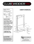
¨
ORDERING REPLACEMENT PARTS
If you encounter any difficulties or problems with this product, contact the ICON Fitness Lifestyle Ltd. office, or
write:
ICON Health & Fitness Ltd.
Unit 4
Revie Road Industrial Estate
Revie Road
Leeds
LS11 8JG
Model No. WEEVBE70200
Serial No.
Tel: Country Code: 0345-089009
Fax: 0113-2411120
The serial number can be found in the
location shown below. Write the serial
number in the space above.
USER'S MANUAL
To help us assist you, please be prepared to give the following information:
¥ The MODEL NUMBER of the product (WEEVBE70200)
¥ The NAME of the product (WEIDER¨ PRO 120 weight bench)
¥ The SERIAL NUMBER of the product (see the front cover of this manual)
Serial Number Decal (under bench)
¥ The KEY NUMBER and DESCRIPTION of the desired part(s) (see page 7 of this manual).
QUESTIONS?
As a manufacturer, we are
committed to providing
complete customer satisfaction.
If you have questions, or if
there are missing parts, we will
guarantee complete satisfaction
through our Customer Service
Department.
Please CALL:
0345-089009
Or WRITE:
ICON Health & Fitness Ltd.
Unit 4
Revie Road Industrial Estate
Revie Road
Leeds
LS11 8JG
CAUTION
Read all precautions and instructions in this manual before
using this equipment. Save this
manual for future reference.
Part No. 172312 R1200A Printed in China © 2000 WEIDER is a registered trademark of ICON Health & Fitness, Inc.
Visit our website at
www.weiderfitness.com
TABLE OF CONTENTS
IMPORTANT PRECAUTIONS . . . . . . . . . . . . . . . . . . . . . . . . . . . . . . . . . . . . . . . . . . . . . . . . . . . . . . . . . . . . . 2
BEFORE YOU BEGIN . . . . . . . . . . . . . . . . . . . . . . . . . . . . . . . . . . . . . . . . . . . . . . . . . . . . . . . . . . . . . . . . . . . 3
ASSEMBLY . . . . . . . . . . . . . . . . . . . . . . . . . . . . . . . . . . . . . . . . . . . . . . . . . . . . . . . . . . . . . . . . . . . . . . . . . . . 4
ADJUSTING THE WEIGHT BENCH. . . . . . . . . . . . . . . . . . . . . . . . . . . . . . . . . . . . . . . . . . . . . . . . . . . . . . . . . 6
PART LIST. . . . . . . . . . . . . . . . . . . . . . . . . . . . . . . . . . . . . . . . . . . . . . . . . . . . . . . . . . . . . . . . . . . . . . . . . . . . 7
EXPLODED DRAWING . . . . . . . . . . . . . . . . . . . . . . . . . . . . . . . . . . . . . . . . . . . . . . . . . . . . . . . . . . . . . . . . . . 7
ORDERING REPLACEMENT PARTS. . . . . . . . . . . . . . . . . . . . . . . . . . . . . . . . . . . . . . . . . . . . . . . . Back Cover
PART LIST and
EXPLODED DRAWINGÑModel No. WEEVBE70200
Key
No. Qty.
1
2
3
4
5
6
7
8
9
IMPORTANT PRECAUTIONS
WARNING:
1
1
1
2
2
4
4
1
4
Key
No. Qty.
Description
Frame
Pivot Leg
Adjustment Leg
M6 x 50mm Screw
M6 x 16mm Screw
Foam Pad
3/4Ó Round Inner Cap
38mm x 50mm Inner Cap
50mm Round Outer Cap
10
11
12
13
14
15
16
#
2
2
1
1
1
1
1
1
R1200A
Description
Pad Tube
Lock Pin
Bench
M10 Nylon Locknut
M10 x 70mm Bolt
ÒLÓ Pin
38mm x 38mm Inner Cap
UserÕs Manual
To reduce the risk of serious injury, read the following important precautions
before using the weight bench.
10. It is the responsibility of the owner to ensure
that all users of the weight bench are adequately informed of all precautions.
1. Read all instructions in this manual before
using the weight bench.
2. Use the weight bench only as described in
this manual.
12
11. The decals shown below have been placed
on the weight bench. If the decals are missing or illegible, please call our Customer
Service Department at 0345-089009 to order a
free replacement decal. Apply the replacement decal in the location shown.
3. Use the weight bench only on a level surface.
Cover the floor beneath the weight bench for
protection.
1
4. Inspect and tighten all parts regularly.
Replace any worn parts immediately.
11
5. Keep children under the age of 12 and pets
away from the weight bench at all times.
Keep hands and
fingers clear of
this area.
6. Always wear athletic shoes for foot protection whilst exercising.
Note: The decals are
shown at 65% of
actual size.
4
8
6
7
13
7. The weight bench does not include weights.
The weight bench is designed to support a
maximum of 300 pounds (135 kg), including
the user and weights.
16
5
10
! WARNING
¥ Misuse of this
product may result in
serious injury.
8. When using the weight bench, make sure
that the lock pins are fully inserted and are
turned to the locked position.
¥ Read userÕs manual
and follow all warnings
and operating instructions prior to use.
2
15
9
6
¥ Do not allow children
on or around machine.
¥ Replace label if
damaged, illegible,
or removed.
9. If you feel pain or dizziness at any time
whilst exercising, stop immediately and
begin cooling down.
7
14
9
9
3
WARNING:
Before beginning this or any exercise program, consult your physician. This
is especially important for persons over the age of 35 or persons with pre-existing health problems.
Read all instructions before using. ICON assumes no responsibility for personal injury or property
damage sustained by or through the use of this product.
2
9
Note: Ò#Ó indicates a non-illustrated part. Specifications are subject to change without notice. See the back cover
of this manual for information about ordering replacement parts.
7
ADJUSTING THE WEIGHT BENCH
BEFORE YOU BEGIN
The weight bench is designed to be used with your own weights (not included). The steps below explain how the
weight bench can be adjusted. Refer to the accompanying exercise poster for exercise information.
Thank you for selecting the WEIDER¨ PRO 120 weight
bench. The PRO 120 weight bench is designed to be
used with your own weights (not included) to develop
several muscle groups. Whether your goal is a shapely figure, dramatic muscle size and strength, or a
healthier cardiovascular system, the PRO 120 weight
bench will help you to achieve the specific results you
want.
Inspect and tighten all parts each time you use the weight bench. Replace any worn parts immediately. The
weight bench can be cleaned with a damp cloth and a mild, non-abrasive detergent. Do not use solvents.
ADJUSTING THE PIVOT LEG
1
To change the position of the Pivot Leg (2), remove the
ÒLÓ Pin (15). Align the other set of holes in the Pivot Leg
and the Frame (1). Re-insert the ÒLÓ Pin.
tions, please call our Customer Service Department.
To help us assist you, please note the product model
number and serial number before calling. The model
number is WEEVBE70200. The serial number can be
found on a decal attached to the weight bench (see
the front cover of this manual).
Before reading further, please review the drawing
below and familiarise yourself with the parts that are
labelled.
For your benefit, read this manual carefully before
using the weight bench. If you have additional ques-
15
Backrest
2
Foam Pads
ADJUSTING THE LEVEL OF THE BENCH
To change the level of the Bench (12), remove both
Lock Pins (11) from the Frame (1) and Adjustment Leg
(3). Align the set of holes in the Frame with another set
of holes in the Adjustment Leg. Re-insert the Lock Pins.
Always use both Lock Pins.
12
Lock Pins
Pivot Leg
1
11
3
Foam Pads
Adjustment Leg
6
3
1. Before beginning assembly, be sure that you
have read and understand the information on
the previous page.
ASSEMBLY
Before beginning assembly, carefully read the
following information and instructions:
¥ Tighten all parts as you assemble them, unless
instructed to do otherwise.
¥ Place all parts in a cleared area and remove the
packing materials; do not dispose of the packing
materials until assembly is completed.
¥ During assembly, make sure that all parts are oriented as shown in the drawings.
THE FOLLOWING TOOLS (NOT INCLUDED)
ARE REQUIRED FOR ASSEMBLY:
¥ Read each assembly step before you begin.
¥ For help identifying the small parts used in
assembly, use the part identification chart
below. The number in parenthesis below each
part refers to the key number of the part. The
second number refers to the quantity needed for
assembly. Note: Some small parts may have
been pre-attached for shipping. If a part is not
in the parts bag, check to see if it has been
pre-attached.
1
8
Align the indicated holes in the Frame (1) and the
Adjustment Leg (3). Attach the Adjustment Leg to
the Frame with two Lock Pins (11).
3
Align these
Holes
Press the 38mm x 38mm Inner Cap (16) into the
end of the Frame (1). Press two 50mm Round
Outer Caps (9) onto the Adjustment Leg (3). Press
the 38mm x 50mm Inner Cap (8) into the Adjustment
Leg.
11
1
16
9
¥ Two adjustable spanners
¥ One Phillips screwdriver
Assembly will be more convenient if you have the
following tools: A socket set, a set of open-end or
closed-end spanners, or a set of ratchet spanners.
2. Align the indicated holes. Attach the Pivot Leg (2) to
the Frame (1) with the M10 x 70mm Bolt (14) and
the M10 Nylon Locknut (13).
2
1
Align these
Holes
Secure the Pivot Leg (2) by inserting the ÒLÓ Pin
(15) through the indicated hole in the Pivot Leg and
the corresponding hole in the Frame (1).
13
15
2
Press two 50mm Round Outer Caps (9) onto the
Pivot Leg (2).
14
9
M6 x 50mm Bolt (4)Ð2
M6 x 16mm Screw (5)Ð2
M10 Nylon Locknut (13)Ð1
3. Press 3/4Ó Round Inner Caps (7) into the ends of
both Pad Tubes (10).
3
Insert the Pad Tubes (10) into the Adjustment Leg
(3).
6
3
7
10
Slide Foam Pads (6) onto the ends of both Pad
Tubes (10).
M10 x 70mm Bolt (14)Ð1
7
3/4Ó Round Inner Cap (7)Ð4
38mm x 38mm Inner Cap (16)Ð1
4. Attach the Bench (12) to the Frame (1) with two M6
x 50mm Screws (4) and two M6 x 16mm Screws (5).
4
12
1
50mm Round Outer Cap (9)Ð4
38mm x 50mm Inner Cap (8)Ð1
4
5
5
4
6