1
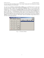
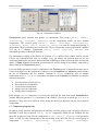
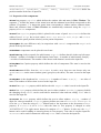
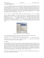
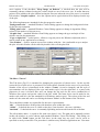
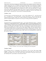
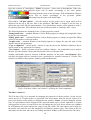
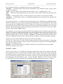
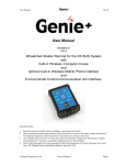
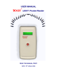
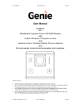
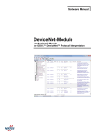
BOLIDE: User manual
BOLIDE Interface
Last update: 28 Sep 2007
___________________________________________________________________________________________________________
BOLIDE Interface
INTRODUCTION
The development of a well-controlled interface for physical programs is quite complicated task. The
interface program code is usually larger than the physical one and needs a lot of time for
elaboration. The idea that an interface program is elaborated and compiled independently on a
physical code is realized in BOLIDE interface.
Interface program BOLIDE (Builder Object Library & Interface Development Environment) was
elaborated with Borland C++ Builder 4 compiler. This program includes necessary elements of the
Visual Components Library (VCL) from the Builder standard kit. The following new components
were written for the realization of this interface scheme: 2D and 3D graphics, counter window,
editor of external text files, executing of external applications. User can change the exterior of the
BOLIDE program and save it without recompiling of source code.
The physical program can be compiled for different operation systems and can be used without
interface. BOLIDE interface doesn’t need to be recompiled, user just executes program and makes
changes in accordance with the physical program. BOLIDE can be used with other applications
with arbitrary language, which have not good interface and use text input and output files.
BOLIDE interface package consists of the executable program “bolide.exe”, binary *.dfm files,
which include information about the exterior. The following text files are used for this interface
scheme:
• input file of the physical program;
• output graphic files of the physical program;
• desktop file for the interface program;
• settings of graphics for the interface program.
For distribution user should have only executable file “bolide.exe”. Binary *.dfm files and all text
files will be generated automatically by the program.
Interface program “bolide.exe” is the executable module under MS Windows operation system.
The timer is automatically running while the program is executed. On the timer event the main
interface operations are produced: loading and saving of files, redrawing of plots, etc. Using the
BOLIDE interface user can edit initial parameters of physical program, execute it, and provide the
information exchange between interface and physical code in real time, draw output graphic files of
the physical program.
1
BOLIDE: User manual
BOLIDE Interface
Last update: 28 Sep 2007
___________________________________________________________________________________________________________
1. Main Window
Main window manages the interface operation and has global menu and buttons which duplicate
actions from the Files menu. The bar title indicates the name of input file. The Files menu includes
the following items (Fig.1.1):
Main window has the following buttons for working with interface:
– open the input file with using Windows Open dialog;
– save input file;
– calculator tool;
– periodic table of chemical elements;
– text editor (by default open betacool.war)
– setup dialog window of the interface program;
– dialog window for elaboration and editing of exterior;
– redraw all graphics;
- restart calculation with new parameters;
- start calculation process;
- pause calculation process;
- restart with changed parameters. If some changes of parameters (in input file via interface)
during calculation were made by user then program will reread initial file and will continue
calculation with new parameters;
- stop calculation. To stop the program with correct OS memory cleaning we advise to use this
item. In this case a special file-marker will be created in the current directory and as soon as
program will find it then it immediately will shutdown with correct saving all the calculated results.
Fig. 1.1. Main window of the BOLIDE interface for BETACOOL program.
1.1. Open
Opens a new input file using the standard MS Windows dialog. The default name and default
filename extension are defined in Options dialog. This filename can be used as input for physical
program when it will be executed from the BOLIDE interface.
1.2. Save
Saves the current input file. If in Options dialog the checkbox Auto Save Input File is chosen the
saving of input file is produced automatically when user load the new input file or exit the
bolide.exe. If user executes the external physical program the input file is always saved.
1.3. Save as…
2
BOLIDE: User manual
BOLIDE Interface
Last update: 28 Sep 2007
___________________________________________________________________________________________________________
Saves the input file with different name. If user doesn’t input point in the filename the default
extension is added to the saved filename.
The menu items Calculator, Periodic table and Editor give user additional service in work with
interface and input or output files. Programming Calculator (Fig. 1.2) can be used for data
preparation for other windows of the program and provides data exchange via system buffer using
standard "copy – past" operations. The Periodic table menu item opens the window of Mendeleev's
periodic table (Fig. 1.3) containing main parameters of chemical elements. Menu item Editor opens
inner text editor (Fig. 1.4) which indicates column and row of the cursor position. For instance in
BETACOOL program it is used for preparation the data for export of MAD file and for editing of
file containing information about ion ring optic structure. This text editor is used also by component
TBrowse to open non-executable file. The window with file of BOLIDE messages Betacool.war is
also can be opened from the menu.
Fig. 1.2. Calculator Window.
3
BOLIDE: User manual
BOLIDE Interface
Last update: 28 Sep 2007
___________________________________________________________________________________________________________
Fig. 1.3. Periodic table Window.
1.4. Editor
Fig. 1.4. Text Editor Window.
Text editor (Fig.1.4) includes usual functions. It can be used together with TBrowse component
which will be described below. From Main window Editor opens the message file with file name
which are described in Warning File Name of Description panel.
1.5. Options
4
BOLIDE: User manual
BOLIDE Interface
Last update: 28 Sep 2007
___________________________________________________________________________________________________________
Fig. 1.5 Options Windows.
Options dialog (Fig.1.5) has setting of the interface program. Most of them are loaded and saved in
the file “bolide.top”, which is automatically generated by the program. Options dialog includes the
following setting:
Preferences
Auto Load Input File – load file on timer event if data of input file was changed
Auto Save Input File – save file on exit
Auto Save Desktop – save desktop on exit
Stop Drawing! – stop drawing graphics, but all another controls remains under operation.
Descriptions
File Name – default file, which is automatically loaded on execute
Extension – file extension, which appears in Open dialog by default
Warning File Name and Maximum Size (kB) – file name for BOLIDE warning and limit in kB
on its size.
Open Dialog Description – descriptions which appears in Open dialog
Separators – letters which are used as separators of values in input file
More
Separate Graphic File Names – save/load graphic setting files with same name to input file
Open Dialog on Run – load Open dialog on execute of bolide.exe program
Maximum Warning Number – maximum number of messages in Warning window
Redraw Timer Interval [s] – interval of timer events in seconds
1.6. Constructor
Constructor (Fig.1.6) is the set of instruments for the elaboration and editing of the interface
interior. It consists of tree panels:
Components – panel of VCL for creating new components;
Property – dialog for editing component properties;
Inspector – total list of visual components in the current project.
5
BOLIDE: User manual
BOLIDE Interface
Last update: 28 Sep 2007
___________________________________________________________________________________________________________
Fig. 1.6. Constructor windows.
Components panel includes two groups of components. First group (TForm, TPanel,
TRadioGroup, TGoupBox, TTabSheet) is the components which can have another
components. The second group (TLabel, TEdit, TCheckBox, TRadioButton,
TComboBox, TSurf, TGraf, TCounter, TBrowse) is used for editing and drawing of
information which is load and saved to text files. Those components are derived from the standard
VCL set of C++Builder. Components TSurf, TGraf, TCounter, TBrowse were
elaborated specially for BOLIDE interface.
For elaboration or editing of the interior do click the TForm button. New window will be created.
Choose any component and click on window. User can change the position and size of any
component holding the left mouse button and Ctrl or Shift keys on the keyboards while moving the
mouse. If Snap to grid is checked the position and size will be change in accordance with value of
editor window on Components panel.
User can change parameter of active component in the Property panel. Component becomes active
if one clicks mouse on the component or chooses it in the Inspector list. Inspector panel includes
the list of components and five buttons. Captions of TForm components, type of another
components and Row, Col or Tag properties are shown in the Inspector list. Buttons are used for
following functions:
•
•
•
•
•
save the interior of total project;
delete the active component;
restore deleted component;
change color of component;
change font of component.
Each window (TForm componet) is saved in the specified file with name mask bolideNN.dfm.
Number NN corresponds to Row parameter of the window. User needs to check the TForm.Row
parameters. They have to be different. After saving the interior on disk user can not restore deleted
components.
1.7. Component properties list
In order to clarify structure and principles of interface work the property "tag" in current version of
BOLIDE is used only to identify TSurf, TGraf components, which are not included into the
input file for physical code. For the components TForm, TPanel, TTabSheet the parameter
"Row" is used, its value corresponds to the line number in an input file. For the second group of
components - TLabel,
TRadioGroup,
TGoupBox,
TEdit,
TCheckBox,
6
BOLIDE: User manual
BOLIDE Interface
Last update: 28 Sep 2007
___________________________________________________________________________________________________________
TRadioButton, TComboBox, TCounter, TBrowse the parameter "Col" is used, its
value corresponds to the position number in the line of an input file. If the "Col" parameter is equal
to zero the corresponding component is not included into output file. Input file can include both
types of data – numbers or strings and using the non-zero "Col" parameter value for Tlabel and
TBrowse components user can save in the input file comments to the numerical parameters or
input file name for loading additional parameters for the physical program – for instance name of
the MAD file. When the mouse pointer is over this field, the hint "#Row : #Col" appears.
1.8. Termination of the calculation process, menu item Redraw
Main algorithm of BETACOOL program provides the calculation of the beam parameter time
dependencies from zero moment to infinity. The calculations can be terminated by Windows
operation system via closing the program window. In this case part of memory used by the program
is not returned to the system and after a few runs of calculation one needs to reboot the system.
Usage of the round crossed button in the right bottom corner of the interface Main window (Fig.
1.1) permits to avoid this disadvantage. If this button is pushed the interface generates and saves in
the current folder the file "Bolide.stp". When the executable program saves the results of
calculations on hard disk, it checks existence of the "Bolide.stp" file, and if it exists the program
removes this file and stops the calculations.
During the calculation process the executable program saves the results into the disk periodically
after given period of time. When the physical program works in parallel with interface program the
last one reads the results from the output files by signals of timer. If, occasionally, when the
interface tries to open the output file this file is used by the physical program the interface "looses"
the corresponding curve and will not to redraw it in the future. To refresh such a "loosed" curve
user has to push button "Redraw" of the interface.
1.9. Warning window
BOLIDE interface has warning window (Fig.1.7) which automatically appears in case of any error.
Usually these errors don’t influence on the physical program. For example, warning windows
appears, when user tries to load non existing file, chooses bad parameters for graphics, inputs bad
value in edit window, etc.
User can close warning window with the mouse double click. The information in the window will
be deleted and warning window will appear in the case of new errors only. Number of warning in
the same time is defined in the Options dialog.
Fig. 1.7. BOLIDE Warning windows.
2. Visual Components
All visual components have properties Row, Col or Tag which correspond to positions in the input
file. Properties Left, Top, Width and Height are used for defining of position and size. The
property Row of components TForm, TPanel, TGroupBox, TTabSheet define the line
number in the input file. The property Col of components TRadioGroup, TCheckBox,
7
BOLIDE: User manual
BOLIDE Interface
Last update: 28 Sep 2007
___________________________________________________________________________________________________________
TRadioButton, TComboBox, TLabel, TEdit, TCounter, TBrowse define the
position number in the line of input file.
2.1. Properties of the components
TForm has property Caption which defines the window title and menu in Main Window. The
separator “|” divides the names of the menu item and the submenu item which corresponds to this
window. If separator “|” is absent the menu items corresponds to window and no submenu items.
Menu and submenu items of Main Window are automatically contracted using the Caption
property of TForm components.
TPanel has Caption property which is placed in the center of panel. BevelWidth defines the
width of bevel. Align has several values: None, Top, Bottom, Left, Right and Client
which define the panel position relatively to the parent component.
TGroupBox has one difference only in comparison with TPanel component that Caption is
placed in the top-left corner.
TTabSheet components can be placed in one frame.
TRadioGroup is the receptacle for radio buttons. Caption defines the title in the top-left corner.
Columns – number of columns for radio buttons. ItemCount – is number of radio buttons. Item[0]…
- are titles of radio buttons. The number of the chosen radio button is saved to the input file.
TCheckBox has Caption property which defines the title of component. The state is saved to the
input file.
TRadioButton differs from the TCheckBox in such a way that user can choose only one
TRadioButton on the same window (panel, group box, tab sheet). The state is saved to the input
file.
TComboBox is the dropdown list. ItemCount –is number of items. Item[0]… - are titles of
items. The number of chosen item is saved to the input file.
TLabel has Caption property which defines the title. Caption value is saved to the input file.
TEdit has Text property which defines the text in editor window. ReadOnly property forbids
the changing of text. TEdit can be used both for numerical value and text editing. Text value is
saved to the input file.
TCounter has Text property which defines the text in editor window. Digits – number of
digits for value presentation. Counter property defines two state of TCounter. If Counter is
set to the true then the using of “<|>”button leads to the increment or the decrement of Text
property. If Counter is set to false then the letter in Text property is changed to value
“0123456789.-E”. Use right mouse button for rotation of “<|>”button. In this case the “<|>”
button can be used for adding or removing letters in Text property. Text value is saved to input file.
TCounter can be used for numerical value only. Text value is saved to the input file.
8
BOLIDE: User manual
BOLIDE Interface
Last update: 28 Sep 2007
___________________________________________________________________________________________________________
2.2. Component TBrowse
TBrowse component is used to save in input file the names of the files with additional parameters
for the physical program and to start executable file of the physical program. For instance, if user
pushes the button Open of the TBrowse component with properties presented in the Fig 2.1, the
program, which name is presented as the property "text" (and also is indicated in the edit window of
the component), will be started with current input file (its name and path indicated in the upper
string of the interface Main Window – see Fig. 1.1) and with additional parameter "rates", which
is presented in the field of the property "Parameters".
TBrowse has Text property which defines the external filename. Parameters property
(Fig.2.1) defines the parameter line when user presses Open button and executes an external
application. If the filename in Text property is not executable program then this file will be open
with internal Editor. “/:” – full path for the input file, “/%” – filename of the input file without
full path and extention, “/@” – extension of the input file. User can type any parameters and
combinations with filename of input file. Filter – the file mask which are used in Open dialog
when user press Find button. Text before separator “|” appears in the dialog, after follows the file
mask.
Fig. 2.1. Properties of TBrowse component
As a result the DOS window application will be started by the following command string:
C:\BETACOOL\BETACOOL.EXE Betacool.bld /rates
Property "FullPath" is equal to "false" it means that the input file *.bld must be placed in the
same folder as the executable file. In this example the Property "Col" is equal to zero, it means that
the executable file name is not saved in the input file.
2.3. TGraf.
Visual component TGraf can be taken from the visual component constructor and put on any
TPanel of necessary (arbitrary) TForm. The special TGraf Properties Dialog can be called by right
mouse clicking on the TGraf component. Automatically this dialog has a caption with the name of
chosen TGraf, its Tag number, and (if this TGraf contains several curves) name of the curve (by
default the first curve). The name of TGraf and its Tag number can be changed via Constructor.
This dialog window has a very comfortable and fulfilled interface for editing and changing TGraf
parameters. It has 5 TabSheets: Axis, Grids, Other, Curves, Values (Fig.2.2).
Every action on editing or changing can be approved and saved by clicking the button Accept, or
cancelled by clicking the button Cancel.
9
BOLIDE: User manual
BOLIDE Interface
Last update: 28 Sep 2007
___________________________________________________________________________________________________________
Some preface words about managing the Properties Dialog. It has standard elements of editing: edit
windows, check boxes, lists, etc. Besides, it has specially developed visual components for numbers
editing - TCounter, they are the part of edit windows. There are three ways to manage the numbers:
increments (decrements) with big arrows near by the edit window let user to change number by two
every time, or if the logarithmic scale is ON then by one order. At the same time there is a control
arrows on the right side of the edit window, they let user to increase (decrease) the number by unit
in the first mode. The second mode can be switched on by right mouse click over this element, and
then it "rotates", and works like a "by one order" increment (decrement).
Fig.2.2. Tab sheet “Axis” and “Grids” of Dialog for TGraf component.
Double click over the plot field calls the new window with the plot – it is comfortable for
monitoring the plot evolution in larger scale.
Tab Sheet "Axis"
The panel (Fig.2.2) is divided in two parts – one is for the ordinate axis (Y – axis), another one – is
for abscissa (X – axis). Both axis's have the following properties which can be edited: maximum
and minimum values on the axis, the number of displayed digits, the caption of axis, the type of
scaling (decimal or logarithmic).
Tab Sheet "Grids"
The panel (Fig.2.2) is also divided in two parts – one is for the ordinate axis (axis 1) – on the top,
another one – is for the abscissa (axis 0) – on the bottom. User can change number of ticks and
grids (major and minor) to be drawn. Visualizing of major and minor grids can be switched on (off)
by special checkboxes located opposite the tick number edit windows. Also there is a possibility to
control the style of lines to draw the corresponded grids, its colour and the width. Button "Color"
calls the standard Windows Colour Dialog. Under the panel with grids properties a checkbox
"Redraw grids" is located – this is a special tool which allows to redraw the axis and grids after plot
drawing completion (sometimes plots can be drawn over the grids, if too much of them, and it is not
comfortable then to analyze the plot with lack of grids).
Tab Sheet "Other"
This Tab Sheet (Fig.2.3) is responsible for the appearance of the plot. Edit window Legend –
remains a space with specified width on the right hand of the plot for the legend, if the number is
not a zero. The curve caption will be shown.If the checkbox "Show curve values" is checked then
the numerical value of the last point of the curve will be displayed on the legend instead of the
10
BOLIDE: User manual
BOLIDE Interface
Last update: 28 Sep 2007
___________________________________________________________________________________________________________
curve caption. If the checkbox "Keep Image on Redraw" is checked then the plot will be
constantly redrawn without loosing the values which are out of the curve size. It means that new
points will be added to the plot without loosing the first ones when the size of the curve is exceeded.
Edit window "Graphic caption" – here the caption can be typed which will be displayed on the top
of the plot.
The following buttons are intended for the plot properties control:
"Background color" – standard Windows Colour Dialog appears to change the background colour
for the plot representation.
"Filling point color" – standard Windows Colour Dialog appears to change in legend the filling
colour for the markers of chosen curve.
"Graphic font" – standard Windows Font Dialog appears to change the type and style of font
which is used in plot appearance.
"Copy to clipboard" – useful option – allows to copy the plot to the Windows clipboard, after it
can be pasted in any application as a bitmap.
"New window" – opens a separate screen-size window with plot – the comfortable way to analyze
the plot. Also this window can be called by double-click over the plot field.
Fig.2.3. Tab sheet “Other” and “Curves” of Dialog for TGraf component.
Tab Sheet "Curves"
This Tab sheet (Fig.2.3) is intended for changing the properties of chosen curve. On the top-left
corner the list of plot curves is presented. User must choose from the list the curve to be processed.
Number of the curves is introduced in the window "Count" (it can be changed), and the style of
representation will be displayed (line type and marker style). On the right there is a panel with
properties of curve is located. Here user can change the line style for the curve (standard kit of
Windows line styles) and put the value for the line width. The same choice can be made for the
marker style and size (also the standard kit of Windows marker types). The colour of the line and
marker are the same and can be set clicking the button "Color" on the bottom of the Tab sheet.
Three checkboxes under are responsible for the curve representation.
"abs" – if checked makes all the points with absolute value within the curve
"visible" – if checked the curve is visible on the plot, if not checked – the curve is hidden.
"autoload" – if checked the curve is constantly uploading and renewed from the file with data.
The edit window under - is a path to file with curve data (*.cur). The path can be manually written
in this edit window, or can be chosen with standard Windows "Open File Dialog". This dialog can
be called with "Load" button on this Tab sheet. At the same way any curve can be saved to
specified or newly created file. The procedure is similar to any Windows application one. User must
11
BOLIDE: User manual
BOLIDE Interface
Last update: 28 Sep 2007
___________________________________________________________________________________________________________
click the "Save" button and specify the filename for the curve to be saved. To reset the curve data
user must click the "Reset" button.
The situation can occur when user had specified in the program code the filename and path for the
curve to be saved, but during the interface operation curve doesn’t appear on the screen. It is always
in normal way when the first time curve is visualized. Here user must call the TGraph properties
Dialog and in current Tab Sheet: Curve (preliminary having chosen the curve) with the "Load"
button point the file with curve data, and after to check the "autoload" checkbox.
Also there are two edit windows ale placed on the current Tab Sheet:
"Size" – specifies the size of the curve (number of point to keep). Then bigger this value then more
intensive memory usage is needed for the operation, and correspondingly it will slow the
calculation speed.
"Redraw" – specifies the curve size (number of points) to be periodically redrawn by BOLIDE
interface per one event of System Timer.
Tab Sheet "Values"
This Tab sheet (Fig.2.4) is intended for listing the curve data values. Two columns represent
correspondingly abscissa and ordinate values, which are used for the curve plotting. Here all the
curve values are listed (accordingly to the curve size). And user can monitor the precise values of
the points. This array of curve data in two-column format is saved in the specified file (*.cur) – see
the Tab Sheet "Curves". This file can be used after by any Windows (not only) application for
analyzing the data and drawing necessary plots.
Fig.2.4. Tab sheet “Values” of Dialog for TGraf component.
2.4. TSurf.
Visual component TSurf can be taken from the visual component constructor and put on any TPanel
of necessary (arbitrary) TForm. The special TSurf Properties Dialog can be called by right mouse
clicking on the TSurf component. Automatically this dialog has a caption with the name of chosen
TSurf, its Tag number, and (if this TSurf contains several surfaces) name of the surface (by default
the first curve). The name of TSurf and its Tag number can be changed via Constructor. This dialog
window has a very comfortable and fulfilled interface for editing and changing TSurf parameters. It
has 6 TabSheets: Axis, Grids, Other, Surfaces, Values, Cross. Every action on editing or changing
can be approved and saved by clicking the button Accept, or cancelled by clicking the button
Cancel.
12
BOLIDE: User manual
BOLIDE Interface
Last update: 28 Sep 2007
___________________________________________________________________________________________________________
Some preface words about managing the Properties Dialog. It has standard elements of editing: edit
windows, check boxes, lists, etc. Besides, it has specially developed visual components for numbers
editing - TCounter, they are the part of edit windows. There three ways to manage the numbers:
increments (decrements) with big arrows near by the edit window let user to change number by two
every time, or if the logarithmic scale is ON then by one order. At the same time there is a control
arrows on the right side of the edit window, they let user to increase (decrease) the number by unit
in the first mode. The second mode can be switched on by right mouse click over this element, and
then it "rotates", and works like a "by one order" increment (decrement).
Tab Sheet "Axis"
The panel (Fig.2.5) is divided into three parts – one is for the ordinate axis (Y – axis), the second
one – is for abscissa (X – axis), and the third – is for the vertical axis (Z - Axis). All axis's have the
following similar properties which can be edited: maximum and minimum values on the axis, the
number of displayed digits, the caption of axis, the type of scaling (decimal or logarithmic).
Tab Sheet "Grids"
The panel (Fig.2.5) is also divided into three parts – one is for the vertical axis (axis 2) – on the top,
another one – is for the abscissa (axis 0) – in the middle, and the 3rd is for the ordinate axis (axis 1)
– on the bottom of the panel. User can change number of ticks and grids (major and minor) to be
drawn. Visualizing of major and minor grids can be switched on (off) by special checkboxes located
opposite the tick number edit windows. Also there is a possibility to control the style of lines to
draw the corresponded grids, its colour and the width. Button "Color" calls the standard Windows
Colour Dialog. Under the panel with grids properties a checkbox "Redraw grids" is located – this is
a special tool which allows to redraw the axis and grids after plot drawing completion (sometimes
plots can be drawn over the grids, if too much of them, and it is not comfortable then to analyze the
plot with lack of grids).
Fig.2.5. Tab sheet “Axis” and “Grids” of Dialog for TSurf component.
Tab Sheet "Other"
This Tab Sheet (Fig.2.6) is responsible for the appearance of the 3-D plot. Edit window Land
Legend – remains a space with specified width value on the right hand of the 3-D plot for the
legend, if the number is not a zero. The surface caption will be shown. This option can be used if
the "landscape like" representation is chosen for the surface.
13
BOLIDE: User manual
BOLIDE Interface
Last update: 28 Sep 2007
___________________________________________________________________________________________________________
Here also a choice of "land filling": "Filled" is foreseen – either color or black&white. If the color
filling is chosen, then different layers will be drawn accordingly to the color palette:
chosen,
then
increasing from the white to the red range. If the black&white filling is
different layers will be drawn accordingly to the greyscale palette:
increasing from the white to the black range.
Edit window "3-D plot caption" – here the caption for the surface can be typed which will be
displayed on the top of the plot. Here is the checkbox "3D View" is located. It lets the user to
choose the type of the 3D plot representation: if it is checked then surface will be plotted as usual 3D isometric projection. If not checked, then plot will be presented as "landscape like" layers.
The following buttons are intended for the 3-D plot properties control:
"Background color" – standard Windows Colour Dialog appears to change the background colour
for the plot representation.
"Filling point color" – standard Windows Colour Dialog appears to change in legend the filling
colour for the markers of chosen surface.
"Graphic font" – standard Windows Font Dialog appears to change the type and style of font
which is used in plot appearance.
"Copy to clipboard" – useful option – allows to copy the plot to the Windows clipboard, after it
can be pasted in any application as a bitmap.
"New window" – opens a separate screen-size window with plot – the comfortable way to analyze
the plot. Also this window can be called by double-click over the plot field.
Another comfortable option is foreseen in Bolide interface: on the panel "Axis Rotation" three
specially developed tools are located to have a possibility for isometric rotation of 3-D plot. This
rotation is available in three planes: frontal, profile and horizontal.
Fig.2.6. Tab sheet “Other” and “Surface” of Dialog for TSurf component.
Tab Sheet "Surfaces"
This Tab sheet (Fig.2.6) is intended for changing the properties of chosen surface. On the top-left
corner the list of 3-D plot surfaces is presented. User must choose from the list the surface to be
processed. Number of the surfaces is displayed in the window "Count" (it can be changed), and the
style of representation will be displayed (line type and marker style). On the right there is a panel
with properties of curve is located. Here user can change the line style for the surface net (standard
kit of Windows line styles) and put the value for the line width. The same choice can be made for
the marker style and size (also the standard kit of Windows marker types). The colour of the line
and marker are the same and can be set clicking the button "Color" on the bottom of the Tab sheet.
14
BOLIDE: User manual
BOLIDE Interface
Last update: 28 Sep 2007
___________________________________________________________________________________________________________
Five checkboxes under are responsible for the curve representation.
"Absolute" – if checked makes all the points with absolute value within the surface (all the values
are turned to positive)
"Land" – type of 3-D plot representation: either isometric view or "landscape like" view.
"Fill" – if checked, then polygons between the surface nodes will be filled with specified color
palette.
"Visible" – if checked the surface is visible on the plot, if not checked – the surface is hidden.
"Autoload" – if checked the surface is constantly uploading and renewed from the specified file
with data (*.sur) .
The edit window under - is a path to file with surface data (*.sur). The path can be manually written
in this edit window, or can be chosen using the standard Windows "Open File Dialog". This dialog
can be opened with "Load" button on this Tab sheet. At the same way any surface can be saved to
specified or newly created file. The procedure is similar to any Windows application one. User must
click the "Save" button and specify the filename for the surface to be saved. To reset the surface
data user must click the "Reset" button.
The situation can occur when user had specified in the program code the filename and path for the
surface to be saved, but during the interface operation surface doesn’t appear on the screen. It is
always in normal way when the first time curve is visualized. Here user must call the TSurf
properties Dialog and in current Tab Sheet: "Surfaces" (preliminary having chosen the surface)
with the "Load" button point the file with surface data, and after to check the "autoload" checkbox.
Also there are three edit windows ale placed on the current Tab Sheet:
"X" and "Y"– specify the size of the surface (number of point to keep in both planes). Then bigger
this value then more intensive memory usage is needed for the operation, and correspondingly it
will slow the calculation speed.
"Redraw" – specifies the surface size (number of points) to be periodically redrawn by Bolide
interface per System Timer event.
Tab Sheet "Values"
This Tab sheet (Fig.2.7) is intended for listing the surface data values. First column of the table
represents abscissa, first row of the table represents ordinate values, and the table itself contains the
Z-coordinate values corresponded to the X- and Y- values, which are used for the surface plotting.
User can monitor the precise values of the points. This array of surface data table-lake format is
saved and kept in the specified file (*.sur) – see the Tab Sheet "Curves". This file can be used after
by any Windows (not only) application for analyzing the data and drawing necessary 3-D plots.
15
BOLIDE: User manual
BOLIDE Interface
Last update: 28 Sep 2007
___________________________________________________________________________________________________________
Fig.2.7. Tab sheet “Values” and “Cross” of Dialog for TSurf component.
Tab Sheet "Cross"
This Tab sheet (Fig.2.7) is intended for the analyzing the 3-D plot. Here is the option for slicing the
surface is developed. Here is a 2-D plot intended for this purpose is located. In the ComboBox
"Cross On" user can change the plane for cross-section – either on abscissa or ordinate. Here is the
choice of plane is offered (if axis have captions then it is easier to make a choice). Under this
ComboBox the index number of the cross-section can be chosen "Line number" (number of lines
is equal to the size of the surface – this value is set in Tab Sheet "Surfaces": "X" or "Y"). User can
list in on-line mode all the cross-sections of specified surface. Informative window "Cross value"
shows the value of cross-section of drawn curve with the vertical axis. CheckBox "Integral" – is
intended to show the integral cross-section of the surface, if checked.
Parameters of this 2-D plot can be edited or changed if user calls a TGraf Properties Dialog with
right-button mouse click.
3. Format of the input file
Input file has the name “bolide.bld” on default. BOLIDE interface can load any text file, which is
written in the specified format. Input file can include both numerical values and string constants.
Separators are the tabulator symbol or any number (more than one) of spaces by default. User can
add more separators in Separators edit window of Options dialog. The same input file is used for
physical program.
For visualizing the values and strings from the input file the following scheme is used. Components
of first group (TForm, TPanel, TRadioGroup, TGoupBox, TTabSheet) have Row
parameter which corresponds to the line number in input file. In second group (TLabel,
TEdit, TCheckBox, TRadioButton, TComboBox, TCounter, TBrowse)
parameter Col defines the number in the line. These parameters should have the positive value,
otherwise component doesn’t appear in the input file. If Constructor dialog is opened and the
mouse is currently moving over the component then user can check the pair of Row and Col
parameters.
TSurf, TGraf components do not correspond to the input file and have own files for saving the
plot parameters (“bolide.grf”, “bolide.srf”). These components should have the different values of
Tag parameter. For on-line plot drawing user can load graphic file in the Dialog panel of the plot
(right mouse click on TSurf or TGraf component) and set Autoload checkbox. Reading and
redrawing of plots occur on the timer events. If Autoload checkbox isn’t set, then user can redraw
all graphics with using of Redraw button in Main window.
16