1
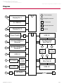
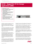
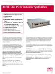
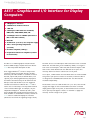
Embedded Solutions
for Transportation and Industrial Markets
www.men.de/products/08AE51-.html
AE51 – Graphics and I/O Interface for Display
Computers
n 2 DisplayPort® interfaces
n 2 Gb Ethernet on M12 connectors
n 1 USB 2.0
n 2 PCI Express® Mini Card slots for WLAN,
UMTS, GPS, GSM, HSDPA, EDGE, LTE
n 2 SA-Adapter slots for 2 UARTs (alternative: 1
IBIS or GPS and 1 CAN bus)
n HD audio
n 24 VDC nom. (9 to 36 V) class S2 power supply
n -40 to +85°C operating temperature
(screened)
n EN 50155 compliant (railways)
n Prepared for ISO 7637-2 compliance (E-mark
for automotive)
The AE51 is a combined graphics and I/O interface
board for MEN's display computer electronics like the
SC24 SBC and possible subsequent models.
Three rugged AirMax VS® connectors transport the
various I/O signals from the SBC board to the AE51,
where they are made available on standard connectors
like USB, 9-pin D-Sub (serial I/O and HD audio, both
optional), 8-pin M12 (Gigabit Ethernet), DisplayPort®
and SATA. Touch functionality can be realized via the
USB port. Note that the AE51 is just one suggested
interface board variant for SBCs like the SC24 and as
such it does not necessarily cover all possible interfaces
of the connected SBC board. For example, only two
independent DisplayPort® interfaces (B and C, with
their individual AUX and USB channel respectively) are
made available on standard DP connectors, whereas an
SC24 offers two additional DisplayPort® interfaces
(identical to the former two regarding image content).
AE51 Data Sheet / 2014-01-17
The AE51 serves as a 2x PCI Express® Mini card carrier for the connected
SBC board. Two SIM card slots are available. By default, one is used for
each of the two PCI Express® Mini cards, but the first PCI Express® Mini
card can also switch between the two SIM cards as an option. The
necessary antenna connectors can be led to a front panel.
As an option, a SATA interface from the SBC board is also made available
along with a 4-pin power connector for the drive, however the AE51 is
not designed as a SATA HDD/SSD carrier board - the drive must be
mounted independently.
The board also serves as a 30W 24 VDC nom. (9 to 36 V) class S2 widerange power supply for the connected SBC board. If the connected
display panels require more power, an external PSU can be connected
via an optional power bypass connector on the AE51 to supply the
necessary 12 VDC voltage for the system.
Page 1
Embedded Solutions
for Transportation and Industrial Markets
www.men.de/products/08AE51-.html
Diagram
G
F
DisplayPort 1
2x USB 2.0
Front connector
G
Graphics connector
IO
I/O connector
B
Onboard connector
DisplayPort 2
F
F
F
Power Supply
Options
B
IO
USB 2.0
F
10/100/1000Base-T
Ethernet
PCI Express®
Mini Card A
10/100/1000Base-T
Ethernet
F
F
F
SIM
Card A
SIM
Card B
USB 2.0
F
F
F
F
SA-Adapter
UART
or CAN
PCI Express®
Mini Card B
F
SA-Adapter
UART
or GPIO
USB 2.0
F
B
AE51 Data Sheet / 2014-01-17
HD Audio
SATA
B
Page 2
Embedded Solutions
for Transportation and Industrial Markets
www.men.de/products/08AE51-.html
Technical Data
Board-to-board connection
n
3 AirMax VS® connectors
o To SBC board's graphics and I/O connectors P1/P2/P4
Front I/O
n
2 DisplayPort® interfaces
o AUX channels and hot plug detection
o USB channels optional
HD audio
o HD audio codec (Realtek ALC268)
o Audio stereo in
o Audio stereo out
o SPDIF out
o Via 10-pin onboard connector
2 Gigabit Ethernet
o Via M12 connectors
1 USB 2.0
o Via Type A connector
2 SA-Adapter slots for serial I/O
o 1 UART or IBIS, GPS
o 1 UART or CAN bus
8 status LEDs
o 4 for Ethernet link and activity status
o 2 for general board status
o 2 for power supply status
n
n
n
n
n
2 PCI Express® Mini Card slots
n
n
n
Accelerometer / Magnetometer
n
n
For functions like Wi-Fi, WIMAX, GSM/GPRS, UMTS
2 SIM card slots
PCI Express® and USB interface
3 acceleration channels
o 2 independent programmable interrupt generators for free-fall and motion detection
3 magnetic field channels
o ±1.3 to ±8,1 gauss magnetic field full-scale
Miscellaneous
n
Gold Cap to buffer real-time clock on connected SBC board
Electrical Specifications
n
Isolation voltage:
o Ethernet ports: 1,500 VDC
o DC/DC: 1,500 VDC
Supply voltage:
o 24 VDC nom. (9 to 36 V)
o EN 50155 power interruption class S2
Power output: 12 VDC nom.
Power consumption: Up to 30 W
n
n
n
Mechanical Specifications
n
n
Environmental Specifications
n
Temperature range (operation):
o 0..+60°C up to -40..+85°C (screened)
o Fanless operation
Temperature range (storage): -40..+85°C
Relative humidity (operation): max. 95% non-condensing
Relative humidity (storage): max. 95% non-condensing
Altitude: -300 m to +3,000 m
Shock: 50 m/s², 30 ms
Vibration (function): 1 m/s², 5 Hz - 150 Hz
Vibration (lifetime): 7.9 m/s², 5 Hz - 150 Hz
Conformal coating on request
n
tbd. @ 40°C according to IEC/TR 62380 (RDF 2000)
n
n
n
n
n
n
n
n
MTBF
AE51 Data Sheet / 2014-01-17
Dimensions: approx. 170 mm x 132 mm x 30 mm
Weight: approx. 100 g
Page 3
Embedded Solutions
for Transportation and Industrial Markets
www.men.de/products/08AE51-.html
Technical Data
EMC
n
n
Conforming to EN 55022 (radio disturbance), IEC 61000-4-2 (ESD) and IEC 61000-4-4 (burst)
Prepared for certification according to ISO 7637-2 (E-mark) requirements
Configuration & Options
Standard Configurations
Article No.
Input Voltage
HD Audio Adapter to Front
Connector
Antenna Connectors
08AE51-00
24 VDC nom.
No
No
Options
I/O
n
n
n
DisplayPorts with USB channel instead of AUX channel
HD audio
o Ribbon cable adapter to 9-pin D-Sub front I/O connector
Antenna connectors
®
o For functions like Wi-Fi, WIMAX, GSM/GPRS, UMTS in combination with PCI Express Mini Card(s)
o Reverse SMA connector
Mass Storage
n
Serial ATA (SATA)
o One port for external hard-disk/solid-state drive
Miscellaneous
n
3-axis accelerometer and 3-axis magnetometer
Electrical Specifications
n
Input voltage 36 VDC nom. via front connector (alternate internal PSU)
Input voltage 12 VDC via optional onboard power bypass connector
n
As the product concept is very flexible, there are many other configuration possibilities. Please contact our sales team if you do not find your
required function in the options. Please note that some of these options may only be available for large volumes.
AE51 Data Sheet / 2014-01-17
Page 4
Embedded Solutions
for Transportation and Industrial Markets
www.men.de/products/08AE51-.html
Ordering Information
Standard AE51 Models
08AE51-00
Graphics & I/O interface board for display and box computers; 2x DisplayPort®, 2x Gb
Ethernet, 1x USB, 2x PCI Express® Mini card slot, 2x SIM card slot, 2x SA-Adapter slot,
PSU 24 VDC, -40 to +85°C screened
Related Hardware
08AE63-00
DisplayPort® to LVDS converter, temperature sensor, ambient light, touch input, key
control, input voltage 12V..24V, -40°..+85°C screened
08SC24-00
Multi-display SBC with AMD T48N, 1.4 GHz, 2 GB RAM, SD card slot, mSATA slot, 2x2
DisplayPorts, 12V PSU (non isolated), prepared for -40 to +85°C screened via conductive
cooling
15PX04-00
Audio interface for mobile wireless cards, with SIM card holder, -40..+85°C screened
PCI Express® Mini Cards
15PX01-00
GLONASS & GPS PCI Express® MiniCard (full size), 3-axis Gyro sensor, -40..+85°C with
qualified components
SA-Adapters
You can find a more detailed overview of possible carrier board/SA-Adapter combinations along with
software support in our option matrix (PDF).
08SA01-06
RS232, not optically isolated, -40..+85°C screened
08SA02-07
RS422/485, full duplex, optically isolated, -40..+85°C screened
08SA03-01
1 RS232, optically isolated, -40..+85°C screened
08SA08-01
CAN ISO high-speed, optically isolated, -40..+85°C screened
08SA22-00
IBIS master SA-Adapter, -40..+85°C screened
08SA22-01
IBIS slave SA-Adapter, -40..+85°C screened
08SA25-00
GPS receiver, isolated, -40..+85°C screened
08SA26-00
RS422 with 15-pin D-Sub connector, with handshake signals (RTS, CTS, DCD, DTR),
coated, -40..+85°C screened
Miscellaneous Accessories
0780-0005
DisplayPort® to DVI-D adapter, 20 cm
Documentation
Compare Chart Standard and Custom Panel PCs » Download
20AE51-00
AE51 Data Sheet / 2014-01-17
AE51 User Manual
Page 5
Embedded Solutions
for Transportation and Industrial Markets
www.men.de/products/08AE51-.html
Contact Information
Germany
France
USA
MEN Mikro Elektronik GmbH
Neuwieder Straße 3-7
90411 Nuremberg
Phone +49-911-99 33 5-0
Fax +49-911-99 33 5-901
MEN Mikro Elektronik SAS
18, rue René Cassin
ZA de la Châtelaine
74240 Gaillard
Phone +33 (0) 450-955-312
Fax +33 (0) 450-955-211
MEN Micro Inc.
860 Penllyn Blue Bell Pike
Blue Bell, PA 19422
Phone (215) 542-9575
Fax (215) 542-9577
[email protected]
www.men.de
[email protected]
www.men-france.fr
[email protected]
www.menmicro.com
The date of issue stated in this data sheet refers to the Technical Data only. Changes in ordering information given herein do not affect the date of issue. All brand or product names are
trademarks or registered trademarks of their respective holders.
MEN is not responsible for the results of any actions taken on the basis of information in the publication, nor for any error in or omission from the publication.
MEN expressly disclaims all and any liability and responsibility to any person, whether a reader of the publication or not, in respect of anything, and of the consequences of anything,
done or omitted to be done by any such person in reliance, whether wholly or partially, on the whole or any part of the contents of the publication.
The correct function of MEN products in mission-critical and life-critical applications is limited to the environmental specification given for each product in the technical user manual.The
correct function of MEN products under extended environmental conditions is limited to the individual requirement specification and subsequent validation documents for each product
for the applicable use case and has to be agreed upon in writing by MEN and the customer.Should the customer purchase or use MEN products for any unintended or unauthorized
application, the customer shall indemnify and hold MEN and its officers, employees, subsidiaries, affiliates, and distributors harmless against all claims, costs, damages, and expenses,
and reasonable attorney fees arising out of, directly or indirectly, any claim or personal injury or death associated with such unintended or unauthorized use, even if such claim alleges
that MEN was negligent regarding the design or manufacture of the part.
In no case is MEN liable for the correct function of the technical installation where MEN products are a part of.
Copyright © 2015 MEN Mikro Elektronik GmbH. All rights reserved.
AE51 Data Sheet / 2014-01-17
Page 6