1
SSDCP Manual
Introduction ………………………………………………………..
12
Installation
Installing SSDCP ……………………………………………….. 14
Adding SSDCP to the AutoCAD search path………………… 24
Adding SSDCP to the AutoCAD menu by script …………… 29
Manually Adding SSDCP to the AutoCAD menu ……………. 31
Uninstalling SSDCP ……………………………………………. 36
Uninstalling SSDCP license..………………………………….. 38
Moving your SSCP license to another computer ……………. 41
Updates …………………………………………………………... 44
Buying and installing additional SSDCP modules …………….45
Setting Up SSDCP
SSDCP Setup
Using SSDCP setup to start a drawing ……………….
Prototype Drawings ……………………………………..
Selecting Drawing Scales ………………………………
Drawing Scales ………………………………………….
Using DWT Templates …………………………………
49
51
54
55
57
SSDCP Manual
SSDCP Utilities
Plot ……………………………………………………….. 58
Current drawing info ……………………………………. 58
Print total time on drawing ……………………………… 58
Timesheet Program …………………………………….. 59
Error Screen ON ………………………………………… 62
Error Screen OFF ………………………………………. 62
Layer Controls
Change entity to another layer ………………………… 62
Change current layer to: ……………………………….. 62
OBJ
FS
BOR
HL
FSH
LL
CNTR
JOIST
Setup Job Folders
Adding a subfolder……………………………………… 62
Renaming a folder ……………………………………. 64
Toolbars ………………………………………………………… 69
Customizing Toolbar buttons ………………………………. 70
SSDCP Defined functions ……………………………………. 72
Suggestions for using SSDCP ……………………………… 73
SSDCP Manual
Entering Dimensions (imperial) ……………………………. 76
Adding Material to Data Files ………………………………. 78
Selecting Steel Shapes ……………………………………… 80
Text Styles …………………………………………………….. 81
Calculating Plotted Text Height …………………………… 83
Conversion chart for inserting blocks ……………………. 83
Help ………………………………………………………….. 85
Level Beams ……………………………………………….. 87
Columns …………………………………………………….. 90
Beam/Column Add-Ons
Add Beam Pour Stop …………………………………………..
Add Beam Lintel Plates ………………………………………..
Add Beam Outriggers …………………………………………..
Column web safety clip …………………………………………
Column web stiffener plates…………………………………….
Column end prep ………………………………………………..
104
108
111
113
115
116
Other Main Programs
For Erection
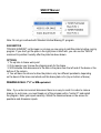
Erection/Anchor Bolt Plans ……………………………. 118
Anchor Bolt Settings ……………………………………. 120
Anchor Bolt Details …………………………………….. 123
SSDCP Manual
Draw Block Wall Sections ……………………………… 126
Draw Brick Wall Sections ……………………………… 132
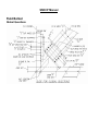
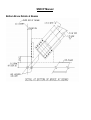
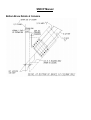
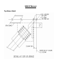
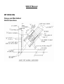
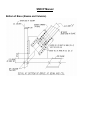
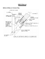
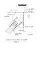
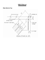
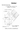
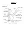
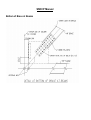
Sloped or Skewed Beams …………………………………… 137
Sloped Beam (Old)
Sloped Beam (New)
Skewed Beams, plates, layout
Girts/Sag Rods/Lintels ……………………………………….. 159
Girts
Sag Rods
Lintels
Add Notch or Block
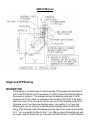
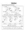
Angle/WT (Horizontal Brace) ………………………………… 176
Horizontal WT Brace
Horizontal Angle Brace
Horizontal Brace Plates
Horizontal Double Angles (similar to WT)
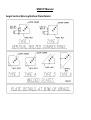
Angle/WT/Knee Brace (Vertical Brace) ……………………. 184
Vertical WT Brace
Brace Plate for Vertical WT Brace
Vertical Angle Brace for Single Gage
Brace Plate for Vertical Angle Brace (single gage)
Vertical Angle Brace for Double Gage
Brace Plate for Vertical Angle Brace (double gage)
Knee Brace
TS/Pipe Vertical Bracing …………………………………….. 194
TS/Pipe Field Welded
Brace Plate for TS/Pipe (Field Weld)
TS/Pipe Field Bolted
Brace Plate for TS/Pipe (Bolted)
SSDCP Manual
Wide Flange Vertical Brace ………………………………………….. 210
Bolt Flange Web/Angles
Brace Plate for Bolt Flange Web/Angles
Bolt Web Only
Brace Plate for Bolt Web
Bolt Flange Web/Weld Plates
Brace Plate for Bolt Flange Web/Weld Plates
Bolt Web Only/Plates Web View
Brace Plate for Bolt Web Only/Plates Web View
Horizontal Brace Struts ……………………………………… 241
Angle Struts
WT Struts
Miscellaneous Bracing Programs …………………………. 245
Quick Check
Odd Bracing Angle
Generic Brace Plates
Stair Programs ………………………………………………… 247
Pan (Sloping Riser)
Pan (30 degree Bullnose)
Pan (Straight Riser)
Pan (Landing Details)
Grating Treads Bolted
Grating Treads Welded
Checkered Plate Treads
Stair Bracing
Stair Handrail …………………………………………………... 274
Wall Rail
Single Mid-Rail
Multi Mid-Rail
Handrail Panels
SSDCP Manual
Level Handrail …………………………………………………. 287
Pipe
Handrail Panels
Angle N/A
Truss Work ……………………………………………………… 298
Welded Angles
Bolted Angles
Welded Pipe
Welded Truss
Pipe Intersection
Hoppers/Plate Work …………………………………………… 310
Miscellaneous Programs …………………………………….. 316
Plate Girder Section
Checkered Floor Plate Plan
Add Notch or Block
Tilt Up Panels
Full Size Templates …………………………………………… 323
For Base Plate
For Brace Plate
Wrap Around Plate
Draw Steel Shapes
Front Views ………………………………………………………. 326
Stick of Steel
Continuous Angle or Bent Plate
Section Views ……………………………………………………. 326
SSDCP Manual
Pipe Shape
TS / HSS Shape
Hatch Sections
Section Thru Bent Plate
AISC Shape Information ……………………………………….. 328
Draw Joist / Girders …………………………………………….. 329
BOM / Material Marking ………………………………………… 336
BOM Setup / Sheet Layout
Add a Shipping Mark
Add an Assembly Mark
Add Material Label on Detail
Fill In Bill of Material
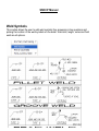
Weld Symbols ……………………………………………………… 346
Print or Count Bolts ……………………………………………… 348
Forms, Cut Section Arrows, Hatch Patterns …………… 348
Create any Form
Cut Section Arrows
Standard Hatch Patterns
Steel
Concrete
Wall 1/8” Scale
Wall 1” Scale
Grating-Bearing Bars Horizontal
Grating-Bearing Bars Vertical
Checkered Plate
SSDCP Library ……………………………………………………
Insert / Add / Modify Blocks
Make Block and Slide For Library
349
SSDCP Manual
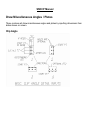
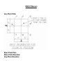
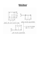
Draw Miscellaneous Angles / Plates ……………………… 354
Clip Angle
Any Plain Plate
Base Plate Plan
Base Plate Elevation
Cap Plate Elevation
Corner Base Plate
Dimension Any Plate
Shear Bars
Draw Miscellaneous Details …………………………………
360
Beam Outrigger Detail
4-Sided Frames
Roof Frames
Anchor Bolt Details
Draw Box
Draw Cloud
Draw Arcs with Dimensions
Draw Shims
Draw Studs
Draw Expansion Bolts
Blow Up Detail
Camber Diagram
Draw Miscellaneous Holes …………………………………..
369
Round Hole
Slots
Flange Hole
Add Holes to Details
Draw Bolt Circle
Text (Change or Edit) ……………………………………………. 371
Change Text
SSDCP Manual
Text on Arc
Blow Up Text to Read
Cross Hair Angle …………………………………………………
371
Reset to 0 –90
Set Angle
Leaders for Holes or Text …………………………………….. 372
Bevels / Lines ……………………………………………………… 372
Draw Bevel Figure
Rotate to Bevel
Draw Sloping Line
Trim Multi Lines
Extend Multi Lines
Hump Over Line
Break Material
Break Short Line
Change Pline Width
Calculator …………………………………………………………..
Triangles
Multiply
Divide
Add/Subtract
Circles
Divide Line
Super Add
Add Real Numbers
Weld Loads
Length Sloping Stiffener
Conversions
D/M/S to Decimal Degree
373
SSDCP Manual
Metrics
Reset / Convert / Find …………………………………………… 374
Reset SSDCP Layers and Dimvars
Convert CVSpro Drawings
Convert SDS 2 Drawings
Find a File
SSDCP Manual
SSDCP Manual
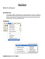
INTRODUCTION
Congratulations on your purchase of SSDCP. This manual is intended to give you
overviews of the various routines included in your selected package. This manual
includes information on the complete SSDCP package, so there may be information on
modules you did not purchase and were not a part of your purchase. Please use this
manual as a guide to help you, but nothing replaces actually trying a routine to see what
your options may be. The depth of SSDCP makes it impossible to cover each and every
question presented in each routine. A reminder that the online help system within SSDCP
contains the same information found within this manual.
SSDCP Manual
SSDCP Manual
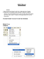
Installing SSDCP
These Installation instructions will lead you through the process of installing SSDCP from
scratch (onto a computer where SSDCP has never been installed before). It will also
show you how to make the necessary settings in AutoCAD. Consult your user manual for
uninstalling, updating, moving your license to a different computer, etc. An SSDCP
system consists of two parts – the SSDCP “license” and the actual programs themselves.
Your installation materials consist of a set of two pieces:
1. An SSDCP Installation CD + SSDCP License (on 3.5” Diskette) … or …
2. An SSDCP Installation CD + SSDCP License (on a USB Flash Drive)
These two are a set and you should keep them together. When you install, uninstall, or
do any other task that involves the SSDCP installation media, they are both inserted at
the same time starting with the License media (the diskette or Flash Drive).
The ‘license’ is in essence a security system that prevents you from installing SSDCP on
more than one computer at a time. If you wish to use SSDCP on more than one
computer, you need a Starter Modules (licenses) for each machine. You can move your
license from one computer to another, but can only be on one at a time (See the manual
section for transferring your license).
These two parts of SSDCP are installed in two steps: first the License, them SSDCP
itself (the programs). These steps are both done from the same screen.
PLEASE NOTE: Using SSDCP requires the user to have FULL ADMINISTRATIVE
RIGHTS on his or her PC. Please be certain you have Administrative rights before
attempting to install or use SSDCP.
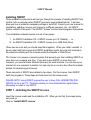
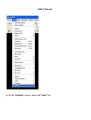
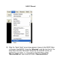
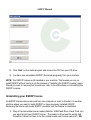
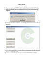
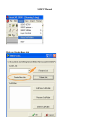
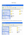
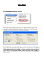
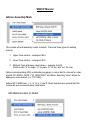
STEP 1 - Installing the SSDCP License
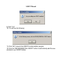
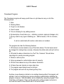
Insert the License media and the Installation CD. When you do that, the screen below
will come up.
Click on “Install SSDCP License”.
SSDCP Manual
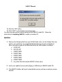
If the license installs successfully, you will see this message box:
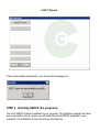
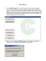
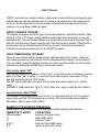
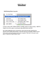
STEP 2 - Installing SSDCP (the programs)
Once the SSDCP license is installed in your computer, the installation program will allow
you to proceed to step 2 - where you will install the actual SSDCP programs in your
computer. The installation screen should now look like this:
SSDCP Manual
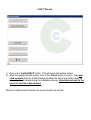
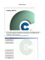
1) Click on the “Install SSDCP” button. This will launch the Installer wizard.
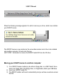
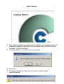
2) When the Installer Wizard is done, click on the “Finish” button to close it. Now wait
a few seconds while the Install Interface refreshes the screen and cleans up all the
temporary files it created during the installation process. Be patient and wait for the
screen to look like it does below!!
When the Install wizard is finished, the screen should look like this:
SSDCP Manual
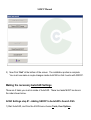
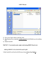
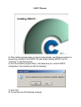
3) Now Click “Exit” at the bottom of the screen. The installation portion is complete.
You must now make a couple changes inside AutoCAD so that it works with SSDCP.
Making the necessary AutoCAD Settings
There are 2 tasks you must do inside of AutoCAD. These two tasks MUST be done in
the order shown below.
ACAD Settings step #1 - Adding SSDCP to AutoCAD’s Search Path
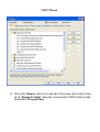
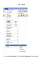
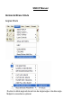
1) Start AutoCAD, and from the ACAD menu choose Tools, then Options.
SSDCP Manual
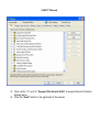
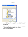
2) On the “Options” screen, select the “Files” tab.
SSDCP Manual
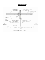
3) Click on the “+” next to “Support File Search Path” to expand the list of folders
already done.
4) Click the “Add” button to the right side of the screen.
SSDCP Manual
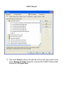
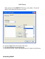
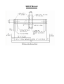
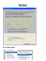
5) Click on the “Browse” button to the right side of the screen (above Add) to bring
up the “Browse for Folder” dialog box, and select then SSDCP folder (located
underneath C:\Program Files)
SSDCP Manual
6) Click the “OK” button. This will close the “Browse for Folder” dialog and return
you to the “Options” dialog showing SSDCP as being the last entry in the list of
search path folders.
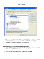
7) Click onto the “Move Up” button (on the right side of the screen) until SSDCP is
located just above the AutoCAD “Support” folder (see below).
8) Click the OK button at the bottom.
SSDCP Manual
9) If you are using Windows 98 or ME or AutoCAD R14, you must close AutoCAD
and restart your computer now. For Windows 2000 or XP, restarting the
computer is probably not necessary, but it couldn’t hurt.
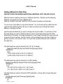
ACAD settings step #2 - Adding SSDCP to the AutoCAD menu
Once SSDCP has been added to the ACAD search path, you can run the script that will
insert SSDCP into the menu.
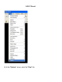
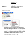
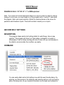
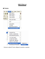
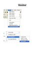
1) From the main ACAD menu choose “Tools” then “Run Script”
SSDCP Manual
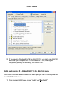
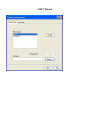
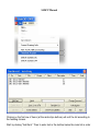
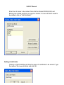
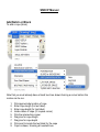
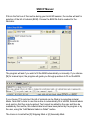
2) When the “Select Script” screen below appears, browse to the SSDCP folder
(c:\Program Files\SSDCP). Select the “Menuload” script file form the list. The
script name should be “Menuload” followed by the AutoCAD version you
specified for your install. I.e., the script for AutoCAD 2000 is called
“Menuload2000.scr” while AutoCAD 2005 is “Menuload2005.scr”.
SSDCP Manual
3) Click on the “Open” button to start the script.
4) After Menuload has completed, CLOSE and EXIT AutoCAD before you do anything
else.
5) Restart AutoCAD.
THAT’S IT !! You should now be ready to start using SSDCP. Good Luck.
Adding SSDCP to the AutoCAD search path
1) Start AutoCAD, and from the ACAD menus choose Tools, then Options.
SSDCP Manual
2) On the “Options” screen, select the “Files” tab.
SSDCP Manual
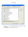
6) Click on the “+” next to “Support File Search Path” to expand the list of folders
already done.
7) Click the “Add” button to the right side of the screen.
SSDCP Manual
8) Click on the “Browse” button to the right side of the screen (above Add) to bring
up the “Browse for Folder” dialog box, and select then SSDCP folder (located
underneath C:\Program Files)
SSDCP Manual
6) Click the “OK” button. This will close the “Browse for Folder” dialog and return
you to the “Options” dialog showing SSDCP as being the last entry in the list of
search path folders.
10) Click onto the “Move Up” button (on the right side of the screen) until SSDCP is
located just above the AutoCAD “Support” folder (see below).
11) Click the OK button at the bottom.
SSDCP Manual
12) If you are using Windows 98 or ME or AutoCAD R14, you must close AutoCAD
and restart your computer now. For Windows 2000 or XP, restarting the
computer is probably not necessary, but it couldn’t hurt.
Adding SSDCP to the AutoCAD menu by Script
1) Once SSDCP has been added to the ACAD search path, you can run the script
that will insert SSDCP into the menu.
2) From the main ACAD menu choose “Tools” then “Run Script”
SSDCP Manual
3) When the “Select Script” screen below appears, browse to the SSDCP folder
(c:\Program Files\SSDCP). Select the “Menuload” script file form the list. The
script name should be “Menuload” followed by the AutoCAD version you
specified for your install. I.e., the script for AutoCAD 2000 is called
“Menuload2000.scr” while AutoCAD 2005 is “Menuload2005.scr”.
SSDCP Manual
4) Click on the “Open” button to start the script.
5) After Menuload has completed, CLOSE and EXIT AutoCAD before you do
anything else.
6) Restart AutoCAD.
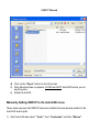
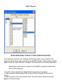
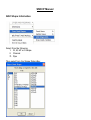
Manually Adding SSDCP to the AutoCAD menu
These steps assume that SSDCP has been installed and was already added to the
AutoCAD search path.
1) Start AutoCAD and select “Tools”, then “Customize” and then “Menus”.
SSDCP Manual
2) Click on the “Menu Groups” tab of the “Menu Customization” screen (below).
SSDCP Manual
SSDCP Manual
3) Click “Browse” to bring up the “Select Menu File” screen.
NOTE: At the bottom of the screen above, make sure that “is showing in the box labeled
“Files of type”. If it is not, open that list box by clicking the arrow and picking Menu
Template (.MNU)” from the list.
4) Assuming the Menu File screen is displaying .MNU files (see above note), you should
see an MNU file listed in the large white area of the screen. The file name will
correspond with the version of ACAD you are using. For example, above you see the
SSDCP2004.mnu meaning this install is for AutoCAD R2004.
5) Click onto the .MNU file, then click “Open”. This will start to install the SSDCP menu
group.
6) Click “Yes” when the dialog box below pops up asking if you want to continue loading
SSDCP Manual
SSDCP Manual
VIEW, and then click the INSERT BUTTON (at top, in the middle). This will add
SSDCP into the Menu Bar list shown on the right.
8) Press the “Close” Button at the bottom of the screen.
9) Exit AutoCAD before you do anything else.
10) Now Restart AutoCAD. SSDCP should appear as the 3rd option in the ACAD menu.
Uninstalling SSDCP
SSDCP Manual
NOTE: You do not need to put your SSDCP License medium in the computer in order
to uninstall SSDCP since it is already in your computer.
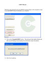
2) Click on the “Uninstall SSDCP” button. This will launch the Installer Wizard and
after several flashing screens display the confirmation screen (be patient):
3) Click Yes to continue.
SSDCP Manual
5) Click “Exit” on the Install program and remove the CD from your CD drive.
6) You have now uninstalled SSDCP (the actual programs) from your machine.
NOTE: The SSDCP license is still installed in your machine. That means you can reinstall SSDCP without having to do the process of “Installing the SSDCP License” again.
Should you want to remove your license now, refer to the instructions on Uninstalling the
SSDCP License.
Uninstalling your SSDCP license
An SSDCP license can be removed from one computer in order to transfer it to another
machine where you want to install SSDCP or have previously installed SSDCP.
Removing the license will render SSDCP unusable until the license is reinstalled.
1) Plug in the removable license media (diskette, USB Flash Drive, Flash Card, etc)
you want to hold your SSDCP license. The media or drive must be empty and
formatted. It does not have to be the original media your license came on). DO
SSDCP Manual
2) Put the SSDCP Install CD in the CD drive now. When the Install Program
comes up, it should have the “Remove SSDCP License” button enabled (see
below). On the screen shown below, both the “SSDCP License” and the “Install
SSDCP” buttons are grayed out - indicating that both are currently installed. The
install program reads your SSDCP system to check its state of installation. The
Installer Program only offers valid choices.
3) NOW … Click on “Remove SSDCP License”. If the license is transferred
successfully, you should see a message that looks like this:
SSDCP Manual
4) The Install program screen should now look like this:
5) Click on the “Exit” button. This will close the Install interface.
FOR FLASH DRIVES
For solid state drives such as USB Flash Drives, Flash Cards, Zip drives, etc., it is
recommended that the device be “prepared for removal” before removing or unplugging
it from your computer. This can be done by finding the icon in the system tray with the
popup label “Safely Remove Hardware” and clicking on it with the left mouse button.
This will bring up a small popup window that you click on to prepare the drive for safe
SSDCP Manual
When the following message appears it is safe to remove your drive, which now contains
your SSDCP license.
The SSDCP license is now located on the removable medium and is free to be installed
onto another computer. Or back onto this one.
LAST STEP: Remember to remove the SSDCP Install CD from the CD drive..
Moving your SSCP license to another computer
1) Your SSDCP license media may be either a floppy disk, or a USB “thumb” drive.
Insert your floppy disk in the floppy drive, or if applicable, attach your USB drive.
2) Insert your SSDCP install CD.
3) The SSDCP installer will launch automatically and you will see a welcome screen
like this:
SSDCP Manual
4) If the installer program does not launch automatically, use Windows explorer to
browse the contents of the SSDCP CD and double click the SSDCP icon for
“Launcher” to start the process.
5) You will be asked if you want to move your license:
6) Click YES.
7) You will be reminded to make sure your license media has been
inserted/attached:
SSDCP Manual
8) Once you verify your SSDCP license media is attached, click the “OK” button.
9) Once the necessary files are created and moved, you will see the following
message:
10) Click the “OK” button to continue. You will then see the license install & removal
program:
11) Click the “Remove SSDCP License” button to automatically copy and save your
license to the license media.
12) Once the license has been removed, you will see the following message:
SSDCP Manual
13) Click the “OK” button.
14) Click “EXIT” on the license removal program
You may now remove the license media and the SSDCP install CD. Follow the
instructions for Installing SSDCP to install on another PC.
Updates
1) Remove the following files from your ACAD folder (note: not all of these files may
exist in your machine). It is suggested that the files be moved to a diskette or
other removable media & then discarded after the 2005 update is installed:
a. ACAD.LSP
b. SETUP.LSP
c. SSDCP.MNU
d. SSDCP.MNL
e. SSDCP.MNC
f. SSDCP.MNS
g. SSDCP.MNR
h. Any other files that contain SSDCP in their name.
2) Insert your update license media (floppy or USB drive) & SSDCP install CD.
3) The SSDCP installer will launch automatically and you will see a welcome screen
like this:
SSDCP Manual
4) If the installer program does not launch automatically, use Windows explorer to
browse the contents of the SSDCP CD and double click the SSDCP icon for
“Launcher” to start the process.
5) You will then see the license installer program start:
SSDCP Manual
BUYING AND INSTALLING ADDITIONAL SSDCP MODULES
You may purchase additional SSDCP modules at any time and add them to your existing
SSDCP modules. To purchase additional modules, simply call SSDCP and place your
order!
SSDCP will send an executable file via email, or if you chose, via regular postal service
mail.
Once you have the executable file (named either “FeatureInstaller2005” or
“FeatureInstaller2005.exe”).
1) Simply double click the icon for the executable file. You will see the following message
once the program successfully runs:
2) Click the “OK” button to exit.
3) Insert your SSDCP install CD.
4) The SSDCP installer will launch automatically and you will see a welcome screen like
this:
SSDCP Manual
5) If the installer program does not launch automatically, use Windows explorer to
browse the contents of the SSDCP CD and double click the SSDCP icon for
“Launcher” to start the process.
6) Once the installer program starts, it will determine your current SSDCP
configuration, then prompt you with the following:
7) Click “NO”
8) You will then see the following message:
SSDCP Manual
9) Click “Yes”
10) You will see the following:
11) Click “OK” to launch the SSDCP module installer program
12) Click the “REPAIR/REINSTALL SSDCP” button to automatically add the new
modules to your SSDCP station.
SSDCP Manual
SSDCP Manual
SSDCP SETUP
PLEASE NOTE: Using SSDCP requires the user to have FULL ADMINISTRATIVE
RIGHTS on his or her PC. Please be certain you have Administrative rights before
attempting to install or use SSDCP.
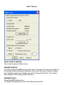
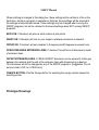
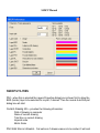
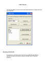
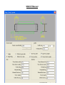
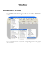
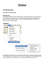
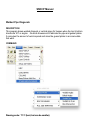
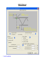
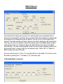
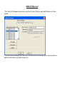
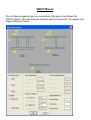
Using SSDCP setup to start a drawing
After selecting SSDCP setup from the menu, a standard "Save As" dialog box
will be shown. Save the name of the drawing in the same manner as any other
AutoCAD drawing.
SSDCP Manual
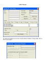
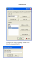
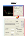
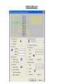
SELECT SSDCP VERSION:
Select either Imperial or Metric version.
DRAWING PROFILE:
This area contains the LAST drawing profile used. If this sheet is the same information as
the last and all other information is the same, click on the OK button at bottom of dialog
box. If anything needs to be changed, click on the Change Profile button. This will then
allow changes to the drawing profile information.
DRAWING SCALE:
Shows the LAST drawing scale.
To change the drawing scale, click on the Change Scale button.
SSDCP Manual
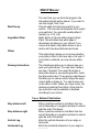
When anything is changed in this dialog box, these settings will be written to a file on the
hard drive. Anytime a program is cancelled or finished, these settings will be returned to
the settings as selected and saved. These settings may be changed when running the
SSDCP programs, but will be returned to the saved settings when NOT running SSDCP
programs.
BLIPS ON: If checked, will place a small marker at pick points.
SNAPS ON: If checked, will turn on your snaps to whatever increment is selected.
ORTHO ON: If checked, will set crosshair to 0 degrees and 90 degrees movement only.
FORCE DIM INSIDE EXTENSION LINES: If checked, this will force all dimensions inside
of extension lines.
OFFSET EXTENSION LINES: A "REAL WORLD" dimension can be entered if a little gap
between the material and the end of the extension lines with dimensioning is desired.
This dimension will not be changed by any of the SSDCP programs. (Suggestion: Do not
set more than 0.0313 or 0.79502 mm)
OSNAPS BUTTON: Pick the Osnaps button for selecting the osnap controls desired for
selecting points.
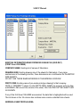
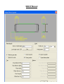
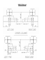
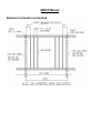
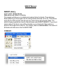
Prototype Drawings
SSDCP Manual
EXISTING INFORMATION READ FROM DATA BASE FILE (SSD.DAT)
(FIRST three COLUMNS)
COMPANY NAME: Existing list of names of fabricators.
DRAWING SIZE: Existing drawing size of the sheets for fabricators. If very large
numbers are in the drawing size box, those dimensions are in millimeters for the METRIC
SIZE SHEETS.
DO NOT USE THESE WHEN WORKING IN THE IMPERIAL VERSION.
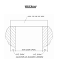
PROTO DWG: Existing name of pre-made prototype drawing for that company.
NOTE: If "BORDER" is shown for the PROTO DWG. NAME, the program will only draw
a BORDER LINE around the outside of the sheet, CALCULATED ON THE SHEET SIZE
AS SHOWN.
If any of the first three COLUMNS are selected, the data that is highlighted will be used.
The list shown in the 1st column also contains some common standard size sheets.
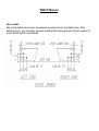
ADDDING A NEW PROFILE AREA
SSDCP Manual
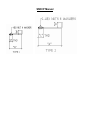
DRAWING SIZE: a drawing size MUST be entered for the NEW PROTO DWG. Enter the
size
by HEIGHT then WIDTH.
(EXAMPLES: (IMPERIAL: 11x 8.5, 24x36, etc.) ( METRIC 210x297, 594x841, etc.)
NOTE: If working within the metric version, a standard Imperial size sheet can be used.
The program will convert the dimensions entered to millimeters. (EXAMPLE: enter 24x36.
The sheet size will be changed to 610x914.)
PROTO DWG: a FULL SIZE prototype drawing must be drawn to represent the new
fabricator’s sheet. If the name of the new fabricator’s prototype drawing is not known,
leave this box blank. This will then only draw a border line around the outside of the sheet
and the proto drawing will have the fake name of border. This does not actually make a
drawing called border.dwg. (the proto dwg. name cannot be longer than eight characters)
DELETE CURRENT PROFILE BOX:
This is the list of the current selected company names as highlighted in the dialog box.
Selecting the item to delete, and then pressing the delete profile button will delete the
names from the dialog box. Never delete all the names from the list. At least one
company name in the list be listed. Do not delete the company name called "SSDCP" or
"SSDCPM". These are standard shop drawings that are included with the SSDCP
package.
SSDCP Manual
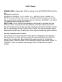
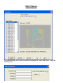
Selecting Drawing Scales
EXPLANATION OF DRAWING SCALES
SELECT the scale that desired for the drawing. Notice that this is a combination of scales
for both IMPERIAL and METRIC versions. When selecting a scale, the program will only
input the corresponding DIMSCALE value into the program. If working in the IMPERIAL
version a corresponding value for IMPERIAL. (Ex. 1" = 1'-0) must be selected.
If working in the METRIC version, either IMPERIAL or a METRIC scale may be selected.
The dimscale values are listed in decending order. NOTE: As the DIMSCALE VALUE
decreases the SCALE value increases.
After a scale has been selected, click on the “OK” button.
SSDCP Manual
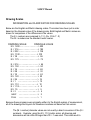
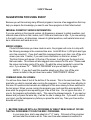
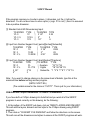
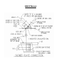
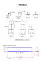
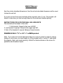
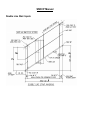
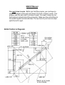
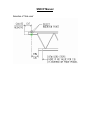
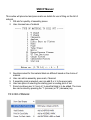
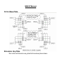
Drawing Scales
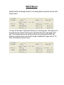
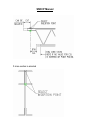
INFORMATION and CLARIFICATION FOR DRAWING SCALES
Below are the English and Metric drawing scales. The scales have been put in order
based on the dimscale value of the drawing scale. Both English and Metric scales are
shown for comparison of the differences in the values.
The E = numbers are compared to 1'- 0. (Ex. 1/8 to 1'- 0)
The M = numbers are the standard metric scales.
DRAWING SCALE
DIMSCALE VALUE
M = 1:200 - - - - - - - - - - - - - - - > 200
E = 1/16 --- - - - - - - - - - - - - - - > 192
E = 3/32 - -- - - - - - - - - - - - - - > 128
M = 1:100 - - - - - - - - - - - - - - > 100
E = 1/8 - - --- - - - - - - - - - - - - > 96
M = 1:75 - - - -- - - - - - - - - - - - > 75
E = 3/16 - - - - - --- - - - - - - - - - > 64
M = 1:50 - - - - - - -- - - - - - - - - > 50
E = 1/4 - - - - - - - - --- - - - - - - > 48
E = 3/8 - - - - - - - - - - --- - - - - > 32
E = 1/2 - - - - - - - - - - - - --- - - > 24
M = 1:20 - - - - - - - - - - - - - - - > 20
E = 3/4 - - - - - - - - - - - - - - -- > 16
E = 1 - - - - - - - - - - - - --- - - > 12
M = 1:10 - - - - - - - - - - - -- - - > 10
E = 1 1/2 - - - - - - - - - - - - - -- - > 8
M = 1:5 - - - - - - - - - - - - - - -- > 5
E = 3 - - - - - - - - - - - - ---- - - > 4
HALF - - - - - - - - - - - -- - - - > 2
FULL - - - - - - - - - - - - -- - - > 1
Because these programs were originally written for the English system of measurement,
all of the drawings and layouts for dimension locations are based on that version.
The (M = number) dimscale values are not exactly a direct conversion of the (E =
numbers). Example: using the M = 1:10 (metric scale), all drawings and
dimensions will be a little bit larger than if E = 1 was used. This could result in
SSDCP Manual
All main programs (beams, columns, bracing, stairs, handrail, etc.) were written to be
drawn at a 1"=1' scale.
When you pick the drawing scale from the sidebar menu, the only item entered into the
computer is the DIMSCALE NUMBER. It makes no difference which version you are
working in.
Based on the above information, if the E = numbers are used when working in the Metric
System, all drawings will look much better because the programs were written to use the
English system of measurement.
SSDCP Manual
Using DWT Templates
A "standard" sheet with scale and title block filled in can be made and any notes desired
on that sheet. Then save this sheet with a .DWT (template name extension). Consult your
AutoCAD manual or the help files about this for more information. This is a very good
feature and can save a lot of time and trouble.
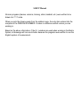
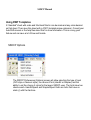
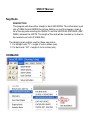
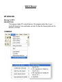
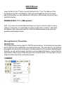
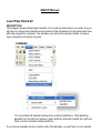
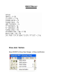
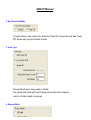
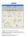
SSDCP Options
The SSDCP Preferences (Options) screen will allow selecting the type of input
(CVS style or Numeric style), the choice of font (Handltr or Simplex) and the
ability to set the choice of colors for the layers SSDCP uses. The fonts have two
choices each. Handltr/Spec2 and Simplex/Spec2 both are fonts that have no
slash (/) with the fractions.
SSDCP Manual
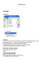
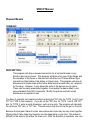
SSDCP UTILITIES
Plot – when this is selected the Layers Properties dialog box is shown first to allow the
BOR (border) layer to be selected for no-plot, if desired. Then the normal AutoCAD plot
dialog box will start.
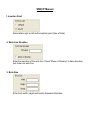
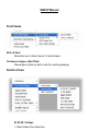
Current drawing info – provides the following information:
Path of drawing on computer
Name of current drawing
Total time on current drawing
Imperial scale
Metric Scale
Print total time on drawing - first option is if drawing name is to be printed. It will print
SSDCP Manual
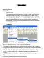
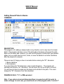
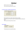
Timesheet Program
The Timesheet program will keep up with time on a job based on any or all of the
following items:
1. Date
2. Drawing Name
3. Project or Job Number
4. Client's name
5. Time on drawing for any editing session
6. By description of work done (ex. – detailing, revisions, approval changes, etc.)
7. By any code for any type of detailing (ex. – BM for beams, COL for columns,
etc.)
It can be customized with custom code names or numbers.
The program also has the following features:
1. Will make an invoice based on any of the items above. The text style cannot
be changed for making these invoices, otherwise the dollar and cents will not line
up.
2. Will write the above information to a "text" file, if desired. This will allow
importing into a word processing program.
3. Delete or edit any item
4. Setup a password or authorization name for security
5. Will sort items based on any of the above information
6. All items have an internal on screen help item.
7. The program uses dialog boxes for all input.
8. The program will work on any drawing at any time,
Anytime a new drawing is started or an existing drawing edited, this program will
operate. It will not recognize any previous drawing created before installing the
program. However, this information can be obtained by using the program "Print
Total Time on Drawing". Then use the edit portion of the program and enter in
the total time spent on this drawing as of the current date.
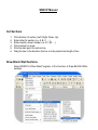
SSDCP Manual
Clicking on the first row of items (at the radio style buttons) will sort the list according to
the heading chosen.
Start by clicking "Add Item". Then to enter text in the textbox below the main list in order
SSDCP Manual
To include any heading on an invoice, click the desired checkbox. Choose either "rate" or
"fee" for your project.
SSDCP Manual
The first time this is used, enter "." as your authorization code.
Error Screen ON – turns the error screen on
Error Screen OFF – turns the error screen off
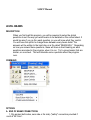
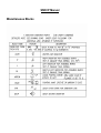
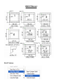
LAYER CONTROLS
Change entity to another layer – click on any existing entity (multiple can be selected)
and then choose an entity that is on the layer desired. This will change the selected
entities to the layer selected.
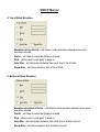
Change current layer to:
OBJ – dimensions and notes layer
FS – far side objects layer
BOR – nodes layer
HL – heavy line (for main members) layer
FSH – far side hidden lines layer
LL – User defined items layer
CNTR – centerline layer
JOIST – bar joist layer
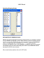
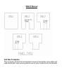
SETUP JOB FOLDERS
In an effort to give some structure to the file system within SSDCP and to aid in future
enhancements, this Jobs Folders Program has been developed. In the past when
detailing bracing, a file was written to your SSDCP folder, but was not job specific. Now,
a Jobs Folder for any job can be created. For example, if a Job Folder with a name of
NCJob1 was created and added some bracing, those files your be written to the Bracing
Sub-Folder under the NCJob1 folder. Then when the next job is created, another set of
sub folders will be created, with empty folders. So what is done within one job does not
affect another.
In order to run this, click SSDCP then “Setup Job Folders". A dialog box allows the job
folders to be setup as well as the option to make sub folders.
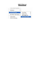
SSDCP Manual
Click on Create New Job
SSDCP Manual
Enter the Job name to be created. Note that the folders DWGS, BOM, and
Bracing are created each time a new job is started. If a new sub-folder needs to
be created, click on "Add Subfolder".
Adding a Sub-Folder
Clicking on Add Subfolder will allow the name of a subfolder to be entered. Type
the name of the new sub-folder and click OK.
SSDCP Manual
The new sub-folder is now in the list of sub-folders that will be created under the
main Job folder.
Renaming A Sub-Folder
To rename any sub-folder (other than the three locked standard folders),
highlight the name of the folder to rename, and then click on "Rename
Subfolder".
SSDCP Manual
A dialog box will allow you to change the folder name.
Enter the change and click OK.
SSDCP Manual
The sub-folder list now reflects the change. Sub-folders can be deleted in the
same manner, by highlighting them and then clicking "Remove SubFolder".
The new Job Folder now is located under the “My Documents” folder.
SSDCP Manual
The selected sub-folders have now been created under the main job folder.
SSDCP Manual
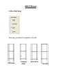
SSDCP provides three custom toolbars to help select commands that are frequently used
without having to use the pulldown menus or type in the command on the keyboard. Do
not try to use the big buttons for these toolbars. All standard AutoCad commands for
resizing or moving these toolbar will apply.
SSDCP STANDARD TOOLBAR:
This toolbar will appear across the top of the screen whenever AutoCad is started. There
will be a "TOOL TIP" shown, stating what that button does when the pointer is over the
selected button. Some of these buttons are a single button and some of them are "flyout"
buttons. Hold the button down to see the rest of the flyout button choices. These buttons
are the same as the standard AutoCad buttons. Some of the buttons are standard
AutoCad commands and some are for the SSDCP programs.
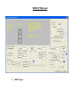
SSDCP DIMENSIONING TOOLBARS:
There are two vertical toolbars located on the right hand side of the screen. These will
help entering numbers or dimensions into the programs without typing on the keyboard.
Once you have chosen the buttons to enter, you must move the pointer out of the button
area before pressing the ENTER key or clicking the mouse.
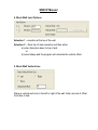
First toolbar called "NO"
This toolbar has whole numbers in it from 0 to 11. From this column of numbers, you may
enter a number, feet, or inches. You will also find a decimal point, minus sign, Ft sign,
and a @ sign button and a "YES" button.
The "@" sign is used when you want to draw a line at a certain length, at a < certain
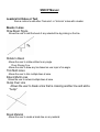
angle.
(EXAMPLE: LINE command, @ 2'-0 < 22.5) (Note: the < sign in under the frac toolbar.)
Second toolbar called "FRAC"
This toolbar is for entering fractions of an inch. You will notice that the 1/4" increments
are in green, and the 1/8" increments are in yellow. This makes finding the numbers a
little easier. There is also a "NO" button.
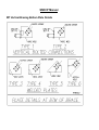
EXAMPLES FOR ENTERING DIMENSIONS:
Remember to move the pointer out of the toolbars before pressing the enter key.
DIMENSION TO ENTER
PICK BUTTON
Whole number
button(s) of choice (enter)
¾"
button 3/4, (enter)
6"
button 6, (enter)
6 5/16"
button 6, button 5/16 (enter)
9'-0
button 9, button FT (enter)
SSDCP Manual
120'-10 15/16
15/16 (enter)
button 1, button 2, button 0, button FT, button 10, button
If you choose the "Y" (YES) or "N" (NO) button for answers to the questions in the
programs, these will be entered with no further key strokes.
SPECIAL INFO ON MENUS ONLY FOR ALL THE WINDOWS VERSIONS:
If you make a custom change in the SSDCP.MNU menu file, you must erase the
following files to put these changes into effect.
1. SSDCP.MNS
2. SSDCP.MNC
3. SSDCP.MNR
If you make some custom toolbars, you must copy the code pertaining to the custom
toolbars you have made from the SSDCP.MNS and put this into the SSDCP. MNU, then
erase the above named files. Do not attempt to do this unless you have some experience
in changing menus.
CUSTOMIZING TOOLBAR BUTTONS
You can only create one button at a time. All the SSDCP menu files must be in the same
directory as the ACAD menu files:
SSDCP.MNU, SSDCP.MNS, SSDCP.MNC, SSDCP.MNL AND SSDCP MNR.
Check the name of the menu group
1. Pick TOOLS from top bar menu.
2. Go to "Customize Menu"
3. Under FILE make sure name is ACAD. If not, change to ACAD.
4. Close menu customization dialogue box.
TO CREATE NEW PALETTE TO PUT BUTTONS IN:
1. Pick TOOLS from top bar menu.
2. Pick "Customize Toolbar".
3. Click on NEW. (New TO0LBAR dialogue box will appear.)
4. Under toolbar name, enter any name you want. (Ex. MYTOOLS)
5. Click on O.K.
SSDCP Manual
TO CREATE A CUSTOM BUTTON:
1. Pick TOOLS from top bar menu.
2. Pick "customize toolbars".
3. Arrow down to "ACAD.MYTOOLS"
4. Pick customize button.
5. Under "categories", select "Custom".
6.Click & Drag the single "blank" custom button to your "palette picture".
7. Use enter button on mouse and pick blank button in your palette.
Wait for the button properties dialogue box to appear. It may take a few seconds.
8. In name box, enter NEW NAME for button. (Ex. MYBUTTON) This will appear as the
"Tool Tip" when you point at the button.
9. Type any message in the help box to describe what this button will do. This message
will be printed below the command line area.
10. Under MACRO, enter command for whatever you want the button to do when
chosen.
See Autocad Manual for instruction how to enter macros.
11. Note: You can chose any "Predrawn Icon" from the Button Icon Box or you can click
on the
"Blank" button and create your own. See AutoCad manual for further instructions on how
to do this.
12. Pick APPLY button.
13. Close all dialogue boxes.
14. The button in the palette box should be updated to show the picture and should work
when chosen.
TO ADD EXISTING BUTTONS TO YOUR PALETTE (MY TOOLS)
1. Pick TOOLS from top bar menu.
2. Pick "customize toolbars".
3. Pick ACAD.MYTOOLS
4. Pick customize button.
5. Under categories, pick desired command section. (Ex. Draw)
6. Pick desired draw icon and drag to "MYTOOLS" PALETTE.
7. Close the dialogue box.
TO EDIT EXISTING BUTONS
If you want to edit an existing button or flyout, you can go directly to either the Button
Properties or the Flyout Properties dialog box by double right clicking on a button. Once
SSDCP Manual
You may add as many standard buttons to the "my tools" palette as you wish. You need
to plan ahead and draw a simple picture of the buttons you want in this palette before you
start. Also work out the MACROS that will control what this button does before you start.
We recommend that you initially create only one custom "palette" with one custom
"button" in it until you see how all this works. When this is done, "EXIT" AutoCAD and
then "RE_ENTER" AutoCAD to make sure your custom palette and button is still there
and it works. You can always add to this palette later. See the "customization " AutoCAD
manual for more help. Once you have created one button and it works, you can easily
create any custom toolbars you wish.
SSDCP Defined Functions
The following is a list of defined functions used within SSCDP. If you have a "Custom"
ACAD.LSP program, do not duplicate any of these DEFUN names. If you have a
duplicate name and want to know the function of a DEFUN that is duplicated, contact
SSDCP.
DEFUN _M
DEFUN CLRSCR
DEFUN SPC
DEFUN IN
DEFUN FLASH
DEFUN DTR
DEFUN OBJ
DEFUN BOR
DEFUN FSH
DEFUN LL
DEFUN TZ
DEFUN VDIS
DEFUN EDFN
DEFUN BA
DEFUN HY
DEFUN YNN
DEFUN LOTQ
DEFUN RBOLT
DEFUN BOLTZA
DEFUN ADDNUM
DEFUN SMS
DEFUN WELD
DEFUN DWS
DEFUN STXT1
DEFUN STXT2
DEFUN HGET
DEFUN _ROT
DEFUN _TIMER
DEFUN DIMD
DEFUN REALD
DEFUN YND
DEFUN CLA
DEFUN DIMLINE
DEFUN C:H
DEFUN C:A
DEFUN C:B
DEFUN C:GET
DEFUN BELL
DEFUN 2SPC
DEFUN OUT
DEFUN WARN
DEFUN _RTD
DEFUN FS
DEFUNHL
DEFUN CL
DEFUN JOIST
DEFUN HDIS
DEFUN _SDFN
DEFUN TAN
DEFUN RI
DEFUN YN
DEFUN BC
DEFUN BCHG
DEFUN WBOLT
DEFUN BOLTZ
DEFUN STXT5
DEFUN SEC
DEFUN WELD1
DEFUN STXT
DEFUN STXT4
DEFUN STXT3
DEFUN ROT
DEFUN _GETIME
DEFUN INTD
DEFUN DDD
DEFUN STRD
DEFUN MYCK
DEFUN CNTR
DEFUN C:V
DEFUN C:C
DEFUN C:R
SSDCP Manual
SUGGESTIONS FOR USING SSDCP
Because you will be learning many different programs, here are a few suggestions that may
help you acquire the knowledge you need to use these programs to their fullest extent.
IMPERIAL OR METRIC VERSION INFORMATION:
If you are working in the imperial version, all dimensions, answers to global questions, and
material sizes must be in feet, inches, and 1/16ths and loads are in kips. If you are working
in the metric version, all dimensions, answers to global questions, and material sizes must
be in millimeters and loads are in kn.
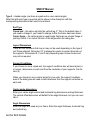
ERROR SCREEN:
If AutoCAD determines you have made an error, the program will come to a stop with
the following message in the command line area. AutoCAD Error = (Will print what type
error has occurred.) If you don't want this message shown every time, turn off the error
screen (see note 1. below). If you want more information on this error, answer "Y".
The Error Screen will appear. At the top of the screen, it will give you the type of error
that was made. This screen will also suggest some reasons for this error. Please read
the screen and make a note of the error. Do what the screen suggests to correct the
error. If you answer "N": "END OF PROGRAM" and you will have to try again.
NOTE 1.: If you don't want this question asked every time, turn off the error
screen as listed in the pull down menu under "SSDCP/SSDCP Utilities".
COMMAND AREA ON SCREEN:
You will see three lines of text at the bottom of the screen. This is the command area. This
area tells you what is required when running the programs. You must pay close attention to
this area. All questions and remarks are displayed in this area unless you have switched to
the text screen. When you are running the programs you must read this area carefully to
know what the programs are requesting you to do at that time. Do not ignore this area. If
you do, the programs will probably crash. This cannot be stressed enough. If you input an
answer and you press the enter key, it will be too late to change this. If you want to correct
your input, use the backspace key before you press the enter key. Take your time and be
accurate with inputs.
1. BECOME FAMILIAR WITH ALL PROGRAMS IN TABLET MENU AREA #1 OR USE
THE PULL DOWN MENU TO RUN THE MISC. PROGRAMS.
In your spare time, start a new sheet at a 1"=1' scale. Pick each of the programs
and see what the program will do. Take your time when answering questions or
SSDCP Manual
2. IF YOU HAVE PURCHASED THE MISC. DRAWINGS IN PULLDOWNS:
Use the SSDCP Library choice under SSDCP PULL DOWN and insert each of the
blocks on your sheet. See what it will draw. Some of these blocks are for erection
drawing scales (1/8 or 1/4) and some are for detail sheet scales. (1"=1') Try to
remember what these blocks can draw for you. You can insert the block, then try
changing the dimensions and/or picture for practice. Use all of the change or modify
text programs [F- 6] [F- 7] [H- 23] [H- 24] [H- 25] on the digitizer (or listed in the pull
down menus) so you can see how they work. You can also add your own blocks to
these library files. See more instructions in the manual to do this.
3. USE THE "DRAW SECTIONS THRU" PROGRAMS
Pick different steel sizes to draw sections thru using the dialog boxes. This will teach
you how to draw sections thru steel sizes and work these lisp programs. Utilize all
choices of questions asked in programs so you can understand all the things the
program will do. Run each of the programs several times with different inputs and
sizes.
4. If you are running a program that has the "AUTOMATIC GLOBAL QUESTIONS"
appear on the screen when you first run the program:
Enter the line number for each line to change, so you can understand what these
changes will affect. Sometimes, the answers will just change automatically without
asking any more questions. This will apply for "yes" or "no" answers more often than
not. Sometimes, the way you answer a question will prevent or automatically change
some of the other global questions because they are logical conclusions based on
the first change. After you have made all the changes to a particular set of global
questions, they will be written to a file. They will be read from this file the next time
you run this program in the future. This can save a lot of time by not having to go
through all these global questions every time you start a new sheet of details.
5. WORK ALL OF THE CALCULATOR PROGRAMS
Use all choices for all programs.
6. USE THE DIMENSIONING PROGRAMS ON DIGITIZER OR IN PULLDOWNS
Practice using dimensions on your drawings. Use all the choices - vertical,
horizontal, continue, aligned, rotated and leader lines. Because we use the
SSDCP stacked fraction style, these are LISP programs, not the standard way
that AutoCAD dimensions. You will find these programs will work better and give
more dimensions than is available from AutoCAD.
SSDCP Manual
Try using different answers to the global questions to detail different ways. If you
mainly detail for only one fabricator, once you have set most of the global questions,
you will probably never change these global questions again. Use all options of the
global questions to draw different pictures and to use all of the program capabilities.
After you have used all of the options you can eliminate some of the options by
resetting the global questions not to draw some of the details. Unless you use these
options, you will not be fully aware of what all these programs can draw. Again, take
your time when answering the questions and entering dimensions. The program will
do whatever you tell it to do. While you are using these programs, try to think what
other things this program could do by "fooling" the program. EXAMPLE: You will
find when running the programs that the programs will request a dimensional input.
Normally, this input will be a positive (+) input. If you put a minus (- ) in front of the
input, then the opposite effect will occur when the item is drawn. You will just have to
play with this a little bit to really understand what will happen when the item is drawn.
This shows the flexibility of using a combination of the programs with AutoCAD.
Run each of the programs several times using different setup and material sizes,
dimensions and options. After you have a sheet of details complete, use some of the
minor programs (tablet area #1 or in pull downs) to add misc. pieces to your shop
pieces for practice. Practice putting assembly marks on your details and weld
symbols. Once you have completed your sheet, try plotting the sheet. Don’t forget to
turn off the "BOR" layer (green color) before you plot the sheet. This is for temporary
information only.
IMPORTANT REMINDERS
DRAWING PROCEDURE
Detail ALL horizontal & vertical bracing for the job, FIRST. This will write the
information about the BRACING PLATES to the hard drive, so you may very easily draw
the bracing plates on your beams or columns.
BEFORE PLOTTING A DRAWING:
1. ZOOM "ALL" of the drawing.
2. TURN OFF the "BOR" LAYER. (Color Green on the Drawing)
This layer is only for temporary information and misc. text. You do not want to plot this
SSDCP Manual
4. Plot drawing to whatever scale you made the drawing to. (Ex. 1"=1')
5. If you are going to have someone else plot these drawings, they need to know
these facts.
SENDING YOUR DRAWINGS TO SOMEONE ELSE:
You may in the course of doing business, need to send a drawing file to some other
person. Because of the fact that we are using the SSDCP text style in our drawings, they
may or may not have the special shape files required to print the text on the drawings in
their computers.
You must send the following three files for the text. Copy these three files to the disk
along with the drawings you are sending them.
1. SIMPLEX.SHX
2. SPEC.SHX (For stacked fractions)
3. HANDLTR.SHX (Special shape file for hand lettering style)
You will also need to tell them to copy these three files into their AutoCAD directory,
before loading the drawings. Otherwise AutoCAD will tell them it can’t find these shape
files. You will only have to do this the first time you send them drawings. Just tell them
not to erase the THESE .SHX FILES when they get through.
They will not have the SSDCP.mnu file that has been assigned to these drawings. When
they try to load these drawing, AutoCAD will tell them that it cannot find the SSDCP.mnu.
just tell them to load whatever menu file that they normally use. (ex. acad.mnu) Do not
send the SSDCP.mnu file to them because it won’t work.
If they are going to do any modification to the drawings, they will also need to know how
to use the "special" control keys for entering "fractions". You could send them a copy of
this page and a copy of the page in the manual explaining these key sequences and how
to change to the SSDCP text style. The "SSDCP" text style must be the "current" style
when modifying these drawings.
ENTERING DIMENSIONS (IMPERIAL)
CHOICES FOR ENTERING DIMENSION IN IMPERIAL VERSION ONLY
Note: This does not apply to the metric version. All inputs must be in millimeters.
SSDCP Manual
If the program requires you to enter a minus (-) dimension, put the (-) before the
dimension. You do not ever have to enter a plus (+) sign. If it is not (-) then it is assumed
to be a positive dimension.
[1] Standard AutoCAD Dimensioning Input:
TO ENTER TYPE | TO ENTER
10'- 0
10'
| 3 1/4"
10'- 3 ½
10'3.5 | 3"
10'- 3
10'3
| 1/2"
TYPE
3.25
3
.5
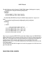
[2] Input from Number Keypad: Feet [.period][Inches][Sixteenths]
TO ENTER
TYPE
| TO ENTER TYPE
10'- 0
10
| 3 1/4"
.0304
10'- 3
10.03
| 3"
.03
10'- 3 ½
10.0308 | 5/16"
.0005
[3] Input from Number Keypad: Feet [-dash][Inches]*[Fractions]
TO ENTER
TYPE
| TO ENTER
TYPE
10'- 0
10| Quarters
*14 *12 *34
10'- 3 ½
10- 3*12 | Eights
*18 *38 *58 *78
3 1/4"
3*14
| Sixteenths *1 *3 *5 *7 *9 *11 *13 *15
3"
3
Note: If you want to change choices on the same sheet of details, type this at the
command line before running another program.
(SETQ CVSCT NIL)
(The variable name for the choice is "CVSTY". This is just for your information.)
CONVERTING CVSpro DRAWINGS TO SSDCP STANDARDS
If you have dxfin a CVSpro drawing into AutoCad and you want all of the SSDCP
programs to work correctly on this drawing, do the following:
1. At the bottom of the SSDCP pull down, click on "RESET LAYERS AND DIMVARS".
This will add the layers, dimvars and text style to the CVSpro drawing using SSDCP
programs
2. Then click on "CONVERT CVS DRAWING" and follow the directions on the screen.
This will convert the dimensions and styles to ensure all the SSDCP programs will work.
SSDCP Manual
Adding Material to Data Files
INSTRUCTIONS FOR ADDING ADDITIONAL MATERIAL INTO THE DATA FILES
Material sizes for detailing steel are in 2 different data files. The files are the following:
Data file for Imperial size steel: SSDCP1.DTA
Data file for Metric size steel: SSDCP2.DTA (Includes Canadian and German)
You must use a text editor to access the data file. You must work with an editor that will
read and write ASCII text files. Be sure to make a backup copy of these files before
adding or changing the files.
Load the selected data file you want to change into the text editor. You will have to find
the area where you want to add the sizes you want. These dimensions are the detail
dimensions of the steel, not design dimensions. Look through the data file to give yourself
a sense of how it is written. Use the "syntax" of the existing lines in the files to help you
get the numbers in the correct order. You must have a space between each number in
the data lines.
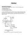
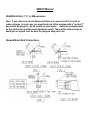
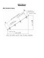
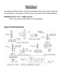
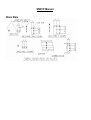
The data fields are read as follows for W, HP, M, S shapes:
[depth] [flg width] [flg thk] [web thk] [k dist] [flg gage] [Size]
EXAMPLE:
("W5"
(5.125 5.000 0.4375 0.25 0.75 3 "W5x19")
(5.000 5.000 0.3750 0.25 0.75 3 "W5x16")
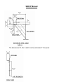
The data fields are read as follows for C & MC shapes:
[depth] [flg width] [flg thk] [web thk] [k dist] [flg gage] [Size]
EXAMPLE:
("C5"
(5 1.875 0.3125 0.3125 0.75 1.125 "C5x9")
(5 1.750 0.3125 0.1875 0.75 1.000 "C5x6.7")
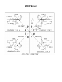
The data fields are read as follows for PIPE (standard, x-strong, dbl x strong & big pipe
shapes):
[outside diameter] [wall thickness] [weight] [size]
EXAMPLE:
("P"
("STD. PIPE"
SSDCP Manual
The data fields are read as follows for TUBE STEEL shapes. (Rectangular or square):
[longside] [short side] [wall thickness] [weight] [size]
EXAMPLE:
("TS 2.5"
(2.5 2.5 0.2500 7.11 "TS 2- 1/2x2- 1/2x1/4" )
(2.5 2.5 0.1875 5.59 "TS 2- 1/2x2- 1/2x3/16")
The data fields ARE READ as follows for ANGLE shapes (same for = legs or not =
legs):
[long leg] [short leg] [thickness] [k dist][weight] [y dist] [x dist] [size]
EXAMPLE:
("L"
("= LEGS"
(1.00 1.00 0.1875 0.2500 0.80 "1x1"
(1.25 1.25 0.2500 0.4325 1.92 "1- 1/4x1- 1/4")
(1.50 1.50 0.2500 0.3750 2.34 "1- 1/2x1- 1/2")
(1.75 1.75 0.2500 0.5000 2.77 "1- 3/4x1- 3/4")
(2.00 2.00 0.3125 0.6250 3.92 "2x2"
)
)
Note: If you are using the SSDCP2.DTA (metric file) for Metric sizes, the TUBE STEEL &
ANGLE dimensions must be entered in decimal inches, but the size must be entered as a
Metric size. The programs will convert these dimensions to millimeters and kilograms for
weight purposes, but the program and dialog box will use the Metric Size for the
description of the section. For all other steel sections, the dimensions and sizes must be
in the metric system.
The size field in the data field for angles is not used in any program, but it still has to be a
part of the data field.
SELECTING STEEL SHAPES
SSDCP Manual
NOTES PERTAINING TO SELECT STEEL SHAPE DIALOG BOX
This dialog box as shown is for selecting a Wide Flange beam, as an example. This
dialog box will be shown when required by any SSDCP program. The box shown will also
apply to channels, pipe, tube steel, or angles. This same occurs for all metric steel sizes.
Depending on what section is required in the SSDCP programs is what will be
shown in the dialog box.
1. The first column will show the "shapes" that is required by the program.
2. When you pick a shape required, the choices of sizes will appear in the second
column.
3. When you pick a size in the second column, the exact sizes of all the choices will
appear in the third column.
SSDCP Manual
When all the columns are highlighted for the section you want, click on the OK button.
Before picking the OK button, you can select a different size if you have a change of
mind.
The section chosen will be highlighted as the "default" the next time that the program
requires you to select the same shape as before. This will occur over different type of
shapes. If the shape that is highlighted is the same, just press the enter key or click on
the OK button.
The names of the files that contain the data for steel sections are as follows:
SSDCP1.DTA for Imperial steel sizes
SSDCP2.DTA for Metric steel sizes
You can add to these files with any new sections with an ASCII text editor. Use same
syntax to add to files.
TEXT STYLES
SPECIAL SHAPE FILE FOR SSDCP'S PROGRAMS
THIS PERTAINS ONLY TO THE IMPERIAL VERSION OF THESE PROGRAMS
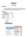
All programs use a special text style called "SSDCP" to enable the computer to print
stacked fractions on the drawing. In order to create this special style, you must assign
two different font file names to the style name. One is a standard font file and the other is
a big font file. When you type a letter on the screen, AutoCAD looks through two different
shape files to find the correct ASCII code to enable the computer to know what letter or
number to print on the screen. This special style shape file will be called SSDCP. It will
contain the "SIMPLEX.SHX" file to take care of all the upper and lower case letters and a
big font file called "SPEC.SHX" which will print the stacked fractions.
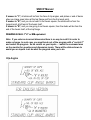
In order to print a stacked fraction when you are in the text mode of AutoCAD, you must
use the following input keys:
input
`1
`2
`3
prints
1/16
1/8
3/16
SSDCP Manual
`7
`8
`9
`0
`q or `Q
`w or `W
`e or `E
`r or `R
`t or `T
7/16
1/2
9/16
5/8
11/16
¾
13/16
7/8
15/16
In order to print special symbols when you are in the text mode of AutoCAD, you must
use the following input keys:
input
prints
`S
Diameter Symbol
`D
Prints "stacked" plate symbol
`F
Prints "stacked" centerline symbol
`J
+/- Symbol
`K
Degree Symbol
`[
Subscript L (for shipping & assembly marks)
`]
Subscript R (for shipping & assembly marks)
`{
Subscript R/L (for shipping & assembly marks)
`(
(N.S.)
`)
(F.S.)
`*
(1-N.S. & 1-F.S.)
`!
(CTR'D)
`%
MK
The ` key is just to the left of the number 1 on the top row. Press the ` once, then any
number or letter as shown above. Do not hold the ‘ key down. To print a stacked fraction
when in the text mode of Autocad:
Example: Type 11'-1`3 to print 11'-1 3/16 in-stacked format.
This is not related to entering dimensions in the programs in any way. Enter dimensions
in your usual manner.
In the "setup.lsp" program there are three lines of code that can be modified by you,
should you wish to change the way the letters, numbers, or fractions look. Use a text
editor to do this. The lines look similar to the following:
(COMMAND "STYLE" "SSDCP" "SIMPLEX,SPEC" 0.0 0.8 0 "N" "N" "N")
Ref. No. 1
2
3
4 5 6 7 8 9
SSDCP Manual
The only numbers you can change are the Ref. No. 5 and 6. All other text or numbers will
remain as shown. If you change one line, make sure you change all three lines the same
way so all text will look alike.
The Ref. no. 5 (0.8) will set the width of the letter in relation to the height.The Ref. no. 6
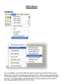
(0) will set how far the letter "leans over" from a vertical position.
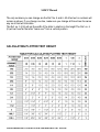
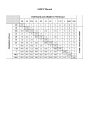
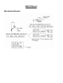
CALCULATING PLOTTED TEXT HEIGHT
CONVERSION CHART FOR INSERTING BLOCKS
SSDCP Manual
SSDCP Manual
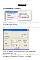
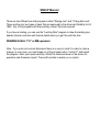
SSDCP Manual
This will start the online help system.
SSDCP Manual
SSDCP Manual
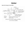
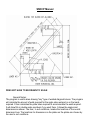
LEVEL BEAMS
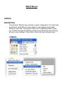
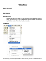
DESCRIPTION
When you first load this program, you will be required to setup the global
questions to suit the way you want beams to be detailed on the current sheet. It
would be wise if you go thru each question, so you will know what they control.
You will have the option to change these between every beam detail. The
answers will be written to the hard drive in a file called "BEAM.GQU." Depending
on how you answer these questions, these will have a direct bearing on what
questions are asked in the program, when it is run. Try to group beams that are
similar, on one sheet. This will eliminate some questions when the program
runs.
COMMAND
OPTIONS
A. END OF BEAM CONNECTIONS
1. Clip angles (both sides, near side or far side) ("safety" connection provided if
req’d at WF cols.)
SSDCP Manual
5. Plain ends
6. Clips can be welded or bolted. Holes in bolted clips will be staggered if req’d
only at WF cols.
7. Gages in clips will be adjusted for channels (optional)
8. Standard or custom clip angle marks (optional)
B. INTERNAL CONNECTIONS
1. Top or bottom flange holes
2. Open holes or 4 different type of shear bars in webs.
3. Stiffeners drawn and sized.
4. Running dimensions from beam to beam can be above or below beam.
5. Stub dimensions to 1st hole only, or every row of holes or bars.
6. Holes drawn in web or bottom flanges for horizontal bracing connections.
(Level only)
C. MISCELLANEOUS CONNECTIONS
1. Wood holes shown and noted in top or bottom flanges.
2. Handrail holes or bars in web of beam. (Level only)
D. DIMENSIONING
1. All dims. can be from end of beam or face of clip angles
2. Calculates all minus dims, block sizes, and stub dims.
If you are dealing with a channel, any references in the program to "C/L" will
logically mean to "BACK" of channel.
DRAWING SCALE: 1"=1' or MM equivalent TO RUN:
Note: If you enter an incorrect dimension there is no way to recall it in order to
make a change. In such case, you must break out of the program with a "control C"
and restart the program. So be careful on your inputs…. watch the command area
on the monitor for questions and dimension inputs. There will be slides shown to
assist you on inputs. Just do what the program asks you to do.
SSDCP Manual
SSDCP Manual
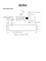
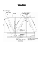
COLUMNS
COMMAND
OPTIONS
1. Up to 3 faces of the column can be drawn. Face "B" must always be drawn. If you
have girt clips on face "A" OR "C" then those faces must be drawn.
2. 2 different ways to tie up overall dimension on column.
3. Will detail WF, S Shape, Tube Steel, Pipe or Special Columns
4. Will print compass direction on face "A" if required.
BOTTOM OF COLUMN OPTIONS
1. Base Plates with 2 or 4 holes
2. Plain
3. Open holes for splice plates
TOP OF COLUMN OPTIONS
NOTE: Cap plates will be drawn in face "B" only.
1. Cap plates with open holes or plain
SSDCP Manual
INTERNAL CONNECTIONS
1. Open holes
2. Brace holes above or below beam for vertical brace connections.
3. Wing plates
4. Moment connection detail & material for bolted moment connections.
5. Different types of girt connection material.
6. Vertical bracing plate details. (vertical bracing plate program)
7. Stiffeners drawn and sized.
When you first load this program, you will be required to set up the global questions to
suit the way you want columns to be detailed on the current sheet. It would be wise if you
go thru each question, so you will know what they control. You will have the chance to
change these between every column detail if you wish. The answers will be written to the
hard drive in a file called "COL.GQU." These will be read back in for the defaults used for
the next day, week, month, year, or century. Depending on how you answer these
questions, these will have a direct bearing on what questions are asked in the program,
when it is run.
SPECIAL NOTE PERTAINING TO PUNCHING HOLES IN WF COLUMNS
The holes punched in face "A" or "C" (flanges) for a WF column can be drawn in those
faces even if you are "only" drawing FACE "B". However, if you choose to draw face A
or C, the flange holes will be drawn in those faces. If you are NOT drawing face "C", the
holes in face "C" will be put in the right side flange in face "B" picture. The dimensions
and stubs will be to the right of face "B" picture. If you are NOT drawing the "A" face the
holes in face "A" will be put in the left side flange of face "B". The dimensions and stubs
will be to the left of face "B". The holes for web punching in face "B" are also to the left
side. This could cause some conflict of dimensions overrunning other dimensions. If the
Beams framing into face "A" and face "B" are at the "same elevation" everything should
be O.K. If the beams are "NOT" at the same elevation, then you should pick 2 different
locations to draw holes for face "A" and face "B".
SSDCP Manual
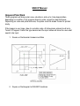
ENTERING ELEVATIONS
Enter "ALL" elevations that will pertain to this drawing. Example: Base Plates, top of
column, beam elevation., etc, etc: These elevations will be printed on the sheet, so that
you may just "PICK" these, when the program requests an elevation. This is much
easier than typing these, over and over again. After you have entered all these elevation
for this sheet, you could make a "Block" of these elevation to insert on next sheet of
columns, so you don't have to enter these again. If you made a block of the elevation
list, if you drew the elevations on this bldg., you can insert this block on this sheet before
you start to run this program. (explode block)
NOTE: While the program is running and you "missed" entering an elevation, pick a
"blank" area on sheet and the program will ask for you to "enter" the elevation. This
elevation will be used and also added to the list, so you don't have to enter it again.
WING PLATE INFORMATION
As you can see by the manual, if you have several different wing plates at the same
elevation, the pictures can overrun each other and make it very confusing. There is no
way the computer can know in advance what the conditions might be. Therefore the
program will let you decide where you want to draw each wing plate so there won't be
overlap of pictures. Even if the elevations are the same, you must draw plates at
different locations on column for clarity.....
MOMENT CONNECTION INFORMATION
The program will only draw a "field welded" moment connection framing into a column
web. if you have a moment connection for the flange of a column, use the wing plate
portion of the program above to draw this fit- up bar.
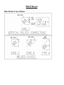
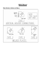
GIRT CONNECTION INFORMATION
Refer to manual to decide on girt connection type number. These are blocks that will be
inserted for you to manually change.
DRAWING SCALE: 1"=1' or MM equivalent
Note: If you enter an incorrect dimension there is no way to recall it in order to
make a change. In such case, you must break out of the program with a "control C"
and restart the program. So be careful on your inputs…. watch the command area
on the monitor for questions and dimension inputs. There will be slides shown to
assist you on inputs. Just do what the program asks you to do.
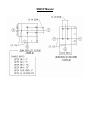
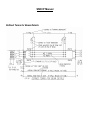
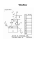
SSDCP Manual
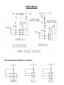
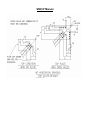
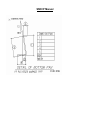
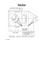
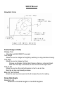
Base Plate Input
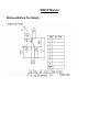
SSDCP Manual
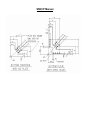
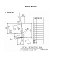
Symmetrical Cap Plate Input
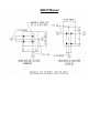
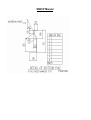
SSDCP Manual
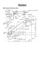
Offset Cap Plates
SSDCP Manual
SSDCP Manual
SSDCP Manual
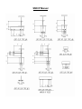
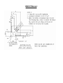
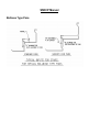
Column Splice Details
SSDCP Manual
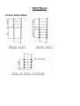
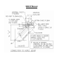
Wing Plate Details
SSDCP Manual
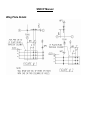
Girt Connection Details to Columns
SSDCP Manual
SSDCP Manual
SSDCP Manual
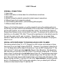
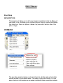
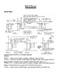
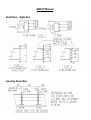
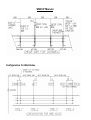
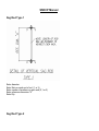
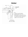
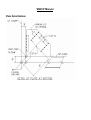
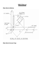
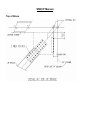
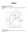
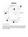
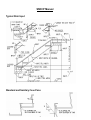
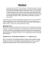
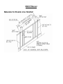
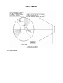
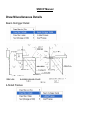
Pour Stop
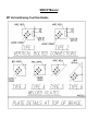
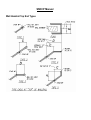
DESCRIPTION
This program will allow you to add a pour stop (screed plate) to the top flange of
your beam or tee. It allows you to construct the pour stop by entering information
in a dialog box. There are options to draw a top view and a section view of the
plate or angle.
COMMAND
The pour stop program has been enhanced to make adding angle or bent plate
screed material to your details easier. The dialog is very user friendly. You just
place checks in the checkboxes (or make choices with button selections) beside
SSDCP Manual
use a new feature to SSDCP that once the program draws your material on the
detail, it will allow you to drag the dimensions where you want them or need them
to miss other dimensions. You are able to see where these dimensions are going
at all times while you are dragging it. See explanation of each below the image.
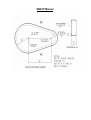
SSDCP Manual
SSDCP Manual
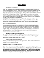
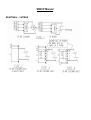
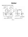
Weld Group
Angle/Bent Plate
The next time you use the lintel program, the
last entered length will be shown. If you want to
use that length, click "Use".
This will apply the weld you specify to your
section. You can use the dropdown list to select
your weld size. You can add a weld pattern if
needed (i.e. 2-12, 2-8)
Radio button to choose either Angle or Bent
Plate. This will determine what types of
dimensions are shown in your section if you
choose that option. Bent plate shown in your
section will have bend dimensions shown.
Offset
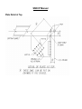
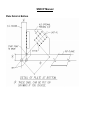
Drawing Instructions
This radio button allows you to choose whether
your plate is offset to the near side or far side. If
your plate is centered, you may choose either
one.
The checkboxes allow you to choose how you
want your plate shown. You can have it draw a
top view, if needed. If you want the angle or
bent plate shown in your existing section, check
the draw section box. There are two checkboxes
that allow you to choose which flange the angle
or bent plate is drawn on. You can choose one
or the other or both. When you check a box, the
textboxes located at the bottom of the slide for
top and bottom will be enabled or disabled
according to your choice.
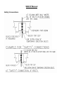
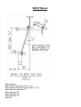
Top or Bottom Plate Entries
Stop distance left
Stop distance right
Vertical Leg
Horizontal Leg
Enter a positive number to hold back from the
end of assembly or a negative number to extend
past the end of the beam.
Enter a positive number to hold back from the
end of assembly or a negative number to extend
past the end of the beam.
Enter the vertical dimension of your angle or
bent plate
Enter the horizontal dimension of your angle or
bent plate
SSDCP Manual
Offset from CL
plate, you may enter it here. This is not a
required number.
This will the distance from beam center line to
the edge of your plate or angle.
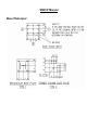
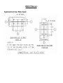
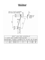
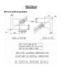
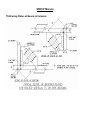
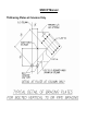
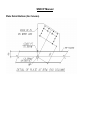
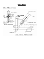
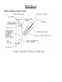
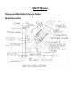
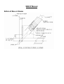
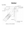
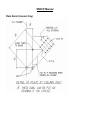
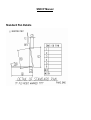
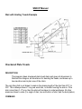
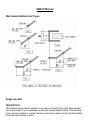
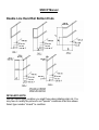
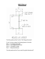
Add Beam Lintel Plates
SSDCP already has a lintel program; this new program adds lintel plates to
structural beams. The dialog is very user friendly. You just place checks in the
checkboxes beside the way your detail should look and enter the required
numbers. Note that this example is showing the numbers entered with CVSpro
input style. Your input will depend upon your setting in SSDCP options. This
program and the pour stop program use a new feature to SSDCP that once the
program draws your material on the detail, it will allow you to drag the
dimensions where you want them or need them to miss other dimensions. You
are able to see where these dimensions are going at all times while you are
dragging it. See explanation of each below the image.
SSDCP Manual
SSDCP Manual
Beam Length
Weld Group
Offset
Drawing Instructions
Stop distance left
Stop distance right
Plate Width
Plate Thickness
Stock Length
Offset from CL
Enter the point-to-point length of your beam. The next
time you use the lintel program, the last entered length
will be shown. If you want to use that length, click
"Use".
This will apply the weld you specify to your section.
You can use the dropdown list to select your weld size.
You can add a weld pattern if needed (i.e. 2-12, 2-8)
This radio button allows you to choose whether your
plate is offset to the near side or far side. If your plate is
centered, you may choose either one.
The checkboxes allow you to choose how you want
your plate shown. You can have it draw a top view, if
needed. If you want the plate shown in your existing
section, check the draw section box. There are two
checkboxes that allow you to choose which flange the
plates are drawn on. You can choose one or the other
or both. When you check a box, the textboxes located
at the bottom of the slide for top and bottom will be
enabled or disabled according to your choice.
Top or Bottom Plate Entries
Enter a positive number to hold back from the end of
assembly or a negative number to extend past the end
of the beam.
Enter a positive number to hold back from the end of
assembly or a negative number to extend past the end
of the beam.
Enter the actual width of your plate.
Enter the thickness of the lintel plate.
If your chop or client uses stock lengths for plate, you
may enter it here. This is not a required number.
This will the distance from beam center line to the edge
of your plate.
SSDCP Manual
ADD BEAM OUTRIGGERS
This routine will draw outrigger details on beams. You have the following options:
1. Either bent plates or angles
2. The brace is optional
3. The horizontal angle is optional.
4. The studs and spacing are optional.
You can use the SSDCP programs to draw the continuous angle or bent late, then copy
the front view to any locations you choose. You will have to dimension the details to suit
yourself. If you use the "green" node point to copy the side view, this will be the top
flange of the beam.
The dimensions C2, D2, G and E can be entered as 0" if required.
SSDCP Manual
The dimensions C2, D2, G and E can be entered as 0" if required.
SSDCP Manual
COLUMN WEB SAFETY ANGLES
With the new OSHA requirements, detailers may opt to use angles in the column web
to achieve the safety connection.
After you issue the command, you can set your needed information in this dialog box:
1. Pick your beam size (uses the standard SSDCP shape selection dialog)
2. Set your shim space, if any.
3. Choose your angle size, the length of the angle and the cc distance in your web.
4. Set whether the angle occurs on the NS or FS of column web.
SSDCP Manual
After your make all your selections in the dialog box, you will be asked to select the top
of steel at the column centerline. After the angle and dimension lines are drawn, the
program will ask you for the stub dimension to the top of steel and the program will
calculate the stub dimension to the bolted connection. If it is a welded connection, after
you pick the top of steel, it will draw the angle and add a 3-sided weld to the detail.
Example of Safety Angle
SSDCP Manual
COLUMN WEB STIFFENER PLATES
A moment connection often means column web stiffeners. After you choose the
command to add these stiffeners the dialog box will allow you to add the needed
information so SSCP can draw them in your existing column.
This dialog box allows you set exactly how you wish to have the column stiffeners
appear. Select the sides that the beams frame in, and choose the beam size. Note that
the routine will draw the bottom stiffener at an angle if the beams are different depths.
You can select if the routine does not draw top or bottom plates, it does draw them by
default. You also need to enter your stub dimension so the routine can calculate the
stub dimension.
SSDCP Manual
Example of Column Web Stiffener
Column End Prep
This command will draw prepared ends on your column.
SSDCP Manual
SSDCP Manual
ERECTION PLANS
COMMAND
DESCRIPTION
The best way to use this program is to draw the anchor bolt plan first. After you are
through with the anchor bolt plan, save this sheet with a new drawing name (Ex. 300E1). Then bring up this drawing (300- E1) and tell the program that you are using an
existing anchor bolt plan. At this time, the program will turn off the CLA layer which is the
C/L of columns and the type numbers. These items will no longer be required. The
program will only ask where the columns are and the sizes of beams or joists to be added
for erection purposes.
The program will draw the beams and/or joists anywhere you want to scale. However,
because the program will not know in advance the conditions that could develop as you
add beams or joists, it will not dimension these beams or joists as they are drawn.
When the program is complete, use the standard AutoCAD dimension commands to
dimension the beams to suit the situation and locate the dimension lines in clear areas
that you have on the sheet. Because the beams are located to scale, you can accept all
dimensions that are provided by this method.
As this program develops the drawing, you will note green X's (node points) drawn at C/L
of columns and beams. You can use these points to dimension to or from. Just set your
SSDCP Manual
As with any program, you need to use the array or copy standard AutoCAD commands
when possible. This saves time if other bays have the same conditions as the one you
just drew. Think about this, and do a little planning before you start drawing.
If you have an entire building that is on any angle other than 0 and 90 degrees, draw the
plan square on sheet. After the plan is complete, use AutoCAD command "rotate
window", and rotate entire plan to any angle you choose.
If you are going to draw a metal decking layout sheet, you should save the erection
drawing under another name to be used to draw the layout sheet for the decking. As this
drawing is drawn to scale, it is very simple to layout the decking sheets on this drawing.
OPTIONS:
1.
2.
3.
4.
Will draw and put bubbles on all column grid lines.
Will draw beams or joists on C/L of columns.
Will draw beams or joists in any interior bays.
The anchor bolt plan will indicate anchor bolts in plan that are not
symmetrical for all TS or pipe columns so that the contractor will not set
anchor bolts in the wrong direction.
5. Will let you select column and beam sizes from sidebar menu.
6. You may add any note to beams in plan (Ex (+2 ½ )).
7. Will ask about column "type numbers" and orientation.
NOTE: The "type numbers" refer to the type of anchor bolt setting that you will draw using
the Anchor Bolt Settings" program. You will have to draw these on another sheet at a
1"=1' scale. If you want, you can make blocks from these details and insert them on the
anchor bolt plan. Use the "conversion chart for inserting blocks" in the manual for the X
and Y scale values. See manual for anchor bolt setting documentation.
8. Use the icons for erection for inserting two different types of north- south
arrows for direction.
9. The size of the column pictures will be larger than normal to show correctly at
the smaller scale.
10. You may select any direction to draw wide flange and non- rectangular tube
steel columns.
11. The program will not draw a beam or a joist on an angle. You will have to do
this manually after the program is complete.
12. Will draw lines of "bridging" in bays that contain joists.
SSDCP Manual
DRAWING SCALE: 1/8" OR 1/4" = 1' or MM equivalent
Note: If you enter an incorrect dimension there is no way to recall it in order to make a
change. In such case, you must break out of the program with a "control C" and restart
the program. Enter your inputs carefully. Watch the command area on the screen for
questions and dimension inputs. There will be slides to assist you on inputs.
ANCHOR BOLT SETTINGS
DESCRIPTION
This program draws anchor bolt setting details for wide flange, tube or pipe
columns. The program will draw 2 or 4 hole plates, rectangular or square or
offset plates. It will not draw a setting with only 3 holes, but you can manually fix
the detail to accommodate this condition very easily.
COMMAND
You can easily detail anchor bolt settings now with this user-friendly dialog. By
entering your dimensions in the textboxes and selecting options, such as leveling
plate or leveling nuts, all your needed information can be used (and retained) to
SSDCP Manual
SSDCP Manual
SSDCP Manual
Column Selection
This textbox will show the column that is currently selected. If
you need to change the size or type of column, click on "New
Shape". The standard SSDCP Shape selection dialog box will
allow you to choose the shape.
Base Plate
Elevation
This group of textboxes is where you will enter finished floor
elevations, dimension to top of concrete, base plate and grout
thickness. SSDCP will calculate the bottom of base plate
dimension based on these entered dimensions.
This group of textboxes is where you define your anchor bolts
dimensions. The program will give you the opportunity to detail
your anchor bolt after it draws the setting. It will use these
dimensions for the detailing of the anchor bolt.
You can choose to use a leveling nut or a leveling plate. If you
choose the setting (leveling) plate option the textbox for the plate
thickness will be enabled so you can enter the size in.
Enter the amount of projection above the concrete. This is an
over-ride if you want to add projection to the amount calculated
by SSDCP.
Anchor Bolt
Dimensions
Options
Bolt Projection
DRAWING SCALE: 1"=1' or MM equivalent
NOTE: If you want to add these details to an anchor bolt “plan” which is drawn to (ex. 1/4 to 12)
scale, you will have to draw these on another sheet at a 1" to 1' scale and then make a block out
these details to insert them on the Anchor bolt plan at the correct conversion number for inserting
blocks. (See conversion chart for inserting blocks.)
Anchor Bolt types
There are four anchor bolt types that you can detail. Types 1 and 2 are hooked and types
3 and 4 are straight rods.
Type 1 – 1 nut and washer
Type 2 – 2 nuts and washers
Type 3 – 1 nut and washer
Type 4 - 2 nuts and washers
SSDCP Manual
SSDCP Manual
X-Bridging for Joists
Draws x-bridging on erection plans by picking joists
Misc. Grid Bubbles
SSDCP Manual
Cut Sections
1.
2.
3.
4.
5.
6.
Pick direction of section (Left, Right, Down, Up)
Enter letter for section (i.e. A, B, C …..)
Enter erection sheet number (i.e. E1, E2, …)
Pick location for arrow
Pick the start point for section line
Drag the line in the direction the line is to be placed and length of line
Draw Block Wall Sections
Select SSDCPà Other Main Programs à For Erection à Draw BLOCK WALL
sections
SSDCP Manual
1. Wall Type
SSDCP Manual
If block is selected:
Enter block width
Enter block height
Enter mortar thickness
Enter number of courses to be shown
If a bond beam is at the top of the wall, make sure this is checked.
If the user wants to pick where to start the bottom of the wall, make sure this is
checked.
If concrete is selected:
Enter wall width
Enter wall height
Mortar thickness and number of courses are disabled
Bond beam selection is disabled
If the user wants to pick where to start the bottom of the wall, make sure this is
checked.
SSDCP Manual
selected as the anchorage method. If no bearing plate is selected, anchor bolts
may be used.
You can set the width, length and thickness of a bearing plate. The alignment of
the plate can be centered on the wall or placed to the left or right edge of the
wall. The example above uses anchor bolts as the anchorage method. Set
diameter, projection (from top of wall), length (embedment), gage (can be “0”),
hook, and amount of grout (if any).
SSDCP Manual
3. Block Wall Hatch
Select any type hatch to be applied on the wall
CMU Hatch
Concrete
Hatch
Brick Hatch
No Hatch
SSDCP Manual
4. Block Wall Input Options
Selection 1 – elevation at the top of the wall
Selection 2 - Enter top of steel elevation and then either
a) enter dimension down to top of wall
or
b) select shape and the program will calculate the vertical offset
5. Block Wall Vertical Line
Draws a vertical work line to the left or right of the wall. Enter amount of offset
from face of wall.
SSDCP Manual
DRAW BRICK WALL SECTIONS
Select SSDCPà Other Main Programs à For Erection à Draw BRICK WALL
sections
For an explanation of each area, see the corresponding number in the graphic
with notes below.
SSDCP Manual
SSDCP Manual
1. Insertion Point
Select either right or left as the insertion point (face of brick)
2. Work Line Elevation
Enter the elevation of the work line. Check “Show on Drawing” to have elevation
text shown on work line.
3. Brick Size
Enter brick width, height and mortar dimension thickness.
SSDCP Manual
4. Top of Brick Elevation
Elevation at top of brick – will draw to scale elevation entered minus work
elevation entered
Dist A – will draw to scale the distance entered
Pick – allows user to pick point to draw to
Auto-Dim – will dimension distance from work line to top of brick
Show Elev – will show elevation text at top of brick
5. Bottom of Brick Elevation
Elevation at bottom of brick – will draw to scale elevation entered minus work
elevation entered
Dist B – will draw to scale the distance entered
Pick – allows user to pick point to draw to
Auto-Dim – will dimension distance from work line to bottom of brick
Show Elev – will show elevation text at bottom of brick
SSDCP Manual
6. Brick Course
Select “top” or “bottom” to set where brick course is drawn from
7. Brick Hatch
No Hatch
CMU Hatch
Brick Hatch
Concrete Hatch
SSDCP Manual
Sloping Beam
DESCRIPTION
This program will draw sloping beams in "position" to scale. There will be two
work points at each end of beam. The main wp will be at the center of the
support point, and the 2nd wp will be the face of clips, end plate, or end of beam
when you have open holes. Elevations printed on drawing will be to the 2nd work
point. All overall dimensions will be from 2nd wp to 2nd wp. Blocks will be
dimensioned. All stubs to holes will be dimensioned from point as selected by
line "0" in global questions.
COMMAND
THE FOLLOWING RULES WILL APPLY FOR SLOPED BEAMS:
1. The ends of all beams will be cut on a bevel. If you want the beam to be cut square,
you will have to modify the picture and adjust the "cut length" after the program has been
completed.
2. All open holes, clip angles, and end plates at the ends of the beams will be drawn
vertical. If condition exists "rotate" clip angles or end plates to suit after program is
complete.
3. All interior beam connection holes or shear bars will be drawn perpendicular to top
flange.
4. All beam to beam framing is assumed to be flush top.
SSDCP Manual
If answer is "C", all stubs will be from the face of clip angles, end plates or end of beam
when you have open holes at the top flange and from the 2nd work point.
If answer is "B", and you do not want to cut beam square, the stubs will be from the
longest point at left end of the beam itself.
If answer is "B", and you are going to cut beam square, then the stubs will be from the
end of the beam itself, at the top flange.
DRAWING SCALE: 1"=1' or MM equivalent
Note: If you enter an incorrect dimension there is no way to recall it in order to
make a change. In such case, you must break out of the program with a "control C"
and restart the program. So be careful on your inputs…. watch the command area
on the monitor for questions and dimension inputs. There will be slides shown to
assist you on inputs. Just do what the program asks you to do.
Clip Angles
SSDCP Manual
Defined Terms for Beam Details
SSDCP Manual
Beam Cuts Framing to Column Webs
SSDCP Manual
Special Block Input
SSDCP Manual
Left End Beam Connections
SSDCP Manual
Right End Beam Connections
SSDCP Manual
Shear Bars
SHEAR BARS FOR WF or CHANNEL BEAMS
NOTES:
TYPE 1 – Holes can be inside or outside of flanges, plate not fitted.
TYPE 2 – Holes are normally inside flanges, but edge of plate must extend a little bit
beyond flanges. Clipped corners cheaper to fabricator than types 3 or 4.
TYPES 3 or 4 – Holes can be inside or outside of flanges, plate must extend beyond
flanges. Notched plate more expensive to fabricator than type 2.
TYPE 5 – Holes must be inside flange, uses standard stiffener bar width only.
SSDCP Manual
End Plates – Left End
SSDCP Manual
End Plates - Right End
Inputting Shear Bars
SSDCP Manual
Configuration for Web Holes
SSDCP Manual
Pipe Handrail Connection to Beam
SSDCP Manual
Angle Handrail Connection to Beam
SSDCP Manual
Safety Connections
SSDCP Manual
Skewed Beams
COMMAND
DESCRIPTION:
This program will draw a skewed connection for a horizontal beam in any
direction and on any bevel. This program will draw a top view of the flange and
the elevation of the beam or channel and will draw one of three different type
connections: Bent plates, End plates, or Open holes. This program will give all
dimensions for block sizes and all other dimensions to bend lines, etc. required
for the shop. However, it only draws the ends of the beams one at a time.
These can be easily assembled together to complete the beam detail to suit,
using standard AutoCAD commands. Modify the picture and add overall
dimensions as required to suit.
You have to consider nut clearance before entering the "D2" dim. for TYPE 1 and 2, and
"D1" for TYPE 3 (See manual). If you do not the "D2" dim. for TYPE 1 and 2, OR "D1"
dim. for TYPE 3, enter a small dimension, such as one inch. The program will calculate
the minimum "D2" dim. or "D1" dim. This will ensure that the nut can be put on the bolt.
Because the program draws to scale, some dimension lines may be very close together.
When plotted, these lines may become one line depending on pen size. This makes it
difficult for the shop to tell where the lines go to. After the program is complete, you may
SSDCP Manual
DRAWING SCALE: 1"=1' or MM equivalent
Note: If you enter an incorrect dimension there is no way to recall it in order to
make a change. In such case, you must break out of the program with a "control C"
and restart the program. So be careful on your inputs…. watch the command area
on the monitor for questions and dimension inputs. There will be slides shown to
assist you on inputs. Just do what the program asks you to do.
Skewed Beam End Connections
SSDCP Manual
SSDCP Manual
SSDCP Manual
SSDCP Manual
Adding Skewed Plates to Beams
COMMAND
DESCRIPTION
This program is for adding a skewed plate in any direction, and on any bevel to a beam
detail. This program will draw a view of the plate above the beam and project the plate
down into the beam web. However, you can use this program to draw other type skewed
plates, but you might have to mirror, rotate, or move the details to suit other conditions
after the program is complete.
There are two (2) things you have to consider before entering the "D1" dimension.
1. Beam clearance
2. Nut clearance
If you don't know the "D1" dimension, enter a small dimension. The program will
calculate the minimum "D1" dimension. this will insure the nut can be put on the bolt.
You will have to check to make sure the beam can be bolted to the plate. This could
change the "D1" dimension from that calculated.
DRAWING SCALE: 1"=1' or MM equivalent
Note: If you enter an incorrect dimension there is no way to recall it in order to
make a change. In such case, you must break out of the program with a "control C"
SSDCP Manual
SSDCP Manual
SSDCP Manual
GIRTS
DESCRIPTION
This program draws channel girts for siding on buildings. The program will handle
connections to corner or interior columns, and to doorframes. The program will locate and
draw sag rod holes and open hole connections for door frames. For this program to
work correctly, you must detail girts looking at girts from outside of the building.
COMMAND
CONNECTION INFORMATION
NOTE: The first time through the program you will be required to give dimensions to all
questions asked. After that, the program will ask if this end you are drawing is exactly like
the last end that you drew. This not only applies to the type of end, but also to the left and
right ends. Because hole spacing for end connections will probably be the same for all
girts on a job, this is an easy way of locating the holes in the ends of the girts. You can
also add special block input for copes.
You will be shown slides for the condition you have:
Corner Columns
Interior Columns
Door Jambs
EXAMPLE: You are detailing a girt that frames to interior columns at both ends. Once
you have given the dimensions for the left end, the program will ask if the right end is the
SSDCP Manual
IF YOU WANT TO DRAW THE DOOR FRAME DETAILS:
The program will insert the door frame block. Pick a large clear area on the sheet. See
the manual for location of insertion point. There are two different types of door frames in
the block. Pick insertion point.
Will insert the DRFRM.DWG on the sheet. You may then move this block where you want
to, explode the block and change it to suit.
DRAWING SCALE: 1"=1' or MM equivalent
Note: If you enter an incorrect dimension there is no way to recall it in order to
make a change. In such case, you must break out of the program with a "control C"
and restart the program. So be careful on your inputs…. watch the command area
on the monitor for questions and dimension inputs. There will be slides shown to
assist you on inputs. Just do what the program asks you to do.
Girt Connections at Columns
Screenshots below show questions that will be asked when you are detailing the girts.
SSDCP remembers the last input condition to speed the detail process along, so use
your own detailing experience to decide the order you detail the girts in. (i.e. – detail all
corners conditions together, then interior conditions together)
SSDCP Manual
SSDCP Manual
Door Jambs
Door jamb details can be done by answering questions from the slides below. After
detailing these, you can place a generic drawing (after being prompted by the system) of
a door frame and fill in the blanks.
SSDCP Manual
Generic Door Details
SSDCP Manual
SSDCP Manual
Sag Rods
DESCRIPTION
This program will draw either straight or bent SAG RODS. This information is put
into a TABLE format UNDER the picture. Before you run this program, make a
list of the sag rods including the QUANITY and the VERTICAL DISTANCE (REF.
DIMS.) between the GIRTS. The length of the rods will be rounded up or down to
the nearest even inch (IF ENGLISH).
The shipping mark system used for these sag rods is:
1. For straight rods: "X" + length of rod in inches (mm).
2. For bent rods: "XX" + length of rod in inches (mm).
COMMAND
SSDCP Manual
Sag Rod Type 1
Enter diameter
Enter Nuts on each end of rod (1 or 2)
Enter number of washers on each end (0,1 or 2)
Enter reference dimension "A"
Enter Qty.
Sag Rod Type 2
SSDCP Manual
Enter diameter
Enter Nuts on each end of rod (1 or 2)
Enter number of washers on each end (0,1 or 2)
Enter reference dimension "A"
Enter dimension "B"
Enter dimension "C"
Enter dimension "D"
Enter Qty.
SSDCP Manual
SSDCP Manual
SSDCP Manual
LINTELS
DESCRIPTION
This will draw 7 different types of lintels in various configurations. The lintel types
are shown in a slide after your have entered in your masonry opening and
bearing for each end. The program makes use of a standard window to allow
you to choose the type of material you will be using. Remember when choosing
an area on your drawing for these lintels, that an end view is always shown.
COMMAND
SSDCP Manual
Lintel Types
SSDCP Manual
SSDCP Manual
Example of finished lintel
SSDCP Manual
Add Notch or Block
To add a cope (block)
Note that you must already have at least two lines drawn forming a corner before this
routine can be run.
1.
2.
3.
4.
5.
6.
7.
8.
9.
Pick approximate location of cope
Enter cope length (for text label)
Enter cope depth (for text label)
Inside radius of cope (0= square corner)
Pick the intersecting corner
Drag line for cope length
Drag line for cope depth
Pick point to locate the text label for the cope
Cope is drawn, trimming all needed lines.
SSDCP Manual
WT Bracing
DESCRIPTION
This program draws WT horizontal bracing. This program writes files in your
AutoCAD directory to be used when you start to draw the bracing plates on the
beams if they are not bolted to the brace. The program will use the shipping mark
and a .HOR extension for the file name. An example of this would be 3D1.HOR.
If the brace starts and stops at the cross point, the file will use the first shipping
mark for the file name, even if there are two shipping marks.
COMMAND
Use caution if you have two different jobs you are working on and the brace shipping
marks could be the same. If the shipping marks are the same, this could cause the files
for the second job to overwrite the files for the first job. After you have finished the job
and you no longer need the brace files, you can erase all files that have a .HOR
extension name from your AutoCAD directory.
WT Brace, connections and bevel are drawn to scale. The length from W.P. TO W.P is
not drawn to scale. You will have an option to let computer determine how big to draw
picture or you may decide.
OPTIONS
1. Any size WT brace bolted through flange.
2. X bracing cross point can be open hole, bolted plate, or brace. Will stop and start.
3. Will calculate holes in brace if brace bolts to bottom of interior beams.
SSDCP Manual
6. Loads can be entered or the program will calculate loads based on the brace size for
the number for bolts required in the brace and vertical & horizontal connections in the
plates. When the loads are given, the program uses 50% of the effective strength for
comparison. SSDCP, Inc. does not assume any responsibility for this design.
7. The program will only draw bracing from lower left to upper right. You may mirror the
picture afterwards if you wish.
DRAWING SCALE: 1"=1' or MM equivalent
Note: If you enter an incorrect dimension there is no way to recall it in order to make a
change. In such case, you must break out of the program with a "control C" and restart
the program. Enter your inputs carefully. Watch the command area on the screen for
questions and dimension inputs.
SSDCP Manual
WT Brace Top Plate Details
SSDCP Manual
SSDCP Manual
SSDCP Manual
WT Brace Bottom Plate Details
SSDCP Manual
SSDCP Manual
SSDCP Manual
WT Brace Connections to Interior Beams
SSDCP Manual
SSDCP Manual
Angle and WT Bracing
DESCRIPTION
This program is for either type of vertical bracing. This program will write files in
your AutoCAD directory to be used when you start to draw the bracing plates on
the beams or columns. The program will use the shipping mark and a .HOR
extension for the file name. An example of this would be 3D1.HOR. If the brace
starts and stops at the cross point, the file will use the first shipping mark for the
file name, even if you have two shipping marks. Use caution if you have two
different jobs you are working on and the brace shipping marks could be the
same. If the shipping marks do happen to be the same, this could cause the files
for 2nd job to overwrite the files for the 1st job. After you have finished the job and
no longer need the brace files, you can erase all files that have a .HOR extension
SSDCP Manual
COMMAND
OPTIONS:
1. Any size angle or wt brace bolted thru stem with single gage line.
2. Either 1 or 2 angles back to back.
3. Will draw & space fills if required (bar or ring fills).
4. Intersection point of X bracing can be: open hole, bolted plate or the bracing will stop
and start.
5. Will write files for detailing plates on beams or columns.
6. Several different configurations of plates are available.
7. Loads can be entered or program will calculate loads based on brace size for number
of bolts required in brace and vertical. Connections in ls, if bolted to column. When the
loads are given, the program uses 50% of the effective strength for comparison.
SSDCP does not assume any responsibility for this design.
8. The program will only draw bracing from lower left to upper right. You may mirror the
picture afterwards if you wish.
DRAWING SCALE: 1"=1' or MM equivalent
Note: If you enter an incorrect dimension there is no way to recall it in order to make a
change. In such case, you must break out of the program by pressing Ctrl-C on your
keyboard. Restart the program. Enter your inputs carefully.
Watch the command area on the screen for questions and dimension inputs. There will
be slides to assist you on inputs.
SSDCP Manual
Angle Vertical Bracing Top Plate Details
SSDCP Manual
Angle Vertical Bracing Bottom Plate Details
SSDCP Manual
WT Vertical Bracing Details
SSDCP Manual
WT BRACING
Bracing for WT's
DESCRIPTION
This program draws WT vertical bracing. This program writes files in your
AutoCAD directory to be used when you start to draw the bracing plates on the
beams or columns.
COMMAND
SSDCP Manual
The program will use the shipping mark and .HOR extension for the file name. An
example of this would be 3D1.HOR. If the brace starts and stops at the cross point, the
file will use the first shipping mark for the file name, even if there are two shipping marks.
Use caution if you have two different jobs you are working on and the brace shipping
nd
marks could be the same. This could cause the files for the 2 job to overwrite the files
for the first job if the shipping marks do happen to be the same. After you have finished
the job and no longer need the brace files, you can erase all files that have a .HOR
extension name from your AutoCAD directory.
WT Brace, connections and bevel are drawn to scale. The length from W.P. TO W.P is
not drawn to scale. You will have an option to let the computer determine how big to draw
picture or you may decide.
Options
1. Any size WT brace bolted through flange.
2. X bracing cross point can be open holes, bolted plate, or brace. Will stop and start.
3. Will write files to draw connection plates on beams or columns.
4. Several different configurations of plates are available.
5. Loads can be entered or the program will calculate loads. The program will base loads
on brace size for the number of bolts required in the brace and vertical & horizontal
connections in plates. When the loads are given, the program uses 50% of the effective
strength for comparison. SSDCP, Inc. does not assume any responsibility for this design.
6. The program will only draw bracing from the lower left to the upper right. You may
mirror the picture afterwards if you wish.
DRAWING SCALE: 1"=1' or MM equivalent
Note: If you enter an incorrect dimension there is no way to recall it in order to make a
change. In such case, you must break out of the program with a "control C" and restart
the program. Enter your inputs carefully. Watch the command area on the screen for
questions and dimension inputs.
SSDCP Manual
WT Vertical Bracing Top Plate Details
SSDCP Manual
WT Vertical Bracing Bottom Plate Details
SSDCP Manual
Angle, Pipe or WT Knee Brace
SSDCP Manual
TS/PIPE BRACING
Tube Steel and Pipe Bracing
DESCRIPTION
This program draws tube steel vertical bracing or pipe vertical bracing. This program will
only put one fit-up hole in the brace. The amount of field weld will be calculated by the
load or strength of member entered. It will also calculate the length of slot required in
brace to fit over the bracing plate.
COMMAND
This program will write files in your AutoCAD directory to be used when you start to draw
the bracing plates on the beams and/or columns. The program will use the shipping mark
and a .VER extension for the file name. An example of this would be 3D1.VER.
SSDCP Manual
nd
st
cause the files for the 2 job to overwrite the files for the 1 job. The chances of this
occurring are low, but it could happen. After you have finished the job and no longer
need the brace files, you can erase all files that have a .VER extension name from your
AutoCAD directory.
DRAWING SCALE: 1"=1' or MM equivalent
Note: If you enter an incorrect dimension there is no way to recall it in order to make a
change. In such case, you must break out of the program with a "control C" and restart
the program. Enter your inputs carefully. Watch the command area on the screen for
questions and dimension inputs.
Bracing Plates For TS and Pipe
DESCRIPTION
This program draws bracing plates for TS/PIPE vertical bracing. All information to draw plates
will be read from a file created when you detailed the brace. This eliminates a lot of questions in
the program and these files can be given to another detailer for his use when detailing beams.
Normally, you will use this program right after you have detailed the beam or column that this
brace bolts to. Make sure you allow enough room to draw this plate. You may have to move some
things out of the way before running this program.
COMMAND
SSDCP Manual
Note: Do not get confused with Standard Vertical Bracing Pl. program
SUGGESTION
"ZOOM A WINDOW" on the beam or column you are going to add this plate to before running thi
program. If you don't get the plate in the right place to start with, you can use the "MOVE"
command to position it exactly after the plate has been drawn.
OPTIONS
1. Tie up hole to brace work point
2. Only requires you to know the shipping mark for the brace
3. Will calculate stub dimensions to the hole in the place from the left end of the beam or the
bottom of the column.
4. You will have the choice to draw the plate in only two different quadrants, depending
on the bevel of the brace and which end this brace plate is for (top or bottom of brace).
DRAWING SCALE: 1"=1' or MM equivalent
Note: If you enter an incorrect dimension there is no way to recall it in order to make a
change. In such case, you must break out of the program with a "control C" and restart
the program. Enter your inputs carefully. Watch the command area on the screen for
questions and dimension inputs.
SSDCP Manual
Field Welded
TS Vertical Brace Details
SSDCP Manual
SSDCP Manual
SSDCP Manual
TS Bracing Top Plate Details
SSDCP Manual
TS Bracing Bottom Plate Details
SSDCP Manual
Field Bolted
Global Questions
SSDCP Manual
Bottom Brace Details at Beams
SSDCP Manual
Bottom Brace Details at Columns
SSDCP Manual
Top Brace Detail
SSDCP Manual
TS Bracing Plates at Beams & Columns
SSDCP Manual
TS Bracing Plates at Columns Only
SSDCP Manual
Plate Details at Top of Brace
SSDCP Manual
Plate Details at Bottom of Brace
SSDCP Manual
WF BRACING
Flange and Web Bolted
Global Questions
SSDCP Manual
Bottom of Brace (Beams and Columns)
SSDCP Manual
Bottom of Brace at Column Only
SSDCP Manual
Top of Brace Detail
SSDCP Manual
SSDCP Manual
SSDCP Manual
Plate Detail Bottom
SSDCP Manual
Plate Detail Bottom (No Column)
SSDCP Manual
Plate Detail Top (at Column)
SSDCP Manual
Plate Detail (Column Only)
SSDCP Manual
Web Only Bolted
Global Questions
SSDCP Manual
Bottom of Brace at Beams
SSDCP Manual
Bottom of Brace (Column Only)
SSDCP Manual
Top of Brace
SSDCP Manual
Plate Detail at Top
SSDCP Manual
Plate Detail at Bottom
Plate Detail (Column Only)
SSDCP Manual
SSDCP Manual
Flange and Web Bolted (Flange Plates)
Global Questions
SSDCP Manual
Bottom of Brace at Beams
SSDCP Manual
Bottom of Brace (Column Only)
SSDCP Manual
Top of Brace
SSDCP Manual
Plate Detail at Top
SSDCP Manual
Plate Detail at Bottom
SSDCP Manual
Plate Detail (Column Only)
SSDCP Manual
Web Only Bolted (Plates)
Global Questions
SSDCP Manual
Bottom of Brace at Beams
SSDCP Manual
Bottom of Brace (Column Only)
SSDCP Manual
Top of Brace
SSDCP Manual
Plate Detail at Top
SSDCP Manual
Plate Detail at Bottom
SSDCP Manual
Plate Detail (Column Only)
SSDCP Manual
Horizontal Brace Struts
Angles Struts
Routine to detail angle struts and can be single angle or double angle.
Midpoint connection is optional.
SSDCP Manual
SSDCP Manual
WT Struts
Routine to detail WT struts. Midpoint connection is optional.
SSDCP Manual
SSDCP Manual
Miscellaneous Bracing Programs
Quick Check
A routine to allow for quick checking of bracing angles by inputting values as needed by
the dialog.
Odd Bracing Angle
A routine to aid in calculating odd bracing angles. Dimensions are calculated by placing
work points to scale.
SSDCP Manual
Generic Brace Plates
This program will draw "GENERIC" bracing plates. This program DOES
NOT read any files for input. The user will have to input ALL dimensions
and bevels when asked by the program. This is draw bracing plates for
single or double gages.
SSDCP Manual
SSDCP Manual
Pan Stairs
DESCRIPTION
This program draws pan stairs. It gives all dimensions to fabricate the stringers,
all dims for bending the pans, and draws a plan and elevation of the stairs. It will
draw handrail holes in the top flange of channels if required.
COMMAND
SSDCP Manual
There are two different pan stair programs called "Sloping riser" and "30 deg bull nose".
These are the only two types of pans that are approved by the American Disability Act of
1990. Any of the programs will draw sanitary coves if they are required.
If you have a landing, you can use the "Landing Dets" program to draw the landing pan,
header channel, and rear wall channel details when you get thru with the stair.
DRAWING SCALE: 1"=1' or MM equivalent
Note: If you enter an incorrect dimension there is no way to recall it in order to make a
change. In such case, you must break out of the program with a "control C" and restart
the program. Enter your inputs carefully. Watch the command area on the screen for
questions and dimension inputs. There will be slides to assist you on inputs.
SSDCP Manual
Typical Stair Input
Standard and Sanitary Cove Pans
SSDCP Manual
Standard Pan Details
SSDCP Manual
SSDCP Manual
Bottom Pan Details
SSDCP Manual
SSDCP Manual
SSDCP Manual
Stair Inputs for Bullnose Pans
SSDCP Manual
Bullnose Type Pans
SSDCP Manual
Standard Bullnose Pans
SSDCP Manual
SSDCP Manual
Bullnose Bottom Pan Details
SSDCP Manual
SSDCP Manual
Grating Treads Bolted
Grating Treads Welded
DESCRIPTION
This program draws & dimensions bolted grating tread stairs. It will give a stub
dim table to every 7/16" holes for the treads. This program will draw either
standard stairs or ship's ladders and will draw handrail holes in top flange, if
required.
SSDCP Manual
COMMAND
It is not possible to cover all the different ways the stairs are connected at the top and
bottom ends. The most common ways have been chosen. After you get acquainted with
running the programs, you will find there are ways you can "fool" the program to get what
you want. If a stringer needs to be blocked out for framing purposes you may use the
misc. program called "add notch or block" for this.
SSDCP Manual
insertion point is the first 7/16 hole in the tread. If the fabricator wants to ship the
two stringers bolted together using the treads, you will have to add a note telling
the shop the dimension back to back of the stringers. A plan view is not required,
as these stringers will not fit together more than one way with the treads bolted
in. This is an opportunity that you could use the above mentioned blocks to make
your stringers look bolted together. After program is complete, use the icon menu
to select and insert these. There is also a block on a full tread if you need to
show a detail.
You have the option to draw the sloping length to scale if you wish. If you do not want to
draw the sloping length to scale, the stair will be drawn 6" long, real world dimension
unless the slope is less than 6'. Then the stair will be drawn to scale. All other areas are
drawn to scale (i.e. angle of stair and top and bottom of stair).
IMPORTANT NOTE:
The stub dims are going to be figured to the absolute end of the sloping stringer (starting
at bottom). You need to be careful when you enter the figure numbers and the dims when
the bottom of the stair is not doglegged. This will affect the stub dims for the tread holes.
You must enter the horizontal and vertical dims so the absolute end of the channel will be
at the place where the stub dims will be true. You can modify the picture after the stringer
has been drawn.
DRAWING SCALE: STAIRS MUST BE DRAWN AT 1"=1' or MM equivalent
Note: If you enter an incorrect dimension there is no way to recall it in order to make a
change. In such case, you must break out of the program with a "control C" and restart
the program. Enter your inputs carefully. Watch the command area on the screen for
questions and dimension inputs. There will be slides to assist you on inputs.
SSDCP Manual
Stair with Grating Treads Example
Checkered Plate Treads
DESCRIPTION:
This program draws checkered plate tread stairs and gives all dimensions to
fabricate the stringers, all dimensions for bending the treads, and draws up to
two elevations and a plan view of the stairs.
The only thing that is not drawn to scale is the sloping length of the stair from W.P. to
W.P. This is always drawn 6" long real world dim, no matter how big the stair is. If the
stair is less than 6'- 0" long, then the stair will be drawn to scale lengthwise. All other
areas are drawn to scale (i.e. angle of stair, top and bottom of stair, and the bent plates).
COMMAND
SSDCP Manual
OPTIONS
1. Two different types of bent checkered plate treads with open or closed riser material.
2. Two different ends at bottom of stairs
3. Doglegs can be drawn at top or bottom or at both ends of stairs.
4. Each stringer can have different connections at ends.
5. Choice of support angle for landing pans if required.
6. Draw holes in top flange for handrail posts if required.
7. Draw closure bars at end of stringers if required.
8. Will handle "ship's ladders" if required.
DRAWING SCALE: 1"=1' or MM equivalent
Note: If you enter an incorrect dimension there is no way to recall it in order to make a
change. In such case, you must break out of the program with a "control C" and restart
SSDCP Manual
Typical Stair Detail
SSDCP Manual
Standard Tread Details
SSDCP Manual
Tread Type 1
SSDCP Manual
Tread Type 2
SSDCP Manual
Connections at Stairs
Stair Bracing
Draws bracing for stair stringers.
SSDCP Manual
SSDCP Manual
SSDCP Manual
Stair Handrail
Wall Handrail
DESCRIPTION
Because wall rail is very simple, it is not necessary to draw the sloping length to
scale. This will allow you to put more details on a sheet. However, the bevel and
top & bottom details of the rail will be drawn to scale.
COMMAND
The first thing you will be required to do is decide how big you want to draw this wall rail.
SSDCP Manual
than the actual calculated dimensions, then the actual calculated dimensions will be used
to draw the wall rail.
If you are not sure how many brackets will be required, enter (1) one. The program will
check to make sure you have enough based on the maximum bracket spacing.
INSTRUCTIONS FOR LOCATING WALL RAIL BRACKETS
The brackets will be drawn in this order:
1. First bracket: Closest to the lower left WP.
2. Last bracket if required: Closest to the upper right WP.
3. Rest of the brackets if required: Between these brackets.
DRAWING SCALE: 1"=1' or 3/4" = 1' or MM Equivalent
Note: If you enter an incorrect dimension there is no way to recall it in order to make a
change. In such case, you must break out of the program with a "control C" and restart
the program. Enter your inputs carefully. Watch the command area on the screen for
questions and dimension inputs.
SSDCP Manual
Wall Handrail Inputs
SSDCP Manual
Wall Handrail Brackets
SSDCP Manual
Wall Handrail Top End Types
SSDCP Manual
Wall Handrail Bottom End Types
Single Line Rail
DESCRIPTION
This handrail can be bolted, welded, or use sleeve connection for posts. Because stair
rail is very simple, it is not necessary to draw the sloping length to scale. This will allow
you to put more details on a sheet. However, the bevel, height, and top & bottom details
of the rail will be drawn to scale.
SSDCP Manual
You will be required to show the size you want the handrail to be drawn. To do
this, you will pick the lower left work point to start from, and then pick a point to
the right to show how large you want this picture drawn. All rails will be drawn
from lower left to upper right.
This allows you to draw a long handrail in a small space. However, if the distance
between the two chosen points is greater than the actual calculated dimensions, then the
actual calculated dimensions will be used to draw the stair rail.
NOTE: This program can also be used for drawing handrails for concrete ramps (either
level of sloping).
SSDCP Manual
There is no way that every condition you will have at the bottom and top of handrails can
be covered. You will have several different types of conditions at the top and bottom of
handrails that you can select from. If the conditions are not quite what you want, select
the one closest to your condition. You may have to modify the details a little when the
program is complete.
DRAWING SCALE: 3/4"=1' or MM equivalent
SSDCP Manual
Multi-Line Stair Rail
Multi-Line Stair Rail Inputs
SSDCP Manual
Multi-Line Bottom Ends
DETAILER'S NOTE:
We can't cover every condition you might have when detailing stair rail. You
may have to modify the picture to suit "special" conditions other than shown.
Select type number "closest" to condition.
SSDCP Manual
Multi-Line Top Ends
DETAILER'S NOTE:
We can't cover every condition you might have when detailing stair rail. You
may have to modify the picture to suit "special" conditions other than shown.
Select type number "closest" to condition.
SSDCP Manual
Handrail Panel Inputs
SSDCP Manual
Handrail Panel Detail
SSDCP Manual
Level Pipe Handrail
DESCRIPTION
This program draws straight pipe handrail. You could use tube steel is you wish, but you
will have to change the material size and some of the dimensions to toe plate bend lines
after the program is complete. You will have your choice for welded, bolted, or sleeve
type connections at bottom of posts.
COMMAND
You must detail all handrail looking from outside of platforms. Start detailing
handrail from the left end (splice or end condition) and work toward the right end.
Work counter clockwise around platform.
If you have a nearside return on either end of the handrail, you will have to cut a section
SSDCP Manual
This program will draw pickets or baluster bars between posts if you choose a single midrail type handrail. The program can check number of mid-rails to meet OSHA standards.
DRAWING SCALE: 3/4"=1' or MM equivalent
NOTE: This program draws handrail to scale lengthwise.
Typical Handrail Details
SSDCP Manual
Example Handrail Framing Plan
SSDCP Manual
Handrail Elevations
SSDCP Manual
Handrail Connection Details
SSDCP Manual
Balusters For Double Line Handrail
SSDCP Manual
Double Line Stair Inputs
SSDCP Manual
Balusters for Double Line Handrail
SSDCP Manual
Double Line Hand Rail Bottom Ends
DETAILER'S NOTE:
We can't cover every condition you might have when detailing stair rail. You
may have to modify the picture to suit "special" conditions other than shown.
Select type number "closest" to condition.
SSDCP Manual
Double Line Top Ends
DETAILER'S NOTE:
We can't cover every condition you might have when detailing stair rail. You
may have to modify the picture to suit "special" conditions other than shown.
Select type number "closest" to condition.
SSDCP Manual
SSDCP Manual
Bolted Truss
DESCRIPTION
This program draws bolted diagonal or vertical angles for trusses or walkways and gives all
dimensions to fabricate the angles and gusset plates. You will have to draw the top and bottom
chords of the truss and the end connections to the supports. It would be better to draw and
layout your truss before running this program.
COMMAND
SSDCP Manual
You must draw to scale. Before you load this program, you must layout a
single line diagram of the work point lines of the truss or frame to scale. This
program can only work right if you draw to scale. You need to draw only the
horizontal and vertical lines at the work points. Make sure the vertical lines do
not extend beyond the horizontal lines. The top chord of your truss can slope
uphill from left to right.
Bolted Vertical or Diagonals
SSDCP Manual
NOTES:
1. Bolt quantities are based on bolt size, loads and area of angles.
2. Plates are not completely drawn because of different conditions.
However, the horizontal dimension is given and the edge of the plates
are shown with a small "x" based on the edge distance for the size
of the bolts.
YOU MUST DRAW TO SCALE TO USE THIS PROGRAM
Welded Truss
COMMAND
SSDCP Manual
This program will draw and do all calculations for a welded up truss. This program draws
all dimensions and materials to scale. If you have a long truss, you will need to draw to a
smaller scale and detail only as much of the truss as you can across the sheet. It is not
recommended that you detail to any scale smaller than 1/2" to 1'- 0. Treat this truss as
two different trusses and place one above the other on the sheet. You have a choice of
two different type trusses. The top & bottom chords and vertical and diagonal members
can be any of the following types of materials or any combination thereof:
1. Structural Pipe
2. Tube Steel Sections
3. Wide Flange or S-shape material
4. Special section only for T&B chords
All diagonals and verticals are drawn in position to be welded directly to the top and
bottom chords; therefore connection plates are not required. The program has been
written to allow only for top and bottom chords to be parallel to each other.
If you have a sloping top chord, you will have to manually fix the picture and adjust or
scale new dimensions to correct.
Because of the many different type end connections for trusses, you will have to
manually draw the connection material at the ends of the truss. You can use some of the
misc. programs to assist you.
DRAWING SCALE: Not less than 1/2"=1' or MM equivalent
Note: If you enter an incorrect dimension there is no way to recall it in order to make a
change. In such case, you must break out of the program with a "control C" and restart
the program. Enter your inputs carefully. Watch the command area on the screen for
questions and dimension inputs. There will be slides to assist you on inputs.
SSDCP Manual
Welded Pipe Diagonals
DESCRIPTION
This program draws welded diagonal or vertical pipes for trusses when the top & bottom
chords are WT or angles. Gives all dimensions to fabricate the pipe and gusset plates.
It computes the amount of weld required and sizes the gusset plates to accommodate
that weld.
COMMAND
Drawing scale: 1"=1' (best, but can be smaller)
SSDCP Manual
Before you load this program, you must layout a single line diagram of the
workpoint lines of the truss or frame to scale. You can draw the top & bottom
chord members at this time, if you wish. This program only draws the vertical &
diagonal members.
Note: If you enter an incorrect dimension there is no way to recall it in order to make a
change. In such case, you must break out of the program with a "control C" and restart
the program. Enter your inputs carefully. Watch the command area on the screen for
questions and dimension inputs. There will be slides to assist you on inputs.
GENERAL NOTES:
This program is useful when drawing trusses or catwalks that have welded pipe braces.
You "must" draw to scale to use this program. The program will figure the amount of weld
required for the pipe sizes entered or on the loads required. It then calculates the plate
sizes required to accommodate the weld required. If a plate is not required depending on
the entry of dims PL1 or PL2 then the plate is not drawn. The user, to suit different
conditions, locates the locations of the overall dimension lines. The locations for
dimensions on the plates on the plates are chosen by the user to suit conditions. An extra
1" of weld when calculating the amount of weld required per joint has been allowed for.
SSDCP Manual
Welded Truss Diagonal
DESCRIPTION
This program draws welded diagonal or vertical angles for trusses or walkways
and will also detail any generic type welded bracing. It will not draw the top and
bottom chord material. It computes the amount of weld required and sizes the
gusset plates to accommodate that weld.
COMMAND
DRAWING SCALE: 3/4"=1' (BEST)
SSDCP Manual
If you are detailing vertical and diagonal angles for truss, before loading the
program you must layout a single line diagram of the workpoint lines of the truss
or frame to scale. This program can only perform correctly if you draw to scale.
You need to draw only the horizontal and vertical lines at the work points. The
programs will allow for sloping top chords. If you are detailing generic type
bracing this is not required, as the horizontal and vertical WP to WP will be asked
for.
This program can be used in two different ways:
1. Detailing vertical or diagonal braces for trusses or catwalk framing. You must draw
everything to scale.
2. Detailing generic type diagonal welded braces. Use shipping marks for this type.
These braces will not be drawn to scale, WP to WP lengthwise.
If you choose not to draw the plates with the braces, the plates will be indicated using
dotted lines. The dimensions will be given to the edges of the plates for reference. If you
choose not to draw the plates, but want weld sizes on the drawing, a field weld symbol
will be added. All bracing plate sizes will be rounded up to the nearest ¼ inch or 5mm.
Note: If you enter an incorrect dimension there is no way to recall it in order to make a
change. In such case, you must break out of the program with a "control C" and restart
the program. Enter your inputs carefully. Watch the command area on the screen for
questions and dimension inputs. There will be slides to assist you on inputs.
Welded Verticals or Diagonals
SSDCP Manual
YOU MUST DRAW TO SCALE TO USE THIS PROGRAM
GENERAL NOTES:
This program is useful when drawing trusses or catwalks that have welded braces. You
"must" draw to scale to use this program. The program will figure the amount of weld
required for the angle sizes entered or on the loads required. It then calculates the plate
sizes required to accommodate the weld required. If a plate is not required depending on
the entry of dims PL1 or PL2 then the plate is not drawn. It will draw fills in double angle
members if you want them. It draws the angles and dimensions as shown. The user, to
suit conditions, locates the locations of the overall dimension lines. The locations for
dimensions on the plates on the plates are chosen by the user to suit conditions. An extra
1" of weld when calculating the amount of weld required per joint has been allowed for.
Amount if welds have been rounded up to the nearest ½".
Generic Welded Braces
SSDCP Manual
DOES NOT HAVE TO BE DRAWN TO SCALE
General Notes:
The program is useful when drawing "any" type of welded diagonal braces. The program
will calculate the amount of weld required for the angle sizes entered or on the loads
required. It then calculates the plate sizes required to accommodate the weld required.
It will draw fills in double angle members if you want them. It draws the angles and
dimensions as shown. The user, to suit conditions, locates the locations of the overall
dimension lines. The locations for dimensions on the plates on the plates are chosen by
the user to suit conditions.
SSDCP Manual
Truss Samples
SSDCP Manual
SSDCP Manual
Hoppers/Plate Work
These programs will draw a plan view, elevations, and up to 4 developed plates,
depending on condition. This program draws to scale, except for plate thickness.
Depending on scale and plate thickness, the plates could be drawn thicker for plotted
clarity.
If the hopper is very large, draw to a smaller scale. All dimensions entered must be to
"inside" of hoppers. Select the type desired and the input slides will show the user what
needs to be input.
1. Square or Rectangular Hoppers and Bins
2. Square or Rectangular to ROUND Transitions
SSDCP Manual
3. Cones
SSDCP Manual
4. Pulley Guards
SSDCP Manual
SSDCP Manual
SSDCP Manual
Miscellaneous Programs
Plate Girder Section
SSDCP Manual
The first question will be “Are the T & B Flanges the same?
If “yes” is chosen, answer the following based on the slide
Dim. A – Top Flange plate width
Dim. B – Top Flange plate thickness
Dim. E – Total depth of girder
Dim. F – Web plate thickness
The last question will be “Do you want the girder dimensioned?”
SSDCP Manual
Equal Plate Girder Example
If “no” is chosen, answer the following based on the slide
Dim. A – Top Flange plate width
Dim. B – Top Flange plate thickness
Dim. C – Bottom Flange plate width
Dim. D – Bottom Flange plate thickness
Dim. E – Total depth of girder
Dim. F – Web plate thickness
The last question will be “Do you want the girder dimensioned?”
SSDCP Manual
Unequal Plate Girder Example
Checkered Floor Plate Plan
SSDCP Manual
This program draws beam centerline’s to scale. The checkered plate cannot be
drawn to scale, as the edges of the plates would be too close together. When plotted, the
lines could appear as one line. The user needs to pick a point to draw the edges of the
plates if other than the "Standard Setback" of 1/8 or 3MM. The lines MUST be far enough
apart to be clear to the shop. "Snap units" will be set to (1/2") (13 mm) to aid in locating
the lines. The program will still give you the right size plate.
The total joint is (1/4") (6mm) wide where plates splice over beams. This
program will not dimension this space. In the program this dimension is defaults to <1/8>
<3 mm> from centerline of beams or reference dimensions. However, it will dimension all
other conditions to the edges of the plates.
SSDCP Manual
Add Notch or Block
To add a cope (block)
Note that you must already have at least two lines drawn forming a corner before this
routine can be run.
1.
2.
3.
4.
5.
6.
7.
8.
9.
Pick approximate location of cope
Enter cope length (for text label)
Enter cope depth (for text label)
Inside radius of cope (0= square corner)
Pick the intersecting corner
Drag line for cope length
Drag line for cope depth
Pick point to locate the text label for the cope
Cope is drawn, trimming all needed lines.
SSDCP Manual
SSDCP Manual
Full Size Templates
These programs will draw full size templates to scale for base plates, brace plates and
wrap around plate. Input screens guide the user for input to draw the full-size template.
SSDCP Manual
SSDCP Manual
Front Views
Stick of Steel
Allows the user to draw “pieces” of steel shapes
Continuous Angle or Bent Plate
Draw angle or plate by itself or add it to existing drawings
Section Views
W, M, HP, S Shape
1. Select shape from dialog box
SSDCP Manual
4. Select stiffeners in the shape, if any
5. If yes, then choose NS, FS, or BS.
6. The routine will give the calculated dimension width of the stiffener. This can
be overridden with a width of your own. (i.e. bar stock width)
7. Pick a point for plate size, and then place detail dimensions if needed.
C, MC Shape
1. Select shape from dialog box
2. Select orientation of channel
3. Place detail dimensions if needed.
PIPE Shape
1. Select shape from dialog box.
2. Pick point to place pipe
ANGLE Shape
1. Select shape from dialog box.
2. Select orientation of legs.
3. Add and dimension holes if necessary.
TS, HSS Shape
1. Select shape from dialog box.
2. Pick point to place tube
Section Hatch
Allows the user to add hatching to a section of steel
Section Thru Bent Plate
This routine will draw section of bent plate per the user defined dimensions
SSDCP Manual
AISC Shape Information
Select from the following:
1. W, M, HP or S shape
2. Channel
3. Pipe
Then select from the Shape Dialog Box
SSDCP Manual
Draw Joist / Girders
Select SSDCPà Draw Steel Shapes à Draw Joist/Girders
SSDCP Manual
SSDCP Manual
1. Joist View Mode
SSDCP Manual
If cross section is selected
SSDCP Manual
2. End View Seat Mode
In cross section view mode only, selecting “Seat On” shows the seat and “Seat
Off” shows only top and bottom chords.
3. Joist Type
Choose Short span, Long span or Girder.
The typical joist seat depth will change as the selection changes.
Joist (or Girder) depth is required.
4. Rows of Bolts
SSDCP Manual
Enter the number of rows of bolts
This is only active during “side view” mode.
5. Joist Seat Length, Top & Bottom Chord Extensions
Enter seat length, top or bottom chord extensions as needed.
Alternatively, you can check the “pick” box and pick the locations as the joist is
drawn.
This is only active during “side view” mode.
Joist View Mode
This determines how the joist will be drawn.
SSDCP Manual
Selection of “Side view”
SSDCP Manual
SSDCP Manual
BOM Setup/Sheet Layouts
In order to setup a Bill of Material (BOM), the BOM needs to be drawn already. SSDCP’s
Create Form can be used or a previously drawn BOM within AutoCAD.
First, add the BOM File name in the text box. Only enter the name of the file, the
extension will be added automatically. Then after zooming to the BOM, SSDCP will ask
for the user to pick points where each entry is required. It will ask for the user to pick
points to determine height between lines.
SSDCP Manual
Add a Shipping Mark
SSDCP Manual
1. Quantity - Add quantity needed. Typing "1" will print "ONE".
2. Member Type - Use the dropdown box to choose the member type to print.
If the list does not have the type listed, it can be added to the list so it will be there for
future use by clicking on “Edit List”.
3. Edit List - Any text may be added to the list box by typing in
the textbox and clicking “Add”. The order of items
SSDCP Manual
4. Shipping Mark – Add the shipping mark in the textbox. The following choices will print
text as follows:
None
R
L
R/L
5. Remarks - Choose any remark if needed. If no remark is needed,
make sure the "use" checkbox is unchecked. If any remark
not in the list is needed, it can be added for future use by clicking on “Edit List”.
6. Reference Text - This text will be printed under your title. Add text in the textbox for
anything to be printed as a reference guide for checkers, notes, etc.
Use the back slash “\” to wrap text and force text to be written on a new line.
This routine remembers what was used last, so text may need
to be cleared or edited. In order to clear the box, click on clear.
In order to edit, click the cursor in the textbox and edit any text.
7. Title Underline - Draws one line, two lines or no line under your title text.
8. Rubberband Placement - ON will allow text to be placed using “rubberband”
placement with the starting point being the midpoint of the previous shipping mark entry
and placement.
9. Change Existing Marks – In order to edit an existing mark already on the detail sheet,
click on “Get Title Text”. Select the shipping mark to be edited. This will fill the mark in
dialog box and allow any changes desired. After all changes are done, click on “Update
Title Text” and the shipping mark on the detail will change to the updated text.
10. Place Title Text - After all information has been entered click on this to place text.
SSDCP Manual
Add an Assembly Mark
This routine will add assembly marks to details. There are three types of marking
choices.
1. Upper Case Letters – example 2-B18
2. Lower Case Letters – example 2-b18
3. Material Type with lower case Letters – example 2-aa18
Routine uses “a” for angle, “p” for plate, “b” for bar, and “mc” for misc.
Options include adding OSG (outstanding leg gage) or notes. Built in choices for notes
are NS, FS, NS/FS, CNTR, TYP, SHOP BOLT and Other. Selecting “other” allows for
adding any note desired. (i.e. TYP UNO).
Letters NOT USED are I, J, L, O, Q, U, X and Z. Sheet numbers are optional and the
routine will auto-increment piece mark letters.
Add Material Label on Detail
SSDCP Manual
This routine will place text and piece marks on details for use in filling out the bill of
material.
1. Will ask for quantity of assembly pieces
2. User chooses type of material
3. Questions asked for the material label are different based on the choice of
material.
4. User can add an assembly piece mark, if desired.
5. If assembly mark is selected, user can add R or L to the piece mark.
6. User has option of selecting the starting point or ending point of text.
7. Zoom box allows user to “zoom in” to area that label is to be added. The zoom
box can be sized by pressing the “I” (increase) or “D” (decrease) key.
Fill In Bill of Material
SSDCP Manual
If this is the first run of this routine during your AutoCAD session, the routine will ask for
selection of the bill of material (BOM). Choose the BOM file that is needed for the
fabricator.
The program will ask if you wish to fill the BOM automatically or manually. If you choose
[M] for manual input, the program will guide you through questions to fill out the BOM.
If you choose [T] to pick text, the bill of material can be filled in by selecting material
labels. Note that in order to use this routine to automatically fill in a BOM, material labels
must exist so that they may be picked. Text cannot be added by the user and then be
readable by this routine, the material label must have been placed by the program or by
the user, using the “Add Material Label on Detail” routine.
The choice is to add either [S] Shipping Mark or [A] Assembly Mark.
SSDCP Manual
The fields that the dialog can read from the material label are automatically filled in.
These can be changed to anything that is needed. When it first reads the material label,
the shape and ft-in dimensions are not filled in. Click on “Pick” to find and pick that
material. The fields will then be filled in based on the label information. By checking the
“Use” box, the user can choose to have the member type in the BOM before the main
material listing. Place a checkmark above the fields that are to be filled in the BOM
automatically. The user marking system allows the user to leave shipping marks alone
by choosing “None”, having a line thru the selected mark; “Strike Thru” or “Added to
BOM” written over top of the mark.
Zoom box allows user to “zoom in” to area that label is to be added. The zoom box can
be sized by pressing the “I” (increase) or “D” (decrease) key.
If Assembly Mark is selected:
SSDCP Manual
The fields that the dialog can read from the material label are automatically filled in.
These can be changed to anything that is needed. The user needs to click on the
material and the piece mark (if any). When it first reads the material label, the shape, the
ft-in dimensions, quantity and piece mark (if used) are filled in. If there are other material
the same mark and size, click on “Pick for Duplicate” to find and pick that material. The
quantity will automatically change to the additional quantity. The user can choose to have
the material label replaced with the piece mark only. Place a checkmark above the weight
field if the weight is to be printed in the BOM. The user marking system allows the user to
leave shipping marks alone by choosing “None”, having a line thru the selected mark;
“Strike Thru” or “Added to BOM” written over top of the mark.
Zoom box allows user to “zoom in” to area that label is to be added. The zoom box can
be sized by pressing the “I” (increase) or “D” (decrease) key.
SSDCP Manual
SSDCP Manual
Weld Symbols
This routine allows the user to add weld symbols thru answering a few questions and
picking the location of the weld symbols on the detail. Weld size, length, notes and field
weld are all options.
SSDCP Manual
Print or Count Bolts
The user can count bolts by clicking on the “green” bolt text label. The same lengths must
be picked each time until all bolts are counted. Then the next length can be counted as
so on until all lengths are counted and printed on the sheet.
Forms, Cut Section Arrows, Hatch Patterns
Create any Form
This routine aids in drawing any form such as a lintel schedule, bill of material
(BOM) by allowing the user to answer questions to create the lies needed for the form.
Enter number of rows and columns using “real world” dimensions.
Cut Section Arrows
This routine will cut section arrows with user input for direction and text.
Standard Hatch Patterns
This routine will draw the following hatch patterns on an object or items selected by a
boundary box.
Steel
Concrete
Wall 1/8” Scale
Wall 1” Scale
Grating-Bearing Bars Horizontal
Grating-Bearing Bars Vertical
Checkered Plate
SSDCP Manual
SSDCP Manual
SSDCP Library
Insert / Add / Modify Blocks
Make Block and Slide For Library
This program will allow you to catalog and create a library for blocks. These dialogue
boxes pertaining to the program are for making blocks and slides on the fly. These boxes
work with the LISP program that will help you make a block and generate slides. The
calls for these programs are found in the pull down under SSDCP LIBRARY. If you do not
make a slide of the block, it can still be inserted on your drawing but there will be no
picture in the image area of the box. The category name is case sensitive. The names of
all blocks and slides are in the file SSDCP.DBK
COMMAND
SSDCP Manual
The main dialogue box is used to insert an existing block, add a new block, or edit an
existing block.
SSDCP Manual
The "add to" dialogue box lets you set up a new category and add blocks you have
made.
The edit blocks dialogue box lets you sort the block by moving up or moving down or
delete blocks that you want to remove.
SSDCP Manual
Miscellaneous Blocks
SSDCP Manual
SSDCP Manual
Draw Miscellaneous Angles / Plates
These routines will draw miscellaneous angles and plates by inputting dimensions from
slides shown on screen.
Clip Angle
SSDCP Manual
Any Plain Plate
Base Plate Plan
Base Plate Elevation
Cap Plate Elevation
SSDCP Manual
SSDCP Manual
Corner Base Plate
Dimension Any Plate
this routine will dimension any plate that has already been drawn
SSDCP Manual
Shear Bars
SSDCP Manual
SSDCP Manual
Draw Miscellaneous Details
Beam Outrigger Detail
4-Sided Frames
SSDCP Manual
Roof Frames
SSDCP Manual
The roof frame program will give you a visual slide of the types of roof frames that
SSDCP supports. The main dialog box has three types to choose from. The program only
supports angle roof frames.
SSDCP Manual
Type 3 – Header angle (can have a coped end or use a carrier angle)
Note that with each type a new slide will be shown in the dialog box with the
corresponding dimensions that need to be entered.
End Type
Coped end – this option will strip the vertical leg 4". This is the default value, if
you need to change it, you'll need to change it after the frame has been drawn.
Carrier Angle – the carrier angle is a seat angle that bears on a beam flange or
joist top chords. You control the size of this angle within the dialog box.
Layout Dimensions
There are four textboxes that may or may not be used depending on the type of
roof frame selected. Dimension "A" is always the center-to-center dimension of
the supports. Dimensions B, C and D vary depending upon frame chosen and
may not be required.
Support Conditions
If you choose to use a coped end, the support conditions box will need a plus(+)
or minus(-) dimension on each end from the centerline of your supports. Can be
zero (0)
When you choose to use a carrier angle for your ends, the support conditions
area of the dialog box will need a clear dimension from the support centerline on
each end.
Carrier angle dimensions
Enter your carrier angle vertical and horizontal leg dimensions and leg thickness.
The vertical offset dimension will default to the angle thickness, but you can override it.
Angle Dimensions
Enter the angle size used as your frame. Enter the angle thickness, horizontal leg
and vertical leg.
Anchor Bolt Details
SSDCP Manual
Draw Box
Draw a box by picking a point and dragging to size desired.
Draw Cloud
SSDCP Manual
Draw Arcs with Dimensions
Allows the user to drawn an arc and add dimensions OR to dimension a pre-drawn arc.
The routine allows for choices to add arc, chord, mid-ordinate, radius and degree
dimensions.
Draw Shims
SSDCP Manual
Draw Studs
This routine will draw headed studs on existing details.
Draw Expansion Bolts
This routine will draw expansion bolts in existing sections.
Blow Up Detail
This routine allows the user to scale any existing detail or entity.
Camber Diagram
SSDCP Manual
SSDCP Manual
SSDCP Manual
Draw Miscellaneous Holes
Round Hole
This routine will place a round hole where the user selects
Slots
This routine will draw a slot. User will input height and width in addition to direction of the
slot.
Flange Hole
This routine will draw a flange hole based on the user selecting two points or entering
flange thickness.
Add Holes to Details
SSDCP Manual
Draw Bolt Circle
Text (Change or Edit)
Change Text
Runs the AutoCAD DDEDIT command
Text Height
Allows the user to change text heights by selecting or using a window crossing.
Text Style
Allows the user to change text style.
Choices are Simplex, Outline, Bold, Romans, Italicc or a style not listed.
Note that if the style is not listed, the user must know the style name.
Text on Arc
Allows the user to either add a dimension or text on an arc line.
Note the arc line must already be drawn.
Blow Up Text to Read
Allows the user to pick any text and it will increase the size for reading.
Cross Hair Angle
Reset to 0 –90
Resets the crosshair angle to 0 and 90 degrees
SSDCP Manual
Leaders for Holes or Text
Runs a routine to add either “Hole size” or “slot size” notes with a leader.
Bevels / Lines
Draw Bevel Figure
Allows the user to add the bevel of any selected line by picking on the line.
Rotate to Bevel
Allows the user to rotate entities to any angle
Draw Sloping Line
Allows the user to draw any line based on user input of an angle
Trim Multi Lines
Allows the user to trim multiple lines at once
Extend Multi Lines
Allows the user to extend multiple lines at once
Hump Over Line
Allows the user to break a line that is crossing another line and add a
“hump”
Break Material
Allows the user to create a break line on any material
SSDCP Manual
Break Short Line
This routine will take "one short line" and change it into a dotted line with only "one"
break point.
Change Pline Width
Allows the user to change pline widths of existing plines.
CALCULATOR
These are a group of small routines that will aid the detailer in calculations for
triangles, circles, weld loads and other helpful utilities.
Triangles
Multiply
Divide
Add/Subtract
Circles
Divide Line
Super Add
Add Real Numbers
Weld Loads
Length Sloping Stiffener
Conversions
D/M/S to Decimal Degree
D/M/S to Bevel
Decimal Degree to Bevel
Metrics
SSDCP Manual
RESET / CONVERT / FIND
Reset SSDCP Layers and Dimvars
This will set the current drawing to all standard SSDCP layers, dimcars and text styles.
Convert CVSpro Drawings
IMPORTANT NOTE:
Before running this program, you "must" add the layers and dimvars to this drawing first.
If you have "not" done this, cancel this program and select "reset layers and dimvars"
from the pulldown to do this. Then run this program.
.
This program is a utility to convert drawings produced by the CVSPro detailing software
to a format that the SSDCP programs can work with.
.
The program will change the text style to SSDCP, the text height to 0.125, the text width
to 0.7, add a foot mark when required and convert all fractions to the prime+character
format. These changes are required so that the Cadvantage details will look like details
produced with the SSDCP programs and ALL SSDCP programs will work on these
"converted" details.
.
The first thing you will be asked to do is to select the portions of the drawing you want to
convert to the SSDCP format. You can accomplish this by putting a window around the
items you want converted. We suggest that you EXCLUDE all shipping marks, the title
block, and the bill of material from this selection set. These items are not used by the
SSDCP programs and selecting them will only slow down the conversion process.
You may use "ADD or REMOVE" while selecting items to convert.
Convert SDS 2 Drawings
This program is a utility to convert drawings produced by the SDS2 detailing program to a
format that the SSDCP programs can work with.
The program will change the text style to SSDCP, the text height to 0.125", the text width
to 0.8, add a foot mark when required and convert all fractions to the prime+character
format. These changes are required so that the SDS2 details will look like details
produced with the SSDCP programs.
The first thing you will be asked to do is to select the portions of the drawing you want to
convert to the SSDCP format. You can accomplish this by putting a window around the
SSDCP Manual
.
***** WARNING *****
If you chose to convert the bill of material, you will have several things to manually
change after the conversion process. First you will have to reposition some of the text to
place it back in the appropriate columns. Then you will need to delete the footmark, which
the conversion process adds to some of the piece marks.