1
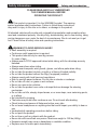
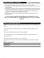
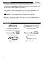
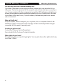
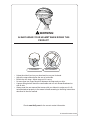
Owner’s Manual for 16” Slider This manual contains important safety, assembly, operation and maintenance information. Please read and fully understand this manual before operation. Save this manual for future reference. HSlider 16in EN 103112 m0046 Copyright Huffy Corporation 2012 Owner’s Manual Index Your Slider: • Safety Information ................................................................................. 3 • Owner’s Identification Record................................................................ 4 Assembly: • Introduction ............................................................................................ 5 • Tools Needed ......................................................................................... 5 • Parts Assembly View ............................................................................. 6 • Parts Assembly List ............................................................................... 7 • Rear Frame Installation ......................................................................... 8 • Handlebar Installation ............................................................................ 8 • Rear Tire and Axle Installation ............................................................... 9 • Seat Installation .................................................................................... 10 • Front Wheel Installation ........................................................................ 11 • Pedal Installation .................................................................................. 12 • Brake Setup .......................................................................................... 13 Maintenance and Service: • Maintenance ......................................................................................... 16 • Tires ..................................................................................................... 16 Huffy Warranty: • Limited Warranty................................................................................... 18 2 Safety Information • Safety and Introduction PLEASE READ AND FULLY UNDERSTAND THIS OWNERS MANUAL BEFORE OPERATING THE PRODUCT This symbol is important. It is the WARNING symbol. The warning symbol precedes safety instructions. Failure to follow these instructions may result in injury to the rider or to others, or damage to the product. All wheeled vehicles will provide safe, enjoyable transportation and recreation when used and maintained properly. Like bicycling, skateboarding, and in-line skating, riding can be dangerous even under the best of circumstances. We do not want you to get hurt. Please follow all safety rules and operating instructions. WARNING TO AVOID SERIOUS INJURY: Adult assembly is required. Continuous adult supervision is required. This product should only be used by persons 5+ years of age. Always wear a CPSC approved helmet while riding, with the chinstrap securely fastened. Always wear shoes when riding. Always wear kneepads, wrist guards, gloves, and elbow pads when riding. Do not ride the product at dusk, at night or at times of limited visibility. Do not ride the product without the flag (if equipped) installed. Always comply with local laws and regulations. Ride on smooth paved surfaces. Do not ride on streets or roadways. Do not ride off road, on grass or wet surfaces. Never use near motor vehicles. Do not ride the product over curbs or bumps that can damage the steering mechanism. Do not ride on hills, steeply sloped areas, on or near steps, near swimming pools, or in alleys. Not intended for jumping. The brake may be hot after continuous use. Do not touch after braking. Check brakes and secure all fasteners before every ride. Do not wear headphones or anything else that would impair your ability to hear or see. Understand all operating procedures before riding. Do not push the product. Do not tow or pull any objects with the product. Never ride with more than one person. Maximum weight is 150 lbs (68Kg). Excessive weight may cause a hazardous or unstable condition. Replace worn or broken parts immediately. 3 Safety Information - continued • Safety and Introduction Know your limits. Be familiar with your abilities. Use common sense. Not suitable for children under 3 years as foam pieces may break off and cause a choking hazard. Handlebar hand grips and tube end plugs should be replaced if damaged, as bare tube ends have been known to cause injury. It is particularly important that bicycles and tricycles used by children are checked regularly to ensure that adequate protection for the ends of the handlebars are in place. Replacement forks must have the same rake and tube inner diameter as the original product. IF YOU HAVE ANY QUESTIONS REGARDING THE OPERATION OF THIS PRODUCT, PLEASE REFER TO THIS OWNERS MANUAL OR CALL CUSTOMER SERVICE. Owner’s Identification Record NOTE: This information is only available on the product itself. It is not available from Huffy. Each Huffy product has a Model printed on the label and a serial number on the product. Write these numbers below to keep for future reference. You will need this number if you order parts or request service information from Customer Service. Write this number below to keep it for future reference. If the product is stolen, give this number and a description of the product to the police. Model / Serial Number: Purchase Date: Model Name: 4 • Assembly Introduction It is important to read this entire manual before beginning assembly. If the unit has any parts that are not described in this manual, look for separate “Special Instructions” that are supplied with the product. Do not dispose of the carton and packaging until you complete the assembly of the unit. This can prevent accidentally discarding parts of the product. WARNING: Keep small parts away from children during assembly. NOTE: All of the directions (right, left, front, rear, etc.) in this manual are as seen by the rider while seated on the unit. Tools Needed 5 Small Adjustable Wrench (Jaws must open at least 9/16 inch.) Open-end Wrenches Flat-blade Screwdriver Phillips Screwdriver Slip-Joint Pliers Metric Allen Wrenches 6 2-5 2-4 2-3 Parts Assembly View 2-1 2-2 1-2 1-4 1-9 3-1 1-6 1-5 4-2 1-1 1-3 4-3 1-10 3-2 4-4 1-7 4-3 4-2 1-8 4-1 4-5 7 Description Main Frame Rear Frame Handlebar Frame Bolts M8 x 62mm (x2) Washer 8mm (x2) Nut M8 (x2) Handlebar Bolts M8 x 28mm (x2) Washer 8mm (x2) Washer 8mm x 17mm (x2) Handlebar Pad Rear Wheel (x2) Rear Axle Washer (x2) Nut (x2) Cap (x2) Seat No. 1-1 1-2 1-3 1-4 1-5 1-6 1-7 1-8 1-9 1-10 2-1 2-2 2-3 2-4 2-5 3-1 Parts Assembly List 4-5 4-4 4-3 4-2 4-1 3-2 No. Left Side Pedal Right Side Pedal Washer 5mm (x4) Fork Screws M5 x 12mm (x4) Front Wheel Assembly Seat Bolts M6 x 32mm (x4) Description 8 1-2 1-2 13mm X 2 1-9 5mm 1 1-6 1-6 1-9 1-9 X 2 1-6 1-5 1-5 X 2 1-4 X 2 1-5 1-4 1-4 1-9 1-9 1-4 1-4 5mm 1-1 1-6 1-6 1-5 1-5 1-1 1-3 1-3 WARNING: Frame and Handlebar bolts must be sufficiently tightened to ensure they do not come loose. X 2 1-7 1-8 1-8 1-7 1-7 1-10 1-10 X 2 1-8 6mm 6mm Rear Frame and Handlebar Installation • Assembly 9 2-3 2-3 FINAL STEP 2-5 2-5 2-4 2-4 2 2-1 2-1 WARNING: Nuts must be fully tightened by using sockets on nuts at both ends of axle. 2-1 2-1 1-2 1-2 2-3 (x 2) 2-3 2-2 2-2 2-4 (x 2) 2-4 5mm 13mm FINAL STEP 2-5 2-5 Rear Tires and Axle Installation • Assembly 3 10 1-1 1-1 3-1 3-1 3-2 3-2 5mm 5mm 3-2 X 4 3-2 Seat Installation • Assembly 11 A B C A 5 Turn Unit Upside Down This will allow the tire to fit between the brake pads. 1. Squeeze Brake Levers together (A). 2. Pull Brake Cable (B) out of Holder (C). 4 6 R WARNING: Tighten all screws to ensure wheel does not come loose. 4-3 4-3 4-2 X 4 4-2 4-3 X 4 4-3 4-2 4-2 2 1 L NOTE: Ensure the front wheel is installed correctly so that when pedaled the unit moves forward. Front Wheel Installation • Assembly 12 WARNING: Pedals must be sufficiently tightened to ensure they do not come loose. • The pedal marked “R” has right hand threads. Insert it into the crank arm on the right side. Tighten it in a clockwise direction. • The pedal marked “L” has left hand threads. Insert it into the crank arm on the left side. Tighten it in a counterclockwise direction. • Make sure both pedals are threaded fully into the crank arm. Tighten the pedals to ensure they will not come loose. NOTE: There is a pedal marked “R” and a pedal marked “L”. 7 R 15mm x 10mm L Pedal Installation • Assembly • Assembly Brake Setup 2 1 3 4 B E E D 0 A C A 5 C B Installing Front Brake Cable: 1. Insert brake cable barrel into brake lever groove (Step 1 and 2). 2. Turn barrel nut so slot is away from brake lever slot (Step 3). Tighten. 3. Squeese the two Brake Levers together (A). 4. Insert the Brake Cable Guide (B) into the cutout in the Guide Bracket (C). 5. Make sure the Brake Cable Guide (B) is seated securely in the Guide Bracket (C) cutout. 6. Make sure there is no gap at Brake Lever (D) and that both Sheaths (E) are fully seated. 13 • Assembly Brake Setup - continued C B D A WARNING: You must adjust the front brakes before you ride the bicycle. Step One: Put the brake shoes (B) in the correct position: Loosen the Screw (A) of each Brake Shoe (B). Adjust each Brake Shoe so it is flat against the rim and aligned with the curve of the rim. Make sure each Brake Shoe does not rub the tire. If the surface of the Brake Shoe has arrows, make sure the arrows point toward the rear of the bicycle. Hold each Brake Shoe in position and tighten the Screw. Step Two: Test the tightness of each Brake Shoe: Try to move each Brake Shoe out of position. If a Brake Shoe moves, do Step 1 again, but tighten the nut tighter than before. Do this test again, until each Brake Shoe does not move. 14 • Assembly Brake Setup - continued A E F D C G 1/16” 1/16” H B Step One: Put the brake shoes the correct distance from the rim: 1. If needed, adjust Brake Levers (G) to a comfortable distance from the grip using the Adjustment Screw (H). Turning the screw IN brings it closer to the grip. 2. Make sure brake line Sheaths (A, B) are seated correctly. 3. Position each Brake Shoe 1/16 inch away from the rim: 4. Turn the caliper brake adjusting Screws (D) in or out to make the adjustment. 5. If the brake shoes cannot be positioned the correct distance from the rim, hold both Brake Shoes against the rim and loosen the cable clamp Screw (E) 6. Squeese the Brake Arms (F) together and pull or loosen the cable wire slightly. 7. Tighten the cable clamp Screw. Step Two: Check the tightness of the cable clamp: Squeeze the brake lever with firm pressure. Make sure the cable does not move in the cable clamp. WARNING: Do not overtighten the cable clamp. overtightening the cable clamp may cut the cable and cause brake failure. Check the brake for proper operation by spinning the wheel, and applying the brake a few times. If the brake does not operate properly, repeat the procedure. 15 Maintenance • Maintenance Periodic maintenance is required to ensure the product continues to operate properly. If any part of the product does not operate properly – discontinue use. Keep the product clean and free of dirt, dust and water. This will prolong the useful life of the product. Check all screws and fasteners, re-tighten any that are loose. Replace any fasteners that are damaged. WARNING: If anything does not operate properly, discontinue use. Tires Maintenance: • Frequently check the tire inflation pressure because all tires lose air slowly over time. For extended storage, keep the weight of the bicycle off the tires. • Do not use unregulated air hoses to inflate the inner tubes. An unregulated hose can suddenly over inflate tires and cause them to burst. • Replace worn tires. WARNING: Do not ride or sit on the unit if a tire is under inflated. This can damage the tire and inner tube. Rear Tires: Note: The hard plastic rear wheels are designed for stability and safety. The wear rate of these plastic wheels depends on the surface the product is used on, and the severity of use. Inflating the Front Tire: • • • • Use a hand or a foot pump to inflate the tire. Service station meter-regulated air hoses are also acceptable. The maximum inflation pressure is shown on the tire sidewall. If two inflation pressures are on the tire sidewall, use the higher pressure for onroad riding and the lower pressure for off-road riding. • The lower pressure will provide better tire traction and a more comfortable ride. Before adding air to any tire, make sure the edge of the tire (the bead) is the same distance from the rim, all around the rim, on both sides of the tire. If the tire does not appear to be seated correctly, release air from the inner tube until you can push the bead of the tire into the rim where necessary. Add air slowly and stop frequently to check the tire seating and the pressure, until you reach the correct inflation pressure. (See Figure next page) continued >> 16 Tires - continued Tire Bead NOT Seated Correctly 17 • Maintenance Tire Bead Seated Correctly Limited Warranty • Warranty Information • Part or model specifications are subject to change without notice. • This Limited Warranty is the only warranty for the product. There are no other express warranties. • The only uses for this product are described in this manual. Warranty registration is not required. • The Limited Warranty extends only to the original consumer and is not transferable to anyone else. What does this Limited Warranty cover? This Limited Warranty covers all parts of the product except the rear wheels, which have no warranty. What must you do to keep the Limited Warranty in effect? This Limited Warranty is effective only if: • the product is completely and correctly assembled; • the product is used under normal conditions for its intended purpose (see the following section for excluded activities); • the product receives all necessary maintenance and adjustments. What is not covered by this Limited Warranty? This product is designed for general transportation and recreational use only. This Limited Warranty does not cover normal wear and tear, normal maintenance items, or any damage, failure, or loss that is caused by improper assembly, maintenance, adjustment, storage, or use of the product. This Limited Warranty will be void if the product is ever: • used in any competitive sport; • used for stunt riding, jumping, aerobatics or similar activity; • installed with a motor or modified in any other way; • ridden by more than one person at a time; • rented; • used in a manner contrary to the instructions in the literature supplied with the product. Huffy will not be liable for incidental or consequential loss or damage due directly or indirectly from use of this product. Some States do not allow the exclusion or limitation of incidental or consequential damages, so the above limitation may not apply to you. 18 Limited Warranty - continued • Warranty Information For how long does this Limited Warranty last? The frame is warranted for life except aluminum frames which are warranted for ten (10) years. The fork is warranted for life except for shock forks which are covered by a one (1) year warranty. All other components (except the LED, batteries and plastic rear wheels) are warranted against manufacturing defects for six (6) months from the date of purchase. LEDs have a one (1) month warranty. Batteries and plastic rear wheels are not warranted. What will Huffy do? Huffy will replace, without charge to you, any frame, fork, or component found to be defective by Huffy. The original owner must pay all labor and transportation charges connected with the repair or warranty work. How do you get service? Contact the Customer Service Department. See included list for Customer Contact information. What rights do you have? This warranty gives you specific legal rights. You may also have other rights which vary from State to State. 19 WARNING: ALWAYS WEAR YOUR HELMET WHEN RIDING THIS PRODUCT! CORRECT INCORRECT • • • • • Helmet should sit level on your head and low on your forehead Adjust the strap sliders below the ear on both sides. Buckle the chin strap. Adjust strap until it is snug. No more than two fingers should fit between the strap and your chin. A proper fitting helmet should be comforable and not rock forward/backward or side to side. • Always read the user manual that comes with your helmet to make sure it is fitted and attached properly to the wearer’s head according to the fitting instructions described in the user manual. Check www.Huffy.com for the current contact information H Helmet EN 100212 i0027