1
United States Patent [191
[11] Patent Number:
[45] Date of Patent:
Cain et al.
[54]
SERIAL DATA FRAME GENERATOR FOR
TESTING TELECOMIVIUNICATIONS
CIRCUITS
[75] Inventors: Christopher B. Cain; Robert E.
McAuliffe; Lynn A. Schmidt; Elaine
L. May, all of Loveland; John E.
Siefers, Fort Collins, all of Colo.
Alto, Calif.
[56]
through 5-10 and 4-148 through 4-151, Apr. 1987.
CCITT, The International Telegraph and Telephone,
Consultative Committee, Digital Networks-Transmis
sion Systems and Multiplexing Equipment, 1985, pp.
Manual, vol. 1: System Reference, HP part number
03065-90090, Aug. 1987, Chapters 7, pp. 7-1-7-17; 9,
[21] Appl. No.: 179,373
Apr. 8, 1988
[22] Filed:
[58]
OTHER PUBLICATIONS
Siemens, Telecommunications, Data Book 1987, pp. 5-2
85-94.
Hewlett-Packard Journal, Oct. 1984, pp. l-35.
Hewlett-Packard 3065X/L Board Test System Users’
[73] Assignee: Hewlett-Packard Company, Palo
[51]
[52]
4,967,412
'Oct.30, 1990
Int. Cl.5 ..................... .. G01R 31/28; G06F 11/00
U.S. Cl. ................................ .. 371/20.1; 371/20.4;
371/27
Field of Search ............... .. 371/27, 22, 20.1, 20.4,
371/27; 364/200, 900; 375/10; 379/1
References Cited
U.S. PATENT DOCUMENTS
pp. 9-1-9-72; 23, pp. 23-1-23-40
Primary Examiner-Charles E. Atkinson
Attorney, Agent, or Firm-Christopher J. Byrne
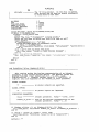
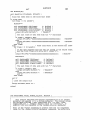
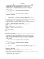
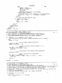
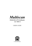
[57] -
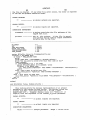
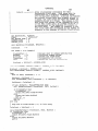
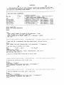
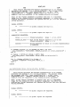
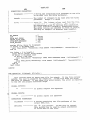
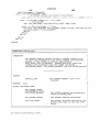
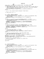
ABSTRACT
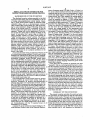
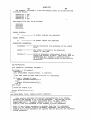
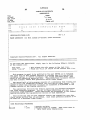
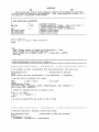
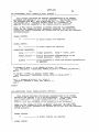
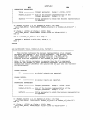
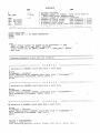
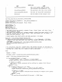
Disclosed is a serial frame generator which generates
serial data which conforms to a user-selected telecom
munication protocol. The serial frame generator can be
used with a circuit board tester to create test vectors for
4,450,560 5/ 1984 Conner ................................ .. 371/27
.. 371/27
4,451,918 5/1984 Gillette ................. ..
371/27
4,507,576 3/1985 McCracken et a1.
4,517,661 ' 5/1985
Graf et a1. ............ ..
4,555,663 1l/1985
Shimizu ............................... .. 371/27
telecommunications circuits which require serial data
input. The serial frame generator is user-adaptable so
that serial frame data can be produced for essentially
any kind of serial frame protocol.
371/27
3 Claims, 10 Drawing Sheets
p 130
150
FORMAT
FILE
PATTERN CAPTURE
FCRMAT
(PCF)
GENERATOR
PCF OUTPUT FILE
(VCL COMPATIBLE PCF
SOURCE CODE)
US. Patent
Oct.30, 1990
Sheet 1 of 10
Gm; WE XE
GE
F
m ; 2925 .
mgzo m/
4,967,412
US. Patent
0111.30, 1990
ANALOG
Sheet 2 of 10
; I l
SIGNAL
4,967,412
//
"
II
{I
-
50
11 11 11 11
10101010
DIGITAL
-
SERIAL DgA
_
FRAME
-
(T1)
\
101 01 010
(56
O
FRAMING
8-BIT
8-BIT
B-BIT
BIT
CHANNELO
CHANNEL1
'
~ '
'
pc1‘ '11’
I10)
:11’
I10]
I11’.
VCL COMPATIBLE
end 10f
PCF SOURCE CODE
59
PC
repeat 185 times
\
'
execute NulLb'It
end repeat
FIG 2
'
'
CHANNEL 23
US. Patent
Oct.30, 1990
Sheet 4 of 10
4,967,412
US. Patent
Sheet 6 of 10
Oct. 30, 1990
4,967,412
START
FRAME GENERATION
SUBROUTINE
280
cREATE FILE
28-‘
FRAME DATA FILE /
130
I
CONVERT DATA 286
FROM STEP 258 /
AND/0R 264 T0
FRAME FORMAT
I
PRINT BITS
288
T0
/
FRAME DATA FILE 130
290
YES
NO
CLOSE
FRAME DATA FILE /
130
@5
FIG 4B
US. Patent
0¢t.30, 1990
Sheet 7 of 10
4,967,412
@E
m
fom
“muUsmo mwozasw
US. Patent
Oct. 30, 1990
om?26E252E.E “UI P
Sheet 9 0f 10
4,967,412
GE<w
_‘owv IZQPo
US. Patent
Oct. 30, 1990
Sheet 10 of 10
4,967,412
/ 175
! Format file for D/A CODEC text
I The PCF order is:
I
I
+-> Vatid_data
I
|+-> Data_bit
l
!
!
“XX”
PCF vector contains two bits
I
i
Following is a “Pcfgen” command-it specities“d_a_dota ?os the
i frame data hie to he react;“x”is the dummy character to replace
I
!
in the PCP vectors
l
l
1 Program Section (contains VCL and PCF statements)
“111/
‘:10’,
“101/
“101/
“10!!
“111/
end pct
“111/
repeat 185 times
execute NutLbit
end repeat
pct
I110’!
“11”I/
\\
“101/
‘it:
end pct
repeat 185 times
execute Nult_bit
FIG 6B
4,967,412
'
1
2
SERIAL DATA FRAME GENERATOR FOR
ductor Company model TP 3064 Codec. A Codec is a
T1 circuit which interfaces between the network and a
TESTING TELECOMIVIUNICATIONS CIRCUITS’
telephone and serves to convert analog signals to digital
BACKGROUND OF THE INVENTION
The disclosed invention relates generally to the ?eld
of circuit board testing and more speci?cally to the art
of testing telecommunications circuit boards. Gener
ally, a given circuit board consists of numerous semi
conductor chips, such as a microprocessor, memory
tizing process, the Codec samples the analog signal at
the rate of '8 KHz. Thus, for instance, eight samples
would be required to digitize a l KHz analog signal.
(A/D) and digital signals to analog (D/A). In the digi
chips, counter chips, control chips, etc., laid out accord
ing to some interactive design. Following design and
layout of the circuit board, it is necessary to test the
board to ensure that all the chips, as laid out, perform as
These eight samples would be inserted in the same chan
nel position of eight consecutive T1 frames. The general
procedure for digitizing a given analog signal with a
Codec is as follows: (1) generate the voltage sample of
the sine wave for each sampling interval of time; (2)
convert the voltage sample to the appropriate pulse
code modulated (PCM) eight bit code, that is, digitize
the sample; (3) insert the eight bit digitized sample value
expected. Testing will involve application of test-vec 15
tors to pins of a given chip (or cluster of chips) on the
into the proper channel position of a 24~channel T1
board. A test-vector for a given chip (or cluster of
frame; (4) repeat steps 1 through 3 for the next sample
chips) generally consists of a binary word having an
value. This procedure, however, becomes exceedingly
“input” portion and an “output” portion. The goal in
tedious and time consuming, even for relatively “sim
testing is to determine if the application of the input 20 ple” signals like a sinusoidal frequency. For instance,
portion of a test-vector produces an output matching
sampling a 1010 Hz signal at a sampling rate of 8 KHz
the output portion of the test-vector. If there is a match,
would require 800 samples before the samples would
the test is successful (pass). Unsuccessful tests (failure)
begin to repeat themselves. These 800 samples would be
indicate defective board design, defective layout or
inserted in the same channel position of 800 consecutive
defective chips. Test-vectors will be supplied by the 25 Tl frames. This amounts to 800x l93= 154,400 bits of
designer of the circuit board (usually with the aid of a
information which would be necessary to test a Codec
computer-aided~design (CAD) system). The test-vec
to determine if it properly digitized a 1010 Hz signal. In
tors will be chosen so as to pinpoint problems on the
addition, the PCM analog-to-digital conversion process
board, if they exist.
may require application of a complex transfer function.
Actual circuit board testing is performed with the aid 30 (See the International Telegraph and Telephone Con
of a circuit board testing machine. Circuit board testing
sultative Committee (CCITT) Red Book, Vol. III, Fas
machines are well known in the prior art. For example,
cicle III.3, Tables la/G.71l & 1b/G.71l (A-law) and
a well known circuit board testing machine is the Hewl
2a/G.7ll & 2b/G.7ll (Mu-law).) Finally, this informa
ett-Packard Company model HP-3065 circuit board
tester. The HP-3065, for instance, has 264 pins which 35 tion must be converted (one bit at a time) to the corre
can be simultaneously selectively connected to various
pins of a given circuit board for application of test-vec
tors to the board and the monitoring of board output
generated in response. The HP-3065 is fully described in
the October 1984 issue of the Hewlett-Packard Journal.
sponding test pattern language which the given circuit
board tester requires.
It has been prior art practice to generate such data
“manually”, that is, a test programmer has had to calcu
late the necessary serial frame test data and transform it
into test pattern language information which the given
With the aid of a circuit board tester, whole sequences
circuit board tester can accept. Thus, for a given serial
of test-vectors are applied to the board under test. In
device, the test programmer must generate the sample
fact, it is not uncommon for test-vector listings to be
data, generate the serial frames from the sample data,
thousands of test-vectors long where each test-vector is
dozens of bits in width. Typically, such test-vectors are 45 and then generate the test data from the serial frames.
Obviously, generating such large amounts of complex
applied, sequentially one test vector at a time, in parallel
telecommunication serial frame test data is tedious and
to the circuit board under test.
Telecommunication circuit boards, however, present
a special problem in circuit board testing: serial data
protocols. Essentially all modern telecommunication
time consuming. (Generating such test data “manually”
could very well consume weeks of an individual’s time.)
50 Moreover, ensuring the accuracy of the test data is very
dif?cult and to the extent that there are doubts about the
schemes obey some sort of serial data protocol, such as
accuracy of the test data, the test results are suspect.
the X25 (HDLC) protocol for wide area networks, the
The result has been that prior art testing of complex
telecommunications circuits has been limited by the
protocol, and so forth. Common to all such protocols is 55 difficulty of generating suf?cient amounts of accurate
serial frame test data.
the organization ‘of information in the form of serial
frames. The protocol de?nes the structure of the frame.
SUMMARY OF THE INVENTION
Consider, for instance, the 24-channel U.S. Tl tele
The
present
invention provides for quick and accu
phone protocol: analog voice signals are sampled and
rate generation of serial frame test data for telecommu
the samples are digitized; each digitized sample consists
nications circuit boards. Through software, the present
of one byte of information; samples are grouped in a
invention performs the major steps of (l) generating the
24-channel serial frame; each frame is 193 bits long
data; (2) generating the serial frames from the data; and
consisting of a lead framing bit followed by 24 bytes,
(3) generating the test data from the serial frames. Al
where each byte is a single sample from a given chan
Integrated Services Digital Network ISDN S-Bus pro
tocol (CCITT 1.430), the 24-channel U.S. Tl telephone
nel. Communication over the T1 systems occurs via 65 though the present invention could be easily adapted to
transmission of T1 frames.
A typical T1 circuit which may require testing is a T1
coder-decoder (Codec), such as the National Semicon
work with essentially any modern circuit board tester, it
has been implemented on the HP-3065 circuit board
tester machine and it will therefore be described in
3
4,967,412
4
The VCL-compatible PCF source code, that is, the
PCF Output File, may be compiled, linked and exe
cuted by the HP-3065._ Thus, the present invention al
guage which has been adapted for use on board test
lows the HP-3065 user to quickly specify and generate
machines and dubbed BT-BASIC. BT-BASIC is well
serial data frames for the testing of telecommunications
known in the prior art and is fully explained in connec
circuits. The invention allows for high programmer
tion with the HP~3065 instruction manual.
productivity as well as providing adaptability so that
The ?rst major step of generating digital data is per
the programmer can write applications for his/her indi
formed by a so-called Serial Frame Generator. The
vidualized needs. The prior art alternative to the pres
Serial Frame Generator includes: a Data Generator; a
collection of Data Generation/Conversion (DG/C) 10 ent invention is “manual” coding, which would require
connection with the HP-3065. The invention is imple
mented using a form of the BASIC programming lan
routines and user-written Data Files; and a Frame Gen
signi?cant programmer time in calculating complex
erator. The Data Generator produces the digital data
ther reading data from a user-written Data File or gen
serial frames and checking them for accuracy. The
present invention, therefore, enables the circuit board
testing programmer to produce large amounts of com
erating data by executing a given DG/C routine. The
DG/C routines produce the digital data representative
prehensive and accurate serial frame test data which
would simply be too tedious and/or time consuming to
manual, Vol. I: System Reference.) The PCF Generator
been sampled at regular intervals Box 53 shows digital
which is representative of a given analog signal by ei
reasonably produce with prior art alternatives.
of single or multi-tone sine waves, pseudo-random bit
sequences (such as a 511 bit error rate (BER) signal),
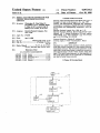
BRIEF DESCRIPTION OF THE DRAWINGS
CCITT G.711 reference and noise signals, and CCITT
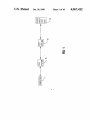
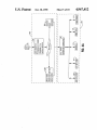
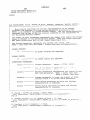
FIG. 1 shows a schematic diagram of a circuit board
PCM A-law and Mu-law conversions. In addition, the 20
testing machine such as would be used with the present
Data Generator and DG/C routines are written in an
invention.
open systems manner so that the user can customize an
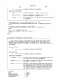
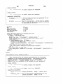
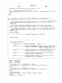
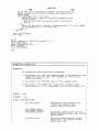
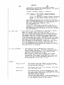
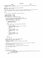
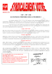
FIG. 2 shows a step-wise ?ow diagram of the present
original DG/C to produce a particular kind of data.
invention.
The second major step of generating the serial frames
FIG. 3 shows a schematic diagram of the present
from the digital data is also performed by the Serial 25
invention.
Frame Generator. In addition to the Data Generator
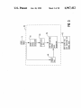
FIG. 4 shows a schematic diagram of Serial Frame
and DG/C routines, the Serial Frame Generator in
Generator 125 of FIG. 3.
cludes a Frame Generator. The Frame Generator con
FIG. 4A shows a blow-up of Data Generator 200 of
verts the data produced by the Data Generator into
FIG. 4.
serial frames which obey a user-selected telecommuni
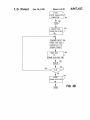
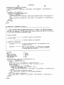
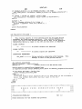
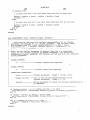
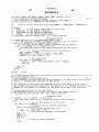
FIG. 4B is a blow-up of box 267 of FIG. 4A.
cations protocol. Among the framing options available
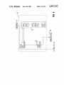
FIG. 5 shows a schematic diagram of PCF Generator
to the user are l—chatmel, 24-channel and 32-channel Tl
150 of FIG. 3.
frames, X.25 (HDLC) frames, ISDN frames, and vari
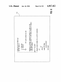
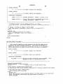
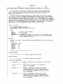
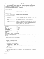
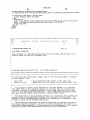
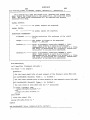
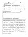
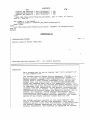
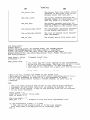
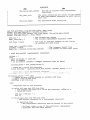
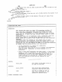
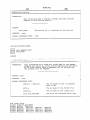
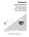
FIG. 6 shows an example of Format File 140.
ous Siemens frames. (See the 1987 Siemens Telecommu
FIG. 6A shows the contents of the d a data ?le of
nications Data Book.) In addition, the Frame Generator 35
FIG. 6.
is also written in an open systems manner so that the
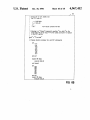
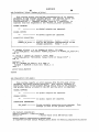
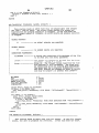
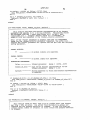
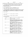
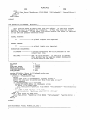
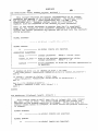
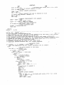
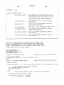
FIG. 6B shows an example of a PCF Output File 175
user can add framing options. Output from the Frame
which has been derived from the Format File 140 of
Generator is stored in a so-called Frame Data File.
FIG. 6 and the Frame Data File 130 of FIG. 6A.
The third and ?nal major step of generating the cir
FIG. 7 shows pseudo code which shows how Parser
cuit board test data from the serial frames is performed
300 and PCF Source Code Generator of 350 process
by a Pattern Capture Format (PCF) Generator. (PCF is
Format File 140 and Frame Data File 130, respectively,
explained in Chapter 7 of the HP-3065 X/L user’s man
to produce PCF Output File 175.
ual, Vol. III: Advanced Technologies Testing-Reference
and Syntax) The PCF Generator has two input files: the
DESCRIPTION OF THE PREFERRED
Frame Data File and a so-called Format File. As noted, 45
EMBODIMENT
the Frame Data File is the output of the Frame Genera
FIG. 1 shows a schematic diagram of a circuit board
tor. The Format File is a user-written ?le containing
testing machine such as would be used with the present
executable VCL code together with instructions for
invention. Computer 5, Test Station 10 and Test Fixture
merging the data in the Frame Data File with the exe
15 comprise the circuit board testing machine, such as
cutable VCL code to produce an executable PCF Out
the HP_-3065 circuit board tester. The object of testing is
put File. “VCL” stands for “Vector Control Lan=
the Device Under test (DUT) 20. DUT 20 is a circuit
guage”. VCL is a feature of the HP-3065 circuit board
board, and in particular a telecommunications circuit
tester. VCL is a high-level language which is compiled,
board. Computer 5 controls the interaction of Test Sta
linked and executed by the HP-3065 computer. VCL
allows a programmer to operate the HP-3065 with 55 tion 10 and test Fixture 15 in the testing of the DUT 20.
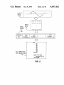
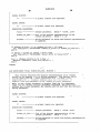
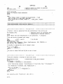
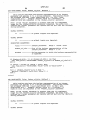
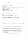
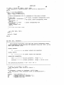
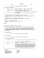
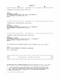
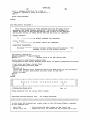
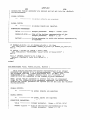
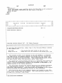
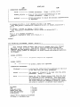
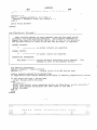
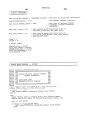
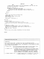
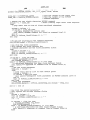
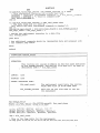
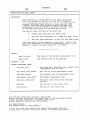
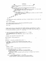
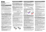
FIG. 2 shows a step-wise flow diagram of the present
source-code-like programming instructions. (VCL is
invention. Box 50 shows an analog signal which has
fully explained in chapter 23 of the HP-3065 X/L user’s
data conversions of such samples. Box 56 shows a serial
frame protocol. The digitized samples from box 53
which generates VCL-compatible source code. The
would be inserted into the serial frame format of box 56.
Format File is the input ?le to the Parser. The Frame
The serial frame(s) of box 56 are then converted into
Data File is the input ?le to the PCF Source Code
VCL-compatible PCF source code, as shown in box 59.
Generator. The Parser processes the syntax information
The code in box 59 would be directly executable by an
in the Format File and issues commands to the PCF
Source Code Generator. The PCF Source Code Gener 65 HP-3065 circuit board tester. Note in box 59 that the
serial frame data (which would be used as stimulus input
ator processes the Frame Data File together with the
to a telecommunications circuit board under test) is
output of the Parser to produce the PCF Output File
included directly within the PCF code. It should be
containing VCL-compatible PCF source code.
includes a Parser and a PCF Source Code Generator
5
4,967,412
6
S-Bus (CCITT 1.430) protocols will reside in memory
noted that FIG. 2 is in fact schematic: the present inven
tion does not actually sample and digitize an analog
structure 210 in user written Data Files. Typically, data
signal. Rather, the digital information, which is repre
sentative of digitized analog samples (as shown in box
53), is either read from a ?le or generated directly by
for the remaining protocols will be generated with a
given DG/C routine. Given the user selected protocol
and the appropriate data (either generated with a
the present invention. This digital data is then inserted
DG/C or read from a user-written Data File), Frame
Generator 250 formats the data into serial frames con
forming to the selected protocol. The serial frames are
then stored in Frame Data File 130. As noted above, the
into a user-selected serial frame protocol format, as
shown in box 56. As shown in box 56, a given serial
frame protocol format will have de?ned ?elds. Box 56
shows a 24-channel Tl frame having a lead framing bit
present invention is implemented in software in the
followed by 24 8-bit data channel ?elds. (Typically,
BT-BASIC programming language. The BT-BASIC
when testing a telecommunications circuit with serial
frames, certain frame ?elds will remain constant from
implementation of Serial Frame Generator 125 is listed
in Appendices A and B. Appendix A contains the BT
frame to frame while other ?elds, such as a given chan
nel in a T1 frame such as channelo, will vary with each
BASIC code for Data Generator 200 and Frame Gener
ator 250. Appendix B contains the BT-BASIC code for
the DG/C routines.
FIG. 4A shows a blow-up of Data Generator 200 of
FIG. 4. As shown in box 255, Data Generator 200 re
ceives input requesting “N” number of serial frames
frame. Thus, the generated digital data (as represented
by box 53) will typically be inserted in the variable
frame ?elds while the constant ?elds will simply be
repeated from frame to frame.) The serial frames are
then converted into VCL-compatible PCF source code 20 conforming to a given protocol. (“N” is an integer.)
as shown in box 59. The PCF source code, like VCL,
Depending upon the protocol, Data Generator 200 will
can be compiled, linked and executed by the HP-3065.
obtain framing data either by reading data from the
FIG. 3 shows a schematic diagram of the present
appropriate user-written Data File(s) and/or by execut
invention. The user will input a request on an HP-3065
ing the appropriate DG/C routine(s). (Recall that the
for serial frame data with which to test a given telecom 25 user-written Data File(s) and the DG/C routine(s) re
munications circuit board. User Input 75 is processed by
Serial Frame Generator 125. User Input 75 will specify
the type of data for which serial framing is required and
side in memory structure 210 of FIG. 4.) Typically, the
protocols which will require user written Data Files are
the following: X.25 (HDLC), RS232 and the ISDN
the protocol to which the serial frame data must con~
S-Bus (CCITT 1.430). Typically, the protocols which
form. Serial Frame Generator 125 generates the actual 30 will have one or more DG/C routine are the following:
serial frames which conform to User Input 75. These
l-channel, 24-channel and 30-channel Tl protocols; and
serial frames will then be stored in Frame Data File 130.
the Siemens IOM and SLD protocols. There is also a
User Input 75 will also include a user-written Format
ninth option: the preferred embodiment of the present
File 140. The Format File 140 is a user-written ?le
invention provides a template whereby the user can
containing executable VCL code together with instruc 35 write his/her own protocol framing subroutine. Given
tions for merging the data in the Frame Data File 130
“N”, the user-requested number of serial frames, and
with the executable VCL code to produce an execut
able PCF Output File 175. Frame Data File 130 and
Format File 140 are input ?les to Pattern Capture For
mat (PCF) Generator 150. Obeying the merge instruc
tions in Format File 140, PCF Generator 150 merges
the serial frame data from Frame Data File 130 with the
executable VCL code in Format File 140 to produce
the o user’s choice of protocol for the frames, data is
generated by Data Generator 200 and an appropriate
protocol implementation program of Data Generator
200 and Frame Generator 250 is called. In the preferred
embodiment of the present invention, the implementa
tion programs are written in the BT-BASIC program
ming language, although essentially any programming
PCF Output File 175 containing VCL-compatible PCF
language could be used. The BT-BASIC code imple
source code which is executable by the HP-3065. An
example of such a PCF Output File 175 is shown in box
59 of FIG. 2.
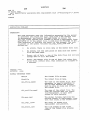
FIG. 4 shows a schematic diagram of Serial Frame
Generator 125 of FIG. 3. Serial Frame generator 125
includes Data Generator 200, memory structure 210 50
mentation of Data Generator 200 and Frame Generator
250 for each protocol (including a user de?nable tem
containing DG/C routines and Data Files, and Frame
Generator 250. As noted above, User Input 75 will
plate) is listed in Appendix A. The implementations as
listed in Appendix A are shown in Table l. The imple
mentations are quite self-explanatory. Note also that for
each protocol, Frame Generator 250 will call a given
Frame Generation Subroutine, as shown in box 267.
Each Frame Generation Subroutine in turn will call the
specify the particular telecommunications protocol to
subroutines GetBitsMSB (box 269), GetBitsLSB (box
which the desired serial frame data must conform. In
271), OpenFile (box 273), PrintBits (box 275) and possi
the preferred embodiment of the present invention, 55 bly FGen13 Error (box 277). The Frame Generation
eight widely followed protocol options are available as
Subroutines corresponding to each protocol are listed
well as a general template option with which the user
Table 2 below. The subroutines called by the Frame
can tailor a protocol that is not among the eight options.
Generation Subroutine of box 267 are also explained
Depending upon the protocol chosen (or tailored) by
and de?ned in Appendix A as listed in Table 2.
the user, serial frame data will either be generated with
TABLE 1
a given DG/C routine or read from a given Data File.
BT-BASIC Protocol Implementations
(Appendix A page numbers in parentheses)
The eight framing protocol options available in the
preferred embodiment of the present invention are as
follows: l-channel, 24-channel and 30-channel Tl
PROTOCOL
frames, Siemens IOM and SLD frames, serial RS232 65 1. x.2s (HDLC)
frames and X25 (HDLC) frames, and the ISDN S-Bus
protocol conforming to the CCITI' 1.430 standard.
Typically, data for the RS232, the X25 and the ISDN
2.
3.
4.
5.
RS232
l-channel T1
24-channel T1
30-channel T1
IMPLEMENTATION
FRAMEJDLC (30-44)
FRAME__RS232 (54-62)
FRAME_1CI-I (1-9)
FRAME_24CH (10-19)
FRAME_30CH (2o-29)
4,967,412
7
TABLE l-continued
code together with instructions for merging the data in
BT-BASIC Protocol Implementations
[AEEndiX A page numbers in parentheses!
PROTOCOL
IMPLEMENTATION
6.
7.
8.
9.
FRAMEJOM (44-53)
FRAME._SLD (62-71)
FRAME_SBUS (83-94)
Siemens IOM
Siemens SLD
ISBN S-Bus (CCI'IT 1.430)
user de?nable protocol
Frame Data File 130 with the executable VCL code to
produce an executable PCF Output File 175. As noted
above, “VCL” stands for “Vector Control Language”.
VCL is a feature of the HP-3065 circuit board tester.
VCL is a high-level language which is compiled, linked
and executed by the HP-3065 computer. VCL allows a
FRAME-TEMPLATE (72-80)
template
programmer to operate the HP-3065 with source-code
10
Parser 300 and a PCF Source Code Generator 350
QApmndix A page location in parentheses!
PROTOCOL
SUBROUTINE
1.
2.
3.
4.
5.
6.
7.
8.
9.
Generate__hdlc (32)
Generate__rs232 (55)
Generate__lch (2)
Generate_24ch (12)
Generate_30ch (22)
Generate-mm (46)
Generate_sld (64)
Generate_sbus (83)
GenerateJrame (74)
X.25 (HDLC)
RS232
l-channel Tl
24-channel Tl
SO-channel Tl
Siemens IOM
Siemens SLD
ISDN S~Bus (CCIT 1.430)
user de?nable protocol
like programming instructions. (VCL is fully explained
in chaper 23 of the HP-3065 X/L user’s manual, Vol. 1:
System Reference). The PCF Generator includes a
TABLE 2
Protocol Frame-Generation-Subroutines
template
8
user. Format File 140 will contain executable VCL,
'
which generates VCL-compatible source code. User
15 written Format File 140 is the input ?le to the Parser
300. Frame Data File 130 is the input ?le to the PCF
Source Code Generator 350. Parser 300 processes the
syntax information in the Format Dile 140 and issues
commands to PCF Source Code Generator 350. PCF
20
Source Code Generator 350 processes Frame Data File
130 together with the output of Parser 300 to produce
the PCF Output File 175 containing VCL-compatible
PCF source code. A complete explanation of the opera
tion of PCF Source Code Generator 350 together with,
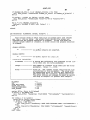
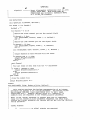
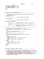
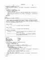
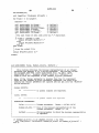
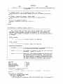
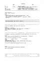
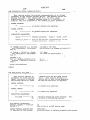
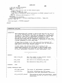
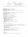
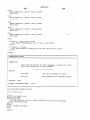
FIG. 4B is a blow-up of box 267 of FIG. 4A. A given 25 prescriptions of Format File 140 syntax is contained in
Frame Generation Subroutine, such as Generate__24ch,
Chapter 1 of HP-3065 X/L user’s Manual, Vol. III,
is called in box 280. In box 282 a counter variable is
Rev. C pages 9-62 through 9-70. An implementation of
initialized to zero. Frame Data File 130 is then created
PCF Source Code Generator 350 in the BT-BASIC
in box 284. The data to be formatted into a frame will
programming language is listed in Appendix D.
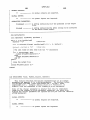
have been produced by Data Generator 200, either by 30 FIG. 6 shows an example of Format File 140. Format
invocation of a DG/C and/or reading from a user-writ
File 140 is written by the user. Instructions for writing
ten Data File. In the preferred embodiment of the pres
the Format File are listed in Chapter 9 of HP-3065 X/L
ent invention, the data produced by Data Generator 200
user’s Manual, Vol. III, Rev C. As shown in FIG. 6, the
will reside in a “temp-?le” in main memory in computer
Format File has two sections: a header section and a
35
5. In box 286, the ?rst line of such data is inserted into
program section. The header section lines are indicated
a given frame format as dictated by the user-chosen
by leading “l” characters. The program section' is the
protocol. The frame information generated in box 286 is
remaining part of the Format File and contains VCL
then written to Frame Data File 130. The counter vari
and PCF statements. (Recall that PCF is explained in
able is then incremented in box 290. A check is made in
chapter 7 of the 3065 X/L user’s manual, Vol. III, and
diamond 292 to see if the number of frames (N) re
VCL is explained in chapter 23 of the 3065 X/L user’s
quested by the user have been written. If not, the pro
manual,
Vol. I.). The lines beginning with the character
cess loops back to box 286 and the next line of data in
“l” are comment lines in VCL. However, a line begin
the “temp-?le” is formatted into a frame. On the other
ning with “l##” is a replacement command to the PCF
hand, when the “N” frames requested by the user have
been generated and written to Frame Data File 130, 45 Generator. The “!##” command will specify a replace
ment character and the name of a Frame Data File 130.
then Frame Data File 130 is closed.
In
FIG. 6, the PCF command line is: !##M “"'” “d13
As noted above, Data Generator 200 either reads data
from a user written Data File or produces data by in
voking DG/C routines. In the preferred embodiment of
the present invention, the DG/C routines are also im
plemented in the BT-BASIC programming language.
The DG/C routine BT-BASIC implementations are
listed in Appendix B. The DG/C, routines are also
described and explained in Chapter 9 of HP-3065 X/L
user’s Manual, Vol. III, Rev. C, sections 9.4.3 through
9.4.12.
FIG. 5 shows a schematic diagram of PCF Generator
150 of FIG. 3. PCF Generator 150, merges data with a
programming language to produce a ?le which is di
rectly executable by computer 5. In the preferred em
bodiment of the present invention, PCF Generator 150
a_data”. The asterisk (‘) is the replacement character
and d_a_data is the name of the Frame Data File 130.
The command tells the PCF Generator to replace the
asterisk with data from the d_a_data ?le wherever the
asterisk occurs in the PCF code in the program section
of the Format File. The PCF code is bounded by the
statements pcf and end pcf in the program section.
FIG. 6A shows the contents of the d_a_data ?le of
FIG. 6. The d_a_data ?le is the Frame Data File 140.
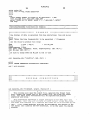
FIG. 6B shows an example of a PCF Output File 175
which has been derived from the Format File 140 of
FIG. 6 and the Frame Data File 130 of FIG. 6A.
FIG. 7 shows pseudo-code which shows how Parser
300 and PCF Source Code Generator of 350 process
Format File 140 and Frame Data File 130, respectively,
) has two input ?les: data is contained in Frame Data File
to produce PCF Output File 175. Parser 300 detects the
130 and a programmable language is contained in For
“!##” line in Format File 140, reads the name of the
mat File 140. The data in Frame Data File 130 may be
supplied by the user or it can be generated by Serial 65 Frame Data File 130, and associates that name with the
replacement character (the “"’ in FIG. 6).
Frame Generator 125. Format File 140 is written by the
4,967,412
9
10
TABLE OF CONTENTS
APPENDIX A
FRAME_VICH
_
FRAME_IOM
sub Ggigagiglch
5 FRAME_RS232
I R‘ ‘M
sub Generate__24ch
FRAME_30CH
sub Generate__3och
FRAME_HDLC
FRAME_SLD
_
FRAME_TEMPLATE
sub Generate-frame
1O FRAME_SBUS_TE
sub Generate_hd1c
sub Generate._Sbus_TE
I /TElECOM/GEN/FRAME_1CH
Rev 3.0
I
1 FRAME GENERATOR
for simple one time’ slot ( channel ) pcm generator
I
I
I
I
I
I
I
I
I
I
I
I
..
I Copyright Hewlett-Packard 1987.
All Rights Reserved.
I
***‘k********************-k***'k********1:*'k*****'k**~£*******~k******~k**-k************
I
I
I
I To add other DSP subroutines, simply type in the following BTBasic commands
I at the command line:
I
edit 9999
I This places the edit cursor at the last line.
I
I
merge I'file id"
I Merge the "file id" source at the current edit line.
I
I
g
I
This program is meant to be modified by the user BEFORE it is executed.
The first half of this program consists of routines that fill pre-definsd
I variables (arrays or numeric variables) with values from data files, user
I entry or DSP subroutine generated data. These predefined variables reflect
I the data field(s) within this particular serial frame format.
I
I
The second half of this program consists of a subroutine that formats the
I
I values within the predefined variables into this serial frame format. The
I manner in which the predefined variables are formatted is discussed in the
comment section of the framing subroutine.
I
g
The subroutines following the framing subroutine are standard throughout
1
g the frame generator programs. Not all of these subroutines are used in a
1 particular frame generator. These subroutines are documented in the comment
I
section proceding the implementation section of each subroutine.
I
I
I
This allows the user to have complete- control and flexibility over data
field values and how they are generated. Each frame generator program is to
I be used for a different frame format.
I
1
1
I USER MODIFIABLE PARAMETERS
I
I
MAX_LE2N
II
0
I Scratch variable .
1000
I Maximum number of frames.
I
LEN
dim CH(1000)
I
= O
Same value used in
data field array dimensioning.
I Default number of frames to generate.
J‘
Channel field array.
4,967,412
11
12
print using "9"
pr‘nt "ONE ("w-“NEIL
GENERATOR"
print
print
loop
I
input "Enter number of frames to be generated : ",LEZN
exit if (LEN >= 1) and (LEN < MAX_LEN)
print "VALUE OUT OF RANGE, RANGE = l . .";MAX__LEN;", RE'I'RY"
end loop
l*************'k*****************************************************i****~k******
I Retrieve/Generate field data for frame(s)
J.’
5
I***t********************************************-k**************i~k**************
i
.III I IIII IIII II II II II II III1II
E X A M P L E
I 1II III IIIII I II IIIII I1I1 II I I I II 1
One channel of data is generated from dsp subroutines: tone and mu_law
print
input "Enter the tone frequency?iz) to be generated : ",Frequency
I
i use rms value to produce full range
I
VRMS
Phase
8159 / sqr(2)
II
1 for MU__LAW
o
SampFrequency = 8000
call Tone( VRMS, Frequency, Phase, SampFrequency, LEN, CH(*) )
call MU_law( LEN, CH(*) )
I
I be sure to merge TONE and MU__LAW at end of test
I
call Generate_lch( "chlaffile", LEN, CH(*) )
print
print "FRAME GENERATOR SUCCESSFV‘ULLY COMPLETED"
end I main program
I!!!
.
.
.
.
.
.
.
.
.
.
.
.
.
.
.
.
.
.
.
.
.
.
.
.
.
.
.
.
.
.
.
.
.
.
.
.
.
.
.
.
.
.
.
.
.
.
.
.
.
.
.
.
.
.
.
.
.
.
.
.
.
.
.
.
.
.
.
.
.
.
.
.
.
.
..
.
-
-
.
.
.
.
.
.
-
-
~
-
-
-
-
-
-
-
-
.
.
1111
III!
PROGRAM
SUBROUTIN'ES
I I I I
l I l I
.
a
-
¢
o
-
-
.
a
-
-
I
-
-
a
~
.
~
-
.
.
.
.
-
.
-
.
-
-
u
-
.
a
~
.
-
-
o
-
-
-
-
-
-
-
-
.
-
-
.
-
.
.
-
-
-
-
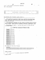
sub Generate__lch( FileName$, Length, Channel(*) )
1
This routine will open the output file, generate the framed field
data, output the framed data to the output file, and close the output
file. Any fatal error encountered will be reported and program
execution will stop.
'
This subroutine reproduces a single time-slot of bit data for a pcm
data stream. Each time-slot consists of eight boclean values WEB-0E8.
rfhe other bits required for a complete pcm frame are to be provided by the
user .
‘Liliise ' rrame stuffing’ bits may be provided by VCL vectors in'the
PCP format file (used by the PCP Generator) , or by the users VCL digital
program.
'"
4,967,412
13
14
For example, if length = 4 and the Channel array is filled with the
following values:
Channel(0) = 128
Channel(l) = 255
Channel(2) = 0
Channel(3) = 255
“r
The output file will be as follows:
10000000;
A
11111111;
00000000;
11111111,‘ ?
GLOBAL OUTPUTS:
""
----------- -- no global outputs are exported.
GLOBAL INPUTS:
""
----------- —- no global inputs are imported.
SUBROUTINE PARAMETERS:
FileName$
containing file pathname of the output
—————— -
1 e.
Length --------- —- The number of frames to be generated.
Range = 1. .MAX___I..EI\T
Channel(*) ————— —- Array id parameter containing 8 bit (0. .255)
single pcm“ channel of data. This array must be
dimensioned as a single(l) dimension array
of 0 to MAX__LEN elements prior to calling this
subroutine.
dim Buffer$[80]
call OpenFile( FileName$, @FilePtr )
for Frame = O to Length-l
Buffer$=""
call GetBitsMSB( Channel (Frame) , 8, Buffer$ )
I
l The last frame of data ends with two ";" characters
I
if Frame = (length-1) then
output @Fi1ePtr;Buffer$,-"; ;"
else
output
@FilePtr;Buffer$;"~;,"/"
if
_
"
"
end
next Frame
'
I
! close the output file
I
assign @FilePtnEi-"ror to
A.
subend
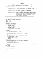
sub GetBitsMSB( Value, Number__of_bits, Buffer$ )
This routine retrieves the boolean representation of an integer
parameter and appends it to a string parameter. The boolean values
are stripped from MSB ( most significant bit ) to 1.58 ( least
significant bit ) . Example: decimal value 23 =."0OOlO1l1", 1f
eight(8) bits are requested in the <Number_of_bits> parameter.
Note: If the <Value> parameter is greater than the 2's complement
range for the <Number_of__bits> parameter requested, the extra bits
withing the <Value> parameter are ignored and not put into the <Buffer$>
string parameter.
-
'
4,967,412
15
16
GLOBAL OUTPUTS:
global outputs are exported.
GIDBAL INPUTS:
----------- --=- no global inputs are imported.
n n
SUBROUTINE PARAMETERS:
Value ---------- -- Integer parameter.
Range = -32768. .32767
Number__of_bits --- Size of the boolean representation of the
integer parameter. Range = l. .16
Buffer$ ———————— —- String parameter to which the boolean representation
is appended.
if (Number__of_bits < 1) or (Number_of_bits > 16) then
call FGen_Error( "GetBitsMSB: Number__of_bits<1 or Number_of_bits>l6" )
end if
-
'
if (Value < -32768) or (Value > 32767) then
__
call FGen_Error( "GetBitsMSB: Value<—32768 or Value>32767" )
end if
'
for I = (Number_of bits-l) to 0 step -1
Buffer-S = Buffer§ & val$( bit( Value, I ) )
next I
subend
sub GetBitsLSB( Value, Number_'of_bits, Buffer$ )
This routine retrieves the boolean representation of an integer
parameter and appends it ‘to a string parameter. The boolean values
are stripped from 158 ( least significant bit ) to MSB ( most
significant bit ) .
Exa...p1e: decimal value 23 = "11101000" ,
I
if
eight(8) bits are requested in the <Number_of_bits> parameter.
Note: If the <Value> parameter is greater than the 2's complement
range for the <Number__of_bits> parameter requested, the extra bits
withing the <Value> parameter are ignored and not put into the <Buffer$>
string parameter.
GLOBAL OUTPUTS:
----------- -- no global outputs are exported.
GLDBAL INPUTS:
----------- -- no global inputs are imported.
SUBROUTINE PARAMETERS:
Value —————————— —- Integer parameter.
Range = -32768. .32767
Number_of__bits --- Size of the boolean representation of the
integer parameter. Range = 1. .16
Buffer$ ———————— -- String parameter to which the boolean representation
is appended.
4,967,412
17
18
if (Number__of_bits < l) or (Number_of_bits > 16) then
call FGen_Error( "GetBitsLSB: Number__of_bits<1 or Number_of_bits>l6" )
I end if
if (Value < —32768) or (Value > 32767) then
call FGen_Error( "GetBitsLSB: Va1ue<-32768 or Value>32767" )
end if
for I = O to (Number_of_bits-1)
BufferS = BufferS & val$( bit( Value, I ) )
next I
subend
sub ReadArray( FileNameS, Iength, Array(*) )
g This routine reads an ASCII text file of integer data (one integer
per line ) into an array. Any errors found during file access are
reported and the program execution is stopped. If the file does not
contain Length number of integers, an error occurs and program execution
is stopped.
GLOBAL OUTPUTS :
""
--?- ———————-- no glo’Eakoutputs are exported.
GLOBAL INPUTS:
""
----------- -— no global inputs are i;npc_,;2;_._d,
S LYBROUI IN E PARH-ZE'I'ERS :
“
FileNameS -------- -— A string the containing file pathnamebf the file
to be read into the Array parameter.
Length ----------- —- The number of integers to be read into the Array
parameter.
Array ———————————— —— Array id.
' Range = 1. .32766
-
The integer values read from the file
are returned in this parameter.
The array must
be dimensioned prior to calling this subroutine.
The array must be a single(l) dimensioned array.
The array indices are assumed to start at zero(0)
and stop at Length-l or greater than Length-1.
NO_ERROR
= 0
EOF
= 101007
FILE_NOT_FOUND
WRONG__FILE_TYPE
= 100009
= 101015
FILE__NOT_ASSIGNED
= 136
FILE_EXISTS
= 275
~
assign @File, Error to FileName$
if Error <> N0_ERROR then
call F‘Gen_Error( "ReadArray: FILE ERROR "'&FileName$&"' "&errm$(Error) )
end if
for Index = O to length-l
enter @File, ,Error; Array(Index)
if Error <> N0_ERROR then
if Error = EOF then
call FGen_Error( "ReadArray: MORE DATA EXPECTED FROM ’"&Fi1eName$&"’" )
else
call FGen__Error("ReadArray: FILE ERROR '"&FileName$&"’ "&errm$(Error) )
end if
end if
next Index
,