1
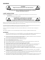
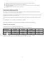
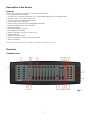
SM-8/2
ORDERCODE 50700
Congratulations!
You have bought a great, innovative product from Showtec.
The Showtec SM-8/2 brings excitement to any venue. Whether you want simple plug-&-play action or a
sophisticated DMX show, this product provides the effect you need.
You can rely on Showtec, for more excellent lighting products.
We design and manufacture professional light equipment for the entertainment industry.
New products are being launched regularly. We work hard to keep you, our customer, satisfied.
For more information: [email protected]
You can get some of the best quality, best priced products on the market from Showtec.
So next time, turn to Showtec for more great lighting equipment.
Always get the best -- with Showtec !
Thank you!
Showtec
Showtec SM-8/2™ Product Guide
Warning..…...................................................................................…………………………………………..................
Safety-instructions…………………………………………………………………………………….…......................
Operating Determinations…………………………………………………………………………….......................
Return Procedure……………………………………………………………………………......................................
Claims…………………………………………………………………………….........................................................
2
2
3
4
4
Description..…..............................................................................……….……………………………….…................
Features…….……………………………………………………………………………………….……....…................
Overview………………………………………………………………………………………………………................
Controller front....................................................................................................................................................
Controller backside...........................................................................................................................................
5
5
5
5
7
Installation...............................................................................…...……………………………………..…..................
Installation....................................................………………………………………..………....................................
Common Terms...........................................………………………………………..………....................................
7
7
8
Set Up and Operation.....................................................................……..…………………………….…...................
- RESETTING THE SYSTEM……………………….....................................................………..............................
- Fixture Addressing…………………….....................................................………........................................
- Physical fader Assignment (OPTIONAL SETUP) ....................................................……….......................
- Reverse Channel Output (OPTIONAL SETUP) ....................................................……….........................
- Fade Time Assign (OPTIONAL SETUP) ....................................................………......................................
Programming……………....................................................................................……….....................................
- Entering program mode........................................................................……….......................................
- Create a scene........................................................................................................................................
- Edit a scene..............................................................................................................................................
- Scene copy ..............................................................................................................................................
- Delete scene ............................................................................................................................................
- Delete all scenes......................................................................................................................................
- Bank copy ................................................................................................................................................
- Bank delete ..............................................................................................................................................
Chase Programming..........................................................................................................................................
- Create a chase........................................................................................................................................
- Copy Bank Into Chase ............................................................................................................................
- Adding a step to a chase........................................................................................................................
- Delete a scene/step in a Chase ............................................................................................................
- Delete a Chase ........................................................................................................................................
- Delete all Chase Programs .....................................................................................................................
Playback (scenes)..............................................................................................................................................
- Manual run scene.....................................................................................................................................
- Running in Sound-Mode ..........................................................................................................................
- Running in Auto-Mode ............................................................................................................................
- Blackout ....................................................................................................................................................
Playback (chases)..............................................................................................................................................
- Manual run chases...................................................................................................................................
- Auto run chases .......................................................................................................................................
- Music run chases .....................................................................................................................................
- Running Sequential chases ....................................................................................................................
MIDI OPERATION.................................................................................................................................................
9
9
9
9
10
10
10
10
11
11
11
11
11
11
11
12
12
12
12
12
12
12
13
13
13
13
13
13
13
13
13
13
14
Maintenance.................................................................................………..………….…….…………….................... 15
Troubleshooting............................................................................………………….………………….…................... 15
Product Specifications.................................................................……………….…….…………………................... 16
1
WARNING
CAUTION!
Keep this device away from rain and moisture!
FOR YOUR OWN SAFETY, PLEASE READ THIS USER MANUAL CAREFULLY
BEFORE YOUR INITIAL START-UP!
SAFETY INSTRUCTIONS
Every person involved with the installation, operation and maintenance of this device has to:
be qualified
follow the instructions of this manual
CAUTION! Be careful with your operations.
With a dangerous voltage you can suffer
a dangerous electric shock when touching the wires!
Before your initial start-up, please make sure that there is no damage caused by transportation. Should
there be any, consult your dealer and do not use the device.
To maintain perfect condition and to ensure a safe operation, it is absolutely necessary for the user to
follow the safety instructions and warning notes written in this manual.
Please consider that damages caused by manual modifications to the device are not subject to
warranty.
This device contains no user-serviceable parts. Refer servicing to qualified technicians only.
IMPORTANT:
The manufacturer will not accept liability for any resulting damages caused by the nonobservance of this manual or any unauthorized modification to the device.
Never let the power-cord come into contact with other cables! Handle the power-cord and all
connections with the mains with particular caution!
Never remove warning or informative labels from the unit.
Do not open the device and do not modify the device.
Do not insert objects into air vents.
Do not connect this device to a dimmerpack.
Do not switch the device on and off in short intervals, as this would reduce the device’s life.
Only use device indoor, avoid contact with water or other liquids.
Avoid flames and do not put close to flammable liquids or gases.
Always disconnect power from the mains, when device is not used or before cleaning! Only
handle the power-cord by the plug. Never pull out the plug by tugging the power-cord.
Make sure that the device is not exposed to extreme heat, moisture or dust.
Make sure that the available voltage is not higher than stated on the rear panel.
Make sure that the power-cord is never crimped or damaged. Check the device and the powercord from time to time.
If device is dropped or struck, disconnect mains power supply immediately. Have a qualified
engineer inspect for safety before operating.
If the device has been exposed to drastic temperature fluctuation (e.g. after transportation), do
not switch it on immediately. The arising condensation water might damage your device. Leave
the device switched off until it has reached room temperature.
If your Showtec device fails to work properly, discontinue use immediately. Pack the unit securely
(preferably in the original packing material), and return it to your Showtec dealer for service.
2
Repairs, servicing and electric connection must be carried out only by Showtec.
For replacement use fuses of same type and rating only.
This device falls under protection class I. Therefore it is essential to connect the yellow/green
conductor to earth.
WARRANTY: Till one year after date of purchase.
OPERATING DETERMINATIONS
This device is not designed for permanent operation. Consistent operation breaks will ensure that the
device will serve you for a long time without defects.
If this device is operated in any other way, than the one described in this manual, the product may suffer
damages and the warranty becomes void.
Any other operation may lead to dangers like short-circuit, burns, electric shock, lamp explosion, crash
etc.
You endanger your own safety and the safety of others!
Improper installation can cause serious damage to people and property !
Connection with the mains
Connect the device to the mains with the power-plug.
Always pay attention, that the right color cable is connected to the right place.
International
EU Cable
UK Cable
US Cable
Pin
L
BROWN
RED
YELLOW/COPPER
FASE
N
BLUE
BLACK
SILVER
NUL
YELLOW/GREEN
GREEN
GREEN
EARTH
Make sure that the device is always connected properly to the earth!
3
Return Procedure
Returned merchandise must be sent prepaid and in the original packing, call tags will not be issued.
Package must be clearly labeled with a Return Authorization Number (RMA number). Products returned
without an RMA number will be refused. Highlite will not accept the returned goods or any responsibility.
Call Highlite 0031-455667723 or mail [email protected] and request an RMA prior to shipping the fixture.
Be prepared to provide the model number, serial number and a brief description of the cause for the
return. Be sure to properly pack fixture, any shipping damage resulting from inadequate packaging is the
customer’s responsibility. Highlite reserves the right to use its own discretion to repair or replace
product(s). As a suggestion, proper UPS packing or double-boxing is always a safe method to use.
Note: If you are given an RMA number, please include the following information on a piece of paper
inside the box:
1) Your name
2) Your address
3) Your phone number
4) A brief description of the symptoms
Claims
The client has the obligation to check the delivered goods immediately upon delivery for any shortcomings and/or visible defects, or perform this check after our announcement that the goods are at their
disposal. Damage incurred in shipping is the responsibility of the shipper; therefore the damage must be
reported to the carrier upon receipt of merchandise.
It is the customer's responsibility to notify and submit claims with the shipper in the event that a fixture is
damaged due to shipping. Transportation damage has to be reported to us within one day after receipt
of the delivery.
Any return shipment has to be made post-paid at all times. Return shipments must be accompanied with
a letter defining the reason for return shipment. Non-prepaid return shipments will be refused, unless
otherwise agreed in writing.
Complaints against us must be made known in writing or by fax within 10 working days after receipt of the
invoice. After this period complaints will not be handled anymore.
Complaints will only then be considered if the client has so far complied with all parts of the agreement,
regardless of the agreement of which the obligation is resulting.
4
Description of the device
Features
The SM-8/2 is a light controller from Showtec and features:
• Universal DMX-512 controller
• Controls up to 192 DMX channels; up to 12 intelligent lights with 16 channels each
• 30 banks of 8 scenes, 240 scenes max
• 6 sets of chases containing 240 scenes
• Fog & strobe control buttons
• Patch mode: Each fixture free assignable channels
• Programmable Speed and Fade time
• Reversible sliders
• Sequential linking of chases
• Re-assignable channels
• Music-controlled, tap-sync and auto run
• Polarity selector
• 3HE (3U) 19" rack mount
• Output connector: 3 and 5 pole XLR female
• MIDI compatible
NOTE: Knowledge of DMX and Midi is required to fully utilize this unit.
Overview
Controller Front
Fig. 1
5
1) Scanner select buttons
To select scanners for setting, programming or recording.
2) Scanner indicator
LED's Indicates the fixtures currently selected
3) Strobe button + LED
Used for Showtec strobes.
4) Page A Indicator
LED represents Ch 1~8 range selected
5) Page B Indicator
LED represents Ch 9~16 range selected
6) Scene select buttons
Universal bump buttons representing scene location for storage and selection
7) Channel faders
For adjusting DMX values, Ch 1~8 can be adjusted immediately, after pressing the respective scanner
select button, Ch 9~16 after pressing the Page select button
8) LCD display window
Status window displays pertinent operational data
9) Mode Indicator
LED’S Provides operating mode status, (manual, music or auto)
10) Midi/Add button
Activates MIDI external control and also used to confirm the record/save process
11) Program button
Activates program mode.
12) Bank Up / Down button
Press the Up/Down button to select from 30 banks.
13) Chase buttons
Chase memory 1 ~ 6; These buttons are used for activating the chase of programmed scenes.
14) Blackout button
Press this button to enable or disable relevant DMX output. When its LED is lit, that means the relevant
DMX output is disabled. Press this button again the LED will be “off”, that means the DMX output is
reactivated.
15) Fog button + Heat Ready LED
This button is used to control the Fog machine. Relevant LED will show you the working state (READY).
16) Reverse Channel LED
Indicates reverse channel programming mode
17) Fade LED
Indicates fade programming mode
18) Page select button
Used to select page between Page A (I-8) and Page B (9-16).
19) Speed fader
This will adjust the hold time of a scene or a step within a chase (range of 0.1 second to 10 minutes).
20) Fade Time fader
Used to adjust the fade time. Fade time is the amount of time it takes for a scanner (or scanners) to
Move from one position to another, for the dimmer to fade in or fade out.
21) Auto/Del button
Activates Music mode or to delete scenes or chases during programming
22) Music/Bank Copy button
Activates Music mode or as the copy command during programming
23) Tapsync/Display button
Used to create a standard beat or to change the value mode between % and 0-255.
6
Controller Backside
Fig. 2
24) MIDI input port for external triggering of banks, scenes, chases, and blackout using a MIDI device
25) DMX polarity switch May be used to change signal polarity
26) DC Input jack Main power feed
27) Strobe connector Showtec Mono Strobe ¼” connector for built in strobe controller
28) Fog connector Showtec fog controller jack mono
29) ON/OFF power switch Turns the controller on and off
30) 3-pin DMX output connector
31) 5-pin DMX output connector
Installation
Remove all packing materials from the SM-8/2. Check that all foam and plastic padding is removed.
Screw the equipment into a 19" rack. Connect all cables.
Always disconnect from electric mains power supply before cleaning or servicing.
Damages caused by non-observance are not subject to warranty.
7
Common Terms
The following are common terms used in intelligent light programming.
Blackout is a state where all lighting fixtures’ light output are set to 0 or off, usually on a temporary basis.
DMX-512 is an industry standard digital communication protocol used in entertainment lighting
equipment. For more information read Sections “DMX Primer” and “DMX Control Mode” in the Appendix.
Fixture refers to your lighting instrument or other device such as a fogger or dimmer which you can
control.
Programs are a number of scenes arranged one after another. It can be programmed as either a single
scene or multiple scenes in sequence.
Scenes are static lighting states.
Sliders are also known as faders.
Chases can also be called programs. A chase consists of a number of scenes arranged one after
another.
Scanner refers to a lighting instrument with a pan and tilt mirror; however DMX controllers can use this
term to control any DMX-512 compatible device as a generic fixture.
MIDI is a standard for representing musical information in a digital format. A MIDI input would provide
external triggering of scenes using midi devices such as a midi keyboard.
Stand Alone refers to a fixture’s ability to function independently of an external controller and usually in
sync to music, due to a built in microphone.
Fade slider is used to adjust the fade time between scenes within a chase.
Speed slider affects the amount of time a scene will hold its state. It is also considered a wait time.
Shutter is a mechanical device in the lighting fixture that allows you to block the lights path. It is often
used to lessen the intensity of the light output and to strobe.
Patching refers to the process of assigning faders to a DMX channel within a fixture.
Playbacks can be either scenes or chases that are directly called to execution by the user. A playback
can also be considered program memory that can be recalled during a show.
8
Set Up and Operation
Before plugging the unit in, always make sure that the power supply matches the product specification
voltage. Do not attempt to operate a 120V specification product on 230V power, or vice versa.
RESETTING THE SYSTEM
Warning: this will reset the controller to its factory defaults. This will erase all programs and settings.
1) Turn off the unit.
2) Press and hold BANK UP and AUTO/DEL.
3) Turn on power to the unit (while still holding BANK UP and AUTO/DEL).
Warning:
This will reset the controller to its factory defaults. This will erase all programs
and settings.
FIXTURE ADDRESSING
The SM-8/2 is programmed to control 16 channels of DMX per fixture. Therefore, the fixtures you
wish to control with the corresponding “SCANNER” buttons on the unit must be spaced 16 channels
apart (check the respective fixture’s manual for how to enter the information into the fixture).
Note: failure to use these DMX assignments may cause a lack of control of the fixtures.
PHYSICAL FADER ASSIGNMENT (OPTIONAL SETUP)
Use this feature to combine or unify fixture control attributes for different fixtures. For example; if you
were controlling 4 moving mirrors and 4 moving yokes, the color, gobo and dimmer channels may not
line up ideally on the physical faders. Use this function to re-assign the dimmer, color and gobo
channels to faders 1, 2 and 3. From now on you will be able to control the same attributes on all
fixtures using the same fader location.
1) Press and hold PROGRAM & TAPSYNC buttons together (1) time to access the channel assignment
mode.
2) Press a SCANNER button that represents the fixture whose faders you would like to re-assign.
3) Move the SPEED fader until you arrive at controller channel (number).
4) Move the FADE TIME fader to select the DMX channel.
5) Press the MIDI/ADD button to confirm setting.
6) Repeat steps 3 ~ 5 as often as necessary.
If you wish to copy a scanner’s physical assignments to another scanner, continue by following
steps 7-13. If you do not wish to do this, press and hold PROGRAM & TAPSYNC buttons (2) times to exit
mode.
Example: Copying Scanner 1 into Scanner 2
7) Press and hold SCANNER button # 1.
8) While holding button # 1 press SCANNER button # 2.
9) While holding SCANNER buttons # 1 and # 2, press and hold MIDI/ADD button.
10) Release SCANNER button # 1 first before releasing SCANNER button # 2.
11) Release MIDI/ADD button.
12) All SCANNER LED indicators will flash to confirm successful copy.
13) Press and hold PROGRAM & TAPSYNC buttons (2) times to exit mode.
9
REVERSE CHANNEL OUTPUT (OPTIONAL SETUP)
1) Press and hold PROGRAM & TAPSYNC buttons together (2) times to access the channel assignment
mode then press the SCANNER button.
2) Move the SPEED fader until you arrive at the controller channel you wish to alter.
3) Move the FADE TIME fader all the way up until N changes to Y.
If you wish to copy a scanner’s reverse channel assignments to another scanner, continue by following
steps 4-10. If you do not wish to do this, press and hold PROGRAM & TAPSYNC buttons (1) times to exit
mode.
Example: Copying Scanner 1 into Scanner 2
4) Press and hold SCANNER button # 1.
5) While holding button # 1 press SCANNER button # 2.
6) While holding SCANNER buttons # 1 and # 2, press and hold MIDI/ADD button.
7) Release SCANNER button # 1 first before releasing SCANNER button # 2.
8) Release MIDI/ADD button.
9) All SCANNER LED indicators will flash to confirm successful copy.
10) Press and hold PROGRAM & TAPSYNC buttons (1) times to exit mode.
FADE TIME ASSIGN (OPTIONAL SETUP)
You can choose whether the board’s fade time during scene execution is implemented broadly to all
output channels or only to the Pan and Tilt movement channels. This is relevant because often you
will want gobos and colors to change quickly while not affecting the movement of the light.
1) Turn OFF the controller.
2) Hold the BLACKOUT and TAPSYNC buttons simultaneously.
3) Turn ON the controller.
4) Press the TAPSYNC button to toggle between the two modes. Either all channels (A) or select channel
Pan & Tilt only (P)
5) Press BLACKOUT and TAPSYNC to save settings. All LED’s will blink to confirm.
10
Programming
A program (bank) is a sequence of different scenes (or steps) that will be called up one after another.
In the SM-8/2 30 programs can be created of 8 scenes in each.
ENTERING PROGRAM MODE
Press the PROGRAM button for 3 seconds until an LED dot next to the label PROG blinks. This indicates that
the user is in programming mode.
CREATE A SCENE
A scene is a static lighting state. Scenes are stored in banks. There are 30 bank memories on the
controller and each bank can hold 8 scene memories. The SM-8/2 can save 240 scenes total.
1) Press and hold the PROGRAM button for 3 seconds.
2) Select a SCANNER (fixture) to program.
3) Compose a look by moving the FADERS. (Changes in fixture attribute such as colors and gobos.)
Press PAGE SELECT to access Channels 9~16 on the faders.
4) To program another SCANNER press the SCANNER button you have just finished programming then
select another SCANNER button to program.
5) Repeat steps 2 ~ 4 until you have your look.
6) Tap MIDI/ADD button to prepare to store.
7) Choose a BANK (01~30). Use the Up and Down arrow Bank buttons to change if necessary.
8) Select a SCENES button to store. All LED's will blink 3 times. The display will now display the bank and
scene number that is stored.
9) Repeat steps 2 ~ 8 to record more scenes. ( Read Important notes on the right ->)
10) To exit program mode, hold the PROGRAM button for 3 seconds. The controller will default to a
BLACKOUT when exiting the programmer.
EDIT A SCENE
1) Press the PROGRAM button for 3 seconds.
2) Locate the scene in the program BANK. Use BANK UP/DOWN to navigate program banks.
3) Select the SCENE in the program BANK to edit.
4) Adjust FADERS to change the look.
5) Press the MIDI/ADD button then the SCENE button again previously selected for editing.
SCENE COPY
1) Press the PROGRAM button for 3 seconds.
2) Locate the scene in the program BANK. Use BANK UP/DOWN to navigate program banks.
3) Select the SCENE in the program BANK to copy.
4) Locate the destination scene in the program BANK. Use BANK UP/DOWN to navigate program banks.
5) Press the MIDI/ADD button then the new SCENE button to copy to.
DELETE SCENE
1) Locate the scene in the program BANK. Use BANK UP/DOWN to navigate program banks.
2) Press and hold the AUTO/DEL button while pressing the SCENE you want to delete.
DELETE ALL SCENES
1) Press and hold the PROGRAM button and the BANK while you turn the controller Off.
BANK COPY
1) Press the PROGRAM button for 3 seconds.
2) Locate the program BANK. Use BANK UP/DOWN to navigate program banks.
3) Press and release the MIDI/ADD button.
4) Locate the destination program BANK. Use BANK UP/DOWN to navigate program banks.
5) Press the MUSIC/BANK-COPY button to compete copy.
BANK DELETE
1) Press and hold the PROGRAM button for 3 seconds.
2) Locate the BANK to delete. Press the AUTO/DEL and MUSIC/BANK-COPY at the same time to delete
the Bank.
11
Chase Programming
A chase is created by using previously created scenes. Scenes become steps in a chase and can be
arranged in any order you choose. It is highly recommended that prior to programming chases for the
first time; you delete all chases from memory. See “Delete All Chases” for instructions.
CREATE A CHASE
A Chase can contain 240 scenes as steps. The term steps and scenes are used interchangeably.
1) Press and hold the PROGRAM button for 3 seconds.
2) Press the CHASE (1~6) button you wish to program.
3) Change BANK if necessary to locate a scene.
4) Select the SCENE to insert.
5) Tap the MIDI/ADD button to store. All LED’s will flash 3 times.
6) Repeat steps 3 ~ 5 to add additional steps in the chase. Up to 240 steps can be recorded.
7) Press and hold the PROGRAM button for 3 seconds to save the chase.
COPY BANK INTO CHASE
1) Press and hold the PROGRAM button for 3 seconds to enter programming mode.
2) Select the BANK to be copied using the BANK UP/DOWN buttons.
3) Press MUSIC/BANK COPY and Midi/Add buttons at the same time to copy.
4) Press and hold the PROGRAM button for 3 seconds to exit programming mode.
ADDING A STEP TO A CHASE
1) Press and hold the PROGRAM button for 3 seconds to enter programming mode.
2) Press the desired CHASE (1~6) button.
3) Press the TAPSYNC/Display and the display will display the scene and bank number. This displays the
scene you will be adding (STEP LED must be on),
4) Use the BANK UP/DOWN buttons to scroll through the chase and arrive at the step number for which
you would like to add or append a scene/step to.
5) Press MIDI/ADD button and one step number will be added to the previously displayed step number.
6) Press the SCENE button that corresponds to the scene to be copied.
7) Press MIDI/ADD button again to add the new step.
8) Press and hold the PROGRAM button for 3 seconds to exit programming mode.
DELETE A SCENE/STEP IN A CHASE
1) Press and hold the PROGRAM button for 3 seconds to enter programming mode.
2) Press the desired CHASE (1~6) button that contains the scene to be deleted.
3) Press the TAPSYNC/DISPLAY button to switch the LED display to steps.
4) Select the scene/step to be deleted using the BANK UP/DOWN buttons.
5) Press AUTO/DEL button to delete the step/scene.
6) Press and hold PROGRAM button for 3 seconds to exit.
DELETE A CHASE
1) Press and hold the PROGRAM button for 3 seconds to enter programming mode.
2) Press the CHASE button (1~6) to be deleted.
3) Press and hold the AUTO DEL button and the respective CHASE button then release to delete the
chase. All LED’s will blink 3 times.
DELETE ALL CHASE PROGRAMS
CAUTION! This procedure will result in irrevocable loss of chase step memory. The individual
scenes and program banks will be preserved.
1) Press and hold the BANK DOWN button and the AUTO DEL button while turning OFF the controller.
12
Playback (Scenes)
MANUAL RUN SCENE
When power is first turned ON, the controller will be in manual scene mode.
1) Make sure neither MUSIC TRIGGER nor AUTO TRIGGER LED's on the LED display are on.
2) Select the program BANK that stores the scene you want to run manually by using the BANK UP/DOWN.
3) Press the SCENE button to run.
RUNNING IN SOUND-MODE
1) Press the MUSIC/BANK-COPY button until the MUSIC TRIGGER LED turns on.
2) Change BANK programs by using BANK UP/DOWN buttons if necessary.
3) Press the MUSIC/BANK-COPY to exit.
RUNNING IN AUTO-MODE
1) Press and hold the AUTO DEL button until the AUTO TRIGGER LED turns on.
2) Change BANK programs by using BANK UP/DOWN buttons if necessary.
3) You can adjust the time between steps by moving the SPEED fader and the duration of the step by
moving the FADE TIME fader.
4) You can change Banks while in operation by using the BANK UP/DOWN buttons.
BLACKOUT
The Blackout button brings all lighting output to 0 or off (also called the home position of the unit).
Playback (Chases)
MANUAL RUN CHASES
This function allows the user to manually step through each individual step in a chase.
1) Press and hold PROGRAM button for 3 seconds to enter programming mode.
2) Start a chase by pressing any one of the CHASE buttons.
3) Press the TAPSYNC/DISPLAY button to manually step through the chase.
4) Use the BANK buttons to scroll through the chases.
5) Press and hold the PROGRAM button for 3 seconds to exit programming mode.
AUTO RUN CHASES
1) Press any one of the CHASE buttons.
2) Press and release the Auto / Del button. The corresponding LED will blink.
3) Adjust the SPEED and FADE faders to your liking.
4) You can override the speed and fade time by tapping the TAPSYNC/DISPLAY button (three) times. The
chase will now run on the interval time of the taps.
MUSIC RUN CHASES
1) Press any one of the CHASE buttons.
2) Press and release the MUSIC/BANK COPY buttons. The corresponding LED will blink in the display.
3) Your chase will now run to sound.
RUNNING SEQUENTIAL CHASES
1) Press either AUTO DEL or MUSIC BANK COPY buttons to select the trigger mode.
2) Press the CHASE button for each chase you wish to playback.
3) Adjust the Chase speed by changing the SPEED fader.
13
Midi Operation
The controller will only respond to MIDI commands on the MIDI channel when it is set to full stop. All
MIDI control is performed using Note on commands. All other MIDI instructions are ignored. To stop a
chase, send the blackout on note.
1) Press and hold the MIDI/ADD button until the third and fourth digits on the LED display blink.
2) Select the MIDI control channel (1~16) via the BANK UP/DOWN buttons to set.
3) Press and hold the MIDI/ADD button to store midi setup settings.
MIDI NOTE
00 to 07 Scenes
08 to 15 Scenes
16 to 23 Scenes
24 to 31 Scenes
32 to 39 Scenes
40 to 47 Scenes
48 to 55 Scenes
56 to 63 Scenes
64 to 71 Scenes
72 to 79 Scenes
80 to 87 Scenes
88 to 95 Scenes
96 to 103 Scenes
104 to 111 Scenes
112 to 119 Scenes
120 Chase 1
121 Chase 2
122 Chase 3
123 Chase 4
124 Chase 5
125 Chase 6
126 BLACKOUT
FUNCTION (TURN ON/OFF)
1~8 in BANK 1
1~8 in BANK 2
1~8 in BANK 3
1~8 in BANK 4
1~8 in BANK 5
1~8 in BANK 6
1~8 in BANK 7
1~8 in BANK 8
1~8 in BANK 9
1~8 in BANK 10
1~8 in BANK 11
1~8 in BANK 12
1~8 in BANK 13
1~8 in BANK 14
1~8 in BANK 15
14
Maintenance
The Showtec SM-8/2 requires almost no maintenance. However, you should keep the unit clean.
Disconnect the mains power supply, and then wipe the cover with a damp cloth. Do not immerse in
liquid. Do not use alcohol or solvents.
Keep connections clean. Disconnect electric power, and then wipe the DMX and audio connections
with a damp cloth. Make sure connections are thoroughly dry before linking equipment or supplying
electric power.
Troubleshooting
Showtec SM-8/2
This troubleshooting guide is meant to help solve simple problems. If a problem occurs, carry out the steps
below in sequence until a solution is found. Once the unit operates properly, do not carry out following
steps.
1. Fixture does not respond to controller: Check the DMX-address of the fixture and the controller.
Make sure they match. Make sure the connections are correct. Check if blackout is off.
2. Interference between chases; If the same channel is assigned to different running chases, the one
with the highest channel value will be put out.
3. Note: when in programming mode, as long as the LED indicator is lit, the value will be stored, even if
the value is zero.
4. Except for the channels assigned to the jog wheels and the channels set with slope, slope is not
assigned to the other channels.
5. For the master controlled channels, the master sliders are valid only when the dimmer buttons are
activated (LED indicator is on). If some channels can’t be controlled, please check if they are
assigned to master control.
6. If the device does not operate properly, unplug the device.
7. Check power from the wall, all cables, the fuse, the settings (return to default), etc.
8. If all of the above appears to be O.K., plug the unit in again.
9. If nothing happens after 30 seconds, unplug the device.
10. Return the device to your Showtec dealer.
15
Product Specification
Model: Showtec SM-8/2
Power Supply: DC 9Volt - 300mA
Power connector: Adapter included
Fixtures: 12 (each 16 channel)
Scenes: 240 (30 banks)
Chases: 6
Run mode: Auto, Music
Patch mode: Each fixture free assignable channels
Output: DMX-512 standard
Output connector: 3 and 5 pole XLR female
Dimensions: 535 x 195 x 100 mm
Weight : 2,92 kg
Design and product specifications are subject to change without prior notice.
Website: www.Showtec.info
Email: [email protected]
16