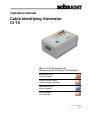
1
Operation manual Cable Identifying Generator CI TX Mess- und Ortungstechnik Measuring and Locating Technologies Elektrizitätsnetze Power Networks Kommunikationsnetze Communication Networks Rohrleitungsnetze Water Networks Leitungsortung Line Locating Issue: 4 (07/2009) ENG 3 Consultation with SebaKMT The present system manual has been designed as an operating guide and for reference. It is meant to answer your questions and solve your problems in as fast and easy a way as possible. Please start with referring to this manual should any trouble occur. In doing so, make use of the table of contents and read the relevant paragraph with great attention. Furthermore, check all terminals and connections of the instruments involved. Should any question remain unanswered, please contact: Seba Dynatronic Hagenuk KMT Mess- und Ortungstechnik GmbH Kabelmesstechnik GmbH Dr.-Herbert-Iann-Str. 6 D - 96148 Baunach Röderaue 41 D - 01471 Radeburg / Dresden Phone: +49 / 9544 / 68 – 0 Fax: +49 / 9544 / 22 73 Phone: +49 / 35208 / 84 – 0 Fax: +49 / 35208 / 84 249 E-Mail: [email protected] http://www.sebakmt.com SebaKMT All rights reserved. No part of this handbook may be copied by photographic or other means unless SebaKMT have before-hand declared their consent in writing. The content of this handbook is subject to change without notice. SebaKMT cannot be made liable for technical or printing errors or shortcomings of this handbook. SebaKMT also disclaim all responsibility for damage resulting directly or indirectly from the delivery, supply, or use of this matter. 4 Terms of Warranty SebaKMT accept responsibility for a claim under warranty brought forward by a customer for a product sold by SebaKMT under the terms stated below. SebaKMT warrant that at the time of delivery SebaKMT products are free from manufacturing or material defects which might considerably reduce their value or usability. This warranty does not apply to faults in the software supplied. During the period of warranty, SebaKMT agree to repair faulty parts or replace them with new parts or parts as new (with the same usability and life as new parts) according to their choice. SebaKMT reject all further claims under warranty, in particular those from consequential damage. Each component and product replaced in accordance with this warranty becomes the property of SebaKMT. All warranty claims versus SebaKMT are hereby limited to a period of 12 months from the date of delivery. Each component supplied by SebaKMT within the context of warranty will also be covered by this warranty for the remaining period of time but for 90 days at least. Each measure to remedy a claim under warranty shall exclusively be carried out by SebaKMT or an authorized service station. To register a claim under the provisions of this warranty, the customer has to complain about the defect, in case of an immediately detectable fault within 10 days from the date of delivery. This warranty does not apply to any fault or damage caused by exposing a product to conditions not in accordance with this specification, by storing, transporting, or using it improperly, or having it serviced or installed by a workshop not authorized by SebaKMT. All responsibility is disclaimed for damage due to wear, will of God, or connection to foreign components. For damage resulting from a violation of their duty to repair or re-supply items, SebaKMT can be made liable only in case of severe negligence or intention. Any liability for slight negligence is disclaimed. 5 Table of Contents 1 Safety Advice ....................................................................................................................... 7 2 Technical Description ......................................................................................................... 8 3 Scope of Delivery .............................................................................................................. 10 4 Design ................................................................................................................................ 11 5 Safety Mechanisms ........................................................................................................... 12 6 Start-up............................................................................................................................... 12 7 6.1 Protective Earthing................................................................................................................. 12 6.2 Preparation the Cable to be Identified .................................................................................... 13 6.3 Power Supply ......................................................................................................................... 16 6.4 Switching on .......................................................................................................................... 16 Operation ........................................................................................................................... 17 7.1 8 Check Measurement .............................................................................................................. 17 7.2 Performing a Cable Identification ........................................................................................... 18 7.3 Erroneous Measurements ...................................................................................................... 19 7.4 Phase Determination During Cable Installation ...................................................................... 20 Charging the Accumulator (optional) .............................................................................. 21 6 1 Safety precautions Safety Advice This manual contains basic advice for the installation and operation of the CI TX. It is essential to make this manual accessible to the authorised and skilled operator. He needs to read this manual closely. The manufacturer is not liable for damage to material or humans due to non-observance of the instructions and safety advices provided by this manual. Locally applying regulations have to be observed. Working with equipment of SebaKMT All electrical regulations of the country where the system is operated have to be observed as well as national regulations for prevention of accidents and existing regulations for the safety and operation of equipment of the involved companies. Original accessories ensure safe operation of the equipment. It is not allowed and the warranty is lost if other accessories than the original ones are used with the equipment. Intended application The cable identifying generator CI TX may only be operated at de-energised low voltage cables and medium voltage cables, measurement category CAT I (EN 61010-1), according to its intended application. Safe operation is only realised when using the equipment for its intended purpose. The limits described under technical data may not be exceeded. Five safety rules The following five safety rules must always be followed when connecting the CI TX to a cable to be identified: 1. De-energise 2. Protect against re-energising 3. Confirm absence of voltage 4. Ground and short-circuit 5. Cover up or bar-off neighbouring energised parts 7 2 Necessity Technical Description The positive identification of a single cable from a bunch poses a technical problem which is often faced by cable technicians. The purpose of a cable identification is to avoid damage to cables in service with utmost reliability and to protect the operating personnel. It must however be mentioned right from the start, that a cable identification, no matter how reliable it seems to be, should never prompt the operator to neglect the prescribed VDE safety regulations. Prior to cutting a cable, it must be made sure that the cable core is earthed. This can only be achieved by means of an adequate safety cutting system. Function The cable identifying generator CI TX can be used for the selectively identification of low voltage cables and medium voltage cables. For such a cable identification procedure, the receiver CI RX is required additionally. The handling of the receiver is described in a separate operation manual. The impulse generator sends out pulses up to a peak current value of 100 A into the cable to be identified. This test current generates an electromagnetic field around the cable which is picked up by a flexible identification clamp attached to the cable. The test current of these identification permits a determination of the current value and of the direction of the measuring pulse, thus leading to a safe and reliable identification of the cable. 8 Technical Data Parameter Indicators Value o Signal quality LED (red/yellow/green) o Power / battery status LED (red/yellow/green) Pulse voltage 55 VDC Pulse current Max. 100 A Pulse sequence 30 per minute Pulse width 72 ms Power supply external: internal: 100 V … 240 VAC, 50/60 Hz 12 VDC (optional accumulator) Operation time (accumulator) 4h Charging time (accumulator) 6h Weight without accumulator with accumulator 0.8 kg 1.6 kg Dimensions 201 mm x 120 mm x 80 mm Protection class IP 54 Operating temperature -10°C … 60°C Measurement Category (EN 61010-1) Power Supply: 300V / CAT II Measurement connection: CAT I (de-energized cable) 9 3 Standard scope of delivery Optional accessories Scope of Delivery The following items are included with the standard shipment of the generator: • Mains supply lead 2.0 m (NKG1) • Test lead 2.0 m, black (MK31-B) • Test lead 2.0 m, red (MK32-B) • Earthing lead 1.5 m (EK4) • Clamp, black (AK41-B) • Clamp, red (AK42-B) • Earthing clamp, green/yellow (AK49-B) In addition to the standard shipment, the following optional items are available: • a case which is suitable for a complete cable identifier system (including the generator LCI TX and the receiver CI RX) • internal accumulator for operation with 12 VDC 10 4 Design The CI TX identifying generator is built into a sturdy ABS plastic housing. The unit is in protection class IP 54. The following figure shows the generator and its elementary controls and sockets: 4 3 5 2 6 7 8 1 Item Description 1 Signal quality LED (red/yellow/green) 2 Fuse 3 Socket for screen connection 4 Socket for core connection 5 Socket for earthing connection 6 Power / battery status LED (red/yellow/green) 7 Mains connection (100 V … 230 V, 50/60 Hz) 8 On/off button 11 5 Overvoltage protection Safety Mechanisms The generator has a built-in overvoltage protection. In case, the generator is connected to a live cable - contrary to the safety advises - the fuse [ 2 ] blows in order to prevent the unit from being damage (but no warranty can be given). After the overvoltage protection has been responded, it is necessary to change the fuse (F 5/250 E) using a screwdriver in order to put the generator back to operating state. Over-temperature protection 6 At too high temperatures, the pulse transmission is automatically stopped until the temperature has dropped below a certain threshold. If the overtemperature protection is active, the signal quality LED [ 1 ] is lit red permanently and the audible indicator does not sound. Start-up 6.1 Protective Earthing Protective Earthing Inspite of the fact that the identification generator does not deliver dangerous voltages, the safety practices must not be neglected. On mains operation, protective earthing of the generator is provided from the earth contact mains connection lead. Caution! In many substations, the earth conductors in the sockets are not connected in order to avoid hum pick up during measurements. Moreover, most of these sockets are not properly marked. If the instrument is operated from the optional accumulator, then the earthing socket [ 5 ] has to be connected to system earth via the supplied earthing lead (EK4). 12 6.2 Preparation the Cable to be Identified Preparation the cable to be identified Both ends of the cable have to be disconnected and the far end has to be connected to system earth. Coupling with screened cables The generator has to be connected to a screened cable as shown in the figure below: A direct connection between the end of the core and the screen has to be avoided, since in this method the identification clamp can only evaluate the differential current from the outgoing and returning currents. The two fields generated by the outgoing and returning currents would cancel out and could not be measured. This has to be taken into account especially when dealing with new cable installations which are not yet in service. The return current has to flow through the soil or on neighbouring cable sheaths or neutrals. MK 32-B (red) with clamp AK 42-B (red) MK 31-B (black) with clamp AK 41-B (black) EK4 with clamp AK 49-B (green/yellow) 13 Coupling with unscreened cables If the cable does not have a screen (e.g. NYY) or the system earth is not accessible at the cable end, then one should proceed as shown in the figure below. The far end of the core is connected directly to an existing earthing system, e.g. a lightning protective system. At the near end of the cable, the identification generator is connected to the core to be identified and to a different earthing system. MK 32-B (red) with clamp AK 42-B (red) EK4 with clamp AK 49-B (green/yellow) MK 31-B (black) 14 Connection between two phases The generator can also be connected between two phases of a multiconductor cable. With this type of connection, the identification of the cable is performed according to the “Twisted-Field” method by means of the optional TFS CI sensor (moved along or around the cable). The black and the red test lead must be connected to any two phases of the cable. These two phases must be bridged at the far end. 15 6.3 Power Supply Mains connection For mains supply, the mains socket [ 7 ] is connected to a earthing contact socket (100 V … 240 VAC, 50/60 Hz) by means of the mains connection lead NKG 1. Operation with accumulator (optional) No special measures are required, except the separate protective conductor connection. It should however be noted that the maximum operating time of the identification generator is about 4 hrs, depending on the output current. If necessary, charge the battery prior to the measurement. 6.4 Switching on After the test leads are connected to the cable to be identified, the generator can be switched on using the On/off button [ 8 ]. Afterwards, the power / battery status LED [ 6 ] indicates the power supply status: Mains operation: green Battery operation green fully charged yellow partially discharged red almost completely discharged The signal quality LED [ 1 ] indicates the current output and, in this way, the quality of the signal coupling into the cable to be identified: Flashing green Good coupling conditions (>30A) Flashing yellow Increased impedance (30 A < I < 10 A) Flashing red Unsure coupling conditions (<10 A) Permanently red No signal transmission In addition, an audible indicator sounds in time with the pulses transmitted into the cable (every 2 seconds). 16 7 Operation 7.1 Check Measurement Having connected and switched on the generator, a check measurement should be conducted in the vicinity of the connection point. For this purpose, the clamp of the receiver has to span the entire cable not only one lead. When connecting the clamp, the direction of the arrow on the clamp has to be noted. Preferably, the arrow should always point towards the far end of the cable, in which case some of the green LEDs of the CI RX receiver should indicate the received signal strength level. If necessary, the sensitivity of the receiver has to be readjusted, so that a clearly identifiable deflection of the green LED bar is obtained. As a counter check, the clamp should be attached to the cable in the other direction which should cause a deflection of the red LED bar. 17 7.2 Performing a Cable Identification At the location where the cable is to be identified from a bunch, the clamp is attached to each individual cable with the arrow pointing towards the far end, until a distinct deflection of the green LED bar is obtained on the receiver. If required, readjust the sensitivity. Neighbouring cables should cause a deflection of the red LED bar. The following figure illustrates the procedure: If no readable deflections are obtained, it should be checked (using a line locator) whether the cable to be identified is part of the bunch at all. 18 7.3 Erroneous Measurements A cable identification in power cables does in no way replace the need for determining whether the cable is dead as called for in the five safety rules. However, a cable identification will most probably prevent a live cable from being cut. This avoids danger to human life and in some cases enormous material damage – including power failure. Even reliably identified cables must not be directly cut or opened, since despite clear deflections, the cable could be transposed. The figure below shows the cause of such an erroneous measurement. At the test points A and B different directions are indicated due to a loop in the cable. This can lead to erroneous measurements, especially when measuring in the vicinity of substations where sometimes cable loops are installed. 19 7.4 Phase Determination During Cable Installation Although special instruments are available for phase determination during cable installation (e.g. PIL 8 of SebaKMT), one can also use the cable identification instrument CI TX with the receiver CI RX for this purpose. In this mode of phase determination, a cable is cut somewhere and it is necessary to safely identify the individual phase conductors. This is complicated by the short-circuiting and earthing device which, as prescribed by VDE, has to be connected at both ends of the cable. This device must only be disconnected under observance of other safety measures. Using the CI TX and CI RX, the earthing device can remain connected at the cable end. The individual phase conductors are identified as shown in figure below: Measurement 6 Measurement 3 Measurement 5 Measurement 2 Measurement 4 Measurement 1 For this purpose, the identification generator is connected to one core and earth at the point where the cable is cut. Afterwards, the generator is switched on. For earthing, the screen of one of the other cables is used. 20 When measuring at the near end of the cable, the core carrying the test current can then be easily identified by a deflection of the green LED bar (provided the clamp is aligned in the direction as shown in the figure). The technician there will then notify his colleague via radio of the designation of the phase conductor showing the deflection. Subsequently, this measurement is also to be carried out on the two other phase conductors (with the clamp aligned in the same direction). One of the conductors should not carry a signal while the other measurement should result in a deflection of the red LED bar. In this way, the two remaining phase conductors are identified one after the other. A transposition is not possible. The phase position of the individual conductors to the far end is determined using the same method. It is important to note that in this test method, the short-circuiting and earthing devices at both cable ends remain connected. They are indispensable for this test method. 8 Charging the Accumulator (optional) The accumulator is charged via the built-in charger. During the charging process, the instrument should be switched off. The charging time is automatically limited, i.e. when the accumulator is fully charged, the unit switches over to trickle charge thus avoiding an overcharge. The charging time is max. 6 hours and depends on the state of the accumulator. The power / battery status LED [ 6 ] indicates the status of the charging process: Yellow Accumulator is charging Green Accumulator is fully charged 21 22 Operation manual Cable Identifying Generator LCI TX / LCI TX-440 Mess- und Ortungstechnik Measuring and Locating Technologies Elektrizitätsnetze Power Networks Kommunikationsnetze Communication Networks Rohrleitungsnetze Water Networks Leitungsortung Line Locating Issue: 4 (07/2010) 3 Consultation with SebaKMT The present system manual has been designed as an operating guide and for reference. It is meant to answer your questions and solve your problems in as fast and easy a way as possible. Please start with referring to this manual should any trouble occur. In doing so, make use of the table of contents and read the relevant paragraph with great attention. Furthermore, check all terminals and connections of the instruments involved. Should any question remain unanswered, please contact: Seba Dynatronic Hagenuk KMT Mess- und Ortungstechnik GmbH Kabelmesstechnik GmbH Dr.-Herbert-Iann-Str. 6 D - 96148 Baunach Röderaue 41 D - 01471 Radeburg / Dresden Phone: +49 / 9544 / 68 – 0 Fax: +49 / 9544 / 22 73 Phone: +49 / 35208 / 84 – 0 Fax: +49 / 35208 / 84 249 E-Mail: [email protected] http://www.sebakmt.com SebaKMT All rights reserved. No part of this handbook may be copied by photographic or other means unless SebaKMT have before-hand declared their consent in writing. The content of this handbook is subject to change without notice. SebaKMT cannot be made liable for technical or printing errors or shortcomings of this handbook. SebaKMT also disclaim all responsibility for damage resulting directly or indirectly from the delivery, supply, or use of this matter. 4 Terms of Warranty SebaKMT accept responsibility for a claim under warranty brought forward by a customer for a product sold by SebaKMT under the terms stated below. SebaKMT warrant that at the time of delivery SebaKMT products are free from manufacturing or material defects which might considerably reduce their value or usability. This warranty does not apply to faults in the software supplied. During the period of warranty, SebaKMT agree to repair faulty parts or replace them with new parts or parts as new (with the same usability and life as new parts) according to their choice. SebaKMT reject all further claims under warranty, in particular those from consequential damage. Each component and product replaced in accordance with this warranty becomes the property of SebaKMT. All warranty claims versus SebaKMT are hereby limited to a period of 12 months from the date of delivery. Each component supplied by SebaKMT within the context of warranty will also be covered by this warranty for the remaining period of time but for 90 days at least. Each measure to remedy a claim under warranty shall exclusively be carried out by SebaKMT or an authorized service station. To register a claim under the provisions of this warranty, the customer has to complain about the defect, in case of an immediately detectable fault within 10 days from the date of delivery. This warranty does not apply to any fault or damage caused by exposing a product to conditions not in accordance with this specification, by storing, transporting, or using it improperly, or having it serviced or installed by a workshop not authorized by SebaKMT. All responsibility is disclaimed for damage due to wear, will of God, or connection to foreign components. For damage resulting from a violation of their duty to repair or re-supply items, SebaKMT can be made liable only in case of severe negligence or intention. Any liability for slight negligence is disclaimed. 5 Table of Contents 1 Safety Advice ........................................................................................................................ 8 2 Technical Description ............................................................................................................ 9 3 Scope of Delivery ................................................................................................................ 11 4 Design ................................................................................................................................. 12 5 Safety Mechanisms ............................................................................................................. 13 6 Electrical Connection to Cable Under Voltage .................................................................... 14 6.1 7 Connecting the LCI TX........................................................................................................... 15 6.2 Connecting the LCI TX-440 to open distribution systems ....................................................... 16 6.3 Direct Connection to LV HRC fuses (Optional) ...................................................................... 18 Operating............................................................................................................................. 20 6 7 1 Safety precautions Safety Advice This manual contains basic advice for the installation and operation of the LCI TX and LCI TX-440 cable identifying generators. It is essential to make this manual accessible to the authorised and skilled operator. He needs to read this manual closely. The manufacturer is not liable for damage to material or humans due to non-observance of the instructions and safety advices provided by this manual. Locally applying regulations have to be observed. Symbols used in this manual Important instructions concerning the protection of staff and equipment as well as technical safety within this document are labelled with one of the following symbols: Symbol Description Notes have important information and useful tips on the operation of your equipment. Non-observance may result in useless measurement results. Indicates a potentially hazardous situation which, if not avoided, may result in minor or moderate injury or material damage. CAUTION Working with equipment of SebaKMT All electrical regulations of the country where the system is operated have to be observed as well as national regulations for prevention of accidents and existing regulations for the safety and operation of equipment of the involved companies. Original accessories ensure safe operation of the equipment. It is not allowed and the warranty is lost if other accessories than the original ones are used with the equipment. Intended application The cable identifying generators LCI TX and LCI TX-440 may only be operated at live low-voltage cables, measurement category 600 V / CAT IV (EN 61010-1), according to their intended application. Safe operation is only realised when using the equipment for its intended purpose. The limits described under technical data may not be exceeded. 8 2 Function Technical Description The cable identifying generators are used for selective cable identification on 100 V … 240 V (LCI TX) or 240 V … 440 V (LCI TX-440) live lowvoltage cables. For such a cable identification procedure, the receiver CI RX is required additionally. The handling of the receiver is described in a separate operation manual. The generator sends out pulses up to a peak current value of 90 A into the cable to be identified. This test current generates an electromagnetic field around the cable which is picked up by a flexible identification clamp attached to the cable. The test current of these identification permits a determination of the current value and of the direction of the measuring pulse, thus leading to a safe and reliable identification of the cable. 9 Technical data Parameter Value Indicators o Power status LED (green) o LED for pulse, polarity and error indication (red) Operating voltage o LCI TX 100 V … 240 VAC 50/60 Hz o LCI TX-440 240 V … 440 VAC 50/60 Hz Pulse current 80 A ±10 A Pulse sequence 30 per minute Pulse width 1.7 ms Weight 0.5 kg Dimensions 151 mm x 101 mm x 60 mm Protection class IP 54 Operating temperature -10°C … 60°C Measurement (EN 61010-1) category o LCI TX Connected via NKG 1: 300 V / CAT II Connected via NK 9 and fused clip: 1000 V / CAT III, 600 V / CAT IV o LCI TX Connected via MK34, MK35, MK36 measuring leads: 1000 V / CAT III, 600 V / CAT IV 10 3 Standard scope of delivery Scope of Delivery The following items are included with the standard shipment of the LCI TX generator: • Mains supply lead 2.0 m (NKG1) • Mains measuring lead 2.5 m (NK9-C) The following items are included with the standard shipment of the LCI TX-440 generator: Optional accessories • Black measuring lead with fused alligator clip, 2.0 m (MK34) • Blue measuring lead with fused alligator clip, 2.0 m (MK35) • Yellow/green measuring lead with alligator clip, 2.0 m (MK36) The following accessories representative, if required: can be ordered by your sebaKMT Order number Accessory Description Case Suitable for a complete cable identifier system Measuring lead MK 55 Adapter for direct measurement on 820025178 LV HRC fuses (type 00 … 03) 11 820011292 4 Design The LCI TX(-440) identifying generator is built into a sturdy ABS plastic housing. The unit is in protection class IP 54. The following figure shows the generators and their indicators and sockets: 1 1 2 2 3 4 Item Description 1 Power status LED 2 LED for pulse, polarity and error indication 3 Mains socket for direct connection to power outlets or low voltage lines up to 240 V (LCI TX only) 4 Laboratory sockets for direct connection to low voltage lines up to 440 V (LCI TX-440 only) 12 5 Overvoltage protection Safety Mechanisms The generator has a built-in overvoltage protection. If a voltage > 270 V (LCI TX) or >460 V (LCI TX-440) is detected, the fuses blow and, thus, protect the unit from being destroyed. After the overvoltage protection has been responded, it is necessary to change both internal 5A F fuses (high breaking capacity) in order to put the generator back to operating state. Over-temperature protection At too high temperatures, the pulse transmission is automatically stopped until the temperature has dropped below a certain threshold. If the overtemperature protection is active, both LEDs are lit permanently and the audible indicator does not sound. 13 6 Introduction CAUTION Electrical Connection to Cable Under Voltage The generator has to be connected to the open distal (load) end of the cable. Proper cable identification using the CI RX can only be performed between the transformer and the generator. Connection sequence Greatest care must be taken when connecting the generator to ensure that the protective and neutral conductor are connected securely first. Only then may the live phase conductor be connected. Disconnect in reverse order: first disconnect the phase conductor, then the protective and neutral conductor. 14 6.1 Connecting the LCI TX Connecting to power outlet When connecting the generator to a power outlet in measurement category CAT II (EN 61010-1) environment, the NKG1 mains supply lead can be used. When connecting the generator using the NKG1 mains supply lead in combination with special plugs / sockets, make sure a connection to PE is established. Connecting to low voltage distribution lines For connection to open distribution lines (measurement categories CAT III and IV), the NK9-C mains measuring lead has to be used. To prevent arcing in the event of a short circuit in the system measuring lead, the blue and the black test terminals are fitted with 10 A fuses. The maximum switch load of these fuses is 50 kA. The following figure illustrates how the LCI TX generator is connected using the NK9-C measuring lead: PEN PEN Transformer In contrast to the LCI TX-440, the LCI TX is only suitable to be connected between phase and neutral conductor. The device must not be connected between two phases! 15 6.2 Connecting the LCI TX-440 to open distribution systems Measuring leads The LCI TX-440 is connected to open distributors by means of the measuring leads MK34 (black), MK35 (blue) and MK36 (yellow/green). It is essential that the measuring leads are connected to the generator in accordance with the colour coding! To prevent arcing in the event of a short circuit in the system measuring lead, the blue and the black test terminals are fitted with 10 A fuses. The maximum switch load of these fuses is 50 kA. Connection between phase and earth When connecting the LCI TX-440 for normal cable identification according to the current impulse method, proceed as illustrated in the picture below: PEN PEN Transformer The alternating voltage between the outer conductor and neutral conductor should be at least 240 V, so that the identifying generator can draw the maximum possible pulsed current. 16 Connection between phases The LCI TX-440 generator can also be connected between two phases of a multi-conductor cable. With this type of connection, the identification of the cable is performed according to the “Twisted-Field” method by means of the optional TFS CI sensor (moved along or around the cable). The black and the red test lead must be connected to any two phases of the cable. The use of a protective conductor is not necessary from a metrological point of view, is recommended however for safety reasons. PEN PEN Transformer Due to its limited overvoltage protection, the identifying generator LCI TX is not suitable for phase to phase connection! 17 6.3 Direct Connection to LV HRC fuses (Optional) Using the measuring cable MK 55 (available as a special accessory) the both generators, the LCI TX and the LCI TX-440, can be directly connected to LV HRC fuses of size 00 – 3 (6 … 630 A). Observe the following safety instructions when using the measuring cable MK 55: CAUTION • The measuring cable MK 55 may only be used by qualified electricians or persons who have been instructed in electrical principles. • Only safety handles conforming to DIN VDE 0636-201 (EN 60269-2) or DIN VDE 0680-4 (for work performed under live voltage) may be used for operation. • When performing assembly work under live voltage, the work-specific instructions and documentation of the network operator, as well as national safety regulations (such as the German TRBS 2131) are to be observed. • It is not intended that the fuse in the plug-in adapter of the measuring cable be replaced by the user. Connect to an LV HRC fuse as follows: Step Description 1 Connect the identifying generator to the protective conductor with the yellow/green measuring lead and to the neutral conductor with the blue measuring lead. 2 The front part of the black alligator clip on the measuring cable NK9-C (LCI TX) or MK34 (LCI TX-440) must be exchanged for the screw-on adapter supplied with the MK 55. The existing fuse must continue to be used. Afterwards, the MK 55 can be attached to the black measuring lead. 3 Connect the MK 55 to the generator. When using the LCI TX-440 generator, the measuring lead has to be connected to the black terminal. 18 Step Description 4 Insert the plug-in adapter in the LV HRC fuse replacement handle. 5 Push the plug-in adapter onto the upper contact blade so that it attaches securely to the fuse attachment. 6 Detach the LV HRC fuse replacement handle. 7 After the cable identification, disconnect by reversing this sequence of steps. 19 7 Polarity check Operating The identifying generator switches itself on automatically after being connected to the cable. Subsequently, the generator automatically checks the polarity. This is necessary as the CEE 7/7 (Schuko) plug of the mains supply lead NKG1 may have been connected the wrong way round. Depending on the polarity, the system responds as follows: Correct polarity Green LED is lit Wrong polarity Green LED is off Red LED is flashing and an audible indicator sounds in time with the transmitted pulses Red LED is lit In the case of wrong polarity, the polarity of the connection lead has to be changed (the NKG 1 CEE 7/7 (Schuko) plug has to be turned round). The connection lead must not be reconnected before the device has totally turned off after appr. 3 seconds (both LEDs go out). If the polarity change does not affect the LED status, it must be assumed that the protective earth conductor is not connected. In this case, testing cannot be carried out. Practical use Once the polarity check has been successfully completed, the identifying generator should be in operating status. The LEDs should now indicate that the unit is working perfectly. The pulse indicator and an audible signal should indicate a measuring pulse every 2 seconds. Cable identification can now be started using the CI RX identifying receiver with the flexible clamp. A detailed description of the procedure is provided in the operating CI RX operating manual. The identification of the test signal can be impaired by asymmetrical operating currents in the cable as well as by pulse shaped noise. 20 21 22 Operation manual Cable Identifying Receiver CI RX Mess- und Ortungstechnik Measuring and Locating Technologies Elektrizitätsnetze Power Networks Kommunikationsnetze Communication Networks Rohrleitungsnetze Water Networks Leitungsortung Line Locating Issue: 6 (11/2011) ENG Consultation with SebaKMT The present system manual has been designed as an operating guide and for reference. It is meant to answer your questions and solve your problems in as fast and easy a way as possible. Please start with referring to this manual should any trouble occur. In doing so, make use of the table of contents and read the relevant paragraph with great attention. Furthermore, check all terminals and connections of the instruments involved. Should any question remain unanswered, please contact: Seba Dynatronic Hagenuk KMT Mess- und Ortungstechnik GmbH Kabelmesstechnik GmbH Dr.-Herbert-Iann-Str. 6 D - 96148 Baunach Röderaue 41 D - 01471 Radeburg / Dresden Phone: +49 / 9544 / 68 – 0 Fax: +49 / 9544 / 22 73 Phone: +49 / 35208 / 84 – 0 Fax: +49 / 35208 / 84 249 E-Mail: [email protected] http://www.sebakmt.com SebaKMT All rights reserved. No part of this handbook may be copied by photographic or other means unless SebaKMT have before-hand declared their consent in writing. The content of this handbook is subject to change without notice. SebaKMT cannot be made liable for technical or printing errors or shortcomings of this handbook. SebaKMT also disclaim all responsibility for damage resulting directly or indirectly from the delivery, supply, or use of this matter. 3 Terms of Warranty SebaKMT accept responsibility for a claim under warranty brought forward by a customer for a product sold by SebaKMT under the terms stated below. SebaKMT warrant that at the time of delivery SebaKMT products are free from manufacturing or material defects which might considerably reduce their value or usability. This warranty does not apply to faults in the software supplied. During the period of warranty, SebaKMT agree to repair faulty parts or replace them with new parts or parts as new (with the same usability and life as new parts) according to their choice. SebaKMT reject all further claims under warranty, in particular those from consequential damage. Each component and product replaced in accordance with this warranty becomes the property of SebaKMT. All warranty claims versus SebaKMT are hereby limited to a period of 12 months from the date of delivery. Each component supplied by SebaKMT within the context of warranty will also be covered by this warranty for the remaining period of time but for 90 days at least. Each measure to remedy a claim under warranty shall exclusively be carried out by SebaKMT or an authorized service station. To register a claim under the provisions of this warranty, the customer has to complain about the defect, in case of an immediately detectable fault within 10 days from the date of delivery. This warranty does not apply to any fault or damage caused by exposing a product to conditions not in accordance with this specification, by storing, transporting, or using it improperly, or having it serviced or installed by a workshop not authorized by SebaKMT. All responsibility is disclaimed for damage due to wear, will of God, or connection to foreign components. For damage resulting from a violation of their duty to repair or re-supply items, SebaKMT can be made liable only in case of severe negligence or intention. Any liability for slight negligence is disclaimed. 4 Table of Contents 1 Safety Advice ....................................................................................................................... 6 2 Technical Description ......................................................................................................... 7 3 Scope of Delivery ................................................................................................................ 8 4 Design .................................................................................................................................. 9 5 Start-up .............................................................................................................................. 10 6 Operation ........................................................................................................................... 13 6.1 General Handling of the Device ............................................................................................. 13 6.2 Identifying a Cable Using the DC Pulse Method (Current Flow Direction Determination) ......... 14 6.3 Phase identification using the PAS CI (optional) .................................................................... 15 6.4 Using the Optional TFS CI Sensor (“Twisted-Field” Method and Load Current Detection) ..... 16 6.4.1 Cable Identification with the “Twisted-Field” Method .................................................... 16 6.4.2 Load Current Detection ................................................................................................ 19 7 Troubleshooting ................................................................................................................ 22 8 Changing the Batteries ..................................................................................................... 22 5 1 Safety precautions Safety Advice This manual contains basic advice for the installation and operation of the CI RX. It is essential to make this manual accessible to the authorised and skilled operator. He needs to read this manual closely. The manufacturer is not liable for damage to material or humans due to non-observance of the instructions and safety advice provided by this manual. Locally applicable regulations have to be observed. Working with equipment of SebaKMT All electrical regulations of the country where the system is operated have to be observed as well as national regulations for the prevention of accidents and existing regulations for the safety and operation of equipment of any involved companies. The original accessories provided ensure the safe operation of the equipment. It is not allowed and the warranty is voided if any accessories other than the original ones are used with the equipment. Products of SebaKMT are continuously being enhanced according to the state of the technology but such enhancements shall not constitute any ground for claims of any kind, particularly indemnity claims, for older versions of the product. Intended application The cable identifying receiver CI RX may only be operated with low and medium voltage cables, measurement category 600 V / CAT IV (EN 61010-1), according to the intended application as described in this manual. Safe operation is only realised when using the equipment for its intended purpose. The limits described under technical data may not be exceeded. 6 2 Function Technical Description The cable identifying receiver CI RX can be used to identify low voltage cables and medium voltage cables out of a bunch of cables. The receiver has to be operated in combination with one of the generators (LCI TX, LCI TX-440 or CI TX) which transmit specific pulses into the cable to be identified. These current pulses generate an electromagnetic field around the cable which is picked up by the flexible identification clamp clamped around the cable. Thus, the operator is able to determine the cable to be identified securely. Technical data Parameter Display Value o Power status LED (green) o LEDs for indication of signal strength and gain stage (red/green) Sensors o Flexible identification clamp, Ø 140 mm o Flexible identification clamp, Ø 250 mm (optional) o PAS CI phase identification sensor (optional) o “Twisted-Field” sensor TFS CI (optional) Gain stages 10-stage (-3 dB … 24 dB dynamic range) Power supply 2 x 1.5 V AA batteries Operating time >50 h Weight 0,4 kg (with batteries and sensor) Dimensions (w x h x d) 150 mm x 65 mm x 35 mm Protection class IP 54 Operating temperature -10°C … 60°C Measurement category 600 V / CAT IV 7 3 Standard scope of delivery Optional accessories Scope of Delivery The following items are included with the standard shipment of the receiver: • Cable identifying receiver CI RX • Flexible identification clamp, Ø 140 mm • 2 x 1.5 V AA batteries The following accessories representative, if required: can be ordered by your sebaKMT Order number Accessories Description Case Suitable for a complete cable identifier system 820011292 Flexible identification clamp AZF 250–CI Identification clamp with a diameter of 250 mm; used to embrace larger cables or bundles 820025178 Phase identification sensor PAS CI Used for the identification of a single phase in low-voltage distribution networks 820014535 “Twisted-Field” sensor TFS CI Used for cable identification with "Twisted-Field-Method" and for load current detection 820024979 8 4 Design The CI RX identifying receiver is built into a sturdy ABS plastic housing. The integrated flexible identification clamp has a diameter of 140 mm (250 mm optional) and a cable length of 1.5 m. The unit is in protection class IP 54. The following figure shows the receiver and its elementary control and display elements: 9 Green signal LEDs [1] Red signal LEDs [2] Increase gain [3] Decrease gain [4] On/off button with LED [5] 5 Connecting the flexible identification clamp Start-up When using the DC pulse method to identify a cable, special attention has to be paid to the orientation of the identification clamp. When working with the CI TX generator, encircle the cable to be identified in such a way that the direction arrow on the identification clamp points towards the grounded end of the cable as shown in the figure below: To identify live cables in combination with the LCI TX or LCI TX-440 generator, the identification clamp should be placed around the cable with the direction arrow pointing towards the supply transformer as shown in the figure below: PEN PEN Transformer 10 In order to minimize the risk of stray field induction, the flexible identification clamp (including the connection cable) must be connected at a distance of at least 10 cm from nearby cables. If there is not enough room for this, then at least the clamp closure and the connection cable should be positioned as far away as possible from the nearby cables (see diagram). It is particularly important for the above instructions to be observed, if measurements are being taken from a multi-conductor cable and if the nearby disruptive object could be a phase of this cable that conducts return current. In the case of accessible individual phases (e.g. in low-voltage distributors), it is generally advisable to use the PAS CI sensor for phase identification (see section 6.3). Commissioning the generator Prior to the actual cable identification with the identification receiver, the generator must be commissioned and connected to the cable to be identified. For detailed instructions, please refer to the user manual of the respective generator. 11 Switching-on The unit can be switched-on by pressing the on/off button [ 5 ]. If the receiver is ready for operation, the power LED on the on/off button lights up green. Subsequent to the switch-on process, the green [ 1 ] and red [ 2 ] signal LEDs indicate for three seconds the preselected gain stage (1 up to 10). The following figure shows an example for gain stage 7: After the three seconds, the receiver starts to evaluate the signal level picked up by the identification clamp. It may take a few seconds until the receiver is able to clearly identify the incoming pulses and to indicate them appropriately. In the case of low batteries, all red and green signal LEDs are flashing for a short period of time immediately after switch-on. Afterwards, the unit switches off automatically. The batteries have to be replaced (see section 8). 12 6 Operation 6.1 General Handling of the Device Prior to the actual cable identification, a control measurement should be performed at the cable to be identified in the immediate vicinity to the generator in order to determine an adequate gain stage. The gain which can be adjusted in ten 3 dB-stages (-3 dB … 24 dB) using the soft keys [ 3 ] and [ 4 ] should be set to the lowest stage which causes all 10 signal LEDs to light up. Afterwards, the receiver can be switched-off, whereby the selected gain stage is saved. For ideal measuring conditions, a good signal quality should be given even in low gain stages (1 – 4). If you need to increase the gain stage to 5 or higher in order to obtain full deflection, you have to verify and improve the connection conditions of the generator. This is almost imperative since higher gain stages increase the danger to pick up interfering signals which can lead to wrong estimations of the measurement results at worst. If no deflection of the signal LEDs can be achieved using the preset gain stage, it can be readjusted using the respective soft keys. For gain stages >5, the signal transmitted by the generator is compensated by reverse current for the most part. In this case and in the case of a high signal level difference compared to the control measurement, it is recommended to check the connection conditions. Automatic switch-off If the receiver is not used for a period, the unit will automatically switch-off three minutes after the last key press. Overload If the signal level is too high for a certain conclusion, the green and the red stage 10 LEDs flash to indicate overload. Reduce the gain to resolve the problem. 13 6.2 Identifying a Cable Using the DC Pulse Method (Current Flow Direction Determination) The signal level of the pulses transmitted by the generator is picked up by the flexible identification clamp and indicated by the green [ 1 ] or red [ 2 ] signal LEDs (depending on the direction of the current flow). In accordance with the number of signal LEDs, the indication of the signal level is divided into 10 stages. Since the both types of generators are transmitting a single pulse every 2 seconds, the receiver should indicate the pulses with exactly the same offset. If the identification clamp is placed the right way round, the green signal LEDs indicate the cable to be identified. For all adjacent cables, either no signal or a signal with reverse current flow direction (indicated by the red LEDs) should be received. Right current flow direction Wrong current flow direction If more than one cable cause a deflection of the green LEDs, the identification clamp may be placed the wrong way round (see previous section). 14 6.3 Phase identification using the PAS CI (optional) When using the PAS CI to identify a single phase of an energized or deenergized cable (in combination with the LCI TX or the CI TX), the sensor must be placed as shown in the picture below. The type label must face the direction of the feeding transformer / grounded end. Consequentially, the white arrow on top of the sensor points towards the same direction. Generator Transformer or earthed cable end The identification of the phase is basically performed the same way as the identification of a cable (see section 6.2). If the sensor orientation is correct, the green LEDs [1] should only light up on the phase which is connected to the generator, while the red LEDs [2] should light up on all other conductors. Any return currents flowing through the conductors of adjacent cables should always result in the red LEDs lighting up. 15 6.4 Using the Optional TFS CI Sensor (“Twisted-Field” Method and Load Current Detection) 6.4.1 Cable Identification with the “Twisted-Field” Method Purpose The cable identification with the ‘Twisted-Field’ method, which is required by various standards, is used specifically in the following scenarios: • Inaccessible cables (cannot be gripped by identification tongs) • Cable systems without alternative earth return path (e.g. IT networks) • Undefined return current conditions (e.g. paper-insulated lead covered (PILC) cables with metal sheath in contact with earth) Prerequisites Unlike in normal cable identification, the identification generator must be connected between two phases when using the “Twisted-Field” method. Only the identification generators LCI TX440 (identification under voltage) and CI TX can be used. For detailed information how to connect the generator to the cable to be identified, please refer to the user manual of the generator. The TFS CI sensor, available as an optional extra, must be connected to the receiver instead of the identification tongs. Sensor orientation is not important in simple cable identification. LCI TX-440 or CI TX Process Due to the twist of the conductors along the cable, the fields formed around the two conductors are counter rotating. As the TFS CI sensor is moved along or around the cable to be identified, the green [ 1 ] and red [ 2 ] LEDs on the receiver light up in rotation. Adjacent cables do not produce any activation of the LEDs. 16 When examining the sensor travel along a twisted bifilar cable, the following signal behavior becomes apparent: Longitudinal motion Current flow: Axial motion The gauge reacts to the connected cable → An interval of min. 2 seconds is required between the individual motion phases, which corresponds to the signal pause of the identification generator. Sensor motion must be carried out slowly, taking these signal pauses into consideration! If the sensor orientation is reversed, the colour of the signal LED is reversed as well. 17 The “Twisted-Field” method can also be applied to three- or four-core cables without any problems. For four-core cables, it is recommended to connect the identification generator to two opposite strands to be able to identify the described polarity reversal as clearly as possible (see images). The following diagram illustrates the signal response when the sensor is moved around a four-core cable in a radial direction: LCI TX-440 or CI TX The following diagram illustrates the signal response when the sensor is moved along a four-core cable: LCI TX-440 or CI TX 18 6.4.2 Load Current Detection It is only possible to detect load current for shielded cables to a very limited degree. CAUTION Purpose The determination of the current flow direction and the “Twisted-Field” identification represent straightforward and reliable cable identification methods. An additional recording of load currents with a frequency of 50 Hz or 60 Hz can further increase the reliability of the cable identification in certain cases, e.g. in the case of two cables of which only one is definitely under voltage. Switching to load current detection When the receiver is switched on, it is always in identification mode. To switch to load current detection mode, press the + [ 3 ] and − [ 4 ] buttons simultaneously. After the mode has been switched successfully, the following continuous display shows that load current detection is activated: 19 Gain adjustment Setting the gain is performed in a similar way to the identification mode (see section 6.1). Unlike the identification mode, in load current detection mode, LEDs 1 and 10 flash to display overload. If this happens even when gain stage 1 is selected, then you should increase the distance between the sensor and the cable (e.g. by placing your hand in between them). Procedure To perform load current identification, the TFS CI sensor must be placed onto the cable that is to be checked. The sensor should be kept in this position for several seconds. If the display on the receiver does not respond, this means that no load current could be detected. This result should be verified at other points along the cable for good measure. Even if no load current has been detected, the cable must not necessarily be de-energized! The CI RX cannot be used to test the absence of voltage! WARNING If load current has been detected, on the other hand, the cable must be considered as live. 20 If a detectable current is flowing through the cable, then this is signaled by the red and green LEDs flashing every second. The following differentiation is made: Half-scale deflection Full-scale deflection Depending on the gain setting of the CI RX, the following conclusions can be drawn: Gain 1…5 Full-scale deflection Half-scale deflection CAUTION 6 7 8 9 10 >50 A >10 A >7 A >5 A >3,5 A >2,5 A >1.75 A The detection of load current does not replace a current measurement with a calibrated current clamp. Ampere measurements can only be considered as estimated values and they are independent of the sensor's distance and position with relation to the current-conducting phases / shields. Load current detection can also be performed when a cable identifying generator is connected. However, a comparative measurement should be taken near to the generator in advance in order to estimate whether a reading can be expected at the actual measurement point. 21 7 Troubleshooting Failure to identify a cable clearly may be due to the following reasons: 8 • The cable to be identified is not among the cables tested. • The identifying generator (only for LCI TX / LCI TX-440) has been connected to an IT or TT protective-conductor system. Connection is ineffective in this case owing to the system's isolation from earth. • The cable to be identified is in a ring. • The cable to be identified consists of several parallel cables, resulting in current distribution of the test pulse (only for LCI TX / LCI TX-440). • The current in the cable to be identified is > 120 A or the transient disturbances are too high (only for LCI TX / LCI TX-440). • The battery of the identifying receiver is flat. • Reverse currents which are carried by the cable screen, PEN or metal sheath are compensating the signal. • Sensor motion too fast during twisted field identification. Changing the Batteries The battery housing is located on the back side of the unit and can be opened using the slide closure. Two identical 1.5 V AA batteries have to be used as replacement. 22 23