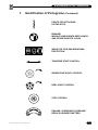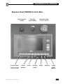
1
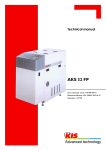
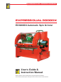
EXPRESSANGLEMASTER
DUAL 3000DX MANUAL
AM1000
EXPRESS DUAL 3000DX
ED3000DX Automatic Spin Grinder
User ’s Guide &
Instruction Manual
Please read this manual carefully before using the Express Dual 3000DX.
This
manual should
© Bernhard and Company Limited
• AM1000/0902
be kept in a safe place so that it can be used for future reference.
1
EXPRESS DUAL 3000DX
EXPRESS DUAL
ED3000DX Precison Reel/Cylinder Grinder
You are now the owner/operator of a Bernhard’s Express Dual 3000DX which, if
cared for and operated correctly, will give you years of good service.
This manual will enable you to obtain the best results from your Express Dual so
please read it thoroughly before using your machine.
If you have any service or operational problems contact your distributor,
or phone our
Technical Helpline (USA only) – 1-888 474 6348
or
Bernhard and Company Ltd, England – (+44) 1788 811600
or email
[email protected]
use the technical support feedback form on our web site
www.expressdual.com or www.bernhard.co.uk
Contents
Identification of Pictograms
2
Safety
5
Installation
6
Identification of Tools and Equipment
8
Understanding the Machine
9
In Frame Grinding
11
Electrical Fault Finding
21
Maintenance
22
Part Lists and Exploded Diagrams
26
Quick Start Guide
43
BERNHARD AND COMPANY LTD
Bilton Road • Rugby • England • CV22 7DT
Tel +44 1788 811600 • Fax +44 1788 812640
Email: [email protected]
© Bernhard and Company Limited • ED3000DX S 03/03
ED3000DX S 03/03
USA Toll Free 1-888 GRIND IT (1-888 474 6348)
1
EXPRESS DUAL 3000DX
1.
Identification of Pictograms
MAXIMUM LIFT PLATFORM
LOAD - 250 KG (550 LBS)
BEWARE!
TRAPPING FEET OR OTHER OBJECTS
WHEN LOWERING LIFT PLATFORM
BEWARE! HIGH VOLTAGE
MAXIMUM GRINDSTONE
DIAMETER 150mm
MAXIMUM SPEED 4000 Rev/Min
RUNS AT 2200 Rev/Min
BEWARE!
MOVING GRINDSTONE AND SHAFT
REEL ROTATING AT BETWEEN
147 AND 255 Rev/Min
TOTAL WEIGHT OF MACHINE (KG)
© Bernhard and Company Limited • ED3000DX S 03/03
2
EXPRESS DUAL 3000DX
1.
Identification of Pictograms (Continued)
POINTS FOR ATTACHING
LIFTING EYES
BEWARE!
MOVING COMPONENTS KEEP HANDS
AND OTHER OBJECTS CLEAR
WEAR EYE, EAR AND BREATHING
PROTECTION
TRAVERSE START CONTROL
GRINDSTONE START CONTROL
REEL START CONTROL
STOP CONTROL
ENGAGE / DISENGAGE (INCREASE /
REDUCE) GRINDSTONE FEED
© Bernhard and Company Limited • ED3000DX S 03/03
3
EXPRESS DUAL 3000DX
Express Dual 3000DX Control Box
Control System
On/Off
Function Keys
(Screen prompts
which to press)
© Bernhard and Company Limited • ED3000DX S 03/03
Pause/
Resume
Reel Spin
Speed Adjust
Finish
Vacuum
On/Off
Emergency Stop
(Twist to release)
Clamp
Unclamp
Toggle
Auto/
Manual
4
EXPRESS DUAL 3000DX
2.
Safety
2.1
This machine is designed and manufactured ONLY for grinding lawn mower reels, rollers,
groomers and verticut units, and MUST NOT be used for any other purpose.
2.2
This machine should be installed, operated and maintained by competent personnel who
have received adequate training.
2.3
Before carrying out any work on the machine, other than grinding, ALWAYS SWITCH OFF
the main electrical supply, or remove the power lead from its socket.
2.4
ALWAYS operate the machine with the guards in position.
2.5
NOISE - Owing to the widely varying conditions of use, noise emissions may vary
considerably. There may be occasions when the safe noise level may be exceeded (see
note on noise emission). In this case adequate ear protection MUST be worn.
2.6
NEVER fit or use a grinding wheel (or other spares) other than those supplied specifically
for use on the EXPRESS DUAL (Warranty will be invalidated).
2.7
NEVER fit or use a grinding wheel which has been dropped or subjected to any other form
of abuse.
NOTE: Grinding wheels should be fitted ONLY by competent, trained personnel.
2.8
NEVER leave rags or tools on the machine or wear any loose clothing or other articles
which could be caught in moving components.
2.9
NEVER allow any combustible materials to be placed on or around the machine.
2.10
ALWAYS ensure that all parts of the cutting unit being ground are securely fixed.
2.11
ALWAYS ensure that all electrical connections are sound and all cables are safely routed.
2.12
ALWAYS carry out cleaning and maintenance of the machine as instructed in this manual
(Refer to safety note 1.3).
2.13
STAY ALERT. Watch what you are doing. NEVER operate the machine when tired, or
under the influence of drugs or alcohol.
If a lift table is fitted NEVER attempt to lift in excess of the rated capacity, and always
ensure that the area is clear before lowering the load.
© Bernhard and Company Limited • ED3000DX S 03/03
5
EXPRESS DUAL 3000DX
3.
Set Up and Installation
3.1
Handling
If the machine is crated, it can be moved by a suitable fork lift truck or pallet truck under
the pallet (skid). Once the lid and sides of the crate are removed, a fork lift truck may be
used under the lifting members of the machine chassis.
The machine can be lifted off the pallet using suitable lifting tackle through 4 lifting eyes
(provided) fitted at the points indicated on the top corners of the machine.
The total weight of the machine is indicated on the machine plate and also at the front of
this manual.
3.2
Location
The machine should be located in a well lit environment with adequate headroom. For
ideal operation, the machine should be accessible from the front, rear and at least one
side, with clearance around it as indicated in the sketch (Fig. 3.2).
���� �� ���
����� �� �������
���� �� ���
������ �������� ����� ���
������� ����� ��� ��� � ����
����� ��� �������
Fig: 3.2
3.3
Leveling
The machines should, ideally, be placed on a solid level floor, and this should be
checked by placing a spirit level on the table. Check the level in both directions. Steel
shims should be placed under the feet as necessary to ensure that the machine is firm and
level. Bolt holes are provided in the feet which can be used for fixing down if required.
NOTE Ensure that the packing under the feet is correct before tightening the bolts, otherwise
twisting of the frame may occur.
© Bernhard and Company Limited • ED3000DX S 03/03
6
EXPRESS DUAL 3000DX
3.
Installation (Continued)
3.4
Electrical Supply
USE A QUALIFIED ELECTRICIAN
The EXPRESS DUAL is supplied with a .55 kW (3⁄4 HP) single phase main (grind) motor
plus 2 fractional HP motors, for spin and traverse.
Power connection to the machine is via plug and socket termination of the lead supplied.
Connection is at the rear of the main electrical control box on the right hand end of the
machine.
Ensure that any cable or conduit run to the machine does not constitute a hazard to the
operator or other personnel.
Machine should be connected to the supply via a 20A breaker.
The top of the reel and the top of the grinding wheel should both move away from the
front of the machine (i.e. both rotate clockwise when viewed from right hand end of the
machine). In this way, the reel and grinding wheel are moving in OPPOSITE DIRECTIONS
at the point of contact.
3.5
Preparation
If the machine has been
received in a crate, the handles
on the control wheels should be
removed from the underneath of
the control wheels and refitted to
the top (see Fig. 3.5).
It is important that the protective
film on the main shaft is
removed prior to using the
machine. This can be done
using a WD40 or similar product
(not gas/petrol) and then drying
the shaft with a clean, dry cloth
so that the grinding wheel
assembly moves freely along the
whole length of the shaft.
Fig: 3.5
A spray lubricant, such as WD40, should be applied to all bare metal surfaces and moving
parts; this includes the reversing bar and the shafts (along which the fork assembly
traverse, but NOT THE MAINSHAFT).
The mainshaft should be washed down as instructed in the maintenance section of this
manual. The feed control screws are normally coated with molycote, and may be washed
down with WD40 if required and recoated with molycote (or similar anti friction coating)
when dry.
© Bernhard and Company Limited • ED3000DX S 03/03
7
EXPRESS DUAL 3000DX
4.
Indentification of Tools and Equipment
The items below may not necessarily be included since the tools and equipment
supplied will vary according to the machine specification.
4.1
Express Dual 3000 and 3000DX (see illustrated parts list).
A4066 Long 1/2” AF Ball handled Allen Key
A2706 3/16” AF Tee handled Allen Key
A2719
Grinding Wheel Nut Wrench
A2720 1/2” AF Allen Key
A2714
Adjustable Sprocket Driver
A9182
Drive Rod Plain (short)
A4134
Drive Rod Square (short)
A4063 2 Pin Drive (large)
A4276
2 Pin Drive (small)
A9181
3 Pin Drive (small)
A4097 Adjustable Plain Shaft Driver
A2712
8mm Long Series Allen Key
A6161
1/8” Allen Key
A4087 Channels for Multifix Brackets
A6342 Backing up/Pressure Plate (not shown)
A4106
Ransomes 5/7 Driver (Standard only on European units)
A6737
Diamond Dresser
A9500 Adustable Front Roller / Multifix Brackets
© Bernhard and Company Limited • ED3000DX S 03/03
8
EXPRESS DUAL 3000DX
5.
Understanding the Machine
5.1
General Principles
The EXPRESS DUAL is designed to grind reels completely assembled, or as a separate
“loose” reel. A Loose Reel Kit (Available as an optional extra, at additional cost) is required
for this operation.
The basic principle of the EXPRESS DUAL is to grind mowers in exactly the same
conditions that they mow in. The grinding wheel takes the place of the grass, striking the
reel in relatively close proximity to that found in the mowing position.
5.2
Basic Requirements
It is important that grinding the cutting unit, when it remains completely assembled, takes
place under the following conditions:
5.2.1
The reel bearings MUST be in good condition, adjusted correctly and if the roller is to be
located on the roller mounting brackets or the multifix brackets, the roller bearings MUST
also be in good condition.
5.2.2
The bedknife must be ground separately on a machine, such as the ANGLEMASTER
bedknife grinder which can guarantee that the blade will be perfectly STRAIGHT and flat
whilst mounted on the bedbar.
During the reel grinding process, it is advisable that the bedknife/bedbar assembly is
replaced in the unit after having been ground. On many units the bedknife/bedbar is an
integral part of the frame and contributes to its strength and rigidity.
5.2.3
The reel or bedknife must be adjusted away from one another to allow free rotation (There
should be no reel to bedknife contact!).
5.2.4
It is essential that all work to be carried out on the mowing unit (all mower repairs
– bearings, seals, roller work, etc.) has been completed prior to grinding the reel. The last
operation of all, apart from final setting reel to bedknife, is the actual grinding of the reel
in-frame.
It is essential that the unit is held totally firm during the grinding process. When in frame
grinding, the front of the unit must be held firmly in the multifix brackets or on the front
roller brackets.
5.2.5
It is essential that the unit is held totally firm during the grinding process. When in frame
grinding, the front of the unit must be held firmly in the multifix brackets or on the front
roller brackets.
The rear of the unit will be held by the radiused pressure bar at the rear of the grinder.
© Bernhard and Company Limited • ED3000DX S 03/03
9
EXPRESS DUAL 3000DX
5.
Understanding the Machine (Continued)
5.3
Machine Functions
The EXPRESS DUAL has 3 separate motors driving the different functions of the machine,
all are controlled from the control panel. These functions are as follows:
5.3.1
Traverse
This motor and the accompanying drive mechanism controls the automatic movement of
the grinding wheel along the mainshaft.
5.3.2
Reel/Spin drive
This motor drives the reel through a flexible shaft driving from a drive mechanism under
the table. It is a three phase motor controlled by an inverter for varying output speed.
5.3.3
Grinding Wheel
A motor situated under the table, drives the mainshaft and grinding wheel at 2200 rpm.
5.3.4
Stop
Pressing the stop button shuts off all 3 motors and locks into the “off” position. None of
the start buttons will operate until the stop button has been unlocked by twisting the knob
counter-clockwise to release it.
NOTE The machine must NOT be stopped when there is contact between the reel and grinding
wheel, except in cases of emergency.
5.3.5
Reset Button (see also Electrical Fault Finding section)
If the main motor is subject to a voltage drop or overloading, the current being drawn will
rise and a safety device will automatically shut the grinder off. The overload trip switch is
situated behind the blue reset button on the cover of the main electrical control box which
is located on the right hand end of the machine.(looking from the front).
The trip setting will vary with the electrical specification of each machine and is normally
set to the full load current of the motor. If the overload trip has shut off the grinder it can be
reset by pushing the reset button after a few minutes delay. This will allow the grinder to be
re started.
NOTE The reset button and overload are both variable and should be adjusted, if required, as
indicated in the appropriate service bulletins.
The reel drive motor, traverse motor, and VSD inverter (reel spin speed control) are
protected by individual fuses located in the electrical control box and accessible without
the necessity of opening the box.
© Bernhard and Company Limited • ED3000DX S 03/03
10
EXPRESS DUAL 3000DX
6.
In-frame Grinding
6.1.1
Mower Preparation
Units of up to 36” long can be ground
in frame, this includes most machines
including Greens mowers and Fairway
units. In order to spin / drive the reel,
one end of the reel shaft drive must be
exposed. This will require the removal
of the hydraulic motor, the chain / belt
or cover depending on which type
of unit is being ground. This should
be done before the mower is on the
grinder (see example Fig. 6.1).
Ensure that the mower is clean and
that both reel and roller bearings are
in good condition. Also ensure that
the bedknife has been sharpened, if
necessary, and replaced with a small
amount of clearance between it and the reel.
Fig: 6.1
FOLLOW THE ILLUSTRATED INSTRUCTIONS IN THE QUICK START
GUIDE AT THE END OF THIS MANUAL
6.1.2
Press F1 button to progress from the welcome screen
FOLLOW THE SCREEN PROMPTS
6.1.3
Press F1 button to select automatic mode – display advances to next screen
6.1.4
Screen prompts to:
Ensure traverse is not engaged
To mount mower
To engage clamp
6.1.5
Unscrew the traverse engagement screw until it is released from the traverse chain so that
fork/grindstone can be traversed manually along the mainshaft.
© Bernhard and Company Limited • ED3000DX S 03/03
11
EXPRESS DUAL 3000DX
6.
In-frame Grinding (Continued)
6.2.
Mounting Mower
The mainshaft / Grinding stone should be wound down to its lowest position and the unit
placed on the table. The unit should then be carefully moved towards the multifix brackets
or front roller brackets, which can be adjusted in any direction to allow the unit to be fixed
in such a position that the grinding wheel can be raised towards the reel without coming
into contact with either the bedknife or the front roller/groomer.
6.3.
Clamping
With the mower correctly positioned the radiused pressure bar) is moved forward to rest
on the rear of the mower and locked in position by pressing the F8 key on the operator
display panel (F9 undoes the clamp) on the operator control panel downwards. The
operator should release the key as the pressure bar engages the cutting unit thus retaining
pressure on the mower until the grinding operation is completed. A backing up plate is
supplied to protect the rear of the units and to evenly disperse the force of the pressure bar
across the width of the mower (see Fig. 6.3.1.)
Fig: 6.3.1
© Bernhard and Company Limited • ED3000DX S 03/03
12
EXPRESS DUAL 3000DX
6.
In-frame Grinding (Continued)
To ensure that the correct position for the mower unit has been achieved, both control
wheels (right hand and left hand) should be wound in a clockwise direction so that the
grinding wheel may be placed to contact each end of the reel evenly. If the grinding wheel
touches the bedknife or any part other than the reel, the whole unit must be moved by
adjusting the position of the multifix brackets or roller brackets. The exact position required
will be easily seen by looking along the mainshaft from one end of the machine as the
stone is raised to check that the point of contact is in a suitable position (see Figure 6.3.2).
Front Roller position
is adjustable
Reel
blades
Grind stone has to contact
reel blades for sharpening
without touching anything else
Position of
bedknife is
adjustable
Fig: 6.3.2
Adjustable Front
Roller support
NOTE If the cutting unit has no front roller fitted so that the multifix brackets are used then, once
the correct position for any particular unit has been finalised a “set up guide” should be
completed and filed for future reference so that the identical multifix brackets positions can
be used for all subsequent applications on the same type of unit.
© Bernhard and Company Limited • ED3000DX S 03/03
13
EXPRESS DUAL 3000DX
6.
In-frame Grinding (Continued)
6.4
Linking Up The Reel Drive Unit to the Reel
Machines are supplied with the reel drive motor under the table and a flexible drive which
can be attached to either end of the machine do not have to be prepared before the mower
unit is placed on the table, as the complete drive unit can be moved to either side of the
table with a mower unit in place.
6.4.1
Select the attachment with which to drive the reel. If the reel sprocket, gear or pulley
is secured with a nut it may be easier to use a standard socket together with a 1/2”
square end driver. Ensure the nut is tight as the direction of rotation may tend to unscrew
it. Ensure that the drive shaft is through the flexible coupling/driver before setting the
machine on the table and that the whole unit is at the correct end of the table.
Alternatively it may be easier to drive directly onto the sprocket using one of the pin or
adjustable type sprocket drivers fitted to the plain drive rod.
6.4.2. When the cutting unit is in place and firmly fixed into the multifix brackets, or front roller
brackets, and the rear clamped with the radiused pressure bar, adjust the drive unit left or
right so that the appropriate drive rod will reach the end of the reel shaft. Tighten unit in
place.
Adjust the height and position, forwards and backwards and up and down, of the cable
drive drive support so that the shaft is square with the driven end of the reel, and tighten
clamps to hold it in place.
The black lobed hand screw allows the drive head to be moved along the square support
shaft to adjust the height of the drive, while the 5/8” hex headed socket screw allows the
support shaft to be clamped at any desired angle, and also allows the whole assembly to
be moved left or right along the machine bed to engage in the drive mechanism on the
reel.
The drive head of the shaft can also be slid through it’s support for further adjustment or
final connection/ disconnection of drive.
6.4.3
Tighten the drive rod via the allen screw in the flexible coupling onto the flat of the drive
shaft.
© Bernhard and Company Limited • ED3000DX S 03/03
14
EXPRESS DUAL 3000DX
6.
In-frame Grinding (Continued)
6.4.4
Moving the flexible Shaft
There is a layshaft socket at both ends of the
machine into which the flexible drive can be
engaged as required. The other end of the
flexible shaft can be disconnected if required
but this would not generally be necessary as the
bracket and shaft would normally be moved as
an assembly.
The flexible drive shaft can be detached
from its socket on the end of the machine by
pulling sharply on the shaft, to release it from
a spring loaded ball detent. (Earlier units by
first removing the spring retainer (R-pin)), and
withdrawing the complete shaft. When replacing
the shaft, ensure that it is properly engaged
in the layshaft socket (and if appropriate, the
spring retainer securely replaced).
By loosening the socket screw and allowing
the clamp nut, under the table, to twist through
approximately 90 degrees, the whole assembly
can be lifted clear of the table, and moved to the
other side of the mower unit if required.
Press F1 key on operator display – display advances to next screen.
© Bernhard and Company Limited • ED3000DX S 03/03
15
EXPRESS DUAL 3000DX
6.
In-frame Grinding (Continued)
6.5
Actual Grinding
Screen requests size of mower.
6.5.1
Press the relevant ‘F’ key to select size of mower:
(F1=Small, F2=medium or F3=large)
Display advances to the next screen.
Screen requests type of grind required.
6.5.2
Press the relevant ‘F’ key to select type of grind required:
• F1 = ”touch up” (mower needs little sharpening, probably part of a regular sharpening
regime)
• F2 = ”maintain” (blades need just a little more material removing to get a good edge) or
• F3 = ”rectify” (damaged blades, or a unit rarely ground or heavily back-lapped)
Display advances to the next screen.
6.5.3
Screen shows selected answers (grind cycle) – Press F1 key if OK
CLOSE GUARD FIRST – display advances to the next screen
or press F2 if you wish to make an alternative selectionDisplay returns to size of mower question.
When F1 is pressed the Grind, Traverse and Reel drive motors start in turn.
Display advances to the next screen.
© Bernhard and Company Limited • ED3000DX S 03/03
16
EXPRESS DUAL 3000DX
6.
In-frame Grinding (Continued)
6.5.4
Set up of Traverse
With motors running, the screen prompts:
“set grind stone to reel” and
“set traverse limit stops”
Traverse the grinding wheel by hand, using the Traverse Engagement Screw until it is at
the extreme point of desired travel. Ensure that the traverse reversing bar is also moved in
that direction and slide the reversing stop up to the grinding wheel traverse assembly and
tighten. Move the grinding wheel to the opposite end of the desired travel and repeat the
operation ensuring that the reversing bar has also been moved in the opposite direction.
This is critical where the grinding wheel cannot pass beyond the end plates if they protrude
below the maximum diameter of the reel.
NOTE On the EXPRESS DUAL it is not necessary for the whole width of the grinding wheel to
pass the end of the reel and it SHOULD NOT DO SO EVEN IF SPACE PERMITS (see
Fig. 6.5.4).
Ensure that the leading edge
of grinding stone passes the
end of the reel – but clearance
must be maintained between
stone and end frame of unit.
Fig: 6.5.4
NOTE: The reversing bar will move approximately 1⁄2” (13mm) before the direction of travel is
reversed and will allow the grinding wheel to move with it. It is therefore ESSENTIAL that
this is taken into account when setting the maximum point of travel.
© Bernhard and Company Limited • ED3000DX S 03/03
17
EXPRESS DUAL 3000DX
6.
In-frame Grinding (Continued)
6.6.1
With the stone positioned at the left hand end of the reel, place the left hand on the left
hand control wheel and the right hand on the traverse knob, moving the grinding wheel
along the reel by hand using the traverse engagement screw, wind up the left hand control
wheel clockwise until the grinding wheel strikes and sparks gently against the reel.
6.6.2
Unwind a complete turn to move the stone away from the reel.
6.6.3
Move the grinding wheel to the right hand end of the reel and, using the right hand on the
right control wheel, raise the shaft until the reel again can be gently rotates against the top
of the grinding wheel.
6.6.4
Unwind half a turn.
6.6.5
Go back to the left hand end and repeat the process but this time, after contact has been
made, unwind only sufficiently to release the contact.
6.6.6
Go back to the right hand end and repeat the process and again release the contact only
slightly.
6.6.7
Repeat this process on the right hand side of the reel, raising the shaft with your right hand
and moving the grinding wheel along with your left hand. Repeat this process until the
contact all along the reel is light, even and parallel.
6.6.8
Screw in traverse knob to engage power traverse.
NOTE: Check auto traverse is changing direction at correct point at each end of its
movement.
6.6.9
Press F1 key to start grinding cycle
Screen reads “GRINDING”
Both handwheels will automatically rotate clockwise to apply a parallel cut to the reel.
After a pre-determined number of traverse passes of the ‘stone along the reel a further
infeed will be applied.
According to the program selected a certain number of infeeds / traverse passes will follow
until the cycle is completed. Both handwheels will then rotate counter- clockwise, to back
the ‘stone away from the reel, and all motors will stop.
Screen reads “PROGRAM COMPLETE
(Programme will NOT let a reel “spark-out”)
© Bernhard and Company Limited • ED3000DX S 03/03
18
EXPRESS DUAL 3000DX
6.
In-frame Grinding (Continued)
6.6.10 Press F1 key if reel is satisfactory
or
Press F2 key (“re-do”) if it needs more grinding, to repeat the whole cycle
or
Press F3 key if reel is almost there but could do with a “touch up” to finish it off.
6.6.11 Pressing F1 – display advances to the next screen “Grinding completed – remove
mower from machine”.
6.6.12 Press F9 key to undo clamp and remove mower.
6.6.13 Press F1 “next mower” key to return to the starting screen.
6.7
ALTERNATIVES
6.7.1
If “re-do” or “touch up are selected, (close the guard before selection).
After a pause the motors will re-start and the handwheels will return the grindstone to the
position where the grind cycle finished. Further feeds/traverse s will follow until the cycle is
completed once more,
or
6.7.2
The F4 “PAUSE” key is pressed.
If F4 is pressed during a grind cycle the ‘stone will be backed away from the reel and the
motors will be stopped. Display screen will read:
“PAUSED” “Press F4 to resume, F5 to End”
6.7.3
At this time the guard can be opened and the condition of the reel checked.
6.7.4
If the blades are sharp enough the “F5 Key” can be pressed. The display will change to
“Grinding completed – remove mower from machine” screen.
or
6.7.5
If the blades still need some grinding, the “F4-resume, key” can be pressed, after
closing the guard. After a pause the motors will re-start and the handwheels will return the
grindstone to the position where the grind cycle was paused. The cycle will continue to it’s
conclusion.
© Bernhard and Company Limited • ED3000DX S 03/03
19
EXPRESS DUAL 3000DX
6.
In-frame Grinding (Continued)
6.8
MANUAL MODE GRINDING
If at screen #2 “F2 – Manual Mode” is selected, the Express Dual can be used as with
any other machine in the ED series.
The operator display shows the three motor buttons as:
• F1 – Grind
• F2 – Traverse
• F3 – Spin (reel)
In manual mode, pressing one of these F – keys once will start a motor, pressing it a
second time will then stop the motor.
Also displayed are two digital, numerical counters, one for each handwheel. Pressing the
F4 – Reset key will set these counters to zero.
The clamp is still operated by the F8 and F9 keys and the vacuum can be “toggled” on
and off using the F7 key
For other screen information see QUICK START GUIDE at the back of this manual.
© Bernhard and Company Limited • ED3000DX S 03/03
20
EXPRESS DUAL 3000DX
7.
Electrical Fault Finding
USE A QUALIFIED ELECTRICIAN
In the event of any motor not starting, the following procedure should be adopted:
7.1.
Check that STOP BUTTON in control panel on top of machine is not permanently in STOP
position.
7.2
Check fuses – main fuses feeding machine and small fuses in junction box for traverse
and reel motors.
7.3.
Check that reset button on junction box is not making contact with red button on the
overload. If it is adjust RESET so that it CLEARS THE BUTTON, this must be tested with
lid held in position on box.
7.4.
Check voltage in electrical box, right hand side of machine – terminal block, terminals 1 and 4.
7.5.
Check for open circuit on overload, terminals 95 and 96, to determine whether or not main
motor is faulty. If open press red resetting button on overload.
7.6.
To determine that all three contactors are OK test each one by pushing start button on
the individual contactors, they should noticeably pull in. This can be checked by someone
looking in the junction box while the start buttons are pressed.
7.7.
Traverse
If the contactor is functioning properly check the microswitch. If this is found to be OK
check capacitor if possible. If neither of these is faulty, then the motor is probably at fault.
7.8.
Reel Drive
If the contactor is functioning properly, check the Inverter:
There is a small LED lamp on the front of the unit. This should be green. If it is red, or
changes to red when pressing the start button, there is an inverter fault.
Disconnect the power to the machine, wait 2 minutes, then re-connect and try again (to
re-set the inverter). If the LED is still red the inverter may have failed.
If neither are faulty then the motor is probably at fault.
7.9.
Main Motor
If the contactor is functioning correctly, check the load current with an ammeter across
terminals 2 and 3 on 12 way terminal block. If this exceeds full load current indicated on
the motor identification plate then a new motor is needed. If the reading is below full load
current then possibly the overload is set too low.
NOTE Before assuming that there is an electrical fault in any of the systems ensure that the
mechanical drive assemblies attached to a particular motor are moving freely, and have
not got increased resistance due to damage, or the build up of dirt. This can best be done
by detaching the motor drive and ensuring that the mechanism is moving freely.
© Bernhard and Company Limited • ED3000DX S 03/03
21
EXPRESS DUAL 3000DX
8.
Maintenance
8.1
Grinding Wheel Replacement
NOTE Grinding wheels should always be fitted by competent, trained personnel.
8.1.1
The grinding wheel (stone) is held on the carrier by a nut which should be loosened, using
the “C” Spanner provided, before the assembly is removed from the mainshaft.
8.1.2
Slide the grinding wheel to the left hand side of the machine (viewed from the operator
position).
8.1.3
Release the 2 allen screws in the bearing flange ring on the left hand end of the main
shaft.
8.1.4
Raise the mainshaft to its maximum height, maintaining the shaft as horizontal as possible
until the right hand side comes up against the stop in the feed column and the left hand
side is at its maximum height. At this point the fork will drop away from the grinding wheel
assembly.
Fig: 8.1.5
8.1.5
Place a wooden block under the mainshaft to the right hand side of the grinding wheel
assembly, bridging the front bed and front channel to take the weight of the mainshaft
when the side arm is removed (see Fig. 8.1.5).
© Bernhard and Company Limited • ED3000DX S 03/03
22
EXPRESS DUAL 3000DX
8.
Maintenance (Continued)
8.1.6
USING THE “C” SPANNER PROVIDED, loosen the retaining nut.
8.1.7
Remove the circlip retaining the left hand side arm to the rear shaft. The side arm can now
be removed from the machine.
8.1.8
The grinding wheel and sleeve can now be withdrawn. Remove the retaining nut and the
old wheel. Clean sleeve and nut thoroughly.
8.1.9
Fit the new grinding wheel and replace the collar, ensuring that all mating services are
clean and undamaged.
8.1.10 Ensure that the mainshaft and sleeve are perfectly clean and dry. Reassemble in the
reverse order ensuring that when you replace the grinding wheel assembly onto the
mainshaft, the nut is on the LEFT HAND side when viewed from the operator’s position
(Tighten nut whilst assembly is on the mainshaft).
NOTE Be careful to guide the assembly into the fork when lowering the mainshaft. Make sure that
the left hand side arm is centered in the channel.
8.1.12 Loosen the small allen key in the reel drive support block, pull the diamond dresser out a
short way and re tighten the screw.
8.1.13 With the stone NOT running, bring the mainshaft (and grindstone) up horizontally.
Manually traverse the ‘stone past the diamond, making a light scratch, to confirm that the
shaft is horizontal.
8.1.14 Move the stone just clear of the dresser then start the grind motor.
8.1.15 Bring up the shaft equally on each side and manually traverse the ‘stone across the
dresser.
8.1.16 Switch on and engage the auto traverse with the stops set so that the stone completely
passes the dresser back and forth.
8.1.17 Apply more feed as necessary to true the stone.
NOTE Dressing in this way should be carried out periodically to keep the grindstone clean and
true BUT remove only the minimum material off the stone to keep long service.
© Bernhard and Company Limited • ED3000DX S 03/03
23
EXPRESS DUAL 3000DX
8.
Maintenance (Continued)
NOTE When fitting a new sleeve and nut, it may appear that the assembly is too tight to fit onto
the mainshaft of the Express Dual.
This is because all replacement sleeve and nut assemblies are shipped with the drive key
left very slightly oversize to allow for varying degrees of wear in the mainshaft keyway.
(The key is “peened” (like riveting) into the sleeve NOT welded).
The key needs to be “fitted” to the mainshaft. This may entail filing a small amount of
material from both the depth of the key and the sides. Remove only a very small amount of
material at a time, then check the fit, until the sleeve and nut assembly slides freely along
the length of the mainshaft without any play between key and keyway.
REMEMBER
The mainshaft keyway will be less worn at the ends of the shaft than where the normal
traverse of the grindstone occurs, do not remove too much metal from the key.
NEVER grip the sleeve and nut assembly in a vice. Fully tighten the nut when the
assembly is fitted to the mainshaft.
Key
Sleeve
Mainshaft
2nd Key
© Bernhard and Company Limited • ED3000DX S 03/03
Remove minimal material from
sides and bottom of key
24
EXPRESS DUAL 3000DX
8.
Maintenance (Continued)
8.2
Lubrication
8.2.1
Daily
Mainshaft – Wipe off any deposits of grinding dust with a dry cloth or brush ensuring the
keyways are kept clean. Using a fine spray oil, such as WD40, spray the whole shaft. Use
an excess of WD40 in one place and slide the grinding wheel assembly backwards and
forwards over that area in order to wash out thoroughly the inside of the sleeve. This will
remove any build up of material and ensure the free movement of the assembly along the
shaft.
After thoroughly cleaning the shaft, dry and ensure that no oil remains at all.
It is essential that the grinding wheel sleeve and nut can be moved freely along the entire
length of the mainshaft at all times.
Occasionally lubricate the contacct areas of the fork driver (with the sleeve and nut) with
“MOLYCOTE” (Molydbenum Disulphide), this will impregnate the surface. Excess lubricant
/ propellant should be wiped off again after a short time.
NOTE Never apply nor leave any oil or grease on the mainshaft.
8.2.2
Weekly
Spray WD40 or equivalent onto all moving parts (the mainshaft must be completely dried
before any grinding is carried out). This includes the threads under the feed column
handwheels, the reversing bar and the shafts on which the fork and pickup assembly run.
The majority of bearings are either oil impregnated or are ball races and, apart from those
mounted in special sealed housings or fitted with grease nipples, require the occasional
drop of oil. These include the reel drive coupling bearings and the pressure lever pivot
bearings.
8.2.3
6 Monthly
Chain and idler sprocket require cleaning and oiling.
Examine belts for wear and tension. DO NOT OVER-TIGHTEN. Examine fork assembly
for wear – some slight discolouration may occur, this is not a problem.
8.2.4
Yearly
Mainshaft bearings are pre-packed with grease. IF grease nipples are fitted ONLY 1
SMALL SHOT of grease should be applied annualy.
These bearings run warm/hot, that IS OK. Extra grease will not reduce the temperature,
more likely the reverse, the seals and subsequently the bearings may fail prematurely.
© Bernhard and Company Limited • ED3000DX S 03/03
25
EXPRESS DUAL 3000DX
9.
Parts List
Page
MAIN FRAME ___________________________________________ 27
FEED ADJUSTMENT _____________________________________ 28
MAINSHAFT MOUNTING AND MAIN MOTOR DRIVE _________ 30
TRAVERSE ASSEMBLY __________________________________ 32
REEL DRIVE ____________________________________________ 34
CLAMP ASSEMBLY ______________________________________ 36
MULTI-FIX BRACKET ASSEMBLY _________________________ 37
GUARD ________________________________________________ 39
CONTROL BOX _________________________________________ 41
ELECTRICAL CABINET __________________________________ 42
© Bernhard and Company Limited • ED3000DX S 03/03
26
EXPRESS DUAL 3000DX
9.
Parts List (Continued)
Ref #
Name of Part
Qty.
Part #
MAIN FRAME _______________________________________________________________
1
Frame ...................................................................................... 1
A4050
2
Top Plate ................................................................................. 1
A4142
3
Upper Front Skirt ..................................................................... 1
A6352
4
Rear Skirt ................................................................................ 1
A6397
(not required if Lift Table fitted)
5
Front Skirt................................................................................ 1
A6328
6
Drawer ..................................................................................... 2
A6321
7
Drawer Handle ........................................................................ 2
A6110
8
Dust Tray ................................................................................. 1
A6323
9
Dust Tray Handle..................................................................... 2
A6111
10
Drawer Runner (Pad) .............................................................. 4
A6742
11
Drawer Runner (Drawer) ......................................................... 4
A6741
12
M5 x 10 Button Socket Screw ................................................. 8
A5129
�
��
�
�
�
�
�
�
�
��
�
��
© Bernhard and Company Limited • ED3000DX S 03/03
27
EXPRESS DUAL 3000DX
9.
Parts List (Continued)
Ref #
Name of Part
Qty.
Part #
FEED ADJUSTMENT _________________________________________
1
Feed Channel L.H. c/w top & bottom cap............................... 1
A4041
Feed Channel R.H. c/w top & bottom cap .............................. 1
A4042
2
Feedscrew Cap c/w Bush ....................................................... 4
A4044
3
Feedscrew ............................................................................... 2
A9039
4
Locknut .................................................................................... 4
A5502
5
Handwheel 150mm dia ........................................................... 2
A6113
6
5/8” Double Coil Spring Washer ............................................. 2
A5303
7
5/8” whit x 5/8” Socket Screw ................................................. 2
A5110
8
5/8” Washer............................................................................. 4
A5305
9
Bush (included with item 2) ..................................................... 4
10
Feed Nut.................................................................................. 2
A4043
11
Spring Coupling Kit ................................................................. 2
A9700
12
Encoder ................................................................................... 2
A8074
13
Saddle Clamp.......................................................................... 2
A6851
14
M5 x 10 Button Head Screw ................................................... 4
A5129
15
M5 Washer .............................................................................. 4
A5318
16
Cross Helical Gearbox 1:3 ...................................................... 2
A6007
17
Feed Layshaft......................................................................... 2
A9069
18
Electromagnetic Clutch 24v .................................................... 2
A8057
19
Feed Motor 24v ....................................................................... 2
A6018
Alternative Encoder Mounting
12
Encoder ................................................................................... 2
A8074
17A
Feed Layshaft for ......................................................................
A9069
20
Encoder Layshaft Coupling..................................................... 2
A9284
21
Encoder Support Stud............................................................. 2
A9285
N.B.
Item 6 is replaced by a die spring of known compression from machine no. 13392.
© Bernhard and Company Limited • ED3000DX S 03/03
28
EXPRESS DUAL 3000DX
9.
Parts List (Continued)
�
�
�
�
�
�
�
�
�
��
��
��
��
��
��
��
�� ���
��
FEED ADJUSTMENT
��
��
��
© Bernhard and Company Limited • ED3000DX S 03/03
��
29
EXPRESS DUAL 3000DX
9.
Parts List (Continued)
Ref #
Name of Part
Qty.
Part #
MAINSHAFT MOUNTING AND MAIN MOTOR DRIVE __________________
1
Side Arm L.H........................................................................... 1
2
Side Arm R.H. ......................................................................... 1
A4123
3
Rear Shaft c/w circlips ............................................................ 1
A9108
4
Circlip....................................................................................... 2
A5601
5
Main Motor 220v 60Hz............................................................ 1
A6014
6
A4122
Main Motor 240v 50Hz ............................................................ 1
A6015
Main Motor 3 phase................................................................. 1
A6016
Drive Pulley 60 Hz................................................................... 1
A7202
Drive Pulley 50Hz.................................................................... 1
A7203
7
Taperlock Bush 1108 x 19 ....................................................... 1
A7301
8
Driven Pulley ........................................................................... 1
A7201
9
Taperlock Bush 1610 x 1 1⁄4”.................................................... 1
A7303
10
SPZ Drive Belt 60 Hz .............................................................. 1
A7103
SPZ Drive Belt 50Hz ............................................................... 1
A7102
11
Drive Belt Guard...................................................................... 1
A6334
12
Mainshaft................................................................................. 1
A9068
13
Grinding Stone ........................................................................ 1
A6505
14
Sleeve...................................................................................... 1
A9116
15
Nut ........................................................................................... 1
A9095
Sleeve & Nut assembly ........................................................... 1
A9506
16
Mainshaft Bearing ................................................................... 1
A7721
17
Oilite Bush 1 1⁄4” bore............................................................... 2
A7701
18
Plastic Washer......................................................................... 2
A6759
19
Hex.Nut M12............................................................................ 4
A5506
20
Washer M12 ............................................................................ 8
A5315
21
Hex. Head Bolt M12 x 45......................................................... 4
A5714
22
Hex. Head Bolt M8 x 25 .......................................................... 4
A5216
23
Washer M8 .............................................................................. 4
A5321
24
Motor Bolt Retaining Plate ...................................................... 2
A4078
25
Hex. Set Screw M10 x 70 ........................................................ 2
A5711
26
Locknut M10 ............................................................................ 2
A5503
27
Button Head Socket Screw M5 x 10 ....................................... 2
A5129
28
Limit Switch ............................................................................. 2
A8842
© Bernhard and Company Limited • ED3000DX S 03/03
30
EXPRESS DUAL 3000DX
��
Parts List (Continued)
��
MAINSHAFT MOUNTING
AND MAIN MOTOR DRIVE
��
��
��
��
��
�
��
��
��
�
��
�
��
�
��
�
�
��
��
��
��
�
��
�
�
��
9.
© Bernhard and Company Limited • ED3000DX S 03/03
31
EXPRESS DUAL 3000DX
9.
Parts List (Continued)
Ref #
Name of Part
Qty.
Part #
TRAVERSE ASSEMBLY ___________________________________________________
1
Forkdriver (only) ...................................................................... 1
A9512
Forkdriver c/w bushings & seals ............................................. 1
A9505
2
Shaft for Forkdriver ................................................................. 1
A9050
3
Brackets for Forkdriver Shaft .................................................. 2
A4049
4
Ball Bushing for Forkdriver...................................................... 2
A7706
5
Dust Seals for Forkdriver ........................................................ 2
A7707
6
Button Head Screw M8 x 30 ................................................... 4
A5164
7
Socket Screw M6 x 6............................................................... 2
A5156
8
Shaft for Pick up ...................................................................... 1
A9183
9
Traverse Pick Up ..................................................................... 1
A9518
10
Ball Bushing for Trav. Pick Up ................................................. 2
A7702
11
Dust Seal for Trav. Pick Up ..................................................... 2
A7703
12
Hex. Head Screw M12 x 25..................................................... 2
A5712
13
Washer M12 ............................................................................ 2
A5315
14
Engagement Screw ................................................................. 1
A6112
A6102
15
Lobed Knob M12 ..................................................................... 1
16
Reversing Bar.......................................................................... 1
A4111
17
Reversing Bar Stop ................................................................. 2
A4113
18
Cross Knob M8 x 15................................................................ 2
A6131
19
Microswitch.............................................................................. 1
A8111
20
Housing for Microswitch ......................................................... 1
A8113
21
Guard for Microswitch ............................................................. 1
A6382
22
Screw 2BA x 1 3⁄4”.................................................................... 2
A5404
23
Traverse Motor 60Hz............................................................... 1
A6024
Traverse Motor 50Hz............................................................... 1
A6022
24
Idler Sprocket .......................................................................... 1
A7609
25
Oilite Bush for Sprocket .......................................................... 1
A7704
26
Spindle for Idler Sprocket........................................................ 1
A9057
27
Drive Sprocket......................................................................... 1
A7603
28
Traverse Chain ........................................................................ 1
A7406
29
Link for Traverse Chain ........................................................... 1
A7502
30
Circlip 1⁄2” ................................................................................. 1
A5602
31
Hex. Nut M10........................................................................... 1
A5503
32
Socket Screw .......................................................................... 1
33
Hex Head Screw M6 x 18........................................................ 4
A5719
34
Washer M6 .............................................................................. 4
A5320
35
Capacitor 3uf for Traverse Motor ........................................... 1
A8148
36
Friction Spring for Reversing Bar............................................ 1
A6746
37
Socket Screw 1⁄4”Whit x 1⁄4”...................................................... 1
A5101
© Bernhard and Company Limited • ED3000DX S 03/03
32
EXPRESS DUAL 3000DX
Parts List (Continued)
��
TRAVERSE ASSEMBLY
��
��
��
��
��
�� ��
�� ��
��
��
��
��
�
�
��
��
�
��
�
�� ��
�
��
�
�� ��
��
��
�
�� ��
�
�� ��
�
9.
© Bernhard and Company Limited • ED3000DX S 03/03
33
EXPRESS DUAL 3000DX
9.
Parts List (Continued)
Ref #
Name of Part
Qty.
Part #
REEL DRIVE ________________________________________________________________
1
Reel Drive Motor...................................................................... 1
A6011
2
Layshaft (Long) ....................................................................... 1
A9059
3
Layshaft (Short)....................................................................... 1
A9060
4
Layshaft Bearing ..................................................................... 2
A7722
5
Socket for Flexible Drive ......................................................... 2
A9121
6
Flexible Drive Shaft ................................................................. 1
A7404
7
Flexible Drive Bracket Base .................................................... 1
A4046
8
Retaining Nut........................................................................... 1
A4110
9
‘L’ Post Drive Hd Support Bar ................................................. 1
A4001
10
Flexible Drive Bracket ............................................................. 1
A4045
11
Cylinder Drive Motor Bracket .................................................. 1
A4031
12
Cross Knob M8 x 15................................................................ 2
A6131
13
Ball Spring Plunger ................................................................. 2
A5460
14
Cap Hd Screw 5/8”Whit x 5 1/2” ............................................. 1
A5109
15
Socket Screw M6 x 12............................................................. 1
A5146
16
Diamond Dresser .................................................................... 1
A6737
17
Locknut M10 ............................................................................ 1
A5503
18
Flexible Coupling..................................................................... 1
A6744
19
Grub Screw 3/8” Whit x 3/8” ................................................... 2
A5106
20
Short Square Drive Shaft ........................................................ 1
A4134
© Bernhard and Company Limited • ED3000DX S 03/03
34
EXPRESS DUAL 3000DX
9.
Parts List (Continued)
19
18
10
20
12
14
7
9
15
6
16
8
1
5 13 17
4
2
3
REEL DRIVE
11
4
5
© Bernhard and Company Limited • ED3000DX S 03/03
35
EXPRESS DUAL 3000DX
9.
Parts List (Continued)
Ref #
Name of Part
Qty.
Part #
CLAMP ASSEMBLY ________________________________________________________
1
2
3
4
5
6
7
8
9
10
11
12
Radius Pressure Arm Bracket................................................. 1
Radius Pressure Arm .............................................................. 1
Pressure Bar Rubber............................................................... 2
Linear Actuator ........................................................................ 1
Plug 4 Pin ................................................................................ 1
Hex Head Bolt M16 x 170........................................................ 1
Nyloc Nut M16 ......................................................................... 1
C’s’k Socket Screw M10 x 30 .................................................. 4
Nut M10 ................................................................................... 4
Hex Head Bolt M10 x 45.......................................................... 2
Nyloc Nut M10 ......................................................................... 2
Washer M10 ............................................................................ 6
A4101
A4100
A6761
A6013
A8121
A5749
A5524
A5117
A5503
A5706
A5505
A5310
2
8
3
1
12
6 7
11
9
10
CLAMP ASSEMBLY
4
© Bernhard and Company Limited • ED3000DX S 03/03
5
36
EXPRESS DUAL 3000DX
9.
Parts List (Continued)
Ref #
Name of Part
MULTI-FIX BRACKET ASSEMBLY
Qty.
Part #
_______________________________________
1
Adjustable Mtg Brkt Base L.H................................................. 1
A4012
2
Adjustable Mtg Brkt ‘V’ Base .................................................. 2
A4011
3
Adjustable Mtg Brkt Base R.H. ............................................... 1
A4014
4
‘L’ Upright Mounting Brkt R.H.................................................. 1
A4010
5
‘L’ Upright Mounting Brkt L.H. ................................................. 1
A4009
6
Adjustable Mtg Brkt Horizontal ............................................... 2
A4016
7
Mounting Brkt ‘C’ Clamp L.H. ................................................. 1
A4006
8
Mounting Brkt ‘C’ Clamp R.H.................................................. 1
A4007
9
‘C’ Clamp Screw...................................................................... 2
A4008
10
‘V’ Bracket Clamp Finger ........................................................ 2
A4003
11
Kip Lever M10 x 20.................................................................. 4
A6118
12
‘V’ Bracket Stud M16............................................................... 2
A5401
13
Kip Lever M12 x 30.................................................................. 4
A6121
14
Slide Nut M10 .......................................................................... 2
A4180
15
Nut M16 .................................................................................. 2
A5508
16
Wing Nut M16 .......................................................................... 2
A5509
17
Cap Head Skt Screw M10 x 25 .............................................. 4
A5116
18
Washer M12 ............................................................................ 4
A5315
19
Washer M10 ............................................................................ 4
A5310
20
Base Scale .............................................................................. 2
A6601
21
Button Head Skt Screw M4 x 8 ............................................... 4
A5125
22
Multifix Channel (not shown)................................................... 2
A4087
© Bernhard and Company Limited • ED3000DX S 03/03
37
EXPRESS DUAL 3000DX
��
��
��
�
��
�
�
�
�
�
��
�
�
��
��
��
�
MULTI-FIX BRACKET
ASSEMBLY
��
��
��
��
Parts List (Continued)
��
9.
© Bernhard and Company Limited • ED3000DX S 03/03
38
EXPRESS DUAL 3000DX
9.
Parts List (Continued)
Ref #
Name of Part
GUARD
Qty.
Part #
_____________________________________________________________________
1
Front Guard ............................................................................. 1
A6326
2
Rear Guard.............................................................................. 1
A6345
3
R.H. Side Panel....................................................................... 1
A6431
4
L.H. Side Panel ....................................................................... 1
A6430
5
Frame ...................................................................................... 1
A6429
6
Rear Guard Window................................................................ 1
A6768
7
Front Guard Window ............................................................... 1
A6748
8
Bridge Handle.......................................................................... 3
A6108
9
Hinge ....................................................................................... 4
A6109
10
C’s’k Head Screw M6 x 25 .................................................... 16
A5757
11
Rear Guard Gas Strut ............................................................. 2
A6731
12
Ball Pin for Gas Strut............................................................... 4
A9281
13
Front Guard Gas Strut............................................................. 2
A6747
14
Cap Head Screw M6 x 30 ....................................................... 4
A5153
15
Plastic Rivet........................................................................... 32
A6758
16
Button Head Screw M6 x 10 ................................................... 2
A5142
© Bernhard and Company Limited • ED3000DX S 03/03
39
EXPRESS DUAL 3000DX
9.
Parts List (Continued)
��
�
�
�
�
��
�
��
�
��
�
�
�
GUARD
��
��
��
© Bernhard and Company Limited • ED3000DX S 03/03
40
EXPRESS DUAL 3000DX
9.
Parts List (Continued)
Ref #
Name of Part
Qty.
CONTROL BOX (DX PMU200)
Part #
____________________________________________
1
Control Box + Lid..................................................................... 1
A6439
2
Control Box Arm ...................................................................... 1
A4028
3
On –Off switch (control system).............................................. 1
A8155
4
Comm’s Lead, HMI - PLC........................................................ 1
A8794
5
1k Potentiometer ..................................................................... 1
A8014
6
Emergency Stop Button .......................................................... 1
A8073
7
B4T02 Contact Block (for the above)...................................... 1
A8358
8
PMU 200 Graphical Operator Panel (HMI)........................... 1
A8382
(complete with retaining brackets)
�
�
�
�
�
�
�
�
�
�
�
���� ���� ������ ��� ����
CONTROL BOX
© Bernhard and Company Limited • ED3000DX S 03/03
41
EXPRESS DUAL 3000DX
9.
Parts List (Continued)
Ref #
Name of Part
ELECTRICAL CABINET
1
2
3
4
Qty.
Part #
___________________________________________________
Electrical Cabinet .................................................................... 1
Identification Plate................................................................... 1
Fuse Holder ............................................................................. 3
Fuse 16 amp (Supply) ............................................................. 2
Fuse 10 amp (Lift Table) ......................................................... 1
Fuse Holder ............................................................................. 4
Fuse 2 amp (Traverse Motor).................................................. 1
Fuse 6.3 amp (Inverter)........................................................... 1
Fuse 5 amp (Clamp)................................................................ 1
Fuse 1.25 amp (LED Lights) ................................................... 1
Contactor K209A10 ................................................................. 1
Thermal Overload 60Hz.......................................................... 1
Thermal Overload 50 Hz ......................................................... 1
Thermal Overload 3 Phase ..................................................... 1
Reversing Contactor K209A01 ............................................... 1
ABB Inverter ............................................................................ 1
Transformer ............................................................................. 1
Smoothing Capacitor 10000uf ................................................ 1
G7 PLC (30 I / O)..................................................................... 1
G6 PLC ................................................................................... 1
Door......................................................................................... 1
Traverse Motor Capacitor 3uf.................................................. 1
Reset Button............................................................................ 1
Fuse Door................................................................................ 1
Regulated 24v Power Supply .................................................. 1
Relay 24v DC .......................................................................... 4
5
6
7
8
9
10
11
12
13
14
15
16
17
18
19
A6325
A6612
A8081
A8084
A8083
A8081
A8085
A8087
A8086
A8082
A8063
A8116
A8117
A8115
A8062
A8829
A8024
A8004
A8421
A8200
A6336
A8148
A8130
A6329
A8774
A8380
�
�
��
�
�
�
�
������� ����� ������
�
�
�
��
��
��
��
����� �� ���� ���� �����
© Bernhard and Company Limited • ED3000DX S 03/03
���
��
�� ����� ������
��� ��
�� ����� ������
��� ��
��
�
��
��
��
���
��
��
������� ����� ����
��
�
��
����� �� ����
42
EXPRESS DUAL 3000DX
QUICK START GUIDE – 1
Connect grinder to 220/240v a.c. mains supply.
The backlit control panel screen (HMI) should light up and display the first screen. If not, switch on
the on-off/reset switch on the operator control (HMI) box.
• Screen 1
“Welcome” screen
• Press F1 button
(as per screen prompt)
• Screen 2
“Manual” or “Auto”
• Press F1 to select Automatic operation
OR
• Press F2 to select Manual operation
NOTE: Once a mode has been selected, the unit will remain in that mode, Manual or Automatic for
all subsequent operations.
To change mode:
•
Switch off the on-off/reset switch on the operator control (HMI) box, to reset control
system (HMI screen goes blank).
•
Wait 30 seconds – 1 minute before turning switch back on again.
•
Select alternative mode of operation.
© Bernhard and Company Limited • ED3000DX S 03/03
43
EXPRESS DUAL 3000DX
QUICK START GUIDE – 2
AUTO MODE
• Screen 3
“Mount mower”
• Place mower on m/c table.
• Engage clamp - press F8 button to clamp
(F9 to unclamp).
• Undo traverse engagement screw (VERY
IMPORTANT).
• Press F1 to continue.
• Screen 4
“Define size of mower”
• Press button to select size of cutting unit:
- picture size represents unit size.
• F1 = smaller units (or Greens)
• F2 = medium sized units (or Tees / Light
Fairway)
• F3 = large units (or Fairway)
• Selection proceeds to next screen.
• Screen 5
“Choose rate of grind”
• Press button to select grind required:
• F1 = Touch-up grind, quickest, to restore
sharpness on a well maintained but “dulled”
unit.
• F2 = Maintain grind, more work required to
restore the edge.
• F3 = Heavy grind, restoration of a
damaged blade.
• Selection proceeds to next screen.
© Bernhard and Company Limited • ED3000DX S 03/03
44
EXPRESS DUAL 3000DX
QUICK START GUIDE – 3
AUTO MODE (Continued)
• Screen 6
“Confirmation of selected cycle”
• Screen displays mower size and
degree of grind selected.
• F2 = return to screen 3 to re-select cycle.
• F1 = confirm selection to proceed to next
stage.
NOTE: Reel (spin), grindstone and
traverse motors will now start.
• Screen 7
Set “Ready to grind” (motors are running)
• Set grind-stone to reel, ‘stone is moved,
by manual adjustment of the feed
handwheels, so that it touches and gently
sparks at both ends of the reel. Using the
(still loosened) feed engagement screw,
manually traverse the ‘stone along the
length of the reel ensuring even contact all
the way across.
• Set traverse / reversing stops so that the
leading edge of the grindstone passes the
end of the reel but does not contact any
part of the mower frame. The ‘stone should
NOT completely pass the end of the reel.
• Engage the traverse screw. Screw in the
knob so that the stone is automatically
traversing the length of the reel.
• Press F1 to continue.
© Bernhard and Company Limited • ED3000DX S 03/03
45
EXPRESS DUAL 3000DX
QUICK START GUIDE – 4
AUTO MODE (Continued)
• Screen 8
“Running programme”
• Grinding cycle commences. Images of reel
and grind stone blink on screen.
• Both handwheels move together to apply a
parallel cut to the reel (Amount according
to cycle selected).
• After several traverse passes of ‘stone
across the reel a further feed of cut is
applied.
• Several feeds / traverses may be applied
according to the cycle selected.
• After the final feed extra traverse passes
will be made to ensure a good finish then:
• Both handwheels reverse, grindstone
moves away from reel.
• All motors stop.
• Next screen appears.
• To interrupt a grind cycle (eg: to check if
reel condition before completion of a grind
cycle) Press F4 to “PAUSE” the cycle.
• Both handwheels reverse, grindstone
moves away from reel.
• All motors stop.
© Bernhard and Company Limited • ED3000DX S 03/03
46
EXPRESS DUAL 3000DX
QUICK START GUIDE – 5
AUTO MODE (Continued)
• Screen 9
“Programme Paused”
• Check condition of reel
• Press F4 to restart machine, “resume”
and complete cycle. Motors will re-start,
handwheels will feed grind stone to position
where cycle was interrupted and cycle will
continue as before until handwheels back
off and motors stop.
• Press F5 to “End” cycle. Screen 10 appears.
• Screen 10
“Programme completed”
• Check condition of reel / result of grind.
DO NOT ADJUST FEED HANDWHEELS.
• F1 = Finished; Select if reel is finished OK.
Progress to Next Screen.
• F2 = Re-Do; select if you think blades still
require some work, and re run complete
cycle.
• F3 = “Touch up”; select if blades are “not
quite there” and require a light finishing grind.
• If F2 / F3 are selected, machine motors will
re-start, handwheels will feed grind stone
to position where previous cycle finished
and next cycle will commence and proceed
as before until handwheels back off and
motors stop. Screens 8 and 10 will appear
accordingly.
© Bernhard and Company Limited • ED3000DX S 03/03
47
EXPRESS DUAL 3000DX
QUICK START GUIDE – 6
AUTO MODE (Continued)
• Screen 11
“Grinding Completed”
• Press F9 to undo clamp and remove mower
from machine.
• Press F1 to return to welcome screen ready
for next mower.
• Screen 12
“Programme completed”
• Check condition of reel / result of grind.
DO NOT ADJUST FEED HANDWHEELS.
• F1 = Finished; Select if reel is finished OK.
Progress to Next Screen.
• F2 = Re-Do; select if you think blades still
require some work, and re run complete
cycle.
• F3 = “Touch up”; select if blades are “not
quite there” and require a light finishing grind.
• If F2 / F3 are selected, machine motors will
re-start, handwheels will feed grind stone
to position where previous cycle finished
and next cycle will commence and proceed
as before until handwheels back off and
motors stop. Screens 8 and 10 will appear
accordingly.
© Bernhard and Company Limited • ED3000DX S 03/03
48
EXPRESS DUAL 3000DX
QUICK START GUIDE – 7
MANUAL MODE
• Left and Right hand position values appear
on operator panel.
• Motors can be started and stopped by
pressing the function keys as directed:
•
F1 = grind stone motor
•
F2 = traverse motor
•
F3 = reel control (spin) motor
•
F4 = RESET Counters
• Express Dual can now be operated as a normal, non-automatic machine.
• Individual motors can be started and stopped using the relevant function keys (The keys
“toggle” on then off).
• All motors can be stopped using the Red, mushroom headed, “E” stop button.
• This will result in an error screen appearing on the operator panel. This is for information only,
follow the screen prompts to continue operation (Also see Notes – “Other screens”).
• For general operation notes see main user manual.
© Bernhard and Company Limited • ED3000DX S 03/03
49
EXPRESS DUAL 3000DX
QUICK START GUIDE – 8
NOTES
FUNCTION KEYS
• F1 – F5 = selection keys in response to screen prompts
• F7 = Vacuum on / off toggle (press once = on; press again = off.)
• F9 = Engage clamp - lock down mower
• F8 = Disengage / undo clamp
TROUBLESHOOTING
• If programme cycle should “hang” (nothing happens for a while”) or you are unsure of a
machine action, Press Emergency stop then F1 to return to welcome screen. If F1 fails to free
up programme, switch off the on-off/reset switch on the operator control (HMI) box, to reset
control system (HMI screen goes blank).
• Wait 1 minute before turning switch back on again.
© Bernhard and Company Limited • ED3000DX S 03/03
50
EXPRESS DUAL 3000DX
QUICK START GUIDE – 9
WARNING SCREENS
“Emergency Stop Actuated”
• Warning message indicates emergency stop
button has been depressed.
• Check machine for any potential problems
before releasing “E” stop button and resetting machine by pressing F1.
“Main Motor Thermal Overload Activated”
• Warning message when machine is tripped
out by the overload relay on the main grind
motor.
•
Could be low voltage (increased Amperage)
or a motor/drive problem.
• Check machine before pressing blue rest
button on main electrical control box and resetting machine by pressing F1 button.
“Mainshaft has bottomed out”
• Mainshaft has reached lowest limit of travel,
(bottomed out against chassis limit switch).
Machine stops since further travel would
cause m/c control to lose position reference.
Could crash program or damage feed drive
train.
• Display advises manual raising of shaft by
two revolutions of the handwheel on each
side.
• Press F1 to re-set the machine.
© Bernhard and Company Limited • ED3000DX S 03/03
51
BERNHARD • SHARPER SOLUTIONS
If you have any service or operational problems contact your distributor,
or phone our
Technical Helpline (USA only) – 1-888 474 6348
or
Bernhard and Company Ltd, England – (+44) 1788 811600
or email
[email protected]
use the technical support feedback form on our web site
www.expressdual.com or www.bernhard.co.uk
BERNHARD AND COMPANY LTD
Bilton Road • Rugby • England • CV22 7DT
Tel +44 1788 811600 • Fax +44 1788 812640
Email: [email protected]
USA Toll Free 1-888 GRIND IT (1-888 474 6348)
© Bernhard and Company Limited • RM3/09/02
1